Harken 50.2 ST E/HY Powered Radial Winch - Zanshin
Harken 50.2 ST E/HY Powered Radial Winch - Zanshin
Harken 50.2 ST E/HY Powered Radial Winch - Zanshin

Create successful ePaper yourself
Turn your PDF publications into a flip-book with our unique Google optimized e-Paper software.
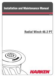
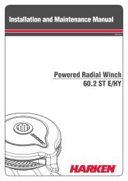
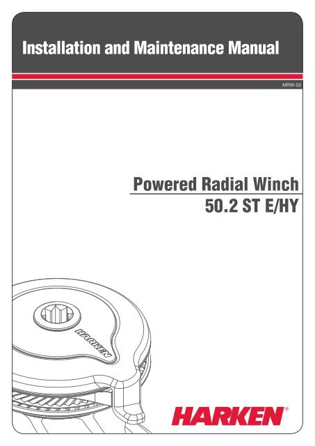
Installation and Maintenance Manual<br />
MRW-02<br />
<strong>Powered</strong> <strong>Radial</strong> <strong>Winch</strong><br />
<strong>50.2</strong> <strong>ST</strong> E/<strong>HY</strong>
Index<br />
Introduction<br />
Technical characteristics<br />
Performance data<br />
Weight<br />
Maximum working load<br />
Outline<br />
<strong>Winch</strong> <strong>50.2</strong> <strong>ST</strong> E/<strong>HY</strong><br />
Horizontal electric motor<br />
Vertical electric motor<br />
Hydraulic motor<br />
Installation<br />
Procedure 1<br />
Procedure 2<br />
<strong>Winch</strong> installation procedure<br />
Positioning the self-tailing arm<br />
Motor installation procedure<br />
Electric wiring diagrams<br />
Hydraulic connections diagram<br />
Maintenance<br />
Washing<br />
Maintenance table<br />
<strong>Winch</strong> disassembly procedure<br />
<strong>Winch</strong> exploded view with maintenance products<br />
<strong>Winch</strong> assembly<br />
<strong>Harken</strong> ® limited worldwide warranty<br />
Ordering spare parts<br />
Exploded view<br />
<strong>Winch</strong> <strong>50.2</strong> <strong>ST</strong> E/<strong>HY</strong><br />
Horizontal electric motor<br />
Vertical electric motor<br />
Hydraulic motor<br />
Parts list<br />
<strong>Radial</strong> <strong>Winch</strong> <strong>50.2</strong> <strong>ST</strong>A E/<strong>HY</strong><br />
<strong>Radial</strong> <strong>Winch</strong> <strong>50.2</strong> <strong>ST</strong>C E/<strong>HY</strong><br />
Horizontal electric motor<br />
Vertical electric motor<br />
Hydraulic motor<br />
3<br />
3<br />
3<br />
3<br />
4<br />
4<br />
4<br />
4<br />
5<br />
5<br />
6<br />
7<br />
8<br />
10<br />
11<br />
11<br />
12<br />
14<br />
16<br />
16<br />
16<br />
16<br />
20<br />
21<br />
22<br />
22<br />
23<br />
23<br />
27<br />
28<br />
29<br />
25<br />
25<br />
26<br />
27<br />
28<br />
29<br />
<strong>Radial</strong> <strong>Winch</strong> <strong>50.2</strong> <strong>ST</strong> E/<strong>HY</strong><br />
2<br />
Installation and Maintenance Manual
Introduction - Technical characteristics<br />
Introduction<br />
This manual gives technical information on winch installation and maintenance, including<br />
disassembling and reassembling.<br />
This information is DE<strong>ST</strong>INED EXCLUSIVELY for specialised personnel or expert users.<br />
Installation, disassembling and reassembling of the winch by personnel who are not experts may<br />
cause serious damage to users and those in the vicinity of the winch.<br />
<strong>Harken</strong> ® accepts no responsibility for defective installation or reassembly of its winches.<br />
In case of doubt the <strong>Harken</strong> ® Tech Service is at your disposal at techservice@harken.it<br />
This Manual is available only in English. If you do not fully understand the English language, do<br />
not carry out the operations described in this Manual.<br />
Technical characteristics<br />
Power ratio<br />
Gear ratio<br />
1st speed 10,90 : 1 2,40 : 1<br />
2nd speed 50,40 : 1 10,90 : 1<br />
The theoretical power ratio does not take friction into account.<br />
Performance data<br />
<strong>Winch</strong> <strong>50.2</strong> <strong>ST</strong> E (electric)<br />
horizontal motor<br />
vertical motor<br />
12 V (1500 W) 24 V (2000 W) 12 V (1500 W) 24 V (2000 W)<br />
1st<br />
speed<br />
2nd<br />
speed<br />
1st<br />
speed<br />
2nd<br />
speed<br />
1st<br />
speed<br />
2nd<br />
speed<br />
1st<br />
speed<br />
2nd<br />
speed<br />
line speed (m/min)** 32,7 7,2 39,4 8,7 37,4 8,2 45,1 9,9<br />
max load (Kg) 328 1494 341 15519 323 1472 335 1526<br />
**Line speed is measured with no load<br />
winch <strong>50.2</strong> <strong>ST</strong> E<br />
horizontal<br />
vertical<br />
current absorption at winch<br />
motor nominal power (W)<br />
MWL (A)<br />
12 V 24 V 12 V 24 V<br />
1500 2000<br />
275<br />
225<br />
155<br />
125<br />
<strong>Winch</strong> <strong>50.2</strong> <strong>ST</strong> <strong>HY</strong> (hydraulic)<br />
1st speed<br />
2nd speed<br />
line speed (m/min)* 55,9 12,3<br />
max load (Kg)* 344 1564<br />
*at 120 bar with a 20 L/min oil flow (5,28 Gal/min)<br />
<strong>Radial</strong> <strong>Winch</strong> <strong>50.2</strong> <strong>ST</strong> E/<strong>HY</strong><br />
3<br />
Installation and Maintenance Manual
Outline<br />
Weight<br />
<strong>ST</strong> A EH <strong>ST</strong> C EH <strong>ST</strong> A EV <strong>ST</strong> C EV <strong>ST</strong> A H <strong>ST</strong> C H<br />
weight (Kg) 16,8 20 17,5 20,7 13,5 16,7<br />
Versions:<br />
A = drum in anodised aluminium<br />
C = drum in chromed bronze<br />
EH = horizontal electric winch<br />
EV = vertical electric winch<br />
H = vertical hydraulic winch<br />
Maximum working load<br />
WARNING!<br />
The maximum working load (MWL) for the <strong>50.2</strong> <strong>ST</strong> E/<strong>HY</strong> <strong>Radial</strong> <strong>Winch</strong> is 1450 Kg (3197 lb).<br />
Subjecting the winch to loads above the maximum working load can cause the winch to fail or<br />
pull off the deck suddenly and unexpectedly during high loads causing severe injury or death.<br />
Outline<br />
<strong>Winch</strong> <strong>50.2</strong> <strong>ST</strong> E/<strong>HY</strong> Horizontal electric motor (12 V / 24 V)<br />
Ø194 mm<br />
Ø194 mm<br />
Ø111 mm<br />
96 mm<br />
Line entry height<br />
212,40 mm<br />
Ø111 mm<br />
155 mm<br />
69 mm<br />
96 mm<br />
Line entry height<br />
212,40 mm<br />
Ø 244 mm<br />
<strong>Radial</strong> <strong>Winch</strong> <strong>50.2</strong> <strong>ST</strong> E/<strong>HY</strong><br />
4<br />
Installation and Maintenance Manual
233 mm<br />
Vertical electric motor (12 V / 24 V)<br />
Hydraulic motor<br />
Ø194 mm<br />
Ø194 mm<br />
Ø111 mm<br />
96 mm<br />
Line entry height<br />
212,40 mm<br />
391 mm<br />
Ø111 mm<br />
96 mm<br />
Line entry height<br />
212,40 mm<br />
130 mm<br />
155 mm<br />
<strong>Radial</strong> <strong>Winch</strong> <strong>50.2</strong> <strong>ST</strong> E/<strong>HY</strong><br />
5<br />
Installation and Maintenance Manual
Installation<br />
Installation<br />
The winch must be installed on a flat area of the deck, reinforced if necessary to bear a load equal<br />
to at least twice the maximum working load of the winch.<br />
It is the installer's responsibility to carry out all structural tests needed to ensure that the deck can<br />
bear the load.<br />
<strong>Harken</strong> ® does not supply the screws needed to install the winch since these may vary depending<br />
on the deck on which it is to be installed.<br />
It is the installer's responsibility to choose the correct screws taking account of the loads they will<br />
have to bear.<br />
<strong>Harken</strong> ® assumes no responsibility for incorrect installation of its winches or for an incorrect choice<br />
of mounting screws.<br />
DANGER!<br />
Incorrect installation of the winch may cause severe injury or<br />
death. Consult the yard that built the boat in the case of doubt<br />
over the correct positioning of the winch.<br />
WARNING!<br />
Failure to use the correct number and type of mounting fasteners<br />
or failure to ensure the correct deck strength can result in the<br />
winch pulling off the deck suddenly and unexpectedly during<br />
high loads causing severe injury or death.<br />
WARNING!<br />
Verify the entry angle of the sheet. This must be 8° with tolerance<br />
of ±2°, to avoid sheet overrides and damaging the winch or<br />
making the winch inoperable leading to loss of control of the<br />
boat which can lead to severe injury or death.<br />
SHEET<br />
final drive gear<br />
8°<br />
WARNING!<br />
Mount the winch on the deck so that the final drive gear is<br />
positioned where the sheet enters the winch drum.<br />
Incorrect position of drive gear can weaken winch leading to failure<br />
which can cause an accident leading to severe injury or death.<br />
NOTICE<br />
You can find the icon<br />
position.<br />
on the skirt to identify the drive gear<br />
After correctly positioning the final drive gear with respect to the load, check that the motor,<br />
gearing, electrical wiring and/or hydraulic pipes can be housed below decks. To help find the<br />
optimal compromise, remember that, to make the installation of the motor easier, it can be<br />
coupled to the winch in any one of four different positions that differ by 60° from each other.<br />
Once you have decided the correct mounting position for the winch on the deck and checked the<br />
space available below deck, proceed with the installation.<br />
<strong>Radial</strong> <strong>Winch</strong> <strong>50.2</strong> <strong>ST</strong> E/<strong>HY</strong><br />
6<br />
Installation and Maintenance Manual
The winch can be installed following one of the two procedures below (Procedure1 or Procedure 2):<br />
Procedure 1<br />
To install the winch you must remove the drum and use Socket Head (SH) bolts.<br />
Tools needed<br />
One medium flat-bladed screwdriver<br />
To identify the various parts, refer to the exploded view at the end of this Manual.<br />
Torque to apply when assembling<br />
1. Pull out the disconnect rod n°32<br />
2. Unscrew the central screw ( 2Nm/18 in-lb)<br />
3. Slide off the assy socket n°31 and the cover n°30.<br />
Pay attention to the o-ring in the socket.<br />
4. Unscrew the three screws n°29<br />
( 4Nm/35 in-lb)<br />
<strong>Radial</strong> <strong>Winch</strong> <strong>50.2</strong> <strong>ST</strong> E/<strong>HY</strong><br />
7<br />
Installation and Maintenance Manual
5. Remove the stripper arm n°28 by<br />
rotating and lifting it.<br />
6. Lift off the drum n°24<br />
Install the winch on the deck in the position you have chosen, keeping in mind the limits described<br />
on page 6 and using socket head (SH) bolts.<br />
(See paragraph on installation)<br />
Procedure 2<br />
To install, you must remove the winch skirt and use hexagonal headed bolts.<br />
Tools needed<br />
One medium flat-bladed screwdriver<br />
To identify the various parts, refer to the exploded view at the end of this Manual.<br />
1. Remove the skirt n°2 with the help of<br />
the screwdriver placed as shown by<br />
the symbol<br />
2. Take off the base n°2<br />
<strong>Radial</strong> <strong>Winch</strong> <strong>50.2</strong> <strong>ST</strong> E/<strong>HY</strong><br />
8<br />
Installation and Maintenance Manual
3. Position the 5 M8 hexagonal headed<br />
bolts in their holes<br />
4.<br />
5. Reposition the skirt n°2 in its housing<br />
6. Press down the skirt to position it correctly<br />
NOTICE<br />
Make sure the skirt is correctly clipped on to the base of the winch.<br />
Install the winch on the deck in the position you have chosen, keeping in mind the limits described<br />
on page 6 and using hexagonal headed bolts.<br />
(See paragraph on winch installation)<br />
<strong>Radial</strong> <strong>Winch</strong> <strong>50.2</strong> <strong>ST</strong> E/<strong>HY</strong><br />
9<br />
Installation and Maintenance Manual
<strong>Winch</strong> installation procedure<br />
Carry out Procedure 1 or Procedure 2, then install the winch on the deck in the chosen position.<br />
NOTICE<br />
Before drilling the deck, check the space available below deck for the flange and the motor<br />
A. Position the base of the winch on the deck and mark the position of the holes or use the drilling<br />
cut-out template at the point where you have decided to place the winch.<br />
Below is a reduced scale diagram.<br />
The drilling cut out template is available on the <strong>Harken</strong> ® website, www.harken.com<br />
final<br />
drive gear<br />
position<br />
B. Remove the winch and drill the five 8.2 mm diameter holes.<br />
C. Bolt the base of the winch to the deck using five M8 Socket Head (SH) bolts for Procedure 1 or five<br />
hexagonal headed M8 bolts for Procedure 2 (neither is supplied by <strong>Harken</strong> ® ), correctly chosen for<br />
the thickness and type of the boat deck. Consult the yard that built the boat in case of doubt.<br />
WARNING!<br />
To install the winch on the deck, use only bolts in A4 stainless steel (DIN 267 part11).<br />
Bolts made of other materials may not have sufficient strength or may corrode which can<br />
result in winch pulling off deck suddenly and unexpectedly during high loads causing<br />
severe injury or death.<br />
NOTICE<br />
To mount winches on the deck, do not use countersunk bolts.<br />
D. Fill the mounting holes with a suitable marine sealant.<br />
E. Remove the excess adhesive/sealant from the holes and base drainage channels<br />
<strong>Radial</strong> <strong>Winch</strong> <strong>50.2</strong> <strong>ST</strong> E/<strong>HY</strong><br />
10<br />
Installation and Maintenance Manual
Motor installation procedure<br />
F. Reassemble the winch following the steps in Procedure 1 or Procedure 2 in the reverse order,<br />
and apply the products indicated in the section on maintenance.<br />
NOTICE<br />
Before closing the winch, make sure the holes and drainage channels in the base of the winch are not obstructed.<br />
Positioning the self-tailing arm<br />
Position the self-tailing arm so that the line leaving the winch is led into the cockpit.<br />
Motor installation procedure<br />
Once you have installed the winch on the deck, proceed with motor installation. The motor can be coupled<br />
to the winch in different positions. Check the space available below deck and choose the suitable position.<br />
Tools needed<br />
A number five hex key<br />
A number six hex key (only for vertical electric motor)<br />
A number ten hex key (only for hydraulic motor)<br />
Two number thirteen wrenches<br />
1. Position the flange (see Page 12)<br />
2. Tighten the six screws ( 8 Nm/ 71 in-lb)<br />
3. Position the reduction gear and motor<br />
4. Tighten the two screws ( 8 Nm/ 71in-lb).<br />
Be sure to align the flange.<br />
<strong>Radial</strong> <strong>Winch</strong> <strong>50.2</strong> <strong>ST</strong> E/<strong>HY</strong><br />
11<br />
Installation and Maintenance Manual
NOTICE<br />
Before positioning the flange, check to make sure<br />
that seal is seated correctly.<br />
After winch is assembled and before sailing, test the powered winch functioning: insert the lock-in<br />
winch handle in the handle socket and check that the disconnect rod must disconnect gearbox.<br />
Electric wiring diagrams<br />
To guarantee greater efficiency in terms of safety and long life, for certain winch models it is<br />
obligatory to install the WLC 200R Load Controller.<br />
WARNING! Consult the table below to check for which winch models it is obligatory to install<br />
the WLC200R and for which it is recommended.<br />
WINCH<br />
RADIAL<br />
Horizontal motor<br />
Vertical motor<br />
12 V 24 V 12 V 24 V<br />
<strong>50.2</strong> recommended obligatory obligatory obligatory<br />
For more information, refer to the WLC200R Manual.<br />
Refer to the following diagrams for the electric wiring:<br />
Horizontal 12 V / 24 V motor installed without WLC200R<br />
WINCH<br />
&<br />
MOTOR<br />
1D1 A2 2D2<br />
ELECTRICAL<br />
CONTROL BOX<br />
M1<br />
A1 C A2<br />
M2<br />
FUSE<br />
SWITCHES<br />
CIRCUIT BREAKER<br />
BATTERY<br />
<strong>Radial</strong> <strong>Winch</strong> <strong>50.2</strong> <strong>ST</strong> E/<strong>HY</strong><br />
12<br />
Installation and Maintenance Manual
WLC200R<br />
WLC200R<br />
Horizontal 12 V / 24 V motor in right-hand configuration installed with WLC200R<br />
TOP VIEW<br />
WINCH<br />
&<br />
MOTOR<br />
1D1 A2 2D2<br />
M1<br />
M2<br />
A1 C A2 ELECTRICAL<br />
CONTROL BOX<br />
A1 C A2<br />
batt-<br />
Motor-<br />
WLC200R<br />
SWITCHES<br />
5 amp fuse<br />
CIRCUIT<br />
BREAKER<br />
+ -<br />
BATTERY<br />
Horizontal 12 V / 24 V motor in left-hand configuration installed with WLC200R<br />
TOP VIEW<br />
WINCH<br />
&<br />
MOTOR<br />
1D1 A2 2D2<br />
M1<br />
M2<br />
A1 C A2 ELECTRICAL<br />
CONTROL BOX<br />
A1 C A2<br />
batt-<br />
Motor-<br />
WLC200R<br />
SWITCHES<br />
5 amp fuse<br />
CIRCUIT<br />
BREAKER<br />
+ -<br />
BATTERY<br />
<strong>Radial</strong> <strong>Winch</strong> <strong>50.2</strong> <strong>ST</strong> E/<strong>HY</strong><br />
13<br />
Installation and Maintenance Manual
Vertical 12 V / 24 V motor with WLC200R<br />
1D1 A2 2D2<br />
WINCH<br />
&<br />
MOTOR<br />
M1<br />
M2<br />
A1 C A2 ELECTRICAL<br />
CONTROL BOX<br />
A1 C A2<br />
batt-<br />
Motor-<br />
WLC200R<br />
WLC200R<br />
SWITCHES<br />
5 amp fuse<br />
CIRCUIT<br />
BREAKER<br />
+ -<br />
BATTERY<br />
Fasten electric control box containing solenoids to bulkhead or wall. Install remote circuit breaker<br />
between power supply and electric control box. Locate push-buttons on deck in a convenient spot<br />
for easy winch operation.<br />
Refer to the following chart for wire size:<br />
<strong>Winch</strong><br />
size<br />
Current<br />
voltage<br />
Under 16.4 ft<br />
AWG<br />
Total distance between winch and battery<br />
Under 5 m<br />
mm 2<br />
16.4 - 32.8 ft<br />
AWG<br />
5 m - 10 m<br />
mm 2<br />
32.8 - 49.2 ft<br />
AWG<br />
10 m - 15 m<br />
mm 2<br />
49.2 - 65.6 ft<br />
AGW<br />
15m - 20 m<br />
mm 2<br />
<strong>50.2</strong> 12 V 2 32 0 50 00 70 000 95<br />
<strong>50.2</strong> 24 V 5 16 3 25 2 35 0 50<br />
<strong>Radial</strong> <strong>Winch</strong> <strong>50.2</strong> <strong>ST</strong> E/<strong>HY</strong><br />
14<br />
Installation and Maintenance Manual
NOTICE<br />
To connect motor, attach cable terminals to clamps between<br />
nut and lock nut. Hold nut in contact with motor using a<br />
spanner and tighten other nut with second spanner. Take<br />
special care not to turn the central spindles. Be careful not<br />
to turn central spindles. These instructions apply when<br />
assembling and disassembling. We recommend using a<br />
torque wrench so as to obtain a torque equal to and no<br />
greater than 10 Nm (88 in-lb).<br />
NOTICE<br />
Note that correct electrical contact sequence is:<br />
Nut – Cable Terminal – Self-Locking Washer – Lock Nut<br />
Hydraulic connections diagram<br />
The hydraulic motor must to be connected to a hydraulic system using two high-pressure tubes<br />
which serve for input or output according to the direction in which the motor will be run. The motor<br />
also needs a third connection with a low pressure tube for drainage, so that excess oil can return to<br />
the main tank to avoid shortening the life of the motor. This motor uses an open centre valve.<br />
Refer to the following chart for the hydraulic system:<br />
WINCH<br />
&<br />
MOTOR<br />
For the hydraulic motor:<br />
Input/output pipe thread: G 1/2 – depth 15 mm<br />
Drainage pipe thread: G 1/4 – depth 12 mm<br />
SWITCHES<br />
CONTROL BOX<br />
<strong>HY</strong>DRAULIC POWER UNIT<br />
(HPU)<br />
BATTERY<br />
<strong>Radial</strong> <strong>Winch</strong> <strong>50.2</strong> <strong>ST</strong> E/<strong>HY</strong><br />
15<br />
Installation and Maintenance Manual
Maintenance<br />
Maintenance<br />
Washing<br />
<strong>Winch</strong>es must be washed frequently with fresh water, and in any case after each use.<br />
Do not allow teak cleaning products or other cleaners containing caustic solutions to come into<br />
contact with winches and especially anodised, chrome plated or plastic parts.<br />
Do not use solvents, polishes or abrasive pastes on the logos or stickers on the winches.<br />
Make sure that the holes and drainage channels in the base of the winch are not obstructed so<br />
that water does not collect.<br />
Maintenance table<br />
<strong>Winch</strong>es must be visually inspected at the beginning and end of every season of sailing or racing.<br />
In addition they must be completely overhauled, cleaned and lubricated at least every 12 months.<br />
After an inspection, replace worn or damaged components. Do not replace or modify any part of<br />
the winch with a part that is not original.<br />
WARNING!<br />
Periodic maintenance must be carried out regularly. Lack of adequate maintenance<br />
shortens the life of the winch, can cause serious injury and also invalidate the winch<br />
warranty. Installation and maintenance of winches must be carried out exclusively by<br />
specialized personnel.<br />
In the case of doubt contact <strong>Harken</strong> ® Tech Service at techservice@harken.it<br />
WARNING!<br />
Make sure that the power is switched off before installing or carrying out maintenance on<br />
the winch.<br />
<strong>Winch</strong> disassembly procedure<br />
Tools needed<br />
One medium flat-bladed screwdriver<br />
A number six hex key<br />
Brush<br />
Rags<br />
<strong>Radial</strong> <strong>Winch</strong> <strong>50.2</strong> <strong>ST</strong> E/<strong>HY</strong><br />
16<br />
Installation and Maintenance Manual
To identify the various parts refer to the exploded view at the end of this Manual.<br />
Torque to be applied in assembly phase<br />
Carry out Procedure 1 as shown in the paragraph on winch installation and then do the following:<br />
7. Completely unscrew the three screws n° 29<br />
and remove the stripper arm support n°23<br />
8. Slide out the central shaft n°21<br />
9.Unscrew the 5 hex screws n°18<br />
( 20Nm/177 in-lb)<br />
10. Remove the assy housing n°17<br />
Important: washer n°14 may remain inside<br />
the drum support!<br />
11. Remove the gear n°16<br />
12. Remove the washer n°14<br />
<strong>Radial</strong> <strong>Winch</strong> <strong>50.2</strong> <strong>ST</strong> E/<strong>HY</strong><br />
17<br />
Installation and Maintenance Manual
13. Remove the gear n°10<br />
14. Remove the pawls carrier n°7<br />
15. Remove the gear n°3 16. Remove the pinion n°11. To facilitate the operation<br />
press the spring against the pawl with a blade<br />
17. Slide off gear n°6<br />
<strong>Radial</strong> <strong>Winch</strong> <strong>50.2</strong> <strong>ST</strong> E/<strong>HY</strong><br />
18<br />
Installation and Maintenance Manual
If it is necessary to replace any jaws of the winch, proceed as follows:<br />
I. Unscrew the 4 screws n°27<br />
( 4Nm/35 in-lb)<br />
II. Remove the jaws n°26<br />
Once the winch is completely disassembled, clean the parts: use a basin of diesel oil to soak<br />
metal components and rinse plastic parts in fresh water. Once you have done this, dry the parts<br />
with cloths that do not leave residue.<br />
Inspect gears, bearings, pins and pawls for any signs of wear or corrosion.<br />
Carefully check the teeth of gears and ring gears to make sure there are no traces of wear.<br />
Check the roller bearings and check there are no breaks in the bearing cages.<br />
Replace worn or damaged components.<br />
Carry out maintenance on components using the products listed below.<br />
For more information on which products to use where, refer to the exploded diagram below.<br />
Use a brush to lightly lubricate all gears, gear pins, teeth and all moving parts with grease.<br />
Lightly lubricate the pawls and springs with oil. Do not use grease on the pawls!<br />
<strong>Radial</strong> <strong>Winch</strong> <strong>50.2</strong> <strong>ST</strong> E/<strong>HY</strong><br />
19<br />
Installation and Maintenance Manual
<strong>Winch</strong> exploded view with maintenance products<br />
G 1 G 2<br />
G<br />
A<br />
G<br />
O<br />
Anti-seize<br />
<strong>Harken</strong> ® Grease<br />
<strong>Harken</strong> ® Pawl Oil<br />
A<br />
A<br />
G<br />
A<br />
G<br />
G<br />
O<br />
G<br />
G<br />
G<br />
O<br />
G<br />
G 3<br />
G<br />
A<br />
1Apply <strong>Harken</strong> ®<br />
grease on assy socket screw<br />
2Apply <strong>Harken</strong> ®<br />
grease on drum gear<br />
3Apply <strong>Harken</strong> ®<br />
grease on the middle step of assy housing<br />
<strong>Radial</strong> <strong>Winch</strong> <strong>50.2</strong> <strong>ST</strong> E/<strong>HY</strong><br />
20<br />
Installation and Maintenance Manual
<strong>Winch</strong> assembly<br />
Make sure that the holes and drainage channels in the base of the winch are not obstructed<br />
Assemble the winch in the reverse order of the sequence in the section on disassembly.<br />
To tighten bolts, use the torque indicated in the disassembly procedure.<br />
When positioning the stripper arm,<br />
align the peeler with it.<br />
OIL<br />
If the jaws have been disassembled,<br />
insert peeler between the two jaws,<br />
taking care that the letters TOP on the<br />
peeler are facing upwards.<br />
To assemble the pawls:<br />
correctly position the spring in its housing as<br />
shown at left. Hold the spring closed and slide<br />
the pawl into its housing. Once in position,<br />
check that the pawls can be easily opened and<br />
closed with a finger.<br />
NOTICE<br />
Before screw the central screw, check the<br />
correct position of the o-ring in the assy socket.<br />
In case of doubt concerning the assembly procedure contact <strong>Harken</strong> ® Tech Service: techservice@harken.it<br />
<strong>Radial</strong> <strong>Winch</strong> <strong>50.2</strong> <strong>ST</strong> E/<strong>HY</strong><br />
21<br />
Installation and Maintenance Manual
<strong>Harken</strong> ® limited worldwide warranty - Ordering spare parts<br />
<strong>Harken</strong> ® limited worldwide warranty<br />
Refer to the <strong>Harken</strong> ® Limited Worldwide Warranty in the <strong>Harken</strong> ® Catalogue and on the website<br />
www.harken.com<br />
Ordering spare parts<br />
Spare parts can be requested from <strong>Harken</strong> ® as<br />
described in the <strong>Harken</strong> ® Limited Worldwide<br />
Warranty, indicating the part number in the<br />
Parts List and including the serial number of<br />
the winch for which the parts are required.<br />
W XXXXX<br />
XXXXXXXXX<br />
The serial number of the winch is printed on<br />
a plate on the drum support of the winch.<br />
Manufacturer<br />
<strong>Harken</strong> ® Italy S.p.A.<br />
Via Marco Biagi, 14<br />
22070 Limido Comasco (CO) Italy<br />
Tel: (+39) 031.3523511<br />
Fax: (+39) 031.3520031<br />
Email: info@harken.it<br />
Web: www.harken.com<br />
Tech Service<br />
Email: techservice@harken.it<br />
Customer Service<br />
Tel: (+39) 031.3523511<br />
Email: info@harken.it<br />
Headquarters<br />
<strong>Harken</strong> ® , Inc.<br />
1251 East Wisconsin Avenue<br />
Pewaukee, Wisconsin 53072-3755 USA<br />
Tel: (262) 691.3320<br />
Fax: (262) 691.3008<br />
Email: harken@harken.com<br />
Web: www.harken.com<br />
Tech Service<br />
Email: technicalservice@harken.com<br />
Customer Service<br />
Tel: (262) 691-3320<br />
Email: customerservice@harken.com<br />
<strong>Radial</strong> <strong>Winch</strong> <strong>50.2</strong> <strong>ST</strong> E/<strong>HY</strong><br />
22<br />
Installation and Maintenance Manual
Exploded view 1/2<br />
<strong>Radial</strong> <strong>Winch</strong> <strong>50.2</strong> <strong>ST</strong>A E/<strong>HY</strong><br />
31<br />
22<br />
24<br />
25<br />
19<br />
20<br />
19<br />
17<br />
18<br />
30<br />
29<br />
28<br />
23<br />
27<br />
26<br />
<strong>Radial</strong> <strong>Winch</strong> <strong>50.2</strong> <strong>ST</strong> E/<strong>HY</strong><br />
23<br />
Installation and Maintenance Manual
Exploded view 2/2<br />
<strong>Radial</strong> <strong>Winch</strong> <strong>50.2</strong> <strong>ST</strong>A E/<strong>HY</strong><br />
32<br />
21<br />
14<br />
10<br />
8<br />
9<br />
7<br />
3<br />
15<br />
16<br />
4<br />
12<br />
13<br />
12<br />
11<br />
9<br />
8<br />
6<br />
5<br />
1<br />
2<br />
<strong>Radial</strong> <strong>Winch</strong> <strong>50.2</strong> <strong>ST</strong> E/<strong>HY</strong><br />
24<br />
Installation and Maintenance Manual
Parts list<br />
<strong>Radial</strong> <strong>Winch</strong> <strong>50.2</strong> <strong>ST</strong>A E/<strong>HY</strong><br />
A= drum in anodised aluminium<br />
Pos. Q.ty Code Description<br />
1 1 A 941898 00 Assy Base <strong>Winch</strong> 50 EL/<strong>HY</strong><br />
<strong>Winch</strong> Serial Number Sticker<br />
2 1 A 941349 00 Assy Skirt <strong>Winch</strong> 50**<br />
3 1 S 41302 00 04 Gear Z12<br />
4 1 S 41605 00 04 Pin<br />
5 1 S278170002 Washer 12.5x48x1.5*<br />
6 1 S 41280 00 41 Gear Z30<br />
7 1 S 41426 00 04 Pawls Carrier Ø8xN2<br />
8 6 S 00008 00 03 Pawl Ø8*<br />
9 6 S 00038 00 01 Pawl Spring Ø8*<br />
10 1 S 41559 00 41 Gear Z20<br />
11 1 S 41561 00 04 Pinion Z11<br />
12 2 A72821800 Roller Bearing 14/20/18*<br />
13 2 S281340080 Spacer roller bearings*<br />
14 1 S 41312 00 02 Washer Ø22.5xØ45x1*<br />
15 1 S 41307 00 04 Pin<br />
16 1 A 941560 00 Assy Gear Z11<br />
17 1 A 941348 00 Assy Housing <strong>Winch</strong> 50<br />
18 5 M0643203 Screw M8x20 UNI5931*<br />
19 2 A 741351 00 Bearing Ø85xØ97x26*<br />
20 1 S 41352 00 80 Spacer*<br />
21 1 A 941508 00 Assy Central Shaft W50<br />
22 1 S418760063 <strong>Winch</strong> Serial Number Sticker<br />
23 1 S4129400A0 Stripper arm support<br />
24 1 S41340 00 53 Drum A W50<br />
25 1 S 28169 00 97 Red line<br />
26 1 A 941343 00 Assy Jaws <strong>Winch</strong> 50<br />
Lower Jaw W50<br />
Upper Jaw W50<br />
Peeler W46-50<br />
Spring<br />
27 4 M0601803 Screw UNI EN ISO 1207:1996 - M6x35 - A4*<br />
28 1 S 41344 00 19 Stripper Arm W50<br />
29 3 M6007103 Screw M6x50 UNI6107*<br />
30 1 S 41345 00 A5 Cover 2 speed W50<br />
31 1 A 941493 00<br />
Assy - Socket W35-80 EL/<strong>HY</strong><br />
Nut screw for disconnect rod<br />
Washer Ø25x15x4<br />
Socket Handle W20/80<br />
O ring 2025 series<br />
32 1 S 41507 00 02 Disconnect Rod W50<br />
*Service kit available; see winch kit section on the website www.harken.com<br />
**<strong>Winch</strong> product sticker<br />
<strong>Radial</strong> <strong>Winch</strong> <strong>50.2</strong> <strong>ST</strong> E/<strong>HY</strong><br />
25<br />
Installation and Maintenance Manual
Parts list<br />
<strong>Radial</strong> <strong>Winch</strong> <strong>50.2</strong> <strong>ST</strong>C E/<strong>HY</strong><br />
C=drum in chromed bronze<br />
Pos. Q.ty Code Description<br />
1 1 A 941898 00 Assy Base <strong>Winch</strong> 50 EL/<strong>HY</strong><br />
<strong>Winch</strong> Serial Number Sticker<br />
2 1 A 941349 00 Assy Skirt <strong>Winch</strong> 50**<br />
3 1 S 41302 00 04 Gear Z12<br />
4 1 S 41605 00 04 Pin<br />
5 1 S278170002 Washer 12.5x48x1.5*<br />
6 1 S 41280 00 41 Gear Z30<br />
7 1 S 41426 00 04 Pawls Carrier Ø8xN2<br />
8 6 S 00008 00 03 Pawl Ø8*<br />
9 6 S 00038 00 01 Pawl Spring Ø8*<br />
10 1 S 41559 00 41 Gear Z20<br />
11 1 S 41561 00 04 Pinion Z11<br />
12 2 A72821800 Roller Bearing 14/20/18*<br />
13 2 S281340080 Spacer roller bearings*<br />
14 1 S 41312 00 02 Washer Ø22.5xØ45x1*<br />
15 1 S 41307 00 04 Pin<br />
16 1 A 941560 00 Assy Gear Z11<br />
17 1 A 941348 00 Assy Housing <strong>Winch</strong> 50<br />
18 5 M0643203 Screw M8x20 UNI5931*<br />
19 2 A 741351 00 Bearing Ø85xØ97x26*<br />
20 1 S 41352 00 80 Spacer*<br />
21 1 A 941508 00 Assy Central Shaft W50<br />
22 1 S418760063 <strong>Winch</strong> Serial Number Sticker<br />
23 1 S4129400A0 Stripper arm support<br />
24 1 S413410043<br />
Drum C W50<br />
25 1 S 28169 00 97 Red line<br />
26 1 A 941343 00 Assy Jaws <strong>Winch</strong> 50<br />
Lower Jaw W50<br />
Upper Jaw W50<br />
Peeler W46-50<br />
Spring<br />
27 4 M0601803 Screw UNI EN ISO 1207:1996 - M6x35 - A4*<br />
28 1 S 41344 00 19 Stripper Arm W50<br />
29 3 M6007103 Screw M6x50 UNI6107*<br />
30 1 S 41345 00 A5 Cover 2 speed W50<br />
31 1 A 941493 00<br />
Assy - Socket W35-80 EL/<strong>HY</strong><br />
Nut screw for disconnect rod<br />
Washer Ø25x15x4<br />
Socket Handle W20/80<br />
O ring 2025 series<br />
32 1 S 41507 00 02 Disconnect Rod W50<br />
*Service kit available; see winch kit section on the website www.harken.com<br />
**<strong>Winch</strong> product sticker<br />
<strong>Radial</strong> <strong>Winch</strong> <strong>50.2</strong> <strong>ST</strong> E/<strong>HY</strong><br />
26<br />
Installation and Maintenance Manual
Horizontal electric motor<br />
3<br />
4<br />
2<br />
1<br />
5<br />
TOP VIEW<br />
* Motor installed in<br />
right-hand configuration.<br />
Pos. Q.ty Code Description<br />
1 1<br />
A 931279 00<br />
A 941949 00<br />
KIT Gear Reduction VF49*<br />
KIT LM Gear Reduction VF49**<br />
2 1 A 941492 00<br />
KIT Assy Electric Motor Flange<br />
3 1 A 949665 00<br />
KIT EL HO Motor Flange<br />
4 1 A 949524 00<br />
KIT EL HO Motor Clutch<br />
5 1<br />
A 960107 00<br />
A 960106 00<br />
KIT EL Motor 12V 1,5kW<br />
KIT EL Motor 24V 2kW<br />
** Motor installed in<br />
left-hand configuration.<br />
<strong>Radial</strong> <strong>Winch</strong> <strong>50.2</strong> <strong>ST</strong> E/<strong>HY</strong><br />
27<br />
Installation and Maintenance Manual
Vertical electric motor<br />
3<br />
2<br />
4<br />
1<br />
Pos. Q.ty Code<br />
1 1<br />
A 960105 00<br />
A 960104 00<br />
2 1 A 932937 00<br />
3 1 A 941505 00<br />
4 1 A 941937 00<br />
Description<br />
KIT EL Motor 12V 1,5kW VT<br />
KIT EL Motor 24V 2kW VT<br />
KIT VT Gearbox (AS16F20.96)<br />
KIT EL VT Motor Flange<br />
KIT EL VT Motor Clutch<br />
<strong>Radial</strong> <strong>Winch</strong> <strong>50.2</strong> <strong>ST</strong> E/<strong>HY</strong><br />
28<br />
Installation and Maintenance Manual
Hydraulic motor<br />
4<br />
2<br />
3<br />
1<br />
Pos. Q.ty Code Description<br />
1 1 G45942000Y Hydraulic motor "OMR50 151-0420 alb.scan. 1"<br />
2 1 S 41500 00 82<br />
Hydraulic Motor Spacer<br />
3 1 A 941932 00<br />
KIT Clutch <strong>HY</strong> Motor (OMR50)<br />
4 1 A 941491 00<br />
KIT <strong>HY</strong> Motor Flange (OMR50)<br />
<strong>Radial</strong> <strong>Winch</strong> <strong>50.2</strong> <strong>ST</strong> E/<strong>HY</strong><br />
29<br />
Installation and Maintenance Manual