Hayward Pro™ Series High-Rate Sand Filters ... - Pool Center
Hayward Pro™ Series High-Rate Sand Filters ... - Pool Center
Hayward Pro™ Series High-Rate Sand Filters ... - Pool Center

Create successful ePaper yourself
Turn your PDF publications into a flip-book with our unique Google optimized e-Paper software.
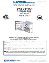
IS311SX<br />
Rev B<br />
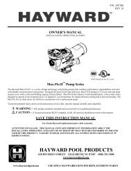
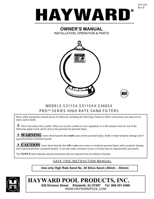
OWNER’S MANUAL<br />
INSTALLATION, OPERATION & PARTS<br />
MODELS S311SX.S311SXV,S360SX<br />
PRO SERIES HIGH RATE SAND FILTERS<br />
Basic safety precautions should always be followed, including the following: Failure to follow instructions can cause severe<br />
injury and/or death.<br />
This is the safety-alert symbol. When you see this symbol on your equipment or in this manual, look for one of the<br />
following signal words and be alert to the potential for personal injury.<br />
WARNING warns about hazards that could cause serious personal injury, death or major property damage and if<br />
ignored presents a potential hazard.<br />
CAUTION warns about hazards that will or can cause minor or moderate personal injury and/or property damage<br />
and if ignored presents a potential hazard. It can also make consumers aware of actions that are unpredictable and unsafe.<br />
The NOTICE label indicates special instructions that are important but not related to hazards.<br />
SAVE THIS INSTRUCTION MANUAL<br />
Use only <strong>High</strong> <strong>Rate</strong> <strong>Sand</strong> No. 20 Silica <strong>Sand</strong> (.45mm - .55mm)<br />
HAYWARD POOL PRODUCTS, INC.<br />
620 Division Street Elizabeth, NJ 07207 Tel: 908-351-5400<br />
WWW.HAYWARDPOOL.COM
Page 2 of 8 MODEL S311SX,S311SXV,S360SX IS311SX Rev B<br />
- WARNING - Read and follow all instructions in this owner’s manual and on the equipment. Failure to follow<br />
instructions can cause severe injury and/or death.<br />
WARNING – Suction Entrapment Hazard.<br />
Suction in suction outlets and/or suction outlet covers which are, damaged, broken, cracked, missing, or unsecured can cause severe injury<br />
and/or death due to the following entrapment hazards:<br />
Hair Entrapment- Hair can become entangled in suction outlet cover.<br />
Limb Entrapment- A limb inserted into an opening of a suction outlet sump or suction outlet cover that is damaged, broken, cracked,<br />
missing, or not securely attached can result in a mechanical bind or swelling of the limb.<br />
Body Suction Entrapment- A negative pressure applied to a large portion of the body or limbs can result in an entrapment.<br />
Evisceration/ Disembowelment - A negative pressure applied directly to the intestines through an unprotected suction outlet sump or suction<br />
outlet cover which is, damaged, broken, cracked, missing, or unsecured can result in evisceration/ disembowelment.<br />
Mechanical Entrapment- There is potential for jewelry, swimsuit, hair decorations, finger, toe or knuckle to be caught in an opening of a<br />
suction outlet cover resulting in mechanical entrapment.<br />
WARNING - To Reduce the risk of Entrapment Hazards:<br />
o When outlets are small enough to be blocked by a person, a minimum of two functioning suction outlets per pump must be installed.<br />
Suction outlets in the same plane (i.e. floor or wall), must be installed a minimum of three feet (3’) [1 meter] apart, as measured from<br />
near point to near point.<br />
o Dual suction fittings shall be placed in such locations and distances to avoid “dual blockage” by a user.<br />
o Dual suction fittings shall not be located on seating areas or on the backrest for such seating areas.<br />
o The maximum system flow rate shall not exceed the flow rating of as listed on Table 2.<br />
o Never use <strong>Pool</strong> or Spa if any suction outlet component is damaged, broken, cracked, missing, or not securely attached.<br />
o Replace damaged, broken, cracked, missing, or not securely attached suction outlet components immediately.<br />
o In addition two or more suction outlets per pump installed in accordance with latest NSPI, IAF Standards and CPSC guidelines, follow all National,<br />
State, and Local codes applicable.<br />
o Installation of a vacuum release or vent system, which relieves entrapping suction, is recommended.<br />
WARNING – Failure to remove pressure test plugs and/or plugs used in winterization of the pool/spa from the suction<br />
outlets can result in an increase potential for suction entrapment as described above.<br />
WARNING – Failure to keep suction outlet components clear of debris, such as leaves, dirt, hair, paper and other material<br />
can result in an increase potential for suction entrapment as described above.<br />
WARNING – Suction outlet components have a finite life, the cover/grate should be inspected frequently and replaced at<br />
least every ten years or if found to be damaged, broken, cracked, missing, or not securely attached.<br />
CAUTION – Components such as the filtration system, pumps and heater must be positioned so as to prevent their being<br />
used as means of access to the pool by young children.<br />
WARNING – Never operate or test the circulation system at more than 40 PSI.<br />
CAUTION – All electrical wiring MUST be performed by a qualified professional, and MUST conform to local codes and<br />
regulations.<br />
WARNING – Never change the filter control valve position while the pump is running.<br />
WARNING – Hazardous Pressure. <strong>Pool</strong> and spa water circulation systems operate under hazardous pressure during start<br />
up, normal operation, and after pump shut off. Stand clear of circulation system equipment during pump start up. Failure to follow<br />
safety and operation instructions could result in violent separation of the pump housing and cover, and/or filter housing and clamp due to<br />
pressure in the system, which could cause property damage, severe personal injury, or death. Before servicing pool and spa water<br />
circulation system, all system and pump controls must be in off position and filter manual air relief valve must be in open position. Before starting<br />
system pump, all system valves must be set in a position to allow system water to return back to the pool. Do not change filter control valve position<br />
while system pump is running. Before starting system pump, fully open filter manual air relief valve. Do not close filter manual air relief valve until a<br />
steady stream of water (not air or air and water) is discharged.<br />
WARNING – Separation Hazard. Failure to follow safety and operation instructions could result in violent separation of pump<br />
and/or filter components. Strainer cover must be properly secured to pump housing with strainer cover lock ring. Before servicing pool and<br />
spa circulation system, the filter’s manual air relief valve must be in open position. Do not operate pool and spa circulation system if a<br />
system component is not assembled properly, damaged, or missing. Do not operate pool and spa circulation system unless filter manual air<br />
relief valve body is in locked position in filter upper body.<br />
WWW.HAYWARDPOOL.COM<br />
USE ONLY HAYWARD GENUINE REPLACEMENT PARTS
Page 3 of 8 MODEL S311SX,S311SXV,S360SX IS311SX Rev B<br />
WARNING – Electrical Ground motor before connecting to electrical power supply. Failure to ground pump motor can cause<br />
serious or fatal electrical shock hazard.<br />
WARNING – Do NOT ground to a gas supply line.<br />
WARNING – To avoid dangerous or fatal electrical shock, turn OFF power to motor before working on electrical connections.<br />
WARNING – Failure to bond pump to pool structure will increase risk for electrocution and could result in injury or death. To reduce the risk<br />
of electric shock, see installation instructions and consult a professional electrician on how to bond pump. Also, contact a licensed electrician for<br />
information on local electrical codes for bonding requirements.<br />
Your <strong>Hayward</strong> Pro <strong>Series</strong> high-rate sand filter is a high<br />
performance, totally corrosion-proof filter that blends superior<br />
flow characteristics and features with ease of operation. It<br />
represents the very latest in high-rate sand filter technology.<br />
It is virtually foolproof in design and operation and when<br />
installed, operated and maintained according to instructions,<br />
your filter will produce clear, sparkling water with only the<br />
least attention and care.<br />
HOW IT WORKS<br />
Your filter uses special filter sand to remove dirt particles<br />
from the water. Filter sand is loaded into the filter tank and<br />
functions as the permanent dirt removing media. The pool<br />
water, which contains suspended dirt particles, is pumped<br />
through your piping system and is automatically directed by<br />
the patented filter control valve to the top of the filter tank. As<br />
the pool water is pumped through the filter sand, dirt particles<br />
are trapped by the sand bed, and filtered out. The cleaned<br />
pool water is returned from the bottom of the filter tank,<br />
through the control valve and back to the pool through the<br />
piping system. This entire sequence is continuous and<br />
automatic and provides for total recirculation of pool water<br />
through your filter and piping system.<br />
After a period of time, the accumulated dirt in the filter causes<br />
a resistance to flow, and the flow diminishes. This means it is<br />
time to clean (backwash) your filter. With the control valve in<br />
the backwash position, the water flow is automatically<br />
reversed through the filter so that it is directed to the bottom<br />
of the tank, up through the sand, flushing the previously<br />
trapped dirt and debris out the waste line. Once the filter is<br />
backwashed (cleaned) of dirt, the control valve is manually<br />
resequenced to Rinse, and then Filter, to resume normal<br />
filtering.<br />
INSTALLATION<br />
Only simple tools (screwdriver and wrenches), plus<br />
Teflon tape manufactured for plastic adapters, are<br />
required to install and/or service the filter.<br />
1. The filter system should be installed, not more than 6<br />
feet above pool water level, on a level concrete slab,<br />
very firm ground, or equivalent, as recommended by your<br />
pool dealer. Position the filter so that the piping<br />
connections, control valve and winter drain are<br />
convenient and accessible for operation, service and<br />
winterizing.<br />
2. Assemble the filter control valve to filter. Align the two (2)<br />
valve pipe connections, with O-rings in place, with the<br />
two openings in the side of the filter tank and press in<br />
firmly. Secure the assembly to the tank connections with<br />
the two bulkhead locknuts.<br />
Do not overtighten.<br />
4. Loading sand media. Filter sand media is loaded through the<br />
top opening of the filter.<br />
a. Remove the top diffuser from the internal diffuser<br />
elbow pipe and place flexible, automatic air relief tube<br />
to the side, out of the way, inside the tank.<br />
b. Cap the internal diffuser elbow pipe with the sand<br />
shield provided to prevent sand from entering it.<br />
c. It is good practice to fill tank approximately 1/2 way<br />
with water to provide a cushioning effect when the filter<br />
sand is poured in. This helps protect the under-drain<br />
laterals from excessive shock. (Be sure the drain cap<br />
is securely in place on drain pipe.)<br />
Note: Check to confirm all laterals are in the down position<br />
before loading with sand. (See Figure A on Page 5.)<br />
d. Carefully pour in correct amount and grade of filter<br />
sand, as specified. <strong>Sand</strong> surface should be leveled and<br />
should come to about 6 “ from the top of the filter tank.<br />
Use no more than the recommended amount of sand.<br />
WWW.HAYWARDPOOL.COM<br />
USE ONLY HAYWARD GENUINE REPLACEMENT PARTS
Page 4 of 8 MODEL S311SX,S311SXV,S360SX IS311SX Rev B<br />
e. Remove the sand shield from internal diffuser elbow<br />
pipe.<br />
f. Replace diffuser on internal diffuser elbow pipe,<br />
positioning automatic air relief tube through the hole<br />
provided in the diffuser.<br />
g. Wipe filter flange clean.<br />
h. Insert top closure dome (with flange O-ring in place)<br />
into the tank neck. Place clamp around dome flange<br />
and tank flange and tighten with screwdriver, tapping<br />
around clamp with screwdriver handle to help seat<br />
flange clamp.<br />
Do not overtighten.<br />
5. Connect pump to control valve opening marked PUMP<br />
according to instructions. (For Slide Valve the pump must<br />
be connected to the middle Port B.) Make return to pool<br />
pipe connection to control valve opening marked RETURN<br />
and (Port E on the Slide Valve) complete other necessary<br />
plumbing connections, suction lines to pump, waste, etc.<br />
6. Make electrical connections to pump per pump instructions.<br />
7. To prevent water leakage, be sure drain cap is securely in<br />
place and all pipe connections are tight.<br />
INITIAL START-UP OF FILTER<br />
1. Be sure correct amount of filter sand media is in tank and<br />
that all connections have been made and are secure.<br />
IMPORTANT: To prevent unnecessary strain on piping<br />
system and valving, always shut off pump before<br />
switching Filter Control Valve positions.<br />
2. Depress Vari-Flo control valve handle and rotate to<br />
BACKWASH* position. (To prevent damage to control<br />
valve seat, always depress handle before turning.) (For<br />
the Slide Valve, the Handle needs to be fully down and<br />
LOCKED by rotating clockwise.)<br />
3. Prime and start pump according to pump instructions. (be<br />
sure all suction and return lines are open), allowing the filter<br />
tank to fill with water.<br />
WARNING – All suction and discharge<br />
valves must be open when starting the<br />
system. Failure to do so could cause severe<br />
personal injury and/or property damage.<br />
4. Once water flow is steady out the waste line,<br />
run the pump for at least 2 minutes. This initial<br />
backwashing of the filter is recommended to<br />
remove any impurities or fine sand particles in<br />
the sand media.<br />
5. Turn pump off and set Slide valve to FILTER<br />
(Counterclockwise turn and full UP position) or Vari-Flo<br />
valve to RINSE position. Start pump and operate until<br />
water in sight glass is clear—about 1/2 to 1 minute. Turn<br />
pump off, set valve to FILTER position and restart pump.<br />
Your filter is now operating in the normal filter mode,<br />
filtering particles from the pool water.<br />
6. Adjust pool suction and return valves to achieve desired<br />
flow. Check system and filter for water leaks and tighten<br />
connections, bolts, nuts, as required.<br />
7. Note the initial pressure gauge reading when the filter is<br />
clean. (It will vary from pool to pool depending upon the<br />
pump and general piping system.) As the filter removes dirt<br />
and impurities from the pool water, the accumulation in the<br />
filter will cause the pressure to rise and flow to diminish.<br />
When the pressure gauge reading is 6-8 PSI (0.41-0.55<br />
BAR) higher than the initial "clean" pressure you noted, it is<br />
time to backwash (clean) the filter (see BACKWASH under<br />
Filter Control Valve Functions).<br />
NOTE: During initial clean-up of the pool water it may be<br />
necessary to backwash frequently due to the unusually<br />
heavy initial dirt load in the water.<br />
To prevent damage to the pump and filter and for proper<br />
operation of the system, clean pump strainer and skimmer<br />
baskets regularly.<br />
FILTER CONTROL VALVE FUNCTIONS<br />
FILTER—Set valve to FILTER for normal filtering. Also use for regular<br />
vacuuming. (Slide Valve Handle UP and Open)<br />
BACKWASH—For cleaning filter. When filter pressure gauge<br />
rises 8-10PSI (0.55-0.69 BAR) above start-up (clean pressure): Stop<br />
the pump, set valve to BACKWASH. (Slide Valve Down and Locked)<br />
Start pump and backwash approximately 2 minutes or less depending<br />
on dirt accumulation until water in sight glass is clear. Proceed to<br />
RINSE.<br />
RINSE—After backwashing, with pump off, set valve to RINSE. Start<br />
pump and operate for about 1/2 to 1 minute. This ensures that all dirty<br />
water from backwashing is rinsed out to the filter to waste, preventing<br />
possible return to the pool. Stop pump, set valve to FILTER, and start<br />
pump for normal filtering.<br />
WASTE—To bypass filter for draining or lowering water level and for<br />
vacuuming heavy debris directly to waste.<br />
RECIRCULATE—Water is recirculated through the pool system,<br />
bypassing the filter.<br />
CLOSED—Shuts off flow from pump to filter.<br />
VACUUMING—Vacuuming can be performed directly into the filter.<br />
When vacuuming heavy debris loads, set valve to WASTE position to<br />
bypass the filter and vacuum directly out to waste.<br />
WINTERIZING<br />
1. Completely drain tank by unscrewing drain cap at base of<br />
filter tank. Leave cap off during winter.<br />
2. Depress Vari-Flo control valve handle and rotate so as to set<br />
pointer on valve top between any two positions. (For Slide<br />
Valve leave valve between Positions.) This will allow water to<br />
drain from the valve. Leave valve in this "inactive" position.<br />
3. Drain and winterize pump according to pump instructions.<br />
SERVICE & REPAIRS<br />
Consult your local authorized <strong>Hayward</strong> dealer or service center.<br />
No returns may be made directly to the factory without the<br />
expressed authorization of <strong>Hayward</strong> <strong>Pool</strong> Products, Inc.<br />
PLEASE REALIZE:<br />
Pure, clear swimming pool water is a combination of two<br />
factors—adequate filtration and proper water chemistry balance.<br />
One without the other will not give the clean water you desire.<br />
Your filter system is designed for continuous operation.<br />
However, this is not necessary for most swimming pools. You<br />
can determine your filter operation schedule based on your pool<br />
size and usage. Be sure to operate your filtration system long<br />
enough each day to obtain at least one complete turnover of<br />
your pool water.<br />
To properly sanitize your pool, maintain a free chlorine level of<br />
1 to 3 ppm and a pH range of 7.2 to 7.6. Insufficient chlorine or<br />
an out of balance pH level will permit algae and bacteria to<br />
grow in your pool and make it difficult for your filter to properly<br />
clean the pool water.<br />
*NOTE: For new concrete or gunite pools, or where there is a large amount of<br />
plaster dust or debris—start filter in FILTER position (not BACKWASH) to<br />
prevent clogging of underdrain laterals.<br />
WWW.HAYWARDPOOL.COM<br />
USE ONLY HAYWARD GENUINE REPLACEMENT PARTS
Page 5 of 8 MODEL S311SX,S311SXV,S360SX IS311SX Rev B<br />
MODEL<br />
NUMBER<br />
EFFECTIVE<br />
FILTRATION<br />
AREA<br />
MAXIMUM<br />
WORKING<br />
PRESSURE<br />
SPECIFICATIONS<br />
REQUIRED CLEARANCE<br />
MEDIA REQUIRED<br />
SIDE ABOVE TYPE AMOUNT<br />
FT 2 M 2 PSI BAR INCH MM INCH MM FILTER LBS KG<br />
SAND**<br />
S311SX 5.0 .46 50 3.45 18 460 18 460 0.45-0.55mm 350 160<br />
S360SX 6.7 .62 50 3.45 18 460 18 460 0.45-0.55mm 700 318<br />
TABLE 1<br />
**Also known as No. 20 Silica <strong>Sand</strong>.<br />
FIGURE B<br />
PARTS MODELS:<br />
S311SX, S311SXV, S360SX<br />
REF<br />
NO<br />
PART<br />
NO.<br />
DESCRIPTION<br />
NO.<br />
REQ<br />
1 SX200G Manual Air Relief Cap 1<br />
2 SX200Z5 O-RING, 13/16” O.D. 1<br />
3 SX244K Top Closure Dome 1<br />
4 GMX600F Valve/tank o-ring 1<br />
5 SX310N Flange Clamp 1<br />
6a<br />
6b<br />
SX311A2FW<br />
SX360AA2FW<br />
Filter Tank w/Base (S311SX)<br />
Filter Tank w/Base (S360SX)<br />
1<br />
1<br />
7 SX311G Label Plate with Label 1<br />
8 SX311Z1 Label Plate Screws 1<br />
9 SX244G Top Diffuser 1<br />
10 SX311CD1FW Top Elbow Assembly (S311SX) 1<br />
11 SX311CD2FW Bottom Elbow Assy (S311SX) 1<br />
12 SX360CD<br />
SX360CDFW<br />
Elbow Assy (S360SX) Prior 2000<br />
Elbow Assy (S360SX)<br />
2<br />
2<br />
13 SX310HA<br />
SX310HN<br />
Lateral (Screw in) Prior 2005<br />
Lateral (One piece)<br />
10<br />
10<br />
14 SX311DA<br />
SX242MA3<br />
Lateral Holder Assy (S311SX)<br />
Lateral Holder Assy (S360SX)<br />
1<br />
1<br />
15 CX1100Z4 Plastic Air Tube 1<br />
16 SX200Z2 Air Tube Lock Screw 1<br />
17 SX108HG Drain Cap Kit (Round) 1<br />
18 SX180LA Drain Cap Assy 1<br />
19 SX310J Filter Stand Support 1<br />
20 SX360Z1 O-Ring 4<br />
21 SX360E O-Ring Spacer 2<br />
22 SX244P Bulkhead Fitting (S311SX)<br />
2<br />
SX311F<br />
23 SP710X62<br />
SP715X62<br />
Bulkhead Fitting (S360SX)<br />
1 ½” Vari-Flo Control Valve<br />
Assembly with Gauge<br />
2” Vari-Flo Control Valve<br />
Assembly with Gauge<br />
Slide Valve Assembly<br />
SP0410X602S<br />
24 SX200Z4 O-Ring 2<br />
25 ECX270861 Pressure Gauge 1<br />
26 DEX2400S Relief Valve/Gauge Adapter Assy 1<br />
DEX2400Z3A<br />
O-Ring for Relief valve stem<br />
(Set of 3)<br />
2<br />
1<br />
WWW.HAYWARDPOOL.COM<br />
USE ONLY HAYWARD GENUINE REPLACEMENT PARTS
Page 6 of 8 MODEL S311SX,S311SXV,S360SX IS311SX Rev B<br />
Pipe Size<br />
[mm]<br />
1”<br />
[32]<br />
1 ¼”<br />
[40]<br />
MAXIMUM RECOMMENDED SYSTEM FLOW RATE BY PIPE SIZE<br />
Flow rate<br />
GPM [Liter/Min]<br />
20<br />
[75]<br />
30<br />
[110]<br />
Pipe Size<br />
[mm]<br />
1 ½”<br />
[50]<br />
2”<br />
[63]<br />
Flow rate<br />
GPM [Liter/Min]<br />
45<br />
[170]<br />
80<br />
[300]<br />
TABLE 2<br />
Pipe Size<br />
[mm]<br />
2 ½”<br />
[75]<br />
3”<br />
[90]<br />
Flow rate<br />
GPM [Liter/Min]<br />
110<br />
[415]<br />
160<br />
[600]<br />
PRODUCT REGISTRATION<br />
(Retain For Your Records)<br />
DATE OF INSTALLATION ____________________<br />
PURCHASED FROM<br />
_______________________<br />
MODEL _______________<br />
PROBLEM SOLVING LIST<br />
LOW WATER FLOW SHORT FILTER CYCLES POOL WATER WON'T CLEAR UP<br />
REMEDY 1. Check skimmer and pump 1. Check for algae in pool and 1. Check chlorine, pH and total<br />
strainer baskets for debris. superchlorinate as required. alkalinity levels and adjust<br />
as required.<br />
2. Check for restrictions in<br />
intake and discharge lines.<br />
3. Check for air leak in intake<br />
line (indicated by bubbles<br />
returning to pool).<br />
4. Backwash filter.<br />
SERIAL NUMBER _______________________<br />
▲Retain this Warranty Certificate in a safe and convenient location for your records.<br />
2. Be sure chlorine and pH<br />
levels are in proper range<br />
(adjust as required).<br />
3. Check surface of filter sand<br />
for crusting or caking (remove 1 "<br />
of sand if necessary).<br />
2. Be sure flow rate through<br />
filter is sufficient.<br />
3. Operate filter for longer periods.<br />
4. Be sure Vari-Flo valve is set on<br />
"Filter" position.<br />
POOL CHEMISTRY GUIDELINES<br />
ACTION REQUIRED TO CORRECT POOL CHEMISTRY<br />
SUGGESTED POOL CHEMISTRY LEVELS<br />
TO RAISE<br />
TO LOWER<br />
pH 7.2 to 7.6 Add Soda Ash Add Muriatic Acid or Sodium Bisulphate<br />
TOTAL ALKALINITY 100 to 130 ppm Add Sodium Bicarbonate Add Muriatic Acid<br />
CHLORINE (UNSTABILIZED) 0.3 to 1.0 ppm Add Chlorine Chemical No action - chlorine will naturally dissipate<br />
CHLORINE (STABILIZED) 1.0 to 3.0 ppm Add Chlorine Chemical No action - chlorine will naturally dissipate<br />
CHLORINE STABILIZER<br />
(Cyanuric Acid)<br />
40 to 70 ppm<br />
Add Stabilizer<br />
Dilution - partially drain & refill pool with water<br />
that has not been treated with Cyanuric Acid.<br />
WWW.HAYWARDPOOL.COM<br />
USE ONLY HAYWARD GENUINE REPLACEMENT PARTS
Page 7 of 8 MODEL S311SX,S311SXV,S360SX IS311SX Rev B<br />
HAYWARD ® LIMITED WARRANTY<br />
This equipment was inspected before shipment from our plant. To original purchasers of this equipment,<br />
<strong>Hayward</strong> <strong>Pool</strong> Products, Inc., 620 Division Street, Elizabeth, New Jersey, warrants its products free from<br />
defects in materials and workmanship for a period of ONE (1) year from the date of purchase.<br />
Parts which fail or become defective during the warranty period, except as a result of freezing, negligence,<br />
improper installation, use, or care, shall be repaired or replaced, at our option, without charge, within 90 days of<br />
the receipt of defective product, barring unforeseen delays.<br />
To obtain warranty replacements or repair, defective components or parts should be returned, transportation<br />
paid, to the place of purchase, or to the nearest authorized <strong>Hayward</strong> service center. For further <strong>Hayward</strong> dealer<br />
or service center information, contact <strong>Hayward</strong> customer service department. No returns may be made directly<br />
to the factory without the express written authorization of <strong>Hayward</strong> <strong>Pool</strong> Products, Inc.<br />
To original purchasers of this equipment, <strong>Hayward</strong> <strong>Pool</strong> Products, Inc. warrants its vacuum release systems to<br />
be free from defects in materials and workmanship for a period of ONE (1) year from the date of purchase.<br />
<strong>Filters</strong> which become defective during the warranty period, except as a result of freezing, negligence, improper<br />
installation, use or care, shall be repaired or replaced, at our option, without charge.<br />
All other conditions and terms of the standard warranty apply.<br />
<strong>Hayward</strong> shall not be responsible for cartage, removal and/or reinstallation labor or any other such costs<br />
incurred in obtaining warranty replacements.<br />
The <strong>Hayward</strong> <strong>Pool</strong> Products warranty does not apply to components manufactured by others. For such<br />
products, the warranty established by the respective manufacturer will apply.<br />
Some states do not allow a limitation on how long an implied warranty lasts, or the exclusion or limitation of<br />
incidental or consequential damages, so the above limitation or exclusion may not apply to you.<br />
This warranty gives you specific legal rights, and you may also have other rights, which vary from state to state.<br />
<strong>Hayward</strong> <strong>Pool</strong> Products, Inc.<br />
620 Division Street<br />
*Supersedes all previous publications. Elizabeth, NJ 07207<br />
▼DETACH HERE: Fill out bottom portion completely and mail within 10 days of purchase/installation.<br />
© <strong>Hayward</strong> <strong>Pool</strong> Products, Inc. 2006<br />
All rights reserved.<br />
------------------------------------------------------------------------------------------------------------<br />
Mail to: <strong>Hayward</strong> <strong>Pool</strong> Products, Inc., 620 Division Street, Elizabeth, NJ 07207, Attn: Warranty Dept.<br />
Warranty Registration Card<br />
Name__________________________________________________ Years pool has been in service □ less than 1 □ 1-3 □ 3-5 □ 5-10<br />
Address________________________________________________<br />
City______________________ State_________ Zip____________<br />
E-mail Address__________________________________________<br />
Product Purchased ______________________________________<br />
Purchased from:<br />
Company name________________________________________________<br />
Address_______________________________________________________<br />
City__________________________ State_________ Zip_______________<br />
Product Serial No. _______________________________________<br />
Please send me more information on these other<br />
□ New Installation □ Replacement products from <strong>Hayward</strong>:<br />
Type of In-Ground <strong>Pool</strong>: □ Pump □ Filter □ Automatic <strong>Pool</strong> Cleaner □ Light<br />
□ Vinyl □ Fiberglass □ Gunite □ Chlorinator □ Skimmer □ Heater □ Heat Pump<br />
Size of <strong>Pool</strong>______________________________________<br />
□ Salt/Chlorine Generator<br />
□ Controls<br />
WWW.HAYWARDPOOL.COM<br />
USE ONLY HAYWARD GENUINE REPLACEMENT PARTS
Page 8 of 8 MODEL S311SX,S311SXV,S360SX IS311SX Rev B<br />
THIS PAGE LEFT BLANK<br />
WWW.HAYWARDPOOL.COM<br />
USE ONLY HAYWARD GENUINE REPLACEMENT PARTS