Aqua Logic Automation and Chlorination Installation ... - Hayward
Aqua Logic Automation and Chlorination Installation ... - Hayward
Aqua Logic Automation and Chlorination Installation ... - Hayward

Create successful ePaper yourself
Turn your PDF publications into a flip-book with our unique Google optimized e-Paper software.
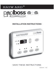
<strong>Aqua</strong> <strong>Logic</strong><br />
<strong>Automation</strong> <strong>and</strong> <strong>Chlorination</strong><br />
(actuators, cell & remote display not included - order separately)<br />
<strong>Installation</strong> Manual<br />
for model<br />
AQL-P-4<br />
G<br />
LDLINE<br />
CON TROLS<br />
www.goldlinecontrols.com<br />
888-921-7665
IMPORTANT SAFETY INSTRUCTIONS<br />
When using this electrical equipment, basic safety precautions should always be<br />
followed, including the following:<br />
• READ AND FOLLOW ALL INSTRUCTIONS<br />
• ! WARNING: Disconnect all AC power during installation.<br />
• ! WARNING: Water in excess of 100 degrees Fahrenheit may be<br />
hazardous to your health.<br />
• ! WARNING: To reduce the risk of injury, do not permit children to<br />
use this product unless they are closely supervised at all times.<br />
• A green colored terminal marked “Earth Ground” is located inside the wiring<br />
compartment. To reduce the risk of electric shock, this terminal must be<br />
connected to the grounding means provided in the electric supply service<br />
panel with a continuous copper wire equivalent in size to the circuit conductors<br />
supplying the equipment.<br />
• One bonding lug for US models (two for Canadian models) is provided on the<br />
external surface. To reduce the risk of electric shock, connect the local<br />
common bonding grid in the area of the swimming pool, spa, or hot tub to<br />
these terminals with an insulated or bare copper conductor not smaller than 8<br />
AWG US / 6 AWG Canada.<br />
• All field installed metal components such as rails, ladders, drains, or other<br />
similar hardware within 3 meters of the pool, spa or hot tub shall be bonded to<br />
the equipment grounding bus with copper conductors not smaller than 8 AWG<br />
US / 6 AWG Canada.<br />
• SAVE THESE INSTRUCTIONS
Table of Contents<br />
Introduction Before You Begin................................................................... 1<br />
<strong>Installation</strong> Steps.................................................................... 2<br />
1. Preparing General Water Chemistry..................................................... 3<br />
Pool/Spa Water Salt.......................................................................................... 4<br />
2. Mounting <strong>Aqua</strong> <strong>Logic</strong> Control Center................................................... 6<br />
Equipment Temperature Sensors........................................................... 6<br />
Optional AQL-CL <strong>Chlorination</strong> Kit........................................ 6<br />
Optional Remote Controls.................................................... 6<br />
Optional Valve Actuators....................................................... 7<br />
3. Plumbing Pool/Spa Configuration........................................................ 8<br />
Turbo Cell............................................................................... 9<br />
Flow Switch............................................................................ 9<br />
4. Electrical Main Service.......................................................................... 10<br />
Wiring Grounding <strong>and</strong> Bonding........................................................ 10<br />
Circuit Breaker <strong>Installation</strong> <strong>and</strong> Wiring......................... ...... 10<br />
General Purpose Outlet........................................................ 11<br />
<strong>Aqua</strong> <strong>Logic</strong> Control Power................................................... 11<br />
High Voltage Pool Equipment.............................................. 12<br />
Low Voltage Wiring............................................................... 13<br />
5. Configuration Configuration Menu............................................................... 19<br />
6. System Startup Before Startup...................................................................... 28<br />
<strong>and</strong> Checkout Heater Checkout................................................................... 28<br />
Service Mode........................................................................ 29<br />
7. Warranty <strong>Aqua</strong> <strong>Logic</strong> Limited Warranty.............................................. 32
Introduction<br />
Before You Begin<br />
What’s Included<br />
Before attempting to install the <strong>Aqua</strong> <strong>Logic</strong> system, check that the following components have been<br />
included in the package:<br />
<strong>Aqua</strong> <strong>Logic</strong> Electronics Unit<br />
(3) Temperature sensors with 15 ft. (5m) cable, hose clamp<br />
What’s NOT Included<br />
Some of the additional items that you may need to complete an installation include:<br />
Circuit breakers<br />
None are included with control—see page 10 <strong>and</strong> inside of door for suitable breakers<br />
Wire<br />
4-conductor cable (electronics unit to remote display/keypad)<br />
Wire/conduit for 100A service from main panel to <strong>Aqua</strong> <strong>Logic</strong><br />
Wire/conduit for filter pump <strong>and</strong> other high voltage loads<br />
Wire for bonding<br />
Miscellaneous<br />
Utility electrical outlet <strong>and</strong> weatherproof cover (for mounting on side of <strong>Aqua</strong> <strong>Logic</strong>)<br />
Mounting hardware (screws, etc.) for mounting <strong>Aqua</strong> <strong>Logic</strong> <strong>and</strong> remote display/keypad<br />
Valves (use st<strong>and</strong>ard <strong>Hayward</strong>, Pentair/Compool, or J<strong>and</strong>y valves)<br />
Additional valve actuators<br />
Accessory Products - Order Separately<br />
AQL-CL<br />
AQL-CL-25FT<br />
AQL-WW-P-4<br />
AQL-SS-6B-x (x=W/G/B)<br />
AQL2-POD<br />
AQL-SS-RF<br />
AQL-BASE-RF<br />
AQL2-BASE-RF<br />
AQL-DIM<br />
GVA-24<br />
V&A-xx<br />
<strong>Chlorination</strong> kit<br />
<strong>Chlorination</strong> kit with 25ft cable<br />
Wired Remote Display (requires AQL-BASE-RF)<br />
Wired Spa Side 6 Function Remote Control, 150ft cable, specify color (white, gray or black)<br />
H<strong>and</strong>held Wireless Waterproof Remote with Charging Station (requires AQL2-BASE-RF)<br />
Wireless Spa Side Remote Control (AQL-BASE-RF required)<br />
Base Receiver<br />
Base Receiver<br />
Light Dimmer Relay<br />
Valve Actuator<br />
Valve & Actuator (xx=1P (1.5” pos. seal), -2P (2” pos. seal)<br />
NOTE: Before installing this product as part of a saline water purification system in a pool or spa using<br />
natural stone for coping or for immediately adjacent patios/decking, a qualified stone installation specialist<br />
should be consulted regarding the appropriate type, installation, sealant (if any) <strong>and</strong> maintenance of stone<br />
used around a saline pool with electronic chlorine generator in your particular location <strong>and</strong> circumstances.<br />
1
<strong>Installation</strong> Steps<br />
Details on each installation step are presented on the following pages:<br />
1. Prepare the pool water (page 3)<br />
General Water Chemistry<br />
Salt<br />
2. Mounting the equipment (page 6)<br />
<strong>Aqua</strong> <strong>Logic</strong> main unit<br />
Remote display/keypad (optional)<br />
Temperature sensors<br />
Valve actuators (if applicable)<br />
3. Plumbing (page 8)<br />
General Pool Equipment<br />
Turbo Cell<br />
Flow Switch<br />
4. Electrical Wiring (page 10)<br />
Main service<br />
Grounding <strong>and</strong> bonding<br />
Circuit breakers<br />
<strong>Aqua</strong> <strong>Logic</strong> control power<br />
High Voltage pool equipment<br />
Low voltage wiring (temperature sensors, flow switch, etc.)<br />
5. <strong>Aqua</strong> <strong>Logic</strong> control configuration (page 19)<br />
6. System Startup <strong>and</strong> checkout (page 28)<br />
2
1. Preparing Pool/Spa Water<br />
General Water Chemistry<br />
Salt is required only if you are using the chlorinator features on the <strong>Aqua</strong> <strong>Logic</strong> Control. If you are NOT<br />
using the chlorinator, it is recommended that you follow all of the other chemistry recommendations besides<br />
salt. Refer to the description of the <strong>Aqua</strong> <strong>Logic</strong> configuration menu for information on enabling/<br />
disabling the chlorinator (see page 19).<br />
Water Chemistry<br />
The table below summarizes the levels that are recommended by the Association of Pool <strong>and</strong> Spa Professionals<br />
(APSP). The only special requirements for the <strong>Aqua</strong> <strong>Logic</strong> are the salt level <strong>and</strong> stabilizer.<br />
Saturation index<br />
The saturation index (Si) relates to the calcium <strong>and</strong> alkalinity in the water <strong>and</strong> is an indicator of the pool<br />
water “balance”. Your water is properly balanced if the Si is 0 ±0.2. If the Si is below -0.2, the water is<br />
corrosive <strong>and</strong> plaster pool walls will be dissolved into the water. If the Si is above +0.2, scaling <strong>and</strong><br />
staining will occur. Use the chart below to determine the saturation index.<br />
Si = pH + Ti + Ci + Ai - 12.1<br />
ºC ºF Ti<br />
12<br />
16<br />
19<br />
24<br />
29<br />
34<br />
39<br />
53<br />
60<br />
66<br />
76<br />
84<br />
94<br />
103<br />
.3<br />
.4<br />
.5<br />
.6<br />
.7<br />
.8<br />
.9<br />
Calcuim<br />
Hardness<br />
Ci<br />
Total<br />
Alkalinity Ai<br />
1.5 1.9<br />
1.6 2.0<br />
1.7 2.1<br />
1.8 2.2<br />
1.9 2.3<br />
2.0 2.4<br />
2.1 2.5<br />
2.2 2.6<br />
2.4 2.8<br />
2.5 2.9<br />
75 75<br />
100 100<br />
125 125<br />
150 150<br />
200 200<br />
250 250<br />
300 300<br />
400 400<br />
600 600<br />
800 800<br />
How to use: Measure pool pH, temperature, calcium hardness,<br />
<strong>and</strong> total alkalinity. Use the chart above to determine Ti, Ci,<strong>and</strong><br />
Ai from your measurements. Insert values of pH, Ti, Ci <strong>and</strong> Ai<br />
into the above equation. If Si equals .2 or more, scaling <strong>and</strong><br />
staining may occur. If Si equals -.2 or less corrosion or irritation<br />
may occur.<br />
-.2 0 .2<br />
CORROSIVE<br />
SCALING<br />
OK<br />
3
The pool’s chemistry must be balanced BEFORE activating the <strong>Aqua</strong> <strong>Logic</strong>’s optional chlorinator function.<br />
NOTE: If the pool does not have new water, add metal remover <strong>and</strong> non-copper based algaecide<br />
to the pool, per manufacturer’s instructions. This ensures a quick, troublefree transfer to the <strong>Aqua</strong> <strong>Logic</strong><br />
system.<br />
Salt (When using optional chlorinator function - requires AQL-CL chlorination kit)<br />
Salt Level<br />
Use the chart below to determine how much salt in pounds or (Kgs) should be added to reach the recommended<br />
levels. Use the equations on the following page (measurements are in feet/gallons <strong>and</strong> meters/<br />
liters) if pool size is unknown.<br />
The operating salt level is between 2700-3400 PPM (parts per million) with 3200 PPM being optimal.<br />
Before adding any salt, test the salt level. This is especially important for retrofit installation to older pools<br />
where all of the chlorine added to the pool over time is ending up as salt. If the level is low, determine the<br />
number of gallons in the pool <strong>and</strong> add salt according to the chart below. A low salt level will reduce the<br />
efficiency of the sanitization <strong>and</strong> result in low chlorine production. A high salt level can cause the <strong>Aqua</strong><br />
<strong>Logic</strong> to stop chlorinating. The salt in your pool/spa is constantly recycled <strong>and</strong> the loss of salt throughout<br />
the swimming season should be minimal. This loss is due primarily to the addition of water because of<br />
splashing, backwashing, or draining (because of rain). Salt is not lost due to evaporation.<br />
Current salt<br />
level<br />
ppm<br />
0<br />
200<br />
400<br />
600<br />
800<br />
1000<br />
1200<br />
1400<br />
1600<br />
1800<br />
2000<br />
2200<br />
2400<br />
2600<br />
2800<br />
3000<br />
POUNDS <strong>and</strong> (Kg) OF SALT NEEDED FOR 3200 PPM<br />
Gallons <strong>and</strong> (Liters) of Pool/Spa water<br />
8,000 10,000 12,000 14,000 16,000 18,000 20,000 22,000 24,000 26,000 28,000 30,000 32,000 34,000 36,000 38,000 40,000<br />
(30,000) (37,500) (45000) (52,500) (60,000) (67,500) (75,000) (82,500) (90,000) (97,500) (105,000)(112,500) (120,000)(127,500)(135,000)<br />
(142,500)(150,000)<br />
213 267<br />
(97) (121)<br />
200 250<br />
(91) (114)<br />
187 233<br />
(85) (106)<br />
173 217<br />
(79) (98)<br />
160 200<br />
(73) (91)<br />
147 183<br />
(67) (83)<br />
133 167<br />
(61) (76)<br />
120 150<br />
(55) (68)<br />
107 133<br />
(48) (61)<br />
93 117<br />
(42) (53)<br />
80 100<br />
(36) (45)<br />
67 83<br />
(30) (38)<br />
53 67<br />
(24) (30)<br />
40 50<br />
(18) (23)<br />
27 33<br />
(12) (15)<br />
13 17<br />
(6) (8)<br />
320<br />
(145)<br />
300<br />
(136)<br />
280<br />
(127)<br />
260<br />
(118)<br />
240<br />
(109)<br />
220<br />
(100)<br />
200<br />
(91)<br />
180<br />
(82)<br />
160<br />
(73)<br />
140<br />
(64)<br />
120<br />
(55)<br />
100<br />
(45)<br />
80<br />
(36)<br />
60<br />
(27)<br />
40<br />
(18)<br />
20<br />
(9)<br />
373<br />
(170)<br />
350<br />
(159)<br />
327<br />
(148)<br />
303<br />
(138)<br />
280<br />
(127)<br />
257<br />
(117)<br />
233<br />
(106)<br />
210<br />
(95)<br />
187<br />
(85)<br />
163<br />
(74)<br />
140<br />
(64)<br />
117<br />
(53)<br />
93<br />
(42)<br />
(32)<br />
47<br />
(21)<br />
23<br />
(11)<br />
427<br />
(194)<br />
400<br />
(182)<br />
373<br />
(170)<br />
347<br />
(158)<br />
320<br />
(145)<br />
293<br />
(133)<br />
267<br />
(121)<br />
240<br />
(109)<br />
213<br />
(97)<br />
187<br />
(85)<br />
160<br />
(73)<br />
133<br />
(61)<br />
107<br />
(48)<br />
80<br />
(36)<br />
53<br />
(24)<br />
27<br />
(12)<br />
480<br />
(218) (242)<br />
450<br />
(205)<br />
420<br />
(191)<br />
390<br />
(177)<br />
360<br />
(164)<br />
330<br />
(150)<br />
300<br />
(136)<br />
270<br />
(123)<br />
240<br />
(109)<br />
210<br />
(95)<br />
180<br />
(82)<br />
150<br />
(68)<br />
120<br />
(55)<br />
90<br />
(41)<br />
60<br />
(27)<br />
30<br />
(14)<br />
500<br />
(227)<br />
467<br />
(212)<br />
433<br />
(197)<br />
400<br />
(182)<br />
367<br />
(167)<br />
333<br />
(152)<br />
300<br />
(136)<br />
267<br />
(121)<br />
233<br />
(106)<br />
200<br />
(91)<br />
167<br />
(76)<br />
133<br />
(61)<br />
100<br />
(45)<br />
67<br />
(30)<br />
33<br />
(15)<br />
587 640 693 747 800 854 907 960<br />
1067<br />
(267) (291) (315) (339) (364) (388) (412) (436) (460) (484)<br />
550 600 650 700 750 800 850 900 950 1000<br />
(250) (273) (295) (318) (341) (363) (385) (408) (430) (453)<br />
513 560 607 653 700 747 793 840 887 933<br />
(233) (255) (276) (297) (318) (339) (360) (382) (403) (424)<br />
477 520 563 607 650 693 737 780 823 867<br />
(217) (236) (256) (276) (297) (317) (337) (358) (378) (398)<br />
440 480 520 560 600 640 680 720 760 800<br />
(200) (218) (236) (255) (273) (291) (310) (328) (346) (364)<br />
403 440 477 513 550 587 623 660 697 733<br />
(183) (200) (217) (233) (250) (267) (283) (300) (317) (333)<br />
367 400 433 467 500 533 567 600 633 667<br />
(167) (182) (197) (212) (227) (243) (258) (274) (289) (304)<br />
330 360 390 420 450 480 510 540 570 600<br />
(150) (164) (177) (191) (205) (218) (232) (246) (259) (263)<br />
293 320 347 373 400 427 453 480 507 533<br />
(133) (145) (158) (170) (182) (195) (207) (219) (231) (243)<br />
257 280 303 327 350 373 397 420 443 467<br />
(117) (127) (138) (148) (159) (169) (180) (190) (201) (211)<br />
220 240 260 280 300 320 340 360 380 400<br />
(100) (109) (118) (127) (136) (145) (154) (163) (172) (181)<br />
183 200 217 233 250 267 283 300 317 333<br />
(83) (91) (98) (106) (114) (121) (129) (137) (144) (152)<br />
147 160 173 187 200 213 227 240 253 267<br />
(67) (73) (79) (85) (91) (98) (104) (110) (117) (123)<br />
110 120 130 140 150 160 170 180 190 200<br />
(50) (55) (59) (64) (68) (73) (77) (81) (86) (90)<br />
73 80 87 93 100 107 113 120 127 133<br />
(33) (36) (39) (42) (45) (48) (51) (54) (57) (60)<br />
37 40 43 47 50 53 57 60 63 67<br />
(17) (18) (20) (21) (23) (24) (26) (27) (29) (30)<br />
3200 Ideal Ideal Ideal Ideal Ideal Ideal Ideal<br />
Ideal Ideal<br />
3400 OK<br />
Ideal Ideal Ideal Ideal Ideal Ideal Ideal Ideal<br />
OK OK OK OK OK OK OK OK OK OK OK OK OK OK OK OK<br />
Dilute Dilute<br />
Dilute Dilute Dilute Dilute Dilute Dilute Dilute Dilute<br />
3600+ Dilute Dilute Dilute Dilute Dilute Dilute Dilute<br />
4
Pool Sizing Formula<br />
Gallons<br />
(pool size in feet)<br />
Rectangular Length x Width x<br />
Average Depth x 7.5<br />
Round<br />
Diameter x Diameter x<br />
Average Depth x 5.9<br />
Liters<br />
(pool size in meters)<br />
Length x Width x<br />
Average Depth x 1000<br />
Diameter x Diameter x<br />
Average Depth x 785<br />
Oval<br />
Length x Width x<br />
Average Depth x 6.7<br />
Length x Width x<br />
Average Depth x 893<br />
Type of Salt to Use<br />
It is important to use only sodium chloride (NaCl) salt that is greater than 99.0% pure. This can be found<br />
at most pool stores in 40-80 lb. bags labeled “for use in swimming pools”. Alternatively, use common food<br />
quality or water softener salt that is at least 99.0% pure. It is also acceptable to use water conditioning salt<br />
pellets, however, it will take longer for them to dissolve. Do not use rock salt, or salt with more than 1%<br />
of yellow prussiate of soda, salt with anti-caking additives, or iodized salt.<br />
How to Add Salt<br />
For new plaster pools, wait 10-14 days before adding salt to allow the plaster to cure. Turn the circulating<br />
pump on <strong>and</strong> add salt directly into the pool. Brush the salt around to speed up the dissolving process—do<br />
not allow salt to pile up on the bottom of the pool. Run the filter pump for 24 hours with the suction coming<br />
from the main drain (use pool vacuum if there is no main drain) to allow the salt to evenly disperse throughout<br />
the pool. The salt display may take 24 hours to respond to the change in salt concentration.<br />
Always check stabilizer (cyanuric acid), when checking salt. These levels will most likely decline together.<br />
Use the chart below to determine how much stabilizer must be added to raise the level to 80 ppm.<br />
Current<br />
Stabilizer<br />
Level (ppm)<br />
0 ppm<br />
10 ppm<br />
20 ppm<br />
30 ppm<br />
40 ppm<br />
50 ppm<br />
60 ppm<br />
70 ppm<br />
80 ppm<br />
8,000<br />
(30000)<br />
5.3<br />
(3.6)<br />
4.7<br />
(3.2)<br />
4.0<br />
(2.7)<br />
3.3<br />
(2.3)<br />
2.7<br />
(1.8)<br />
2.0<br />
(1.4)<br />
1.3<br />
(.91)<br />
0.7<br />
(.45)<br />
10,000<br />
(37500)<br />
6.7<br />
(4.3)<br />
5.8<br />
(3.7)<br />
4.2<br />
(2.7)<br />
3.3<br />
(2.1)<br />
2.5<br />
(1.6)<br />
1.7<br />
(1.1)<br />
0.8<br />
(.54)<br />
12,000<br />
(45000)<br />
8.0<br />
(3.6)<br />
7.0<br />
(3.2)<br />
6.0<br />
(2.7)<br />
5.0<br />
(2.3)<br />
4.0<br />
(1.8)<br />
3.0<br />
(1.4)<br />
2.0<br />
(.91)<br />
1.0<br />
(.45)<br />
14,000<br />
(52500)<br />
9.4<br />
(4.3)<br />
8.2<br />
(3.7)<br />
7.0<br />
(3.2)<br />
5.9<br />
(2.7)<br />
4.7<br />
(2.1)<br />
3.5<br />
(1.6)<br />
2.3<br />
(1.1)<br />
1.2<br />
(.54)<br />
POUNDS <strong>and</strong> (Kg) OF STABILIZER (CYANURIC ACID) NEEDED FOR 80 PPM<br />
16,000<br />
(60000)<br />
10.7<br />
(4.9)<br />
9.4<br />
(4.3)<br />
8.0<br />
(3.6)<br />
6.7<br />
(3.0)<br />
5.4<br />
(2.4)<br />
4.0<br />
(1.8)<br />
2.7<br />
(1.2)<br />
1.4<br />
(.64)<br />
18,000<br />
(67500)<br />
12.0<br />
(5.4)<br />
10.5<br />
(4.8)<br />
9.0<br />
(2.2)<br />
7.5<br />
(3.4)<br />
6.0<br />
(2.7)<br />
4.5<br />
(2.0)<br />
3.0<br />
(1.4)<br />
1.5<br />
(.68)<br />
Gallons <strong>and</strong> (Liters) of Pool/Spa water<br />
20,000 22,000 24,000 26,000<br />
(75000) (82500) (90000) (97500)<br />
13.4<br />
(6.1)<br />
11.7<br />
(5.3)<br />
10.0<br />
(4.5)<br />
8.4<br />
(3.8)<br />
6.7<br />
(3.0)<br />
5.0<br />
(2.3)<br />
3.3<br />
(1.5)<br />
1.7<br />
(.77)<br />
14.7<br />
(6.7)<br />
12.9<br />
(5.9)<br />
11.0<br />
(5.0)<br />
9.2<br />
(4.2)<br />
7.4<br />
(3.3)<br />
5.5<br />
(2.5)<br />
3.7<br />
(1.7)<br />
1.8<br />
(.82)<br />
16.0<br />
(7.3)<br />
14.0<br />
(6.4)<br />
12.0<br />
(5.4)<br />
10.0<br />
(4.5)<br />
8.0<br />
(3.6)<br />
6.0<br />
(2.7)<br />
4.0<br />
(1.8)<br />
2.0<br />
(.91)<br />
15.2<br />
(6.9)<br />
13.0<br />
(5.9)<br />
10.8<br />
(4.9)<br />
8.7<br />
(3.9)<br />
6.5<br />
(2.9)<br />
4.3<br />
(2.0)<br />
2.2<br />
(1.0)<br />
28,000<br />
(105000)<br />
18.7<br />
(8.5)<br />
16.4<br />
(7.4)<br />
14.0<br />
(6.4)<br />
11.7<br />
(5.2)<br />
9.3<br />
(4.2)<br />
7.0<br />
(3.2)<br />
4.7<br />
(2.1)<br />
2.3<br />
(1.1)<br />
30,000 32,000 34,000 36,000<br />
(112500)(120000)(127500)(135000)<br />
20.0<br />
(9.1)<br />
17.2<br />
(8.0)<br />
15.0<br />
(6.8)<br />
12.5<br />
(5.6)<br />
10.0<br />
(4.5)<br />
7.5<br />
(3.4)<br />
5.0<br />
(2.3)<br />
2.5<br />
(1.2)<br />
21.3<br />
(9.7)<br />
18.7<br />
(8.5)<br />
16.0<br />
(7.2)<br />
13.3<br />
(6.0)<br />
10.7<br />
(4.8)<br />
8.0<br />
(3.6)<br />
5.3<br />
(2.4)<br />
2.7<br />
(1.2)<br />
22.7<br />
(10.3)<br />
19.8<br />
(9.0)<br />
0.0 0.0 0.0 0.0 0.0 0.0 0.0 0.0 0.0 0.0 0.0 0.0 0.0 0.0 0.0 0<br />
14.2<br />
(6.3)<br />
8.5<br />
(3.9)<br />
5.7<br />
(2.6)<br />
2.8<br />
(1.3)<br />
21.0<br />
(9.5)<br />
18.0<br />
(8.1)<br />
15.0<br />
(6.7)<br />
12.0<br />
(5.4)<br />
9.0<br />
(4.1)<br />
3.0<br />
(1.3)<br />
38,<br />
(142<br />
2<br />
(1<br />
2<br />
(1<br />
1<br />
(8<br />
1<br />
(7<br />
12<br />
(5<br />
9<br />
(4<br />
6<br />
(2<br />
3<br />
(1<br />
5
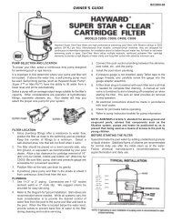
2. Mounting the Equipment<br />
<strong>Aqua</strong> <strong>Logic</strong> Control Center<br />
The <strong>Aqua</strong> <strong>Logic</strong> is contained in a raintight enclosure that is suitable for outdoor mounting. The control must<br />
be mounted a minimum of 5 ft. (2 meters) horizontal distance from the pool/spa (or more, if local codes<br />
require). The Control Center is designed to mount vertically on a flat surface with the knockouts facing<br />
downward. Because the enclosure also acts as a heat sink (disperses heat from inside the box), it is<br />
important not to block the four sides of the control. Do not mount the <strong>Aqua</strong> <strong>Logic</strong> inside a panel or tightly<br />
enclosed area.<br />
When selecting a location, note that the st<strong>and</strong>ard cables supplied with the Turbo Cell, flow switch, temperature<br />
sensors, <strong>and</strong> valve actuators (if applicable) are all 15 ft. (5m) long. Call the Goldline Service<br />
Dept. (888-921-7665) for information regarding longer cables.<br />
Temperature Sensors<br />
Three sensors are included with the <strong>Aqua</strong> <strong>Logic</strong>. A water sensor <strong>and</strong> an air sensor must be installed at all<br />
times for proper operation. A solar sensor is required if the solar function or “dual equipment” is enabled.<br />
Water Sensor<br />
This sensor is used to measure the pool/spa temperature <strong>and</strong> is installed in the filtration plumbing after the<br />
filter but before either the solar or conventionally fueled heaters—refer to the plumbing overview diagram.<br />
1. Drill a 3/8” (10mm) diameter hole in the PVC piping <strong>and</strong> remove all chips <strong>and</strong> burrs.<br />
2. Insert sensor until O-ring collar sits flush on the hole.<br />
3. Position hose clamp over the sensor <strong>and</strong> gently tighten until O-ring makes an adequate seal. Do not<br />
overtighten.<br />
4. For maximum temperature accuracy, cover the sensor <strong>and</strong> 3” (6cm) of pipe on either side with<br />
insulation <strong>and</strong> white paint.<br />
Air Sensor<br />
Mount the air sensor outdoors. ! IMPORTANT: Mount the air sensor out of direct sunlight.<br />
Solar Sensor (Spa Sensor if using “Dual Equipment”)<br />
For solar applications, mount the sensor near the solar collector array so that it is exposed to the same<br />
sunlight as the collectors. For Dual Equipment applications, mount the sensor after the spa filter but before<br />
the heater (see page 8). Use additional cable (20 AWG) if necessary.<br />
Optional AQL-CL <strong>Chlorination</strong> Kit<br />
The AQL-P4 requires the use of the AQL-CL or AQL-CL-25FT chlorination kit when using the chlorinator<br />
function. This kit contains a Turbo Cell, cell unions <strong>and</strong> flow switch. Refer to pages 9 <strong>and</strong> 18 for<br />
plumbing <strong>and</strong> wiring instructions.<br />
Optional Remote Controls<br />
Goldline offers a variety of wired <strong>and</strong> wireless remote control options for the <strong>Aqua</strong> <strong>Logic</strong>. Each model<br />
gives you the ability to control your pool’s functions from a remote location, away from the Control Center.<br />
Wired Remote Controls<br />
Up to 3 wired remote controls can be installed. See page 17 for wiring information.<br />
AQL-WW-P4<br />
The AQL-WW-P4 display/keypad must be mounted indoors or in a weather protected area (rain should<br />
6
never touch the unit). The display/keypad is designed to mount onto a st<strong>and</strong>ard electrical utility box (same<br />
box as a single light switch, ideal for new construction) or can be mounted directly onto any wall surface.<br />
When selecting a location, note that the wire to the <strong>Aqua</strong> <strong>Logic</strong> main unit must be less than 500’ long. Refer<br />
to the remote’s installation instructions as well as the steps below:<br />
1. Remove display/keypad baseplate from the cover by lifting up on the cover at the lower end of the<br />
keypad. See diagram below.<br />
2. Screw the baseplate in the desired position (screws supplied by installer).<br />
Remote Keypad<br />
3. See “Electrical Wiring” (page 17) for instructions on running the cable from the <strong>Aqua</strong> <strong>Logic</strong> main<br />
unit to the remote display/keypad.<br />
AQL-SS-6B-x (x=W, G or B for White, Gray or Black)<br />
The AQL-SS-6B is a double insulated, waterproof device which is intended for installation at the water's<br />
edge. The remote control comes with an attached 150’ cable <strong>and</strong> is typically installed at the tile-line of the<br />
spa wall, or in the deck, within arm's reach of a pool/spa occupant. Refer to the AQL-SS-6B installation<br />
manual for specific mounting <strong>and</strong> wiring information.<br />
Wireless Remote Controls<br />
A single Base Receiver must be installed on the <strong>Aqua</strong> <strong>Logic</strong> in order to use the AQL-SS-RF wireless spa<br />
side remote control. With the Base Receiver installed, there is no limit on the number of wireless remotes<br />
that can used. The maximum distance between the wireless remote <strong>and</strong> the base receiver on the <strong>Aqua</strong><br />
<strong>Logic</strong> main control unit is 400 feet (120m) line of sight or 200 feet (60m) through walls, etc. If in doubt<br />
about the distance, test operation before installing the remote.<br />
The wireless remotes require the user to run the “Teach Wireless” routine in the Settings Menu. This<br />
information can be found in the <strong>Aqua</strong> <strong>Logic</strong> Operation Manual <strong>and</strong> the owner’s manual of each remote.<br />
AQL-BASE-RF/AQL2-BASE-RF Base Receiver<br />
This optional base receiver must be installed if the wireless spa side remote (AQL-SS-RF) is used. To<br />
install the base receiver, remove the knockout on the upper left side of the <strong>Aqua</strong> <strong>Logic</strong> main control unit,<br />
insert the base receiver, <strong>and</strong> then tighten the nut from the inside. Also refer to the Base Receiver manual<br />
<strong>and</strong> the diagram on page 17.<br />
AQL-SS-RF Wireless Spa Side Remote Control<br />
The AQL-SS-RF is a waterproof portable remote control that is designed to be used in <strong>and</strong> around the<br />
pool/spa area. The unit floats <strong>and</strong> can be left in the pool/spa water for easy access.<br />
Optional Valve Actuators<br />
If using the actuators supplied with the <strong>Aqua</strong> <strong>Logic</strong>—note that the internal cams in the actuator may have<br />
to be adjusted depending on the way the actuator is mounted on the valve <strong>and</strong> the desired valve action.<br />
RETURN<br />
push up here<br />
to remove cover<br />
SUCTION<br />
OUT<br />
OUT<br />
IN<br />
IN<br />
IN<br />
(Common)<br />
7<br />
OUT<br />
(Common)
3. Plumbing<br />
“St<strong>and</strong>ard” Pool/Spa system configuration<br />
These systems use a single filter pump <strong>and</strong> filter. Pool or spa operation is controlled by two 3-way valves<br />
(suction <strong>and</strong> return). Refer to the diagram below.<br />
HIGH VOLTAGE<br />
LIGHTS<br />
High Voltage Relays<br />
Filter Pump<br />
Lights<br />
Aux 1<br />
Aux 2<br />
Valve Outputs<br />
Pool/Spa Suction<br />
Pool/Spa Return<br />
Valve 3<br />
TRANSFORMER<br />
FIBER OPTIC<br />
LIGHT SOURCE<br />
LOW VOLTAGE<br />
LIGHTS<br />
COLOR WHEEL<br />
SOLAR<br />
TEMPERATURE<br />
SENSOR<br />
CHECK VALVE<br />
(prevents draining<br />
of raised spas)<br />
POOL/SPA SUCTION<br />
VALVE<br />
FILTER<br />
PUMP<br />
MANUAL<br />
VALVE<br />
FILTER<br />
SOLAR BOOST<br />
PUMP<br />
CHECK<br />
VALVE<br />
SOLAR<br />
VALVE<br />
CHECK<br />
VALVE<br />
HEATER<br />
CELL<br />
FLOW<br />
SWITCH<br />
POOL VACUUM<br />
VALVE<br />
MANUAL<br />
VALVE<br />
POOL/SPA<br />
TEMPERATURE<br />
SENSOR<br />
HEATER<br />
BYPASS<br />
VALVE<br />
(manual)<br />
MANUAL<br />
VALVE<br />
POOL/SPA<br />
RETURN<br />
VALVE<br />
POOL SWEEP<br />
BOOST PUMP<br />
TWO-WAY<br />
VALVE<br />
ENERGY<br />
FILTER<br />
SPA<br />
BLOWER<br />
WATER<br />
FEATURE<br />
CHECK<br />
VALVE<br />
VALVE<br />
(prevents draining<br />
of raised spas)<br />
WATER<br />
FEATURE<br />
PUMP<br />
ISOLATED<br />
WATER<br />
FEATURE<br />
PUMP<br />
SPA<br />
SPA JET<br />
PUMP<br />
POP-UP<br />
IN-FLOOR<br />
CLEANER<br />
SUCTION<br />
CLEANER<br />
SKIM<br />
MAIN<br />
DRAIN<br />
ENERGY<br />
SAVER<br />
PRESSURE<br />
CLEANER<br />
POP-UP<br />
SPILLOVER<br />
POOL<br />
OVERFLOW<br />
POP-UP<br />
POP-UP<br />
RETURN<br />
JET<br />
NON-BOOST<br />
PRESSURE<br />
CLEANER<br />
VALVE<br />
WATER<br />
FEATURE<br />
PUMP<br />
WATER<br />
FEATURE<br />
PRESSURE<br />
CLEANER<br />
Some important notes regarding the <strong>Aqua</strong> <strong>Logic</strong> control of St<strong>and</strong>ard Pool/Spa systems:<br />
Pool/Spa Setup<br />
In Pool/Spa Config., select:<br />
Pool <strong>and</strong> Spa<br />
1. The <strong>Aqua</strong> <strong>Logic</strong> can be programmed to accommodate spa spillover, if desired.<br />
2. A conventional heater (gas or heat pump) <strong>and</strong> solar can be used to heat both the pool <strong>and</strong> the spa.<br />
3. If the chlorinator cell is plumbed prior to the pool/spa return valve, then both the pool <strong>and</strong> the spa<br />
can be chlorinated<br />
4. The water sensor should be installed prior to any heater or solar <strong>and</strong> will display either the pool or<br />
the spa temperature, depending on the current operation of the pool. The temperature will only be<br />
displayed when the filter pump is running.<br />
5. If any water feature or pressure side cleaner boost pumps are used, be sure to enable the “interlock”<br />
feature (see “Configuration Menu” for details) to ensure that the pumps operate only when the<br />
filter pump is on <strong>and</strong> the system is in the “pool only” operating mode.<br />
6. The plumbing diagram above is intended to be used as a general guideline <strong>and</strong> is not a complete<br />
plumbing schematic for the pool.<br />
7. The air sensor must be installed if the freeze protection feature is enabled for the filter, valves or aux<br />
outputs or if the chlorinator is enabled.<br />
8
Turbo Cell (supplied with AQL-CL chlorination kit)<br />
The Turbo Cell (used for chlorine generation) should be plumbed AFTER the filter <strong>and</strong> heater. If installed<br />
on a pool/spa combination system, the cell should be plumbed BEFORE the pool/spa return valve in order<br />
to allow proper chlorination of both the pool <strong>and</strong> the spa. Refer to plumbing diagram below:<br />
12”<br />
min<br />
Flow switch before cell<br />
Flow switch after cell<br />
The cell may be mounted vertically or horizontally, <strong>and</strong> water can move in either direction through the cell.<br />
Install using the 2" unions provided. Tighten unions BY HAND for a watertight seal. For systems with<br />
1½“ plumbing use adaptors (provided by installer).<br />
Flow Switch (supplied with AQL-CL chlorination kit)<br />
The flow switch must be plumbed in the same section of plumbing as the Turbo Cell. The flow switch is a<br />
safety device that ensures that water is flowing through the cell before the <strong>Aqua</strong> <strong>Logic</strong> starts to generate<br />
chlorine. Failure to properly install the flow switch can result in explosive gases accumulating in the pool<br />
plumbing system.<br />
! IMPORTANT: There must be at least a 12" (30cm) straight pipe run before (upstream)<br />
the flow switch. If the switch is plumbed after the cell, the cell can by counted as the 12" (30cm)<br />
of straight pipe.<br />
! IMPORTANT: To ensure proper operation, verify that the arrow on the flow switch points<br />
in the direction of water flow.<br />
9
4. Electrical Wiring<br />
Remote Keypad<br />
Heater Output<br />
Sensor Inputs<br />
Valve Connectors<br />
Cell<br />
x<br />
“Local” Display<br />
Flow Switch<br />
Subpanel<br />
High Voltage<br />
Relays<br />
Control Power<br />
Input<br />
The <strong>Aqua</strong> <strong>Logic</strong> Control Center requires both high <strong>and</strong> low voltage connections. Low voltage connections<br />
will be made to actuators, sensors, remote keypad, etc. High voltage connections will be made to pumps,<br />
lights, etc., as well as providing direct input power to the Control Center. Always:<br />
-Ensure that Power is disconnected prior to doing any wiring<br />
-Follow all local <strong>and</strong> NEC (CEC if applicable) codes<br />
-Use copper conductors only<br />
Main Service (Power to the Circuit Breaker Subpanel)<br />
The <strong>Aqua</strong> <strong>Logic</strong> circuit breaker subpanel is rated for 100A service. Run properly rated conductors (L1,<br />
L2, N, <strong>and</strong> ground) from the primary house electrical panel to the main power connections on the <strong>Aqua</strong><br />
<strong>Logic</strong> circuit breaker base. The connection at the main house panel should be to a 240VAC circuit<br />
breaker rated at 100A maximum.<br />
Grounding <strong>and</strong> Bonding<br />
Connect a ground wire from the primary electrical panel to the <strong>Aqua</strong> <strong>Logic</strong> ground bus bar. Also ground<br />
each piece of high voltage (120 or 240VAC) equipment that is connected to the <strong>Aqua</strong> <strong>Logic</strong> control relays<br />
or circuit breakers. The <strong>Aqua</strong> <strong>Logic</strong> should also be connected to the pool bonding system by an 8AWG<br />
(6AWG for Canada) wire. A lug for bonding (2 for Canada) is provided on the outside/bottom of the<br />
<strong>Aqua</strong> <strong>Logic</strong> enclosure.<br />
Circuit Breaker <strong>Installation</strong> <strong>and</strong> Wiring<br />
Circuit breakers are to be supplied by the installer. Refer to the circuit breaker chart on the following page<br />
for a list of suitable circuit breakers that can be used. Follow the code <strong>and</strong> the circuit breaker manufacturer’s<br />
rating requirements regarding the size <strong>and</strong> temperature rating for wiring. Note that some pool equipment<br />
may be required to be connected to ground fault circuit breakers—check local <strong>and</strong> NEC (CEC) codes.<br />
10
SUITABLE LISTED BREAKERS<br />
Manufacturer Single Double Twin Quad<br />
GFCB Filler Plates<br />
Cutler-Hammer<br />
Murray<br />
Siemens<br />
Square D<br />
Thomas & Betts<br />
BR<br />
MP-T<br />
QP<br />
HOM<br />
TB<br />
BR<br />
MP-T<br />
QP<br />
HOM<br />
TB<br />
BRD<br />
MH-T<br />
QT<br />
HOMT<br />
TBBD<br />
BRD<br />
MH-T<br />
QT<br />
HOMT<br />
TBBQ<br />
GFCB<br />
MP-GT<br />
QPF<br />
HOM<br />
GFB<br />
BRFP<br />
LX100FP<br />
QF3<br />
HOMFP<br />
FP-1C-TB<br />
General Purpose Outlet<br />
If desired, a duplex receptacle with weatherproof cover (supplied by installer) may be installed in the<br />
knockouts on the lower right side of the <strong>Aqua</strong> <strong>Logic</strong> enclosure. Per code, the receptacle should be a<br />
GFCI type. Alternatively, connect a st<strong>and</strong>ard receptacle to a GFCB.<br />
<strong>Aqua</strong> <strong>Logic</strong> Control Power<br />
The <strong>Aqua</strong> <strong>Logic</strong> requires 120VAC, 2A power to operate the control logic circuits <strong>and</strong> the chlorinator.<br />
This power should be connected to one of the circuit breakers.<br />
! WARNING: 120VAC only (permanent damage if connected to 240V)<br />
120, 2VA<br />
Factory<br />
Prewired<br />
Field<br />
Wired<br />
11
High Voltage (120/240V) Pool Equipment<br />
All <strong>Aqua</strong> <strong>Logic</strong> relays are double pole (they make/break both “legs” of 240V circuits) <strong>and</strong> are rated at<br />
3HP/30A at 240V (1½HP/30A at 120V). Refer to the diagram below for typical relay wiring.<br />
240 VAC<br />
Load<br />
120 VAC<br />
Load<br />
120 VAC<br />
Load<br />
Wiring relays for 240 VAC<br />
Pool Equipment<br />
Wiring relays for 120 VAC<br />
Pool Equipment<br />
Wiring GFCB for 120 V<br />
Pool Equipment<br />
! WARNING: Do not use the <strong>Aqua</strong> <strong>Logic</strong> to control an automatic pool cover. Swimmers<br />
may become entrapped underneath the cover.<br />
Two speed filter pump: Requires 2 relays (FILTER plus one of the AUX relays) for proper operation of<br />
both speeds. ! IMPORTANT: Be sure to follow the wiring diagram below AND to configure<br />
the control logic according to the instructions on page 21.<br />
Lo Speed<br />
Hi Speed<br />
Common<br />
Ground<br />
2-Speed<br />
Filter<br />
Pump<br />
N<br />
L2<br />
L1<br />
G<br />
Lights: A ground fault circuit breaker must be used to supply power for high voltage pool/spa lighting.<br />
Low voltage lights will require an external transformer. For lighting systems that have both a light source<br />
<strong>and</strong> color wheel, connect the light source to the “Lights” relay <strong>and</strong> then connect the color wheel to one of<br />
the AUX outputs.<br />
12
Low Voltage Wiring<br />
Valve Actuators<br />
The <strong>Aqua</strong> <strong>Logic</strong> can control up to three automatic valve actuators. Two of the valve outputs are dedicated<br />
to the pool/spa suction (Valve2) <strong>and</strong> return (Valve1) valves. Valve3 is for general purpose use (solar,<br />
water feature, in-floor cleaner, etc.).<br />
For installations with solar heating, Goldline offers the AQ-SOL-KIT-xx solar kit that contains a valve,<br />
actuator, <strong>and</strong> extra temperature sensor. The “xx” indicates the valve type from the 3 choices below:<br />
-1P 1.5” Positive Seal<br />
-2P 2” Positive Seal<br />
The <strong>Aqua</strong> <strong>Logic</strong> is compatible with st<strong>and</strong>ard valve actuators manufactured by <strong>Hayward</strong>, Pentair/Compool,<br />
<strong>and</strong> J<strong>and</strong>y. See diagram on page 10 for the location of valve connectors.<br />
Heater Control<br />
The <strong>Aqua</strong> <strong>Logic</strong> provides a set of low voltage dry contacts that can be connected to most gas heaters or<br />
heat pumps with 24V control circuits. Refer to the diagram below for a generic connection. The manuals<br />
supplied with most heaters also include specific wiring instructions for connecting the heater to an external<br />
control (usually identified as “2-wire” remote control). For millivolt or line voltage heaters, contact Goldline<br />
Tech support, 888-921-7665. Refer to the diagrams <strong>and</strong> the information on the following pages for<br />
more details on the connection to several popular heaters.<br />
Generic Heaters<br />
1. Wire heater to 120/240V power source per the instructions in the heater manual. The <strong>Aqua</strong> <strong>Logic</strong><br />
does NOT control the power going to the heater.<br />
2. Wire the <strong>Aqua</strong> <strong>Logic</strong> dry contact heater output per the diagram below. Many internal parts of the<br />
heater can get very hot--see the heater manufacturer’s recommendations on the minimum temperature<br />
rating for wires. If no guidance is given, use 105°C rated wire.<br />
3. Set any ON/OFF switch on the heater to ON.<br />
4. Set the thermostat(s) on the heater to the maximum (hottest) setting.<br />
x x<br />
Pool/Spa<br />
Air<br />
Solar<br />
Heater<br />
Kill Switch<br />
Thermostat<br />
Heater<br />
Ignition/Valve<br />
13
Laars Heaters<br />
1. Turn power off to heater.<br />
2. Remove factory jumper from terminal block.<br />
3. Wire <strong>Aqua</strong> <strong>Logic</strong> to the heater as shown.<br />
4. Ensure toggle switch is in the ON position.<br />
5. Set heater thermostats to maximum position.<br />
to limit switches<br />
white<br />
remove jumper<br />
x<br />
Pool/Spa<br />
Air<br />
Solar<br />
Heater<br />
white<br />
Fusible Link<br />
<strong>Hayward</strong> Heaters<br />
Refer to the instructions in the heater manual for “2-wire Remote Thermostat” operation under “Remote<br />
Control Connections” <strong>and</strong> the diagram below:<br />
1. Turn off power to heater.<br />
2. Wire <strong>Aqua</strong> <strong>Logic</strong> to terminals 1 & 2 (see diagram).<br />
3. Leave jumper attached to terminals 4 & 5.<br />
4. Move “BYPASS” dipswitch on heater circuit board to “ON” position (up).<br />
5. Turn heater power back on.<br />
6. Switch heater to either “Pool” or “Spa” (it doesn’t make any difference which is selected, the <strong>Aqua</strong><br />
<strong>Logic</strong> will take control).<br />
7. Heater display should be “bO” (for “bypass On).<br />
8. Heater will fire whenever <strong>Aqua</strong> <strong>Logic</strong> requests (when <strong>Aqua</strong> <strong>Logic</strong> “Heater” LED is illuminated).<br />
ºC ON<br />
ºF OFF<br />
Dipswitch located on heater<br />
circuit board<br />
PK<br />
W<br />
R<br />
BK<br />
R<br />
x x<br />
Pool/Spa<br />
Air<br />
Solar<br />
Heater<br />
Terminal block located at<br />
electrical junction box<br />
Do not remove jumper<br />
14
Pentair/Purex/MiniMax<br />
1. Turn power off to heater.<br />
2. Remove factory installed jumper from the “Ext Switch” connector.<br />
3. Wire the <strong>Aqua</strong> <strong>Logic</strong> to the “Ext Switch” connector as shown below.<br />
4. The wires to the <strong>Aqua</strong> <strong>Logic</strong> must be separated from any line voltage wires. Failure to follow these<br />
instructions may cause erratic operation of the heater.<br />
5. Set the Power (Thermostat Select) switch to either “Pool” or “Spa”.<br />
6. Set the “Pool” <strong>and</strong> “Spa” thermostats to their maximum settings.<br />
Ext.<br />
Switch<br />
Remove<br />
Factory Jumper<br />
MINIMAX<br />
x<br />
Pool/Spa<br />
Air<br />
Solar<br />
Heater<br />
Raypak RP2100 Pool/Spa Heater<br />
1. Turn power off to heater.<br />
2. Push the mode button to “spa” mode.<br />
3. Set the temperature to the maximum.<br />
4. Push the mode button to “OFF”.<br />
5. Lastly, plug the prewired connector in the P7 position on the board.<br />
! IMPORTANT: The heater will display “OFF” when it is being remotely controlled by the<br />
<strong>Aqua</strong> <strong>Logic</strong>. Some homeowners see the “OFF” display <strong>and</strong>, thinking this is a mistake, change<br />
the mode to “POOL” or “SPA” which then disables the remote control by the <strong>Aqua</strong> <strong>Logic</strong>. To<br />
prevent this: Remove the heater touch pad connector (P5) which will disable the touchpad.<br />
Orange<br />
Black Stripe<br />
Black<br />
Orange Stripe<br />
P7<br />
Light Blue<br />
x<br />
Pool/Spa<br />
Air<br />
Solar<br />
Heater<br />
Drawing is for dig<br />
heater. If heater<br />
millivolt (analo<br />
run red wires fr<br />
Fireman’s Swi<br />
to heater relay.<br />
RAYPAK RP2100<br />
15
STA-RITE Heater<br />
1. Turn power off to heater.<br />
2. Remove upper jacket <strong>and</strong> open the control box.<br />
3. Remove the jumper for the “fireman’s switch.<br />
4. Wire to the <strong>Aqua</strong> <strong>Logic</strong> using wire rated for 105°C minimum.<br />
Fireman’s<br />
Switch<br />
Operating<br />
‘Control<br />
Terminal<br />
Board<br />
x x<br />
Pool/Spa<br />
Air<br />
Solar<br />
Heater<br />
STA-RITE<br />
Temperature Sensors<br />
The <strong>Aqua</strong> <strong>Logic</strong> utilizes 10K ohm thermistor type sensors. Three sensors (water temperature, air temperature<br />
<strong>and</strong> solar temperature) are included. If the <strong>Aqua</strong> <strong>Logic</strong> is being used to control a solar heating<br />
system, the solar sensor is required. The sensors are provided with a 15 ft. cable. If a longer cable is<br />
required, contact the Goldline service dept. (888-921-7665) for information on suitable cable types <strong>and</strong><br />
splices. See page 6 <strong>and</strong> 16 for installation information.<br />
POOL/SPA<br />
SENSOR<br />
AIR<br />
SENSOR<br />
SOLAR/SPA<br />
SENSOR<br />
x x<br />
Air<br />
Pool/Spa<br />
Solar<br />
Heater<br />
16
Remote Display/Keypad<br />
The <strong>Aqua</strong> <strong>Logic</strong> main unit can connect to a maximum of 3 remote wired display/keypads (ordered separately).<br />
Use four conductor cable (typically phone cable) to connect the wired remote display/keypad with the<br />
<strong>Aqua</strong> <strong>Logic</strong> Control Center as shown below. The maximum wiring distance is 500ft. (160m). Note that<br />
the terminals on both the <strong>Aqua</strong> <strong>Logic</strong> main unit <strong>and</strong> the wired remote display/keypad are numbered:<br />
Connect 1 to 1, 2 to 2, etc. Refer to diagram below.<br />
3.75 ”<br />
1<br />
2<br />
3<br />
4<br />
x x<br />
Air<br />
Pool/Spa<br />
Solar<br />
Heater<br />
Remote Display unit<br />
4.50 ”<br />
4 3 2 1<br />
Alternative<br />
Concealed Wiring<br />
500 ft max<br />
If multiple remote display/keypads are installed: Never connect more than 2 wires to any terminal<br />
block. Two remotes can be wired back to the <strong>Aqua</strong> <strong>Logic</strong> main unit or the second display/keypad (<strong>and</strong><br />
third, if applicable) can be “daisy chained” with one display/keypad wired to the next. The maximum wire<br />
run from the <strong>Aqua</strong> <strong>Logic</strong> main unit to the furthest remote display/keypad is 500 ft (160m).<br />
Base Receiver<br />
Plug in the pigtail connector from the wireless base receiver into the “wireless” connector on the main PCB<br />
in the <strong>Aqua</strong> <strong>Logic</strong> control unit.<br />
Connector for<br />
Base Receiver<br />
Base Receiver<br />
(AQL-BASE-RF<br />
or<br />
AQL2 -BASE-RF)<br />
Tighten nut<br />
x<br />
Main PCB<br />
17
Flow Switch<br />
Only applicable if the chlorinator function is enabled. The flow switch cable plugs into the <strong>Aqua</strong> <strong>Logic</strong><br />
Control Center at the position shown in the diagram on page 10. Ensure that the connector catch “snaps”<br />
in order to provide a reliable connection.<br />
Turbo Cell<br />
Only applicable if the chlorinator function is enabled. The Turbo Cell should be plugged in after the<br />
<strong>Aqua</strong> <strong>Logic</strong> cover panel is put back in place. Refer to page 10 for the location of the connector.<br />
Goldline <strong>Aqua</strong> Rite Chlorinator<br />
The <strong>Aqua</strong> <strong>Logic</strong> can control one or more Goldline <strong>Aqua</strong> Rite chlorinators when additional sanitizing capacity<br />
is required. A 4 wire connection is used to communicate to the <strong>Aqua</strong> Rite <strong>and</strong> can be wired up to 500'<br />
apart. Any outdoor rated 4 conductor cable can be used. Refer to the wiring diagrams below for proper<br />
wiring connection to the <strong>Aqua</strong> Rite. NOTE: There must be only 1 "primary" unit. All other <strong>Aqua</strong> Rite units<br />
must be configured as "secondary".<br />
Jumper Installed<br />
For Primary<br />
(Factory Default)<br />
4 GREEN<br />
3 YELLOW<br />
2 BLACK<br />
1 RED<br />
Jumper Removed<br />
For Secondary(s)<br />
Additional<br />
<strong>Aqua</strong> Rite(s)<br />
(if required)<br />
<strong>Aqua</strong> <strong>Logic</strong><br />
<strong>Aqua</strong> Rite<br />
(Primary)<br />
<strong>Aqua</strong> Rite<br />
(Secondary)<br />
NOTE: Primary/Secondary jumper is located underneath small circuit board.<br />
<strong>Aqua</strong> <strong>Logic</strong><br />
GRN<br />
YEL<br />
BLK<br />
RED<br />
4<br />
green<br />
4<br />
3<br />
yellow<br />
3<br />
2<br />
black<br />
2<br />
1<br />
red<br />
1<br />
GRN<br />
YEL<br />
BLK<br />
RED<br />
<strong>Aqua</strong> Rite<br />
18
5. Configuration Setup<br />
After plumbing <strong>and</strong> wiring are complete, the <strong>Aqua</strong> <strong>Logic</strong> MUST BE CONFIGURED before attempting to<br />
operate. Configuration information is entered at the keypad <strong>and</strong> “tells” the <strong>Aqua</strong> <strong>Logic</strong> what equipment is<br />
connected <strong>and</strong> how each should be controlled.<br />
Accessing the Configuration Menu<br />
Configuring the <strong>Aqua</strong> <strong>Logic</strong> requires that you navigate through the Configuration Menu <strong>and</strong> input various<br />
information. For more detailed information about using the <strong>Aqua</strong> <strong>Logic</strong> menu system, refer to the Operation<br />
Manual.<br />
To access the Configuration Menu<br />
Configuration<br />
Menu-Locked<br />
Configuration<br />
Menu-Unlocked<br />
Menu<br />
><br />
><br />
><br />
><br />
Press repeatedly until “Configuration Menu” is displayed<br />
Press BOTH buttons SIMULTANEOUSLY for 5 seconds to unlock<br />
Move to configuration menu<br />
NOTE: The configuration menu automatically “locks” after 2 minutes of no buttons being<br />
pressed to prevent unauthorized people from changing the control logic inadvertently <strong>and</strong><br />
possibly damaging the pool equipment or causing a “call back” to fix the configuration.<br />
Configuration Menu Items<br />
Each item needs to be programmed <strong>and</strong> may contain additional sub-menu items. Refer to the following<br />
pages for information on programming.<br />
Chlor. Config.<br />
+ to view/change<br />
Chlorinator<br />
Disabled<br />
Display<br />
Salt<br />
+<br />
><br />
+<br />
><br />
+<br />
><br />
><br />
><br />
><br />
Push to access Chlorinator option<br />
Move to next configuration menu<br />
Toggle between Chlorinator Enabled <strong>and</strong> Disabled (default)<br />
Move to next menu item<br />
Toggle between Display Salt (default) <strong>and</strong> Minerals<br />
Move to previous/next configuration menu<br />
Chlorinator<br />
If the chlorinator is enabled (requires the use of the AQL-CL chlorination kit), then the cell<br />
<strong>and</strong> flow switch must also be installed <strong>and</strong> the <strong>Aqua</strong> <strong>Logic</strong> will automatically chlorinate both<br />
the pool <strong>and</strong> spa according to the desired output setting (see Settings Menu in the Operation<br />
manual). If disabled (default), then neither the cell nor flow switch need to be installed <strong>and</strong><br />
all displays relating to the chlorinator will be suppressed.<br />
When the chlorinator is enabled, the <strong>Aqua</strong> <strong>Logic</strong> will automatically detect <strong>and</strong> control any<br />
<strong>Aqua</strong> Rite(s) that is installed in the system (see page 18).<br />
Display<br />
Allows for the display of salt (default) or mineral values.<br />
Cell Type<br />
T-CELL-15<br />
+ Toggle between T-CELL-5 <strong>and</strong> T-CELL-15 (default)<br />
> Move to next menu item<br />
Cell Type Selection<br />
The Cell Type Menu appears after “Display Salt/Minerals” in the Chlorinator Configuration<br />
Menu. The options are T-CELL-5 or T-CELL-15 (default). Make the proper selection based<br />
on the electrolytic cell that is used in your system. For pools up to 20,000 gallons, the T-<br />
CELL-5 is typically used. The T-CELL-15 is for pools up to 40,000 gallons.<br />
19<br />
>
Pool/Spa Config.<br />
+ to view/change<br />
Pool/Spa Setup<br />
Pool <strong>and</strong> Spa<br />
if “Pool <strong>and</strong> Spa” is selected<br />
Spa - CountDn<br />
00:30<br />
if “Pool <strong>and</strong> Spa” is selected<br />
Spa Spillover<br />
Enabled<br />
><br />
+<br />
><br />
+<br />
><br />
+<br />
>+<br />
><br />
if “Pool <strong>and</strong> Spa” is selected<br />
<strong>and</strong> if “Spa Spillover” is enabled<br />
Filter Operation +<br />
Spa Spillover<br />
><br />
Push to access Pool/Spa options<br />
Move to previous/next configuration menu item<br />
Rotates between Pool <strong>and</strong> Spa, Spa Only, <strong>and</strong> Pool Only (default) optio<br />
Move to next menu item<br />
Adjust time setting (Manual on/off, 0:05, 0:10, 0:15..., (default is 4:00))<br />
Move to next menu item<br />
Toggle between Enabled <strong>and</strong> Disabled (default) Spa Spillover<br />
Move to next menu item or previous/next configuration menu<br />
Toggle between Pool Only (default) <strong>and</strong> Spa Spillover options<br />
Move to next menu item or previous/next configuration menu<br />
if “Pool Only” or “Spa Only” is selected<br />
V1=Aux1, V2=Aux2<br />
Disabled<br />
+ Toggle between Enabled <strong>and</strong> Disabled (default)<br />
Move to previous/next configuration menu<br />
><br />
if “Pool <strong>and</strong> Spa-Std” is selected<br />
Filter Off Valve +<br />
Change: Enabled<br />
><br />
+<br />
><br />
><br />
><br />
><br />
><br />
><br />
><br />
Toggle between Enabled (default) <strong>and</strong> Disabled<br />
Move to previous/next configuration menu<br />
Pool/Spa Setup<br />
If “Pool Only” or “Spa Only” are selected, then the pool/spa valves are not needed <strong>and</strong><br />
pushing the POOL/SPA button on the display/keypad will have no effect. If “Pool <strong>and</strong> Spa”<br />
is selected, then the pool/spa suction <strong>and</strong> return valve actuators should be connected to the<br />
<strong>Aqua</strong> <strong>Logic</strong>. Pressing the POOL/SPA button on the display/keypad will allow the homeowner<br />
to alternate between pool <strong>and</strong> spa operation. For more information on “Pool <strong>and</strong> Spa”, refer<br />
to the Plumbing section on pages 8.<br />
Spa CountDn<br />
This menu will appear only if Pool/Spa Setup is set to “Pool <strong>and</strong> Spa”. This setting is the<br />
time, after you manually switch the Pool/Spa valves to “Spa Only”, until the <strong>Aqua</strong> <strong>Logic</strong><br />
automatically returns the valves to their previous positions. It is programmed in increments<br />
of 5 minutes, from “Manual On/Off” (0 minutes) to “21:00” (21 hours). The filter is forced on<br />
during this time period.<br />
Spa Spillover<br />
When spa spillover is “Enabled” <strong>and</strong> “Pool <strong>and</strong> Spa”, the homeowner will be able to rotate<br />
through “Pool Only” (both suction <strong>and</strong> return valves switched to pool), “Spa Only” (both<br />
suction <strong>and</strong> return valves switched to spa) <strong>and</strong> “Spillover” (suction valve switched to pool<br />
<strong>and</strong> return valve switched to spa) by successive presses of the “Pool/Spa) button.<br />
Filter Operation<br />
If “Spa Spillover” is selected, the <strong>Aqua</strong> <strong>Logic</strong> will automatically switch the pool/spa suction<br />
<strong>and</strong> return valves to “spillover” at the start of the programmed pool filtering time period or<br />
when the super-chlorinate function is turned on. The valves will remain in this position for<br />
the remainder of the super-chlorinate period. This option is usually preferable because both<br />
the pool <strong>and</strong> spa water will be filtered <strong>and</strong> sanitized.<br />
If “Pool Only” is selected, then the <strong>Aqua</strong> <strong>Logic</strong> will switch the pool/spa valves to the “pool<br />
only” position at the start of the programmed pool filtering time period or when the superchlorinate<br />
function is turned on. This may be desirable on some systems with in-floor<br />
cleaners because it allows the cleaner to operate all the time the pool is being filtered <strong>and</strong>/or<br />
the super chlorinate is running.<br />
20
V1=Aux1, V2=Aux2<br />
This menu appears only if the Pool/Spa Setup is “Pool Only” or “Spa Only”. When enabled,<br />
Valve 1 (return) will follow the Aux1 output <strong>and</strong> Valve 2 (suction) will follow the Aux2 output.<br />
When disabled (default), the return <strong>and</strong> suction pool/spa valves function normally.<br />
Filter Off Valve Change<br />
This menu appears only if Pool/Spa setup is set to “Pool <strong>and</strong> Spa - Std”. When enabled<br />
(default), the filter pump will shut off for 35 seconds whenever the Pool/Spa valves are<br />
turning. The pump will NOT shut off when a heater is in Heater Cooldown mode.<br />
Filter Pump Config.<br />
+ to view/change<br />
Filter Pump<br />
1 Speed<br />
Freeze Protect<br />
Enabled<br />
Freeze Temp<br />
38ºF<br />
><br />
+<br />
>+<br />
><br />
+<br />
><br />
+<br />
><br />
+<br />
><br />
><br />
><br />
><br />
Push to access pump options<br />
Move to previous/next configuration menu<br />
Toggle between 1-speed (default) <strong>and</strong> 2-speed options<br />
Move to next menu item<br />
Toggle between Enabled (default) <strong>and</strong> Disabled Freeze Protection<br />
Move to next menu item or previous/next configuration menu<br />
Adjust the desired freeze protection temperature (33ºF - 42ºF)<br />
Move to previous/next configuration menu<br />
Filter Pump<br />
Select single speed or 2-speed pump. If a 2-speed pump is configured, one of the AUX<br />
relays must also be configured to control the low speed motor winding on the pump (see<br />
page 12 for wiring <strong>and</strong> page 24 for AUX configuration). See the Operation Manual for<br />
specific information regarding the control logic for 2-speed pump operation.<br />
Freeze Protection<br />
Freeze protection is used to protect the pool <strong>and</strong> plumbed equipment against freeze damage.<br />
If freeze protection is enabled <strong>and</strong> the AIR temperature sensor falls below the freeze threshold<br />
(see below), the <strong>Aqua</strong> <strong>Logic</strong> will turn on the filter pump to circulate the water. If “Pool <strong>and</strong><br />
Spa” is selected in the Pool/Spa sub-menu (see page 20), the valves will also alternate<br />
between the pool <strong>and</strong> spa every 30 minutes <strong>and</strong> the filter pump will turn off while the valves<br />
are turning. The chlorinator will not operate if freeze protection is the only reason the pump<br />
is running.<br />
Freeze Protection Temperature<br />
Select the temperature to be used for freeze protection. Temperature is adjustable from 33ºF<br />
- 42ºF (1ºC - 6ºC). 38ºF (3ºC) is default. This threshold will be used for all outputs that have<br />
freeze protection enabled.<br />
Heater1 Config.<br />
+ to view/change<br />
Heater1<br />
Disabled<br />
if “Heater1” is enabled<br />
Heater1 Cooldown<br />
Disabled<br />
if “Heater1” is enabled<br />
Heater1 Extend<br />
Disabled<br />
><br />
+<br />
>+<br />
><br />
+<br />
><br />
+<br />
><br />
if “Heater1” is enabled <strong>and</strong><br />
2-speed filter pump is enabled<br />
Allow Low Speed +<br />
Disabled<br />
><br />
+<br />
><br />
><br />
><br />
><br />
><br />
Push to access heater options<br />
Move to previous/next configuration menu<br />
Toggle between Enabled <strong>and</strong> Disabled (default) Heater 1<br />
Move to next menu item or previous/next configuration menu<br />
Toggle between Enabled <strong>and</strong> Disabled (default) Heater 1 Cooldown<br />
Move to next menu item<br />
Toggle between Enabled <strong>and</strong> Disabled (default) Heater 1 Extend<br />
Move to previous/next configuration menu<br />
Toggle between Enabled <strong>and</strong> Disabled (default)<br />
Move to next menu item or previous/next configuration menu<br />
21
Heater1<br />
If the heater is “Enabled”, the heater relay will turn on when the water temperature is less<br />
than the desired temperature setting <strong>and</strong> the filter pump is running. The desired temperature<br />
is in the “Settings Menu”. If applicable, the homeowner will be prompted to enter separate<br />
“pool” <strong>and</strong> “spa” settings. Depending on the position of the pool/spa suction valve, the<br />
proper temperature setting will be used.<br />
Heater Cooldown<br />
This feature ensures that the heater cools down before water circulation is stopped. When<br />
enabled, the <strong>Aqua</strong> <strong>Logic</strong> will continue to run the filter pump for 5 minutes after the heater<br />
turns off. During this period the filter pump LED will flash <strong>and</strong> also a “Heater Cooldown,<br />
X:XX remaining” message will scroll on the display.<br />
When the filter pump is running <strong>and</strong> the heater is on: Pressing the “Filter” button once will<br />
cause the heater to turn off, but the filter pump will continue to run for heater cooldown (filter<br />
LED flashing <strong>and</strong> message on display). Pushing the filter button a second time will override<br />
the heater cooldown operation <strong>and</strong> turn the filter pump off.<br />
Heater Extend<br />
If “Enabled”, the filter extend logic keeps the filter pump running beyond the normal turn-off<br />
time until the pool (or spa) is heated up to the desired temperature setting (see Settings<br />
Menu). Heater extend will NOT cause the filter pump to turn on, it will only delay the turn<br />
off time when the heater is operating.<br />
Allow Low Speed<br />
This menu only appears if the pool filter is configured for 2-speed operation. During default<br />
operation, high speed mode is used whenever the heater is on. If Allow Low Speed is<br />
“Enabled”, low speed will be allowed whenever the heater is on.<br />
Solar Config.<br />
+ to view/change<br />
Solar<br />
Disabled<br />
if “Solar” is enabled<br />
Solar Extend<br />
Disabled<br />
if “Solar” is enabled<br />
Solar Priority<br />
Disabled<br />
><br />
+<br />
>+<br />
><br />
+<br />
><br />
+<br />
><br />
+<br />
><br />
><br />
><br />
><br />
Push to access solar options<br />
Move to previous/next configuration menu<br />
Toggle between Enabled <strong>and</strong> Disabled (default) Solar<br />
Move to next menu item or previous/next configuration menu<br />
Toggle between Enabled <strong>and</strong> Disabled (default) Solar Extend<br />
Move to next menu item<br />
Toggle between Enabled <strong>and</strong> Disabled (default) Solar Priority<br />
Move to previous/next configuration menu<br />
Solar<br />
If the solar control logic is “Enabled”, several additional steps must be taken to ensure<br />
proper operation of the solar system. If the solar is operated by a valve, then the Valve3<br />
output must be setup for solar logic (page 25). If the solar is operated by a pump, then one<br />
of the AUX relays must be set up for solar logic (page 24). Also, the “solar” temperature<br />
sensor must be installed. This sensor is typically mounted near the collector array <strong>and</strong> is<br />
used to sense whether sufficient solar heat is available.<br />
If solar is “Enabled”, the valve or solar pump relay will turn on when the water temperature is<br />
less than the desired temperature setting AND the solar sensor is hotter than the water. The<br />
desired temperature is in the “Settings Menu”. If applicable, the homeowner will be prompted<br />
to enter separate pool <strong>and</strong> spa desired temperature settings. Depending on the position of<br />
the pool/spa suction valve, the proper temperature setting will be used.<br />
22
Solar Extend<br />
If “Enabled”, the filter extend logic keeps the filter pump running beyond the normal turn-off<br />
time if solar heat is still available. When solar heat is no longer available, both the solar<br />
valve/pump <strong>and</strong> filter pump will turn off simultaneously. Solar extend will NOT cause the<br />
filter pump to turn on, it will only delay the turn off time when solar is operating.<br />
Solar Priority<br />
If both “Solar Control” <strong>and</strong> “Heater Control” are enabled, the Solar Priority feature will keep<br />
the conventional heater off whenever solar heat is available. This provides the most cost<br />
effective way of heating the pool. When solar heat is not available, the conventional heater<br />
will operate normally.<br />
Lights Config. + Push to access Lights options<br />
+ to view/change > Move to previous/next configuration menu item<br />
Rotates between Manual On/Off (default), Countdown Timer, Timeclock<br />
Lights Function + Solar, Low speed of a 2-speed pump options, <strong>and</strong> Super Chlorinate<br />
Manual On/Off > Move to next menu item<br />
for manual on/off, countdown<br />
timer <strong>and</strong> timeclock functions<br />
Lights Relay + Toggle between St<strong>and</strong>ard (default) <strong>and</strong> Dimmer<br />
St<strong>and</strong>ard > Move to next menu item or previous/next configuration menu<br />
for all functions except solar <strong>and</strong><br />
low speed of 2-speed filter pump <strong>and</strong> dimmer<br />
Lights Interlock<br />
Disabled<br />
for all functions except<br />
+ Toggle between Enabled <strong>and</strong> Disabled (default) Lights Interlock<br />
> Move to next menu item<br />
low speed of 2-speed filter pump<br />
Lights Freeze<br />
Disabled<br />
+ Toggle between Enabled <strong>and</strong> Disabled (default) Lights Freeze Protectio<br />
Move to previous/next configuration menu<br />
><br />
><br />
><br />
><br />
><br />
><br />
Lights Function<br />
Although designated as the “Lights” output, the function of the lights relay is similar to the<br />
aux1 <strong>and</strong> aux2 relays. If pool lights are wired to the lights relay, some options including Solar<br />
function, Low Speed of a 2-Speed Filter Pump, Lights Interlock <strong>and</strong> Lights Freeze Protection<br />
will not be necessary <strong>and</strong> should be disabled. If no pool lights are used, the lights relay can<br />
be used to control other pool devices that may require these options. The function of each<br />
option is shown below.<br />
Manual On/Off—the lights relay will alternate between turning on <strong>and</strong> off when the LIGHTS<br />
button is pressed. There is no automatic control logic.<br />
Countdown Timer—the lights relay will turn on when the LIGHTS button is pressed. The<br />
lights relay will turn off automatically after a programmed time (see Timers Menu in Operation<br />
Manual). The LIGHTS button can also be used to turn the output off.<br />
Timeclock – the lights relay will turn-on <strong>and</strong> turn-off at the times set for the lights timeclock<br />
in the Timers Menu (see Timers Menu in Operation Manual). The LIGHTS button can also<br />
be used to turn the output on <strong>and</strong> off.<br />
Solar – the lights relay can operate a solar booster pump which will turn on when the filter<br />
pump is running <strong>and</strong> solar heat is available <strong>and</strong> the water is less than the desired temperature<br />
setting. It is important to note that “Solar Control” must be enabled in the “Solar Config.”<br />
menu for proper operation to occur.<br />
Low Speed of a 2-speed Filter Pump – the <strong>Aqua</strong> <strong>Logic</strong> will turn on the lights relay whenever<br />
the low speed operation of the filter pump is required. It is very important that the “2-speed”<br />
filter pump option be selected under the “Filter Config.” Menu for proper operation.<br />
23
Super Chlorinate – if “Chlorinator” is enabled, this option allows the user to start a Super<br />
Chlorinate cycle when the Lights button is pressed, rather than using the Settings Menu.<br />
Note that only one button can me assigned to this function.<br />
Lights Relay<br />
This feature allows the user to select either “St<strong>and</strong>ard” (default) or “Dimmer” type relay for<br />
the Lights output. The optional AQL-DIM dimmer kit must be installed if “Dimmer” is<br />
desired. When “Dimmer” is selected, <strong>and</strong> the Lights output is manually turned on, the “+”<br />
<strong>and</strong> “-” buttons adjust the level from 20% to 100% (default). The level is saved for the next<br />
time the lights are turned from off to on.<br />
Lights Interlock<br />
If enabled, this feature will override the function (Manual On/Off, Countdown Timer,<br />
Timeclock) selected above <strong>and</strong> turn the lights relay off when: filter pump is off, first 3<br />
minutes of filter pump operation (allows the pump to prime <strong>and</strong> get water flowing), when the<br />
pool/spa suction return valves are in any position other than “pool only”, or for the first 3<br />
minutes after solar turns on (allows air in the solar panels to be purged). Interlock is not<br />
available for solar, low speed filter pump, or dimmer.<br />
Lights Freeze Protection<br />
This function helps protect equipment that is wired to the lights relay against freeze damage.<br />
If Freeze Protection is enabled <strong>and</strong> the AIR temperature sensor falls below the selected freeze<br />
temperature threshold, the <strong>Aqua</strong> <strong>Logic</strong> will energize the lights relay. IMPORTANT: this only<br />
enables operation of the lights relay during freeze--see the “Filter Pump Config.” menu to<br />
enable freeze protection for the main circulation system.<br />
NOTE: The configuration parameters for the Aux2 output is the same as shown below for Aux1.<br />
Aux1 Config.<br />
+ to view/change<br />
Aux1 Function<br />
Manual On/Off<br />
for manual on/off, countdown<br />
timer <strong>and</strong> timeclock functions<br />
Aux1 Relay<br />
St<strong>and</strong>ard<br />
><br />
+<br />
><br />
+<br />
><br />
+<br />
><br />
><br />
for all functions except solar <strong>and</strong><br />
low speed of 2-speed filter pump <strong>and</strong> dimmer<br />
Aux1 Interlock<br />
Disabled<br />
for all functions except<br />
+ Toggle between Enabled <strong>and</strong> Disabled (default) Aux1 Interlock<br />
> Move to next menu item<br />
low speed of 2-speed filter pump<br />
Aux1 Freeze<br />
Enabled<br />
+ Toggle between Enabled (default) <strong>and</strong> Disabled Aux1 Freeze<br />
Move to previous/next configuration menu<br />
><br />
><br />
><br />
><br />
Push to access Aux1 options<br />
Move to previous/next configuration menu item<br />
Rotates between Manual On/Off (default), Countdown Timer, Timeclock<br />
Solar, Low speed of a 2-speed pump options, <strong>and</strong> Super Chlorinate<br />
Move to next menu item<br />
Toggle between St<strong>and</strong>ard (default) <strong>and</strong> Dimmer<br />
Move to next menu item or previous/next configuration menu<br />
! WARNING: Do not use the <strong>Aqua</strong> <strong>Logic</strong> to control an automatic pool cover. Swimmers<br />
may become entrapped underneath the cover.<br />
Aux1 Function<br />
Manual On/Off (default)—the aux relay will alternate between turning on <strong>and</strong> off when the<br />
aux button is pressed. There is no automatic control logic.<br />
Countdown Timer – the aux relay will turn on when the AUX button is pressed <strong>and</strong> then will<br />
turn off automatically after a programmed time (see Timers Menu, Operation Manual). The<br />
AUX button can also be used to turn the output off.<br />
24
Timeclock – the aux relay will turn-on <strong>and</strong> turn-off at the times set for the aux1 timeclock in<br />
the Timers Menu. The AUX button can also be used to turn the output on <strong>and</strong> off.<br />
Solar – the aux relay operates a solar booster pump which will turn on when the filter pump<br />
is running <strong>and</strong> solar heat is available <strong>and</strong> the water is less than the desired temperature<br />
setting. It is important to note that “Solar Control” must be enabled in the “Solar Config.”<br />
menu for proper operation to occur.<br />
Low Speed of a 2-speed Filter Pump – the <strong>Aqua</strong> <strong>Logic</strong> will operate the aux relay whenever<br />
the low speed operation of the filter pump is required. It is very important that the “2-speed”<br />
filter pump option be selected under the “Filter Config.” Menu for proper operation.<br />
Super Chlorinate – if “Chlorinator” is enabled, this option allows the user to start a Super<br />
Chlorinate cycle when the Aux button is pressed, rather than using the Settings Menu. Note<br />
that only one button can me assigned to this function.<br />
Aux1 Relay<br />
This feature allows the user to select either “St<strong>and</strong>ard” (default) or “Dimmer” type relay for<br />
the Aux1 output. The optional AQL-DIM dimmer kit must be installed if “Dimmer” is desired.<br />
When “Dimmer” is selected, <strong>and</strong> the Aux1 output is manually turned on, the “+” <strong>and</strong> “-”<br />
buttons adjust the level from 20% to 100% (default). The level is saved for the next time the<br />
aux1 output is turned from off to on.<br />
Aux1 Interlock<br />
If “Enabled”, this feature will override the function (Manual On/Off, Countdown Timer,<br />
Timeclock), selected above <strong>and</strong> turn the aux1 off when: filter pump is off, first 3 minutes of<br />
filter pump operation (allows the pump to prime <strong>and</strong> get water flowing), when the pool/spa<br />
suction return valves are in any position other than “pool only”, or for the first 3 minutes<br />
after solar turns on (allows air in the solar panels to be purged). Interlock is not available for<br />
solar, low speed filter pump, or dimmer.<br />
Aux1 Freeze Protection<br />
This function protects the pool, plumbing, <strong>and</strong> equipment against freeze damage. If Freeze<br />
Protection is enabled <strong>and</strong> the AIR temperature sensor falls below the selected freeze<br />
temperature threshold, the <strong>Aqua</strong> <strong>Logic</strong> will turn on the aux relay to circulate the water.<br />
IMPORTANT: this only enables operation of the AUX output during freeze--see the “Filter<br />
Pump Config.” menu to enable freeze protection for the main circulation system.<br />
Valve3 Config.<br />
+ to view/change<br />
Valve3 Function<br />
Solar<br />
for all functions except solar<br />
Valve3 Interlock<br />
Disabled<br />
Valve3 Freeze<br />
Disabled<br />
><br />
+<br />
><br />
+<br />
><br />
+<br />
><br />
+<br />
><br />
><br />
><br />
><br />
Push to access Valve3 options<br />
Move to previous/next configuration menu item<br />
Rotates between Timeclock (default), Solar, In-Floor Cleaner,<br />
<strong>and</strong> Super Chlorinate<br />
Move to next menu item<br />
Toggle between Enabled <strong>and</strong> Disabled (default) Valve3 Interlock<br />
Move to next menu item<br />
Toggle between Enabled <strong>and</strong> Disabled (default) Valve3 Freeze<br />
Move to previous/next configuration menu<br />
Valve3 Function<br />
Timeclock (default) – the valve turns on/off at the times set for the valve3 timeclock in the<br />
Timers Menu (see Operations Manual). The VALVE3 button can also be used to turn the<br />
valve output on or off.<br />
25
Solar – the valve operates when the filter pump is running <strong>and</strong> solar heat is available <strong>and</strong> the<br />
water is less than the desired temperature setting. Solar heating must be enabled in the<br />
“Solar Config. menu for proper operation to occur.<br />
In-Floor Cleaner – the valve switches the water returning to the pool between the in-floor<br />
cleaner <strong>and</strong> the normal return jets which facilitate efficient surface skimming. The valve will<br />
operate the in-floor cleaner for the first half of each clock hour <strong>and</strong> then switch to the jets/<br />
skimming for the last half of the hour.<br />
Super Chlorinate – if “Chlorinator” is enabled, this option allows the user to start a Super<br />
Chlorinate cycle when the Valve3 button is pressed, rather than using the Settings Menu.<br />
Note that only one button can me assigned to this function.<br />
Valve3 Interlock<br />
If “Enabled”, this feature will override the function (timeclock or in-floor cleaner) selected<br />
above <strong>and</strong> turn the valve off when: the filter pump is off, first 3 minutes of filter pump<br />
operation (allows the pump to prime <strong>and</strong> get water flowing), when the pool/spa suction<br />
return valves are in any position other than “pool only”, or for the first 3 minutes after solar<br />
turns on (allows air in the solar panels to be purged). Interlock is not available for solar, low<br />
speed filter pump, or dimmer.<br />
Valve3 Freeze Protection<br />
This function protects the pool <strong>and</strong> plumbed equipment against freeze damage. If Freeze<br />
Protection is enabled <strong>and</strong> the AIR temperature falls sensor falls below the selected freeze<br />
temperature threshold, the <strong>Aqua</strong> <strong>Logic</strong> will turn on the valve to allow circulation of the water.<br />
IMPORTANT: this only enables operation of the valve3 output during freeze--see the “Filter<br />
Pump Config.” menu to enable freeze protection for the main circulation system.<br />
if AQL-SS-6B is connected<br />
6B Spa Config.<br />
+ to view/change<br />
Select 6B Spa<br />
A<br />
6B A, Button 1<br />
Pool/Spa<br />
><br />
+<br />
><br />
+<br />
><br />
+<br />
><br />
><br />
><br />
Push to access the 6 Button Spa Side Remote options<br />
Move to previous/next configuration menu<br />
Rotates between all available remotes<br />
Move to next menu item<br />
Rotates between Pool/Spa, Filter, Lights, Heater1,<br />
Aux1, <strong>and</strong> Aux2<br />
Move to previous/next menu item or next configuration menu<br />
Select 6B Spa<br />
This menu only appears if more than one AQL-SS-6B is detected at power up. Select which<br />
of the available remote controls (A, B or C) is to be configured.<br />
6B A, Button 1<br />
This menu allows the user to map each button of the AQL-SS-6B to one of the st<strong>and</strong>ard <strong>Aqua</strong><br />
<strong>Logic</strong> functions. The default selections are: Button 1 - Pool/Spa, Button 2 - Filter, Button 3<br />
- Lights, Button 4 - Heater1, Button 5 - Aux1 <strong>and</strong> Button 6 - Aux2.<br />
Remote Menus<br />
Enabled<br />
+<br />
><br />
><br />
Toggle between Enabled (default) <strong>and</strong> Disabled Remote Menus<br />
Move to previous/next configuration menu<br />
This feature will prevent unauthorized access to the Settings, Timers, <strong>and</strong> Configuration<br />
menus from any of the <strong>Aqua</strong> <strong>Logic</strong>’s remote display/keypads. When disabled, the remote<br />
display/keypads will only show the default menu <strong>and</strong> allow on/off control via the pushbuttons.<br />
Note that the function of the <strong>Aqua</strong> <strong>Logic</strong>’s built-in display/keypad is unchanged by this<br />
selection. Once disabled, the only way to enable “Remote Menus” is to use the local<br />
display/keypad.<br />
26
All Timeclocks + Toggle between 7-day (default) <strong>and</strong> Weekend/Weekday time options<br />
7-day > Move to previous/next configuration menu<br />
><br />
This selection affects ALL of the timeclock logic in the <strong>Aqua</strong> <strong>Logic</strong>. If “7-day” is selected,<br />
each timeclock will have one set of turn-on/turn-off settings that operate every day of the<br />
week. If “Weekend/Weekdays” option is selected then the user can enter one set of turn-on/<br />
turn-off times for the weekend (fixed as Saturday/Sunday) <strong>and</strong> another set of turn-on/turnoff<br />
times for weekdays (Monday through Friday).<br />
Time Format + Toggle between 12 hour AM/PM (default) <strong>and</strong> 24 hour time format optio<br />
12 hour AM/PM > Move to previous/next configuration menu<br />
><br />
Units + Toggle between ºF <strong>and</strong> PPM (default) <strong>and</strong> ºC <strong>and</strong> g/L (Metric) options<br />
ºF <strong>and</strong> PPM > Move to previous/next configuration menu<br />
><br />
Reset Config. to<br />
Default Press +<br />
Are you sure?<br />
+ to proceed<br />
Config. reset<br />
Confirmed<br />
><br />
><br />
><br />
+<br />
+<br />
><br />
><br />
><br />
Initiate reset of all configuration parameters<br />
Move to previous/next configuration menu (config. not reset)<br />
Reset all configuration parameters<br />
Move to previous/next menu (config. not reset)<br />
Move to previous/next configuration menu<br />
Use this function to erase all previous system configuration <strong>and</strong> reset all configuration<br />
parameters back to the factory default values. This function is NOT reversible--be careful.<br />
27
6. System Startup <strong>and</strong> Checkout<br />
Before Startup<br />
Before starting the <strong>Aqua</strong> <strong>Logic</strong> for the first time, be sure that the following items have been completed:<br />
1. Pool/spa chemicals are within the recommended levels according to the chart on page 3.<br />
2. Pool/spa salt level is between 2700 – 3400 PPM.<br />
3. Properly rated circuit breakers are installed in the <strong>Aqua</strong> <strong>Logic</strong> subpanel.<br />
4. All wiring is performed according to NEC <strong>and</strong> local codes.<br />
5. The <strong>Aqua</strong> <strong>Logic</strong> is properly grounded <strong>and</strong> bonded.<br />
6. The <strong>Aqua</strong> <strong>Logic</strong> is properly configured to control all desired functions.<br />
Program Automatic Operation<br />
Refer to the programming flow chart on the back cover of this manual for a listing of the available menus<br />
<strong>and</strong> the items included in each menu.<br />
Settings Menu<br />
Heater <strong>and</strong>/or solar thermostat settings<br />
Chlorinator settings<br />
Day <strong>and</strong> Time<br />
Timers Menu<br />
Timeclock <strong>and</strong>/or Countdown timer settings<br />
Heater Checkout<br />
Follow these instructions to verify that the <strong>Aqua</strong> <strong>Logic</strong> is properly controlling the heater.<br />
1. Check that the <strong>Aqua</strong> <strong>Logic</strong> is calling for the heater to turn on as indicated by the “Heater” LED being<br />
illuminated. If the “Heater” LED is illuminated, go directly to step 2; if not, then check the following:<br />
• The heater is enabled (Configuration Menu/Heater Config.).<br />
• The heater temperature setting is at least 2ºF greater than the water temperature (Settings Menu /<br />
Pool Heater & Spa Heater).<br />
• The filter pump is running.<br />
• If the pool has solar heat <strong>and</strong> the solar priority feature is enabled (Configuration Menu/Solar<br />
Config) then solar must be off in order for the heater to fire. The easiest way to force solar off is to<br />
go to the Settings Menu / Pool Solar & Spa Solar <strong>and</strong> temporarily lower the temperature settings<br />
below the current water temperature.<br />
2. Check that the heater is running. If not, then check:<br />
• Power is supplied to the heater.<br />
• The <strong>Aqua</strong> <strong>Logic</strong> control output is properly connected to the heater control (see ”Heater Control”<br />
wiring, page 13).<br />
• Some heaters also have internal switches or jumpers that have to be set correctly for remote<br />
control operation—refer to the heater manual <strong>and</strong> also “Heater Control” (page 13).<br />
• Heater is turned on (“Kill Switch” is in the “ON” position).<br />
• If a heater bypass valve is installed, check that water is flowing through the heater.<br />
• The heater temperature setting is set as high as possible (usually 104ºF/40ºC). Also note that<br />
some heat pumps actually have be set to the lowest possible temperature.<br />
28
3. Once the heater is running, you can verify the “heater cooldown” feature (optional - see Configuration<br />
Menu/Heater Config.) is operating properly:<br />
• Press the “Filter” button once (for 2 speed pumps, this may require 2 pushes of the “Filter”<br />
button).<br />
• The heater should turn off (“Heater” LED off) <strong>and</strong> the “Filter” LED will flash to indicated heater<br />
cooldown is active.<br />
• The display will periodically indicate that the filter pump is on for heater cooldown <strong>and</strong> show the<br />
minutes remaining.<br />
• The pump will automatically turn off at the end of the 5 minute heater cooldown period.<br />
For more detailed instructions on control <strong>and</strong> operation of the <strong>Aqua</strong> <strong>Logic</strong> system, refer to the Operation<br />
Manual.<br />
Service Mode<br />
Service mode disables all automatic control operation <strong>and</strong> is intended to be used when servicing the pool<br />
system. To enter service mode, push the SERVICE button once on the main unit keypad. This will initially<br />
turn all outputs off <strong>and</strong> then allow you to turn outputs on/off manually at the main display (only). In service<br />
mode, the buttons on the optional remote display/keypad <strong>and</strong> the optional spa side remote will turn<br />
outputs off, but will not turn any output on. Heater control outputs <strong>and</strong> solar control outputs are prevented<br />
from turning on if the water temperature exceeds 104ºF (40ºC).<br />
Pushing the SERVICE button again will enter a timed service mode. Service operation as described<br />
above will continue for 3 hours, then automatically return to normal operation.<br />
Push the SERVICE button once more to exit out of Service mode.<br />
29
The following statement is applicable if any of the wireless accessories are connected to the <strong>Aqua</strong> <strong>Logic</strong><br />
system.<br />
FCC Statement<br />
(Compliance Statement, Part 15.19): This device complies with Part 15 of the FCC Rules. Operation is<br />
subject to the following two conditions: (1) This device may not cause harmful interference, <strong>and</strong> (2) this<br />
device must accept any interference received, including interference that may cause undesired operation.<br />
WARNING (Part 15.21): Changes or modifications not expressly approved by the party responsible for<br />
compliance could void the user’s authority to operate this equipment.<br />
Industry Canada Statement<br />
The term “IC” before the certification/registration number only signifies that the Industry Canada technical<br />
specifications were met.<br />
Interference<br />
This equipment has been tested <strong>and</strong> found to comply with the limits for a Class B digital device, pursuant<br />
to Part 15 of the FCC rules. These limits are designed to provide reasonable protection against harmful<br />
interference in a residential installation. This equipment generates, uses, <strong>and</strong> can radiate radio frequency<br />
energy <strong>and</strong>, if not installed <strong>and</strong> used in accordance with the instructions, may cause harmful interference to<br />
radio communications. However, there is no guarantee that interference will not occur in a particular<br />
installation. If this equipment does cause harmful interference to radio or television reception, which can be<br />
determined by turning the equipment off <strong>and</strong> on, then the user is encouraged to try to correct the interference<br />
by one or more of the following measures:<br />
• Reorient or relocate the receiving antenna.<br />
• Increase the separation between the equipment <strong>and</strong> the receiver.<br />
• Connect the equipment into a power source on different circuit than the receiver.<br />
• Consult the dealer or an experienced radio/TV technician for help.<br />
30
LIMITED WARRANTY Goldline warrants its <strong>Aqua</strong> Rite, <strong>Aqua</strong> Rite Pro, <strong>Aqua</strong> Trol, <strong>Aqua</strong> <strong>Logic</strong> <strong>and</strong> Pro <strong>Logic</strong> products<br />
(products with Goldline part numbers starting with AQ-RITE-, AQ-RT-PRO, AQ-TROL-, AQ-LOGIC-, AQL-P-, AQL-PS-,<br />
AQL-CL-, PL-P-, PL-PS-, <strong>and</strong> HPC-2) to be free from defects in material or workmanship, under normal use <strong>and</strong> service:<br />
For three years from the date of the initial system installation on private, residential swimming pools within the USA or Canada<br />
<strong>and</strong> one year from the date of initial system installation on commercial installations, installations outside of the USA or Canada<br />
<strong>and</strong> for any replacement parts or accessory products, provided they are installed in accordance with the Goldline installation<br />
instructions <strong>and</strong> specifications provided with the product. If written proof of the date of the initial system installation is not<br />
provided to Goldline, the manufacturing datecode on the <strong>Aqua</strong> Rite, <strong>Aqua</strong> Rite Pro, <strong>Aqua</strong> Trol, <strong>Aqua</strong> <strong>Logic</strong> <strong>and</strong> Pro <strong>Logic</strong><br />
electronics unit will be the sole determinant of the date of the initial system installation.<br />
For residential installations in USA or Canada: If a product is defective in workmanship or materials <strong>and</strong> is removed <strong>and</strong> returned<br />
freight prepaid within three (3) years after the date of the initial system installation, Goldline will, at its option, either repair or<br />
replace the defective product <strong>and</strong> return it freight prepaid.<br />
For commercial installations, installations outside the USA <strong>and</strong> Canada, <strong>and</strong> accessory products <strong>and</strong> replacement parts: If a<br />
product is defective in workmanship or materials <strong>and</strong> is removed <strong>and</strong> returned freight prepaid within one (1) year after the date<br />
of the initial system installation, Goldline will, at its option, either repair or replace the defective product <strong>and</strong> return it freight<br />
prepaid.<br />
Contact any Goldline dealer or contact Goldline at 61 Whitecap Drive, North Kingstown, RI 02852 for warranty service. The<br />
costs incurred in removal <strong>and</strong>/or reinstallation of the product are NOT covered under this warranty. Some states do not allow<br />
limitations on how long an implied warranty lasts, so the above limitation may not apply to you.<br />
WARRANTY EXCLUSIONS:<br />
1. Material supplied or workmanship performed by others in process of installation.<br />
2. Damage resulting from improper installation including installation on pools larger than the product rating.<br />
3. Problems resulting from failure to operate the product(s) in accordance with the recommended instructions contained<br />
in product’s owners manual(s).<br />
4. Problems resulting from failure to maintain pool water chemistry in accordance with the recommendations in the<br />
owners manual(s).<br />
5. Problems resulting from tampering, accident, abuse, negligence, unauthorized repairs or alternations, fire, flood,<br />
lightning, freezing, external water, degradation of natural stone used in or immediately adjacent to a pool or spa, war<br />
or acts of God.<br />
DISCLAIMER. THE EXPRESS LIMITED WARRANTY ABOVE CONSTITUTES THE ENTIRE WARRANTY OF<br />
GOLDLINE WITH RESPECT TO ITS POOL AUTOMATION AND CHLORINATION PRODUCTS AND IS IN LIEU<br />
OF ALL OTHER WARRANTIES, EXPRESSED OR IMPLIED, INCLUDING WARRANTIES OF MERCHANTABILITY<br />
OR FITNESS FOR A PARTICULAR PURPOSE. THIS WARRANTY GIVES YOU SPECIFIC LEGAL RIGHTS, AND<br />
YOU MAY ALSO HAVE OTHER RIGHTS WHICH VARY FROM STATE TO STATE. IN NO EVENT SHALL GOLDLINE<br />
BE RESPONSIBLE FOR ANY CONSEQUENTIAL, SPECIAL OR INCIDENTAL DAMAGES OF ANY NATURE<br />
WHATSOEVER, INCLUDING, BUT NOT LIMITED TO, PERSONAL INJURY, PROPERTY DAMAGE, DAMAGE TO<br />
OR LOSS OF EQUIPMENT, LOST PROFITS OR REVENUE, COSTS OF RENTING REPLACEMENTS, AND OTHER<br />
ADDITIONAL EXPENSES, EVEN IF THE SELLER HAD BEEN ADVISED OF THE POSSIBILITY OF SUCH<br />
DAMAGES. SOME STATES DO NOT ALLOW THE EXCLUSION OF LIMITATION OF INCIDENTAL OR<br />
CONSEQUENTIAL DAMAGES, SO THE ABOVE LIMITATION OR EXCLUSION MAY NOT APPLY TO YOU.<br />
NO WHOLESALER, AGENT, DEALER, CONTRACTOR OR OTHER PERSON IS AUTHORIZED TO GIVE ANY<br />
WARRANTY ON BEHALF OF GOLDLINE.<br />
THIS WARRANTY IS VOID IF THE PRODUCT HAS BEEN ALTERED IN ANY WAY AFTER LEAVING THE FACTORY.<br />
32
<strong>Aqua</strong> <strong>Logic</strong> Programming Flow Chart<br />
denotes conditional items<br />
PS-4 only<br />
PS-4 only<br />
G<br />
LDLINE<br />
CON TROLS<br />
North Kingstown, RI 02852 USA<br />
092028J<br />
Copyright © 2008 Goldine Controls