Hayward SP0714T Series Vari-Flo™ XL Valve - Instruction Sheet
Hayward SP0714T Series Vari-Flo™ XL Valve - Instruction Sheet
Hayward SP0714T Series Vari-Flo™ XL Valve - Instruction Sheet

Create successful ePaper yourself
Turn your PDF publications into a flip-book with our unique Google optimized e-Paper software.
IS0714-99<br />
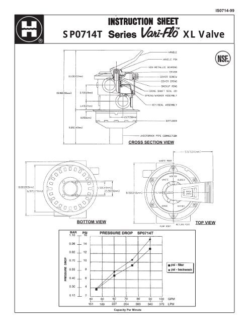
<strong>SP0714T</strong><br />
<strong>XL</strong> <strong>Valve</strong><br />
CROSS SECTION VIEW<br />
BOTTOM VIEW<br />
TOP VIEW<br />
Capacity Per Minute
VALVE SETTING<br />
FILTER<br />
BACKWASH<br />
RINSE<br />
WASTE<br />
CLOSED<br />
RECIRCULATE<br />
WINTER<br />
FUNCTIONS OF VALVE POSITIONS<br />
FLOW DIRECTION THROUGH VALVE<br />
PUMP - TOP - THROUGH FILTER - BOTTOM - RETURN<br />
For normal filtration and vacuuming pool through filter.<br />
PUMP - BOTTOM - THROUGH FILTER - TOP - WASTE<br />
For reversing flow for cleaning filter.<br />
PUMP - TOP - THROUGH FILTER - BOTTOM - WASTE<br />
For initial start-up cleaning, plus resetting filter bed after backwashing.<br />
PUMP - WASTE<br />
For vacuuming directly to waste, lowering pool level/draining pool.<br />
NO CIRCULATION PAST PUMP PORT<br />
For shutting off all flow to filter and pool.<br />
PUMP - RETURN<br />
For bypassing filter, but circulating pool water. May be plumbed for “off-system” pool<br />
water access. Ideal for Jet-Air ® fittings.<br />
VALVE NOT IN USE.<br />
GENERAL<br />
1.<br />
2.<br />
OPTIONAL: A pipe tap boss is provided for use of a pressure gauge.<br />
PLUMBING: Piping stops are provided. IMPORTANT: Do not overtighten pipe fittings. Proper fitting make-up is hand tight<br />
plus one to 1-1/2 turns maximum. Always use Teflon pipe tape or Permatex No. 2 for connections to provide a good, “living”<br />
seal. Add extra sealant if male pipe fitting is undersized.<br />
3. WINTERIZING: Drain and winterize filter and pump per manufacturer’s instructions. To drain water from <strong>Vari</strong>-Flo—depress and<br />
rotate valve handle and place handle pointer on raised portion of index hubs at any “Winter” position.<br />
4. SERVICING VALVE: If it becomes necessary to service or gain access to the key or valve seat gasket:<br />
a. Set handle in Winter position.<br />
b. Remove cover screws.<br />
c. Lift cover and key assembly out.<br />
5. RE-ASSEMBLY VALVE:<br />
a. Wipe debris from cover O-ring.<br />
b. Set handle in Winter position. Align notch on cover with tab on body. Press down to seat assembly.<br />
c. Secure assembly to body with cover screws. Start screw thread in existing thread in body. Tighten cover screws evenly<br />
and alternately. Do not overtighten.<br />
SPECIAL INSTRUCTIONS:<br />
1. Disassembly of key and handle assembly:<br />
a. To remove handle pin: Depress handle to allow pin to clear indexing hub, and tap out handle pin with a drift pin or other<br />
solid pin bar.<br />
b. Remove cover screws and remove parts. Note the proper position and sequence of all parts.<br />
2.<br />
Re-assembly:<br />
a. Place valve key on a smooth, firm surface (place a cloth underneath to protect the flat sealing surface).<br />
b. Place parts on key and shaft in proper sequence—i.e., spring washer, spring, spring washer, cover, bearing, etc. Note:<br />
Make sure “Filter” position on cover is over “wedge” opening in key.<br />
c. Firmly pressing down and holding cover to depress heavy-duty spring, align handle (with pointer to Filter) and secure<br />
handle with pin.<br />
d. Assemble key assembly to valve as in (5)a ,b, and c above.<br />
Rev. 2/99 A<br />
© 1999 <strong>Hayward</strong> Printed in U.S.A.