Lecture 3 Magnetic Circuits
Lecture 3 Magnetic Circuits
Lecture 3 Magnetic Circuits

Create successful ePaper yourself
Turn your PDF publications into a flip-book with our unique Google optimized e-Paper software.
<strong>Lecture</strong> 3<br />
<strong>Magnetic</strong> <strong>Circuits</strong><br />
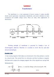
Electromagnetic fields play an important role in the conversion of electromechanical<br />
energy in the rotating machines and transformers. In this lecture some basic concepts<br />
of electromagnetic theory are reviewed, typical magnetic circuits are analyzed and<br />
other parameter, including flux linkages and inductances, are defined.<br />
Production of <strong>Magnetic</strong> Field<br />
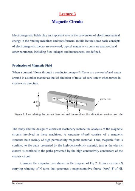
When a current i flows through a conductor, magnetic fluxes are generated and wraps<br />
around in a similar manner as that of direction of travel of cork-screw when turned in<br />
clock-wise direction.<br />
The study and the design of electrical machinery include the analysis of the magnetic<br />
circuits involved in these machines. A magnetic circuit consists of a magnetic<br />
structure built mainly of high permeability magnetic material. Thus, magnetic flux is<br />
confined to the paths presented by the high-permeability material, just as the electric<br />
current is confined to the paths presented by the high-conductivity conductors of the<br />
electric circuit.<br />
Consider the magnetic core shown in the diagram of Fig 2. It has a current (I)<br />
carrying winding of N turns that generates a magnetomotive fource (mmf) F of NI.<br />
Dr. Ahsan Page 1
This mmf creates a magnetic field in the core having an intensity of H c ampereturn/meter<br />
along the length of the magnetic path. According to Ampere’s law<br />
∮ (1)<br />
If H c is constant, and l c is the mean path length of the core, then (1) gives,<br />
H c l c =NI=F= mmf (2)<br />
The core is usually made of ferromagnetic material. The magnetic flux density B<br />
(weber/m 2 ) in the core is related to the magnetic field H according to the saturation<br />
curve, or B-H curve (Fig 3). The slope of this is designated as µ, the permeability of<br />
the material, thus giving relationship between B and H as<br />
B = µH (3)<br />
As seen from Fig 3, the slope of the curve that µ is not constant and depends of the<br />
operating value of magnetic flux density ( ). The permeability of a magnetic material<br />
is usually given relative to the permeability of the free-space, µ 0 . Thus<br />
µ= µ 0 µ r . (4)<br />
where, µ r is the relative permeability. In SI units, the permeability of the free-space is<br />
µ 0 = 410 -7 H/m.<br />
Dr. Ahsan Page 2
Fig 3: Typical B-H curves of different materials.<br />
The magnetic flux (expressed in webers) through a given surface is found as<br />
follows:<br />
∫ (5)<br />
Since the flux density in the core B c has the same direction as<br />
the cross-sectional area, A c , Equation (5) reduces to<br />
and is uniform over<br />
F NI Hclc<br />
NI <br />
Bc Ac Hc Ac Ac<br />
NI<br />
l<br />
H<br />
c <br />
<br />
c<br />
<br />
l<br />
l <br />
<br />
<br />
Ac<br />
<br />
F <br />
c<br />
NI <br />
c<br />
(6)<br />
lc<br />
= reluctance of the magnetic circuit in AT/wb. Eq (6) is analogous to Ohm’s<br />
A<br />
c<br />
law for resistive circuits.<br />
Dr. Ahsan Page 3
Table : Analogy between <strong>Magnetic</strong> and Electric circuits<br />
Electric circuit<br />
<strong>Magnetic</strong> circuit<br />
I=current (A)<br />
= flux (wb)<br />
V= emf (V)<br />
F = mmf (AT)<br />
R= resistance ()<br />
R = reluctance (AT/wb)<br />
= conductivity (S/m) µ = permeability (H/m)<br />
Self study: Example 4.1, 4.2, 4.4<br />
<strong>Magnetic</strong> Circuit with Air-gap and Flux Fringing<br />
At an air-gap in a magnetic core, the flux fringes out into neighboring air paths as<br />
shown in Figure. The result is non-uniform flux density in the air-gap (decreasing<br />
outward), enlargement of the effective air-gap area and a decrease in the average gap<br />
flux density. The fringing effect also disturbs the core flux pattern to some depth near<br />
the gap. The effect of fringing increases with the air-gap length.<br />
Fig: Flux fringing at the air-gap<br />
Dr. Ahsan Page 4
If fringing is neglected, then A g =A c ; B g =B c , g = c ,<br />
but still H g H c and also R g R c due to change in permeability in core and air-gap.<br />
Series Parallel <strong>Magnetic</strong> <strong>Circuits</strong><br />
Dr. Ahsan Page 5
Similar to Kirchhoff’s voltage law, we may write, for any closed path in a magnetic<br />
circuit,<br />
Around a closed path in a magnetic circuit the algebraic sum of ampere-turns is equal<br />
to the algebraic sum of the products of the reluctances and fluxes.<br />
Again, similar to Kirchhoff’s current law for a junction, for any closed path in a<br />
magnetic circuit,<br />
Which states that the algebraic sum of all the magnetic fluxes flowing out of a<br />
junction in a magnetic circuit is zero.<br />
Problems<br />
D4.1 The magnetic circuit shown in Fig. below has an air gap cut in the right leg of<br />
the core. The air gap is 0.1mm long. The coil is connected to a voltage source, and the<br />
current drawn is adjusted so that the magnetic flux density in the air gap is 1.5T.<br />
Assume that flux fringing in the air gap is negligible. The magnetic circuit has the<br />
following dimensions: A c =16cm 2 , l c =40cm, and N=350 turns. The relative<br />
permeability of the core is µ r =50,000.<br />
(i)<br />
(ii)<br />
(iii)<br />
Find the value of the current.<br />
Calculate the magnetic flux<br />
Determine the flux linkage of the coil<br />
Dr. Ahsan Page 6
Solution:<br />
Here, l c = 40cm=0.4m; A c =16cm 2 = m 2 , B g =B c = 1.5T<br />
Reluctance of the core,<br />
Reluctance of the air gap,<br />
Total Reluctance, R t =R c +R g = 3,979+49,736=53,715 AT/wb<br />
(i) Flux, =BA=1.5 =2.4 mWb<br />
(ii)<br />
(iii)<br />
Current<br />
Flux, <br />
(iv) Flux linkage, =N =350 =0.84 wb-t<br />
Problem 4.2 is similar to D4.1.<br />
Dr. Ahsan Page 7
D4.2 A magnetic core is built in the form of a circular ring having a mean radius of 10<br />
cm. A coil containing 150 turns is wound uniformly throughout the length of the core.<br />
The coil is connected to a voltage source, and it draws a current of 15A.<br />
a. Determine the of the coil<br />
b. Calculate the magnetic field intensity in the core<br />
Solution:<br />
Given, N=150 turns; I =15A; r = 10cm = 0.1m<br />
a. <br />
b. l c = 2r = 20.1=0.628 m<br />
c.<br />
D4.3 The circular ring of has a mean cross-sectional area of<br />
25cm 2 . The relative permeability of the material of the ring is 1500. Calculate<br />
a. The magnetic flux in the core<br />
b. The magnetic flux density in the core<br />
c. The flux linkage of the coil<br />
d. The reluctance of the core<br />
Solution:<br />
Here, A c = 25cm 2 =2510 -4 m 2 ; µ r =1500<br />
a. B=µH =µ 0 µ r H =410 -7 15003581=6.75 T<br />
b. =BA=6.752510 -4 wb=16.875 mwb<br />
c. =N=150 =2.53 wb-t<br />
d.<br />
Dr. Ahsan Page 8
D4.4 A magnetic core has a circular cross-sectional area of 2.0 inch 2 , a mean path<br />
length of 10 inch, and an air-gap length of 0.125 inch. A 350-turn coil is wound<br />
around the magnetic core, and a current of 5A is supplied to the coil. Assume that the<br />
relative permeability of the core is and fringing of the flux in the air gap is<br />
negligible.<br />
a. Calculate the reluctance of the magnetic circuit<br />
b. Find the magnetic flux density in the air gap<br />
Solution:<br />
A = 2.0 inch 2 = ( )<br />
g = 0.125 inch =<br />
N = 350 turn; I = 5A<br />
a.<br />
b. =1.96<br />
c.<br />
D4.5 Repeat assuming that the core has a relative permeability<br />
µ r =5000.<br />
Solution:<br />
a. µ r =5000<br />
AT/wb<br />
Dr. Ahsan Page 9
. =1.96 AT/wb<br />
c. Total Reluctance, R t =R c +R g = +1.96 =1.99 AT/wb<br />
Flux,<br />
=0.68 T<br />
Dr. Ahsan Page 10