A Wireless Sensor and Actuator Network for Improving the Electrical ...
A Wireless Sensor and Actuator Network for Improving the Electrical ...
A Wireless Sensor and Actuator Network for Improving the Electrical ...

Create successful ePaper yourself
Turn your PDF publications into a flip-book with our unique Google optimized e-Paper software.
A <strong>Wireless</strong> <strong>Sensor</strong> <strong>and</strong> <strong>Actuator</strong> <strong>Network</strong> <strong>for</strong><br />
<strong>Improving</strong> <strong>the</strong> <strong>Electrical</strong> Power Grid Dependability<br />
António Grilo,<br />
Augusto Casaca,<br />
Paulo Pereira<br />
INESC-ID/IST, Portugal<br />
{antonio.grilo,<br />
augusto.casaca,<br />
paulo.pereira}@inesc-id.pt<br />
Levente Buttyan<br />
BME-HIT, Hungary<br />
buttyan@hit.bme.hu<br />
José Gonçalves<br />
INOV, Portugal<br />
jose.goncalves@inov.pt<br />
Carlos Fortunato<br />
EDP Distribuição, Portugal<br />
carlos.<strong>for</strong>tunato@edp.pt<br />
Abstract— This paper presents an overview of a <strong>Wireless</strong><br />
<strong>Sensor</strong> <strong>and</strong> <strong>Actuator</strong> <strong>Network</strong> (WSAN) used to monitor an<br />
electrical power grid distribution infrastructure. The WSAN<br />
employs appropriate sensors to monitor key grid components,<br />
integrating both safety <strong>and</strong> security services, which improve<br />
<strong>the</strong> grid distribution dependability. The supported applications<br />
include, among o<strong>the</strong>rs, video surveillance of remote secondary<br />
substations, which imposes special requirements from <strong>the</strong> point<br />
of view of quality of service <strong>and</strong> reliability. The paper presents<br />
<strong>the</strong> hardware <strong>and</strong> software architecture of <strong>the</strong> system toge<strong>the</strong>r<br />
with per<strong>for</strong>mance results.<br />
II.<br />
WSAN APPLICATIONS FOR THE POWER GRID<br />
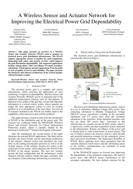
The electrical power grid distribution infrastructure is<br />
schematically shown in Figure 1.<br />
Keywords-<strong>Wireless</strong> <strong>Sensor</strong> <strong>and</strong> <strong>Actuator</strong> <strong>Network</strong>, Power<br />
Grid Distribution Infrastructure, IEEE 802.11, DTSN, RPL.<br />
I. INTRODUCTION<br />
The electrical power grid is a complex <strong>and</strong> critical<br />
infrastructure, which welcomes <strong>the</strong> deployment of extra<br />
technology to improve its dependability. <strong>Wireless</strong> <strong>Sensor</strong> <strong>and</strong><br />
<strong>Actuator</strong> <strong>Network</strong>s (WSAN) can be an important part of <strong>the</strong><br />
additional technological solutions used <strong>for</strong> that purpose. If<br />
deployed in key points of <strong>the</strong> grid <strong>the</strong>y can provide important<br />
in<strong>for</strong>mation to a central control system, whose operator can<br />
trigger <strong>the</strong> most appropriate actions to solve an existing<br />
problem or to avoid problems in <strong>the</strong> near future. An extra set<br />
of actuators included in <strong>the</strong> WSAN can fur<strong>the</strong>r improve <strong>the</strong><br />
capabilities of <strong>the</strong> network to deal with <strong>the</strong> problems.<br />
This paper presents research results from <strong>the</strong> introduction<br />
of WSAN in <strong>the</strong> distribution part of <strong>the</strong> power grid. The<br />
research was conducted within <strong>the</strong> WSAN4CIP (<strong>Wireless</strong><br />
<strong>Sensor</strong> <strong>and</strong> <strong>Actuator</strong> <strong>Network</strong>s <strong>for</strong> Critical Infrastructure<br />
Protection) project, which is partially funded by <strong>the</strong><br />
European Commission 7 th Framework Program of Research.<br />
After <strong>the</strong> introduction, <strong>the</strong> second section of <strong>the</strong> paper<br />
illustrates <strong>the</strong> selected WSAN applications. The third section<br />
describes <strong>the</strong> sensor boards <strong>and</strong> <strong>the</strong> networking architecture<br />
of <strong>the</strong> solution, whereas section four introduces <strong>the</strong> work<br />
done on <strong>the</strong> routing <strong>and</strong> transport protocols as well as in <strong>the</strong><br />
security aspects of <strong>the</strong> solution. Section five refers to <strong>the</strong><br />
central part of <strong>the</strong> system, which interfaces <strong>the</strong> WSAN to <strong>the</strong><br />
SCADA of <strong>the</strong> energy operator. The next two sections<br />
present <strong>the</strong> trial configuration <strong>and</strong> <strong>the</strong> per<strong>for</strong>mance results<br />
obtained with this solution. Finally <strong>the</strong> paper concludes with<br />
an evaluation of <strong>the</strong> technology <strong>and</strong> drawing of conclusions.<br />
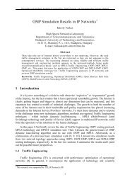
Figure 1. Power grid distribution infrastructure<br />
The power grid distribution infrastructure mainly consists<br />
of a set of substations, Medium Voltage (MV) power lines<br />
connecting substations to Medium Voltage/Low Voltage<br />
(MV/LV) power trans<strong>for</strong>mers residing in <strong>the</strong> secondary<br />
substations <strong>and</strong> LV power lines from <strong>the</strong> secondary<br />
substations to <strong>the</strong> customers. Some industrial customers may<br />
also get direct MV power lines. Associated to this<br />
infrastructure we consider also <strong>the</strong> SCADA system, which is<br />
a supervisory control <strong>and</strong> data acquisition system dedicated<br />
to <strong>the</strong> infrastructure. Remote surveillance of <strong>the</strong> power grid<br />
is already done to some extent based on wired sensors. The<br />
use of wireless sensors can, however, lead to a more flexible<br />
<strong>and</strong> powerful protection scenario <strong>for</strong> <strong>the</strong> substations, power<br />
lines <strong>and</strong> power trans<strong>for</strong>mers. The deployment flexibility of<br />
WSAN allows capturing more status parameters than <strong>the</strong><br />
currently deployed wired sensors <strong>and</strong> <strong>the</strong> self-healing nature<br />
of <strong>the</strong> wireless communication can contribute to avoid<br />
critical points of failure.<br />
In <strong>the</strong> WSAN4CIP project we focused into improving<br />
<strong>the</strong> dependability of <strong>the</strong> substation components, MV <strong>and</strong> LV<br />
power lines, <strong>and</strong> MV/LV power trans<strong>for</strong>mers in <strong>the</strong><br />
secondary substations. We have defined solutions <strong>for</strong> <strong>the</strong>
emote active monitoring of: i) substation circuit breaker trip<br />
coil status; ii) temperature of <strong>the</strong> substation power<br />
trans<strong>for</strong>mer oil, substation neutral reactance oil <strong>and</strong><br />
substation neutral resistor coil box; iii) MV <strong>and</strong> LV power<br />
line current activity; iv) MV/LV power trans<strong>for</strong>mer hotspot<br />
detection; v) human activity in <strong>the</strong> secondary substation<br />
through <strong>the</strong> use of movement detectors <strong>and</strong> video cameras.<br />
All <strong>the</strong> monitored parameters <strong>and</strong> images are visualized at<br />
<strong>the</strong> SCADA system, through a special-purpose graphical<br />
user interface.<br />
In <strong>the</strong> circuit breaker trip coil scenario we consider a<br />
sensor <strong>and</strong> actuator <strong>for</strong> periodically evaluating <strong>the</strong> operating<br />
status of <strong>the</strong> circuit breaker trip coil element. The trip coil<br />
activates <strong>the</strong> circuit breaker when a 110V DC voltage is<br />
applied at its terminals, cutting <strong>the</strong> energy supply to <strong>the</strong><br />
power line. It happens that after activating <strong>the</strong> circuit<br />
breaker <strong>the</strong>re is a chance that <strong>the</strong> coil may be damaged <strong>and</strong><br />
<strong>the</strong> circuit breaker will not function properly in <strong>the</strong> next<br />
event. This solution aims to check <strong>the</strong> working status of <strong>the</strong><br />
trip coil in a pro-active way. A 5V DC voltage will be<br />
applied every 60 minute by an actuator. The magnetic field<br />
generated by <strong>the</strong> coil will be measured by a Hall-effect<br />
transistor. In <strong>the</strong> event of failure, meaning that no magnetic<br />
field is detected when a 5V DC voltage is applied, <strong>the</strong><br />
sensor will report <strong>the</strong> failure back to <strong>the</strong> network. This<br />
solution also allows <strong>for</strong> on dem<strong>and</strong> testing.<br />
The temperature sensor probes to measure <strong>the</strong><br />
temperature in <strong>the</strong> substation trans<strong>for</strong>mers, neutral<br />
reactances <strong>and</strong> neutral resistor coil boxes are placed on <strong>the</strong><br />
external side of <strong>the</strong> metallic oil tank, firmly <strong>and</strong> <strong>the</strong>rmally<br />
attached to <strong>the</strong> tank external wall. The sensor probes are<br />
insulated from <strong>the</strong> external environment with <strong>the</strong>rmal foam.<br />
On normal status a measure will be taken every minute. The<br />
temperature sensor also allows <strong>for</strong> on dem<strong>and</strong> temperature<br />
reading.<br />
The MV power line scenario aims to monitor <strong>the</strong> status<br />
of an MV power line section. It is <strong>the</strong>re<strong>for</strong>e possible to<br />
know centrally <strong>the</strong> location of a power line failure. The<br />
power line chosen is a medium voltage 15kV line that feeds<br />
a set of MV/LV power trans<strong>for</strong>mers in secondary<br />
substations. The line topology is a tree shape with several<br />
leaves, <strong>the</strong> leaves being <strong>the</strong> secondary substations (see<br />
Figure 1). The physical measurement to be done is <strong>the</strong><br />
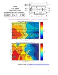
electrical current flowing through <strong>the</strong> line; a current<br />
trans<strong>for</strong>mer is used to measure its value <strong>and</strong> to derive a<br />
parasitic power source <strong>for</strong> <strong>the</strong> wireless sensor, reducing <strong>the</strong><br />
power constrains on <strong>the</strong> wireless protocols through this<br />
energy harvesting technique (Figure 2, bottom-right). The<br />
current sensor samples <strong>the</strong> current on <strong>the</strong> line every second.<br />
We use <strong>the</strong> multi-hop wireless communications link<br />
built in <strong>the</strong> previous scenario to upload a video image feed<br />
of <strong>the</strong> secondary substation to <strong>the</strong> network when movement<br />
is detected. At <strong>the</strong> same time an infrared <strong>the</strong>rmo sensor<br />
attached to <strong>the</strong> camera will sweep <strong>the</strong> power trans<strong>for</strong>mer<br />
critical elements, like <strong>the</strong> main switch board, <strong>for</strong> hotspots<br />
(Figure 2, bottom left). The detection of a hotspot will<br />
trigger an alarm into <strong>the</strong> network. This scenario also<br />
includes an actuator, which turns on <strong>the</strong> lights in <strong>the</strong><br />
secondary substation. Thus, albeit <strong>the</strong> camera shall be night<br />
<strong>and</strong> day capable, <strong>the</strong> user can get a better <strong>and</strong> color video<br />
stream even at night.<br />
The requirement <strong>for</strong> video transmission <strong>and</strong> <strong>the</strong> long<br />
distances between MV power line towers place additional<br />
requirements in terms of <strong>the</strong> communications <strong>and</strong><br />
processing capabilities of <strong>the</strong> WSAN nodes. We have<br />
defined two sensor mote architectures with different<br />
processing power, which can be used in all <strong>the</strong>se<br />
applications <strong>and</strong> that can run a st<strong>and</strong>ard operating system<br />
like Linux. Communication interfaces capable of connecting<br />
to powerful communication networks like Wi-Fi are also<br />
part of <strong>the</strong> mote architecture.<br />
The energy supply to <strong>the</strong> WSAN nodes is obtained from<br />
power supplies in <strong>the</strong> substation <strong>and</strong> secondary substation<br />
installation <strong>and</strong> also from <strong>the</strong> power lines, although in <strong>the</strong><br />
latter case <strong>the</strong> voltages are too high to be used directly by<br />
<strong>the</strong> WSAN nodes, which requires <strong>the</strong> use of intelligent<br />
energy harvesting techniques.<br />
III.<br />
WIRELESS SENSOR BOARDS AND SOFTWARE OF THE<br />
SOLUTION<br />
This section presents an overview of <strong>the</strong> wireless sensor<br />
boards <strong>and</strong> <strong>the</strong> software of <strong>the</strong> solution.<br />
A. <strong>Wireless</strong> <strong>Sensor</strong> Boards<br />
Regarding wireless sensor board hardware, <strong>the</strong> project<br />
WSAN4CIP has integrated two solutions: one based on a<br />
Silex SX-560 core 1 <strong>and</strong> a second solution based on a Beagle<br />
Board 2 . While video compression at <strong>the</strong> secondary substation<br />
requires a more powerful processing node such as <strong>the</strong> Beagle,<br />
scalar sensor nodes can be based on a less powerful board<br />
such as <strong>the</strong> Silex SX-560. The Beagle board is also able to<br />
support a secure operating system. The inclusion of two<br />
different solutions allows also <strong>the</strong> demonstration of a<br />
heterogeneous scenario.<br />
For <strong>the</strong> Silex SX-560 solution <strong>the</strong> PCB designed at INOV<br />
(Figure 2, top) includes a common voltage converter able to<br />
generate 3.3 V DC to feed <strong>the</strong> Silex <strong>and</strong> 5 V DC to feed <strong>the</strong><br />
USB interface (considered a part of <strong>the</strong> <strong>Sensor</strong> Interface<br />
Unit) based on an input of 6-20 V DC. The differences<br />
between <strong>the</strong> WSAN nodes concern <strong>the</strong> Energy Unit <strong>and</strong><br />
<strong>Sensor</strong> Interface Unit, which depend on <strong>the</strong> deployment spot<br />
<strong>and</strong> attached sensor, respectively. The Energy Units are able<br />
to convert from <strong>the</strong> external power source (ei<strong>the</strong>r MV powerline<br />
energy harvesting or 230 V AC mains, depending on <strong>the</strong><br />
scenario) to <strong>the</strong> 6-20 V DC input. Similarly, a 230 V AC to 5<br />
V DC adapter was used <strong>for</strong> <strong>the</strong> Beagle nodes.<br />
The used WSAN radio technology was IEEE 802.11g.<br />
The choice was based on <strong>the</strong> longer communications range<br />
<strong>and</strong> higher data rates required <strong>for</strong> multi-hop video<br />
transmission from <strong>the</strong> secondary substation. Although <strong>the</strong><br />
consumption of IEEE 802.11g is higher than <strong>for</strong> low power<br />
radio technologies such as IEEE 802.15.4, <strong>the</strong> specific<br />
1 http://www.silexeurope.com/en/home/products/wireless-modules/<br />
sx-560.html<br />
2 http://beagleboard.org/
characteristics of <strong>the</strong> target application allow <strong>the</strong> WSAN<br />
nodes at <strong>the</strong> primary <strong>and</strong> secondary substations to be fed<br />
from <strong>the</strong> 230 V AC mains (see above), while <strong>the</strong> MV powerline<br />
sensors may resort to energy harvesting from <strong>the</strong> MV<br />
line current.<br />
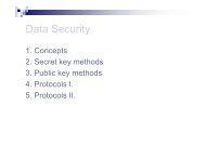
• Management In<strong>for</strong>mation Base (MIB):<br />
Configuration parameters of <strong>the</strong> WSAN nodes.<br />
• Secure Microkernel: trusted software underlying<br />
<strong>the</strong> operating system, which controls access to<br />
all resources of <strong>the</strong> WSAN node.<br />
Figure 3. Software architecture of WSAN node.<br />
Figure 2. Top: Silex sensor with PCB; Bottom-left: <strong>Sensor</strong> with webcam,<br />
infrared camera, LED light <strong>and</strong> movement sensor; Bottom-right: <strong>Sensor</strong><br />
hanging on a 15 KV line, harvesting energy from <strong>the</strong> line.<br />
B. Software<br />
The software modules of <strong>the</strong> WSAN node are depicted in<br />
Figure 3. The selected Operating System is Linux, which is<br />
supported by <strong>the</strong> Silex SX-560 module. In <strong>the</strong> Beagle<br />
solution, Linux runs on top of a secure microkernel [1] that<br />
controls <strong>the</strong> access to all critical resources of <strong>the</strong> WSAN<br />
node.<br />
The main software modules of <strong>the</strong> WSAN node are <strong>the</strong><br />
following:<br />
• WSAN <strong>Sensor</strong>/<strong>Actuator</strong> Application Logic:<br />
Application logic of <strong>the</strong> WSAN node,<br />
managing sensors, actuators <strong>and</strong><br />
communications.<br />
• Dependable Protocol Stack: The dependable<br />
routing <strong>and</strong> transport protocols running over a<br />
st<strong>and</strong>ard IP stack. The transport layer consists<br />
of a secured version of <strong>the</strong> Distributed<br />
Transport <strong>for</strong> <strong>Sensor</strong> <strong>Network</strong>s (DTSN), while<br />
routing consists of a secure version of <strong>the</strong><br />
Routing Protocol <strong>for</strong> Low power <strong>and</strong> Lossy<br />
<strong>Network</strong>s (RPL).<br />
• <strong>Sensor</strong>/<strong>Actuator</strong> Device Driver: Software that<br />
provides access to each type of sensor/actuator.<br />
IV.<br />
ROUTING PROTOCOL, TRANSPORT PROTOCOL AND<br />
PROTOCOL SECURITY<br />
The routing <strong>and</strong> transport protocols, which constitute <strong>the</strong><br />
Dependable Protocol Stack, are especially important to<br />
increase <strong>the</strong> dependability of <strong>the</strong> solution. Although <strong>the</strong> RPL<br />
<strong>and</strong> DTSN protocols already existed, new security extensions<br />
were added <strong>for</strong> use in <strong>the</strong> WSAN4CIP Power Grid, which<br />
significantly contributed to enhance <strong>the</strong> reliability of <strong>the</strong><br />
protocol stack.<br />
A. Secure RPL<br />
In <strong>the</strong> WSAN4CIP solution, we adopted RPL as <strong>the</strong><br />
routing protocol, which is developed by <strong>the</strong> ROLL Working<br />
Group of <strong>the</strong> IETF. The RPL specification is currently in<br />
draft status [2], however, it is expected to become an RFC<br />
soon. RPL is a distance vector routing protocol optimized <strong>for</strong><br />
multipoint-to-point <strong>and</strong> point-to-multipoint communications<br />
within constrained networks. Neighboring nodes in <strong>the</strong><br />
network exchange routing control in<strong>for</strong>mation with each<br />
o<strong>the</strong>r, <strong>and</strong> each node selects a set of, so called, parent nodes.<br />
The resulting parent-child relationships are represented by a<br />
Destination Oriented Directed Acyclic Graph (DODAG)<br />
rooted at <strong>the</strong> sink (or <strong>the</strong> gateway to some wired backbone).<br />
Each node <strong>the</strong>n selects a preferred parent, where <strong>the</strong><br />
selection is guided by <strong>the</strong> objective function in use.<br />
Objective functions are not defined in <strong>the</strong> main RPL<br />
specification, but in separate documents (see e.g., [3]), <strong>and</strong><br />
<strong>the</strong>y can take into account hop count, node rank, link quality,<br />
<strong>and</strong> battery status in<strong>for</strong>mation. Once <strong>the</strong> routing topology is<br />
established, upward (from <strong>the</strong> sensors to <strong>the</strong> sink) <strong>and</strong>
downward (from <strong>the</strong> sink to <strong>the</strong> sensors) routes are selected<br />
along <strong>the</strong> edges of <strong>the</strong> DODAG.<br />
A DODAG is advertised in DODAG In<strong>for</strong>mation Object<br />
(DIO) messages. Among o<strong>the</strong>r things, DIO messages contain<br />
a DODAG version number <strong>and</strong> a node rank value. The<br />
version number is used to determine <strong>the</strong> freshness of <strong>the</strong><br />
routing in<strong>for</strong>mation, while <strong>the</strong> node rank value represents <strong>the</strong><br />
distance of <strong>the</strong> sending node from <strong>the</strong> DODAG root.<br />
Normally, <strong>the</strong> version number is increased by <strong>the</strong> DODAG<br />
root when it wants to initiate <strong>the</strong> re-generation of <strong>the</strong> routing<br />
topology, <strong>and</strong> it remains unchanged in <strong>the</strong> DIO messages<br />
sent by <strong>the</strong> DODAG nodes. In contrast to this, <strong>the</strong> rank value<br />
is updated by each DODAG node to correctly represent <strong>the</strong><br />
node’s distance from <strong>the</strong> root.<br />
There exists an RPL security framework [4], however,<br />
<strong>the</strong> security services of that framework are supposed to<br />
provide protection only against an external attacker. In<br />
particular, <strong>the</strong> current RPL security framework does not<br />
prevent <strong>the</strong> DODAG nodes from manipulating <strong>the</strong> version<br />
number <strong>and</strong> <strong>the</strong> rank value in DIO messages. Un<strong>for</strong>tunately,<br />
if a misbehaving DODAG node increases <strong>the</strong> version number,<br />
<strong>the</strong>n <strong>the</strong> routing topology is re-calculated <strong>and</strong> <strong>the</strong><br />
misbehaving node becomes <strong>the</strong> DODAG root. This allows<br />
<strong>the</strong> misbehaving node to divert <strong>the</strong> entire data traffic in <strong>the</strong><br />
network towards itself <strong>and</strong> control all communications in <strong>the</strong><br />
network. Ano<strong>the</strong>r problem is that a misbehaving node can<br />
maliciously decrease <strong>the</strong> rank value in DIO messages. By<br />
doing so, <strong>the</strong> misbehaving node may become <strong>the</strong> parent of all<br />
of its neighbors, <strong>and</strong> again divert a large part of <strong>the</strong> data<br />
traffic towards itself. In order to prevent <strong>the</strong> illegitimate<br />
increase of <strong>the</strong> version number <strong>and</strong> <strong>the</strong> illegitimate decrease<br />
of <strong>the</strong> rank value in DIO messages, we propose novel<br />
security extensions to <strong>the</strong> RPL protocol. The detailed<br />
description of those extensions can be found in [5].<br />
B. Secure DTSN<br />
The DTSN protocol [6][7] was intended <strong>for</strong> critical data<br />
transfer requiring end-to-end guaranteed delivery, in <strong>the</strong><br />
fashion of TCP. Differently from <strong>the</strong> latter, <strong>for</strong> sake of<br />
improving energy efficiency in WSANs, DTSN employs a<br />
Selective Repeat Automatic Repeat reQuest (SR-ARQ) using<br />
negative acknowledgments (NACK). Positive<br />
acknowledgment packets (ACK) are also used to prevent <strong>the</strong><br />
situations where <strong>the</strong> complete message or its last packet is<br />
lost (which cannot be detected solely based on NACKs).<br />
Both NACKs <strong>and</strong> ACKs are to be sent by <strong>the</strong> receiver only<br />
upon request by <strong>the</strong> sender (Explicit Acknowledgment<br />
Request – EAR), which can be piggy-backed in data packets<br />
at <strong>the</strong> end of each acknowledgement window (a transmission<br />
window consists of one or more acknowledgement windows).<br />
Intermediate nodes can also retransmit packets from <strong>the</strong>ir<br />
packet caches upon NACK interception, avoiding costlyend-to-end<br />
retransmissions.<br />
In DTSN, a session is a source/destination relationship<br />
univocally identified by <strong>the</strong> tuple , designated <strong>the</strong> session identifier ( ).<br />
The Session Number works like a version number of <strong>the</strong><br />
session. In case <strong>the</strong> receiver detects a change in <strong>the</strong> Session<br />
Number while <strong>the</strong> session is still active, it resets <strong>the</strong> session<br />
state, reporting which packets were missing from <strong>the</strong><br />
previous Session Number, if any. This functionality was used<br />
in WSAN4CIP in order to establish a trade-off between<br />
fragment recovery delay <strong>and</strong> frame quality, with each video<br />
frame being transmitted with a different Session Number.<br />
This functionality is especially useful <strong>for</strong> <strong>the</strong> transmission of<br />
multi-layered video.<br />
As shown in [8], reliable transport protocols are<br />
vulnerable to control packet manipulation attacks. In<br />
particular, a <strong>for</strong>ged or altered ACK packet creates <strong>the</strong> false<br />
impression that data packets have been received by <strong>the</strong><br />
destination while in reality <strong>the</strong>y may have been lost, causing<br />
sender <strong>and</strong> destination to become out-of-sync with respect to<br />
<strong>the</strong> status of <strong>the</strong> session. On <strong>the</strong> o<strong>the</strong>r h<strong>and</strong>, NACK packets<br />
may be used to trigger useless retransmissions, leading to<br />
denial of service or at least to faster draining of <strong>the</strong> WSAN<br />
node batteries. To implement security at <strong>the</strong> lower layers is<br />
also energetically inefficient when not all applications have<br />
security requirements. These factors prompt <strong>the</strong> development<br />
of security mechanisms at <strong>the</strong> transport layer.<br />
Though DTSN basically operates end-to-end,<br />
intermediate node caching can significantly improve its<br />
energy efficiency. This active participation of intermediate<br />
nodes means that <strong>the</strong>y must be able to process <strong>and</strong> in some<br />
cases change <strong>the</strong> contents of DTSN headers, constraining <strong>the</strong><br />
use of security solely between sender <strong>and</strong> receiver. The<br />
DTSN security extension proposed in [9] prevents <strong>the</strong><br />
transport session to become out-of-sync through data, ACK<br />
<strong>and</strong> NACK packet au<strong>the</strong>ntication, using symmetric<br />
cryptography schemes exclusively.<br />
The general idea of <strong>the</strong> security mechanism is <strong>the</strong><br />
following: We assume that <strong>the</strong> source <strong>and</strong> <strong>the</strong> destination<br />
share a secret, which we call <strong>the</strong> session master key, <strong>and</strong> we<br />
denote it by . From this, <strong>the</strong>y both derive an ACK master<br />
key <strong>and</strong> a NACK master key <strong>for</strong> <strong>the</strong> session<br />
as follows:<br />
where<br />
is <strong>the</strong> pseudo-r<strong>and</strong>om function defined in<br />
[10] <strong>and</strong> is <strong>the</strong> DTSN session identifier. The<br />
length of K, , <strong>and</strong> is 128 bits each. Each data<br />
packet is extended with two MAC (Message Au<strong>the</strong>ntication<br />
Code) values computed over <strong>the</strong> packet itself with two<br />
different keys, an ACK key <strong>and</strong> a NACK key, both specific<br />
to <strong>the</strong> data packet <strong>and</strong> known only to <strong>the</strong> source <strong>and</strong> <strong>the</strong><br />
destination. The ACK key<br />
<strong>for</strong> <strong>the</strong><br />
sequence number is<br />
<strong>and</strong> NACK key<br />
-th packet of <strong>the</strong> session (i.e., whose<br />
) are computed as follows:
When <strong>the</strong> destination wants to send an ACK referring to<br />
this data packet, it reveals its ACK key; similarly, when it<br />
wants to signal that this data packet is missing, it reveals its<br />
NACK key. Now, any intermediate node that has <strong>the</strong> data<br />
packet in question can verify if <strong>the</strong> NACK is au<strong>the</strong>ntic by<br />
checking if <strong>the</strong> appropriate MAC verifies correctly with <strong>the</strong><br />
given key. As only <strong>the</strong> source <strong>and</strong> <strong>the</strong> destination can<br />
produce <strong>the</strong> right keys, but <strong>the</strong> source never reveals <strong>the</strong>m, <strong>the</strong><br />
intermediate node can be sure that <strong>the</strong> control in<strong>for</strong>mation<br />
must have been sent by <strong>the</strong> destination. Besides, intermediate<br />
nodes manage <strong>the</strong> cache following a strict FIFO policy <strong>and</strong><br />
thus <strong>the</strong>y never delete cached data packets upon reception of<br />
a NACK or ACK. Regarding end-to-end synchronization, <strong>the</strong><br />
source only deletes data packets from its transmission<br />
window if <strong>the</strong> appropriate MAC matches <strong>the</strong> ACK keys in<br />
control packets. A side effect of <strong>the</strong> scheme is that <strong>the</strong> MAC<br />
values provide end-to-end protection, meaning that <strong>the</strong><br />
destination can check <strong>the</strong> au<strong>the</strong>nticity <strong>and</strong> integrity of each<br />
received data packet, which is also a desirable feature.<br />
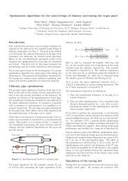
V. GATEWAY BETWEEN THE WSAN AND SCADA<br />
The substation devices are nowadays monitored <strong>and</strong><br />
controlled through <strong>the</strong> Supervisory Control <strong>and</strong> Data<br />
Acquisition (SCADA) system. The WSAN is integrated with<br />
this existing system by means of a SCADA/WSAN Gateway,<br />
in order to provide a unified power distribution infrastructure<br />
interface to <strong>the</strong> human operators (Figure 4).<br />
Figure 4. Integration between WSAN <strong>and</strong> SCADA system.<br />
The SCADA protocol architecture is generic enough to<br />
be operated in an Internet Protocol (IP) environment on top<br />
of different network technologies such as E<strong>the</strong>rnet <strong>and</strong><br />
SONET/SDH. However, <strong>the</strong> WSAN presents a specific<br />
networking environment where <strong>the</strong> energy <strong>and</strong> b<strong>and</strong>width<br />
optimization requirements are often incompatible with <strong>the</strong><br />
request/response philosophy behind SCADA. These<br />
differences lead to <strong>the</strong> need of translating SCADA<br />
procedures to WSAN procedures <strong>and</strong> vice versa, which is <strong>the</strong><br />
purpose of <strong>the</strong> SCADA/WSAN gateway.<br />
The gateway consists of a PC equipped with an E<strong>the</strong>rnet<br />
interface. This E<strong>the</strong>rnet interface interconnects it to <strong>the</strong><br />
SCADA system <strong>and</strong> to <strong>the</strong> WSAN sink node. The latter<br />
consists of a of a Silex SX-560 board. The WSAN sink node<br />
is <strong>the</strong> main destination of sensor data <strong>and</strong> main source of<br />
queries <strong>and</strong> configuration/comm<strong>and</strong> requests.<br />
From <strong>the</strong> point of view of <strong>the</strong> SCADA system, <strong>the</strong><br />
SCADA/WSAN gateway behaves as a database of sensing<br />
<strong>and</strong> management data that responds to its queries about <strong>the</strong><br />
status of WSAN devices. The application interface <strong>for</strong> <strong>the</strong>se<br />
queries is based on Web Services [11], with <strong>the</strong> gateway<br />
implementing <strong>the</strong> server side. On <strong>the</strong> o<strong>the</strong>r h<strong>and</strong>, <strong>the</strong><br />
SCADA system implements <strong>the</strong> server side of Web Services<br />
related with urgent asynchronous notifications such as alarms.<br />
The use of <strong>the</strong> Web Service interface per<strong>for</strong>ms an adequate<br />
mapping of <strong>the</strong> SCADA data access mechanisms, which<br />
follows a client/server paradigm.<br />
The main functions of <strong>the</strong> SCADA/WSAN gateway are:<br />
• To translate between WSAN messages <strong>and</strong> Web<br />
Services <strong>and</strong> vice-versa.<br />
• To keep <strong>the</strong> log of WSAN activity.<br />
• To detect WSAN topology changes <strong>and</strong> initiate<br />
route recovery by means of <strong>the</strong> RPL interface.<br />
VI.<br />
TRIAL DEPLOYMENT<br />
A proof-of-concept demonstrator was deployed at EDP<br />
Distribuição 3 premises, more precisely at <strong>the</strong> São Sebastião<br />
primary substation, located in <strong>the</strong> neighborhood of <strong>the</strong> city<br />
of Setúbal, in <strong>the</strong> west of Portugal. The São Sebastião<br />
substation provides electric energy to <strong>the</strong> Setúbal region.<br />
The EDP demonstrator encompasses <strong>the</strong> sections of <strong>the</strong><br />
electricity distribution infrastructure, similar to <strong>the</strong> depiction<br />
in Figure 1.<br />
The type <strong>and</strong> number of sensors deployed in <strong>the</strong> trial<br />
were as follows:<br />
• Trip-coil SX-560 sensor/actuator nodes : 2<br />
• Neutral Resistance SX-560 temperature sensor nodes: 1<br />
• Neutral Reactance SX-560 temperature sensor nodes: 1<br />
• HV/MV Trans<strong>for</strong>mer SX-560 temperature sensor<br />
nodes: 1<br />
• Neutral Resistance Beagle board temperature sensor<br />
nodes: 1<br />
• Neutral Reactance Beagle board temperature sensor<br />
nodes: 1<br />
• HV/MV Trans<strong>for</strong>mer Beagle board temperature sensor<br />
nodes: 1<br />
• LV current measurement sensor nodes: 5<br />
• MV current measurement sensor nodes: 1<br />
• Secondary substation surveillance <strong>and</strong> hotspot detection<br />
Beagle board sensor node: 1<br />
• Extra SX-560 relay node to bridge <strong>the</strong> distance from <strong>the</strong><br />
power lines to <strong>the</strong> secondary substation: 1<br />
The SCADA system <strong>and</strong> WSAN Gateway were both<br />
deployed at <strong>the</strong> São Sebastião substation – as would be <strong>the</strong><br />
3 EDP Distribuição is <strong>the</strong> main company that carries out <strong>the</strong><br />
function of electricity distribution operator in mainl<strong>and</strong><br />
Portugal.
case in a real system –, though in this case it remained<br />
logically separate from <strong>the</strong> EDP private network <strong>for</strong> security<br />
reasons. External Internet connectivity to <strong>the</strong> SCADA server<br />
was provided in order to allow most of <strong>the</strong> functional <strong>and</strong><br />
per<strong>for</strong>mance tests to be per<strong>for</strong>med by <strong>the</strong> project partners<br />
from <strong>the</strong>ir own premises.<br />
VII. PERFORMANCE RESULTS<br />
Tests were conducted in <strong>the</strong> WSAN4CIP trial network in<br />
order to assess <strong>the</strong> per<strong>for</strong>mance of <strong>the</strong> supported services <strong>and</strong><br />
compliance with <strong>the</strong> requirements provided by EDP<br />
Distribuição. Due to <strong>the</strong> high per<strong>for</strong>mance dem<strong>and</strong> of multihop<br />
video transmission <strong>and</strong> <strong>the</strong> fact that video was<br />
transmitted on top of <strong>the</strong> DTSN transport protocol, <strong>the</strong> video<br />
per<strong>for</strong>mance tests are presented separately from <strong>the</strong> o<strong>the</strong>r<br />
applications.<br />
A. Scalar <strong>Sensor</strong> Tests<br />
For <strong>the</strong> current measurement tests, extra current was<br />
externally injected in <strong>the</strong> LV lines by <strong>the</strong> EDP technicians<br />
<strong>and</strong> <strong>the</strong> sensor reports were confronted against <strong>the</strong> known<br />
current injection values.<br />
For <strong>the</strong> trip-coil, on-dem<strong>and</strong> tests were per<strong>for</strong>med while<br />
<strong>the</strong> trip-coil was operational. Then, <strong>the</strong> 110 V terminal was<br />
disconnected from <strong>the</strong> trip-coil to check whe<strong>the</strong>r <strong>the</strong><br />
malfunction was automatically detected. The on-dem<strong>and</strong> test<br />
was also repeated under this condition.<br />
For <strong>the</strong> intrusion <strong>and</strong> hotspot detection tests, <strong>the</strong><br />
respective situations were simulated by <strong>the</strong> EDP <strong>and</strong> INOV<br />
team. The tests entailed <strong>the</strong> transmission of images from <strong>the</strong><br />
LV/MV power trans<strong>for</strong>mer to <strong>the</strong> primary substation. For <strong>the</strong><br />
hotspot detection, a soldering iron was placed in front of <strong>the</strong><br />
camera, while <strong>for</strong> intrusion detection, a member of <strong>the</strong> EDP<br />
team simulated intrusions in <strong>the</strong> secondary substations.<br />
The measurement precision test results are listed in Table<br />
I <strong>and</strong> Table II. It should be noted that <strong>the</strong>se results already<br />
have sensor calibration into account. Regarding <strong>the</strong><br />
temperature measurements, <strong>the</strong> precision is high, with an<br />
average error of 1% <strong>and</strong> maximum of 3%. For <strong>the</strong> power line<br />
current measurements, <strong>the</strong> average error was 4.58% with<br />
peaks of 10.83%. This precision is enough to detect<br />
breakdown spots in <strong>the</strong> power-lines as well as to provide<br />
coarse reports about <strong>the</strong> distribution of current consumption<br />
within <strong>the</strong> EDP network. The remaining components feature<br />
a high precision.<br />
TABLE I.<br />
Application<br />
TEMPERATURE AND CURRENT PRECISION EVALUATION.<br />
Number<br />
of Trials<br />
Average<br />
Error<br />
Maximum<br />
Error<br />
St<strong>and</strong>ard<br />
Deviation<br />
Power<br />
Trans<strong>for</strong>mer Oil 10 1.0% 3.0% 0.4%<br />
Temperature 4<br />
Power Line<br />
Current<br />
20 4.6% 10.9% 3.1%<br />
4 Temperature precision measurements were similar <strong>for</strong> <strong>the</strong><br />
Neutral Reactance <strong>and</strong> Neutral Resistance components,<br />
since <strong>the</strong> sensor node is <strong>the</strong> same.<br />
Application<br />
TABLE II.<br />
Number of<br />
Trials<br />
EVENT PRECISION EVALUATION.<br />
Measurement<br />
Errors<br />
Success<br />
Rate<br />
Trip Coil 24 0 100%<br />
Intrusion<br />
Detection<br />
Hotspot<br />
Detection<br />
11 0 100 %<br />
10 0 100 %<br />
The delay per<strong>for</strong>mance results are listed in Table III.<br />
Application<br />
TABLE III.<br />
Average<br />
Delay<br />
DELAY EVALUATION.<br />
St<strong>and</strong>ard<br />
Deviation<br />
(%)<br />
Delay Bound<br />
Requirement<br />
On-dem<strong>and</strong> Trip Coil<br />
RTT 5 20.9 ms 3.9 ms < 2 s<br />
Power Trans<strong>for</strong>mer<br />
Oil Temperature RTT<br />
Neutral Reactance Oil<br />
Temperature RTT<br />
Neutral Resistor Coil<br />
Box Temperature<br />
RTT<br />
Power Line Current<br />
Measurement (1 hop)<br />
Power Line Current<br />
Measurement (5<br />
hops)<br />
18.4 ms 4.8 ms < 2 s<br />
21.9 ms 5.4 ms < 2 s<br />
19.9 ms 6.3 ms < 2 s<br />
21.5 ms 5.1 ms < 10 s<br />
120.2 ms 10.0 ms < 10 s<br />
Intrusion Detection 2.1 s 1.1 s < 10 s<br />
Hotspot Detection 2.2 s 0.4 s < 10 s<br />
The power-line sensing delay was measured at two<br />
different nodes, located at 1 hop <strong>and</strong> 5 hops from <strong>the</strong> sink. At<br />
5 hops, <strong>the</strong> delay was still a small fraction of <strong>the</strong> allowed<br />
maximum. Intrusion <strong>and</strong> hotspot detection figures are<br />
relative to <strong>the</strong> sensor node located at <strong>the</strong> secondary<br />
substation, which was positioned at approximately 7 hops<br />
from <strong>the</strong> sink node.<br />
Regarding packet losses, no packets were lost during <strong>the</strong><br />
scalar sensor tests.<br />
B. Video Per<strong>for</strong>mance<br />
The results of <strong>the</strong> video per<strong>for</strong>mance evaluation tests are<br />
listed in Table IV. Results are presented <strong>for</strong> both DTSN <strong>and</strong><br />
UDP, in both cases running over <strong>the</strong> IP protocol. UDP is<br />
currently <strong>the</strong> de facto transport protocol <strong>for</strong> delay-sensitive<br />
multimedia data, although it provides no reliability support.<br />
As can be seen, both UDP <strong>and</strong> DTSN present similar<br />
delay <strong>and</strong> jitter per<strong>for</strong>mance, being able to comply with <strong>the</strong><br />
requirements defined by EDP. DTSN achieves lower frame<br />
losses (0%) due to its error recovery mechanism, while<br />
achieving slightly lower delay. Although nei<strong>the</strong>r of <strong>the</strong> tested<br />
transport protocols is able to provide <strong>the</strong> required channel<br />
capacity of 768 Kbit/s, both are able to support <strong>the</strong> required<br />
resolution at a frame rate that is even higher than <strong>the</strong> one<br />
defined <strong>the</strong>rein. The difference towards <strong>the</strong> required channel<br />
5 Round Trip Time.
capacity is also not too significant, being respectively 11.5%<br />
<strong>and</strong> 12.5% <strong>for</strong> UDP <strong>and</strong> DTSN.<br />
TABLE IV.<br />
TransportProtoc<br />
ol<br />
UDP<br />
DTSN<br />
Paramete<br />
r<br />
VIDEO STREAMING EVALUATION.<br />
Averag<br />
e<br />
St<strong>and</strong>ar<br />
d<br />
Deviatio<br />
n<br />
Requiremen<br />
t<br />
Delay 183 ms 35 ms < 10 s<br />
Jitter 10 ms 4 ms < 200 ms<br />
Throughpu<br />
t<br />
Video<br />
frames lost<br />
Channel<br />
capacity<br />
233<br />
Kbit/s<br />
- -<br />
0.83% 2% < 2%<br />
680<br />
Kbit/s<br />
191<br />
Kbit/s<br />
768 Kbit/s<br />
Delay 176 ms 37 ms < 10 s<br />
Jitter 11 ms 5 ms < 200 ms<br />
Throughpu<br />
t<br />
Video<br />
frames lost<br />
Channel<br />
Capacity<br />
243<br />
Kbit/s<br />
- -<br />
0.00% 0.00% < 2%<br />
672<br />
Kbit/s<br />
188<br />
Kbit/s<br />
768 Kbit/s<br />
DTSN was separately tested with <strong>and</strong> without security<br />
functions enabled. For <strong>the</strong> unsecure configuration, DTSN<br />
was tested in a linear 3-hop topology, with a physical Packet<br />
Error Rate (PER) of 5% being introduced. The DTSN<br />
transmission window configuration was three<br />
acknowledgement windows of eight packets each. The<br />
results are listed in Table V <strong>for</strong> <strong>the</strong> guaranteed delivery<br />
scenario with different packet sizes, attesting <strong>the</strong> significant<br />
impact of intermediate node caching. Since it avoids end-toend<br />
retransmissions, <strong>the</strong> caching mechanism is able to reduce<br />
<strong>the</strong> round-trip-time as well as to minimize <strong>the</strong> overhead,<br />
which leads to a throughput increment. The higher <strong>the</strong> packet<br />
loss rate, <strong>the</strong> higher <strong>the</strong> improvement using transport caching.<br />
TABLE V.<br />
Packet Size<br />
(bytes)<br />
DTSN PERFORMANCE WITH DISABLED SECURITY.<br />
Throughput w/o Cache<br />
(kbit/s)<br />
Throughput w/ Cache<br />
(kbit/s)<br />
200 276.72 311.71<br />
500 546.63 802.01<br />
1000 870.51 1212.12<br />
1300 901.41 1485.61<br />
The impact of security was also evaluated in terms of <strong>the</strong><br />
maximum achievable throughput. Experiments were carried<br />
out with a 7-hop topology where <strong>the</strong> sink node was a PC.<br />
The packet size was 1400 bytes. The results are listed in<br />
Table VI.<br />
The impact of security can clearly be seen, especially<br />
when <strong>the</strong> destination of data is a sensor node. The<br />
per<strong>for</strong>mance increase introduced by caching can partially<br />
compensate <strong>the</strong> inefficiency introduced by <strong>the</strong> security<br />
mechanism, but only when <strong>the</strong> caching mechanism is<br />
effective (i.e., <strong>for</strong> PER greater or equal than 5%), leading to<br />
higher throughput compared with <strong>the</strong> end-to-end solution<br />
even if without security.<br />
Packet<br />
Error<br />
Rate (%)<br />
TABLE VI.<br />
DTSN PERFORMANCE IN A 7-HOP TOPOLOGY.<br />
Throughput (kbit/s)<br />
w/o Cache w/o<br />
Security<br />
w/ Cache w/o<br />
Security<br />
<strong>Sensor</strong> PC <strong>Sensor</strong> PC<br />
→ → → →<br />
PC <strong>Sensor</strong> PC <strong>Sensor</strong><br />
w/Cache<br />
w/ Security<br />
<strong>Sensor</strong><br />
→<br />
PC<br />
PC<br />
→<br />
<strong>Sensor</strong><br />
0 1112 1009 1119 1084 1098 1007<br />
5 782 655 865 952 810 778<br />
10 699 584 719 850 705 703<br />
VIII. TECHNOLOGY EVALUATION<br />
This section presents <strong>the</strong> technology evaluation on <strong>the</strong><br />
deployment of <strong>the</strong> WSAN4CIP solution in <strong>the</strong> EDP<br />
electricity distribution network, taking also a businessoriented<br />
perspective besides <strong>the</strong> technical perspective. These<br />
conclusions are based both on <strong>the</strong> results of <strong>the</strong> WSAN4CIP<br />
trial <strong>and</strong> on data from EDP.<br />
A. Scalability of <strong>the</strong> solution<br />
Taking into account <strong>the</strong> throughput provided by IEEE<br />
802.11g, <strong>the</strong> traffic patterns as well as <strong>the</strong> deployment<br />
constraints of <strong>the</strong> solution, it is clear that <strong>the</strong> main scalability<br />
challenges are related with <strong>the</strong> transmission of video from<br />
<strong>the</strong> secondary substations through <strong>the</strong> MV lines to <strong>the</strong><br />
gateway located at <strong>the</strong> primary substation. In fact, <strong>the</strong><br />
substation traffic generated by <strong>the</strong> sensors is very low <strong>and</strong><br />
has to cross at most 2 hops, <strong>the</strong>re<strong>for</strong>e it is not a scalability<br />
issue. Also <strong>the</strong> current measurements at <strong>the</strong> MV towers,<br />
besides presenting a low data rate, can be additionally<br />
aggregated along <strong>the</strong> subnetwork tree in order to reduce <strong>the</strong><br />
traffic even more, which means that this is also not a<br />
scalability problem.<br />
The number of hops between <strong>the</strong> secondary substation<br />
<strong>and</strong> <strong>the</strong> WSAN Gateway varies greatly in <strong>the</strong> different lines<br />
along <strong>the</strong> country. Normally, <strong>the</strong> lines present a tree topology<br />
in which <strong>the</strong> secondary substations (MV/LV power<br />
trans<strong>for</strong>mers) are located along <strong>the</strong> MV lines. This means<br />
that images transmitted from <strong>the</strong> secondary substations<br />
traverse from a small number of hops to a maximum number,<br />
which can be above 100 hops. Experiments have shown that<br />
<strong>the</strong> data rate of power-line sensor nodes is reduced with <strong>the</strong><br />
increase in <strong>the</strong> number of hops, though <strong>the</strong> reduction is<br />
nonlinear. Simulations have shown that under acceptable link<br />
quality, several video streams can be reliably transmitted at<br />
least up to 70 hops, though in real conditions <strong>the</strong> feasible<br />
number of hops would probably be reduced. For<br />
transmission along a large number of hops, alternative<br />
solutions would have to be implemented. One possibility is<br />
to transmit <strong>the</strong> video to nearby gateways that can dispatch<br />
<strong>the</strong> traffic through a broadb<strong>and</strong> access technology such as<br />
ADSL, HFC, WiMAX, LTE, <strong>for</strong> example.
The integrated intrusion detection solution allows <strong>the</strong><br />
video streaming to be activated only upon detection of <strong>the</strong><br />
intrusion event, which may be triggered by <strong>the</strong> Passive<br />
Infrared (PIR) movement detector. A similar solution was<br />
implemented regarding hotspot detection <strong>and</strong> Infrared (IR)<br />
video streaming, in which activation of <strong>the</strong> video stream is<br />
triggered based on a temperature threshold. Since <strong>the</strong>se<br />
events are rare <strong>and</strong> are very unlikely to occur simultaneously<br />
(at least in significant numbers), <strong>the</strong> selected technology <strong>and</strong><br />
deployment architecture are enough to support <strong>the</strong>se services.<br />
However, a commercial solution would require additional<br />
software functionality that was not implemented in <strong>the</strong><br />
prototype, namely <strong>the</strong> capability to alternate between video<br />
streams, while temporarily switching-off <strong>the</strong> streams that are<br />
not being visualized at <strong>the</strong> moment. This would significantly<br />
increase <strong>the</strong> number of intrusion detection <strong>and</strong> hotspot events<br />
that can be simultaneously monitored.<br />
B. Impact on business<br />
When evaluating <strong>the</strong> advantages of <strong>the</strong> proposed system<br />
on EDP’s business, it must be taken into account that as an<br />
energy distribution company, EDP’s objectives go beyond<br />
getting financial profits. EDP has also an important social<br />
role. Hence, although it was not possible to get precise<br />
figures on <strong>the</strong> financial impact of <strong>the</strong> proposed solution, <strong>the</strong><br />
following advantages can be readily identified:<br />
1. The timely detection of a trip-coil break down will<br />
ensure that <strong>the</strong> repair is done be<strong>for</strong>e <strong>the</strong> protected equipment<br />
(e.g. neutral reactance/resistance <strong>and</strong> ultimately <strong>the</strong> MV/HV<br />
power trans<strong>for</strong>mer) is damaged, preventing long blackouts<br />
that would affect <strong>the</strong> population of Setúbal (<strong>the</strong> nearby city<br />
in this deployment) as well as industrial clients.<br />
2. The timely detection of a neutral<br />
resistance/reactance malfunction will avoid that <strong>the</strong> protected<br />
HV/MV power trans<strong>for</strong>mer is damaged upon <strong>the</strong> occurrence<br />
of a short circuit in <strong>the</strong> MV lines.<br />
3. The quick detection <strong>and</strong> localization of a problem in<br />
some segment of <strong>the</strong> power-lines will speed-up <strong>the</strong> repair,<br />
minimizing <strong>the</strong> time that <strong>the</strong> clients will remain without<br />
energy.<br />
4. The timely detection of a malfunction on <strong>the</strong><br />
MV/LV power trans<strong>for</strong>mers will minimize <strong>the</strong> damage <strong>and</strong><br />
allow a quick repair, minimizing <strong>the</strong> impact on <strong>the</strong> clients.<br />
5. The surveillance of <strong>the</strong> secondary substations will<br />
discourage <strong>the</strong>ft of equipment or v<strong>and</strong>alism activities, which<br />
will also improve <strong>the</strong> service offered to EDP clients.<br />
IX.<br />
CONCLUSION<br />
This paper has presented a WSAN <strong>for</strong> monitoring <strong>and</strong><br />
increasing <strong>the</strong> dependability of a power grid distribution<br />
infrastructure. Requirements of <strong>the</strong> power distribution<br />
infrastructure such as transmission ranges <strong>and</strong> throughput<br />
have led to an IEEE 802.11g solution coupled with energy<br />
harvesting to recharge <strong>the</strong> WSAN node batteries in places<br />
where <strong>the</strong>y cannot be directly fed from <strong>the</strong> power<br />
infrastructure. On <strong>the</strong> o<strong>the</strong>r h<strong>and</strong>, dependability requirements<br />
have led to special reliability <strong>and</strong> security mechanisms being<br />
embedded in <strong>the</strong> transport <strong>and</strong> routing protocols.<br />
A pilot system was deployed <strong>for</strong> a trial in <strong>the</strong> power<br />
distribution grid in <strong>the</strong> region of Setúbal, Portugal.<br />
Per<strong>for</strong>mance results indicate that <strong>the</strong> proposed architecture is<br />
able to meet <strong>the</strong> application requirements.<br />
ACKNOWLEDGMENT<br />
The research leading to <strong>the</strong>se results has received funding<br />
from <strong>the</strong> European Community's Seventh Framework<br />
Programme (FP7/2007-2013) under grant agreement n°<br />
225186 (www.wsan4cip.eu). The authors acknowledge also<br />
<strong>the</strong> funding from FCT - Fundação para a Ciência e a<br />
Tecnologia (INESC-ID multiannual funding) through <strong>the</strong><br />
PIDDAC program.<br />
The in<strong>for</strong>mation in this document is provided 'as is', <strong>and</strong> no<br />
guarantee or warranty is given that <strong>the</strong> in<strong>for</strong>mation is fit <strong>for</strong><br />
any particular purpose. The use of <strong>the</strong> in<strong>for</strong>mation is at <strong>the</strong><br />
sole risk <strong>and</strong> liability of <strong>the</strong> user.<br />
REFERENCES<br />
[1] D. Gessner, M. Selhorst, C. Stüble, P. Langendoerfer, “Realising a<br />
Trustworthy <strong>Sensor</strong> Node with <strong>the</strong> Idea of Virtualization,”<br />
Proceedings of <strong>the</strong> 6th Future Security Conference 2011, Berlin,<br />
Germany, September 2011.<br />
[2] T. Winter, P. Thubert, A. Br<strong>and</strong>t, T. Clausen, J. Hui, R. Kelsey, P.<br />
Levis, K. Pister, R. Struik, <strong>and</strong> J. Vasseur, “RPL: IPv6 Routing<br />
Protocol <strong>for</strong> Low power <strong>and</strong> Lossy <strong>Network</strong>s,” Internet Draft, draftietf-roll-rpl-19,<br />
March 2011.<br />
[3] P. Thubert (ed), “RPL Objective Function 0,” Internet Draft, draftietf-roll-of0-19,<br />
March 2011.<br />
[4] T. Tsao, M. Dohler, V. Daza, <strong>and</strong> A. Lozano, “A security framework<br />
<strong>for</strong> Routing over Low power <strong>and</strong> Lossy <strong>Network</strong>s,” Internet Draft,<br />
draft-ietfroll-security-framework-06, June 2011.<br />
[5] A. Dvir, T. Holczer, L. Dora, L. Buttyan, “Version Number <strong>and</strong> Rank<br />
Au<strong>the</strong>ntication <strong>for</strong> RPL,” Internet Draft, draft-dvir-roll-securityau<strong>the</strong>ntication-00,<br />
July 2011.<br />
[6] B. Marchi, A. Grilo, <strong>and</strong> M. Nunes, "DTSN: Distributed Transport <strong>for</strong><br />
<strong>Sensor</strong> <strong>Network</strong>s," Proceedings of <strong>the</strong> IEEE Symposium on<br />
Computers <strong>and</strong> Communications (ISCC'07), Aveiro, Portugal, IEEE,<br />
ISBN 978-1-4244-1520-5, 1-4 July 2007, pp.165-172.<br />
[7] F. Rocha, A. Grilo, P.R. Pereira, M.S. Nunes, <strong>and</strong> A. Casaca,<br />
"Per<strong>for</strong>mance Evaluation of DTSN in <strong>Wireless</strong> <strong>Sensor</strong> <strong>Network</strong>s,"<br />
Proceedings of <strong>Wireless</strong> Systems <strong>and</strong> Mobility in Next Generation<br />
Internet: 4th International Workshop of <strong>the</strong> EuroNGI/EuroFGI<br />
<strong>Network</strong> of Excellence Barcelona, Spain, January 16-18, 2008<br />
Revised Selected Papers, Springer-Verlag, 2008, pp. 1-9.<br />
[8] L. Buttyan <strong>and</strong> L. Csik, “Security analysis of reliable transport layer<br />
protocols <strong>for</strong> wireless sensor networks,” in Proceedings of <strong>the</strong> IEEE<br />
Workshop on <strong>Sensor</strong> <strong>Network</strong>s <strong>and</strong> Systems <strong>for</strong> Pervasive Computing<br />
(PerSeNS), March 2010.<br />
[9] L. Buttyán, A. Grilo, “A Secure Distributed Transport Protocol <strong>for</strong><br />
<strong>Wireless</strong> <strong>Sensor</strong> <strong>Network</strong>s”, Proceedings of <strong>the</strong> IEEE International<br />
Conference on Communications 2011 (ICC’2011), Kyoto, Japan,<br />
June 2011.<br />
[10] T. Dierks <strong>and</strong> E. Rescorla, “The Transport Layer Security (TLS)<br />
Protocol Version 1.2,” Internet RFC 5246, August 2008.<br />
[11] W3C, Web Services Architecture, W3C Working Group Note 11,<br />
URL:http://www.w3.org/TR/2004/NOTE-ws-arch-20040211/,<br />
February 2004