LTC1666/LTC1667/LTC1668 APPLICATIO S U TYPICAL ...
LTC1666/LTC1667/LTC1668 APPLICATIO S U TYPICAL ...
LTC1666/LTC1667/LTC1668 APPLICATIO S U TYPICAL ...

Create successful ePaper yourself
Turn your PDF publications into a flip-book with our unique Google optimized e-Paper software.
FEATURES<br />
■<br />
■<br />
■<br />
■<br />
■<br />
■<br />
■<br />
■<br />
■<br />
50Msps Update Rate<br />
Pin Compatible 12-Bit, 14-Bit and 16-Bit Devices<br />
High Spectral Purity: 87dB SFDR at 1MHz f OUT<br />
5pV-s Glitch Impulse<br />
Differential Current Outputs<br />
20ns Settling Time<br />
Low Power: 180mW from ±5V Supplies<br />
TTL/CMOS (3.3V or 5V) Inputs<br />
Small Package: 28-Pin SSOP<br />
<strong>APPLICATIO</strong> S<br />
U<br />
■<br />
■<br />
■<br />
■<br />
■<br />
■<br />
■<br />
■<br />
Cellular Base Stations<br />
Multicarrier Base Stations<br />
Wireless Communication<br />
Direct Digital Synthesis (DDS)<br />
xDSL Modems<br />
Arbitrary Waveform Generation<br />
Automated Test Equipment<br />
Instrumentation<br />
<strong>LTC1666</strong>/<strong>LTC1667</strong>/<strong>LTC1668</strong><br />
12-Bit, 14-Bit, 16-Bit,<br />
50Msps DACs<br />
DESCRIPTIO<br />
U<br />
The LTC ® 1666/<strong>LTC1667</strong>/<strong>LTC1668</strong> are 12-/14-/16-bit,<br />
50Msps differential current output DACs implemented on<br />
a high performance BiCMOS process with laser trimmed,<br />
thin-film resistors. The combination of a novel currentsteering<br />
architecture and a high performance process<br />
produces DACs with exceptional AC and DC performance.<br />
The <strong>LTC1668</strong> is the first 16-bit DAC in the marketplace to<br />
exhibit an SFDR (spurious free dynamic range) of 87dB<br />
for an output signal frequency of 1MHz.<br />
Operating from ±5V supplies, the <strong>LTC1666</strong>/<strong>LTC1667</strong>/<br />
<strong>LTC1668</strong> can be configured to provide full-scale output<br />
currents up to 10mA. The differential current outputs of<br />
the DACs allow single-ended or true differential operation.<br />
The –1V to 1V output compliance of the <strong>LTC1666</strong>/<br />
<strong>LTC1667</strong>/<strong>LTC1668</strong> allows the outputs to be connected<br />
directly to external resistors to produce a differential output<br />
voltage without degrading the converter’s linearity. Alternatively,<br />
the outputs can be connected to the summing<br />
junction of a high speed operational amplifier, or to a<br />
transformer.<br />
The <strong>LTC1666</strong>/<strong>LTC1667</strong>/<strong>LTC1668</strong> are pin compatible and<br />
are available in a 28-pin SSOP and are fully specified over<br />
the industrial temperature range.<br />
, LTC and LT are registered trademarks of Linear Technology Corporation.<br />
<strong>TYPICAL</strong> <strong>APPLICATIO</strong>N<br />
U<br />
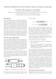
<strong>LTC1668</strong>, 16-Bit, 50Msps DAC<br />
5V<br />
0.1µF<br />
<strong>LTC1668</strong> SFDR vs f OUT and f CLOCK<br />
0.1µF<br />
C1<br />
0.1µF<br />
R SET<br />
2k<br />
C2<br />
0.1µF<br />
REFOUT<br />
I REFIN<br />
COMP1<br />
COMP2<br />
V SS<br />
–5V<br />
2.5V<br />
REFERENCE<br />
+<br />
–<br />
0.1µF<br />
V DD<br />
AGND DGND CLK DB15 DB0<br />
CLOCK<br />
INPUT<br />
16-BIT<br />
HIGH SPEED<br />
DAC<br />
16-BIT DATA<br />
INPUT<br />
<strong>LTC1668</strong><br />
I OUT A<br />
LADCOM<br />
1666/7/8 TA01<br />
52.3Ω<br />
I OUT B<br />
52.3Ω V OUT<br />
1V P-P<br />
DIFFERENTIAL<br />
+<br />
–<br />
SFDR (dB)<br />
100<br />
90<br />
80<br />
70<br />
60<br />
50<br />
0.1<br />
5MSPS<br />
25MSPS<br />
50MSPS<br />
DIGITAL AMPLITUDE = 0dBFS<br />
1.0 10 100<br />
f OUT (MHz)<br />
1666/7/8 G05<br />
1
<strong>LTC1666</strong>/<strong>LTC1667</strong>/<strong>LTC1668</strong><br />
ABSOLUTE AXI U RATI GS<br />
W W W<br />
Supply Voltage (V DD ) ................................................ 6V<br />
Negative Supply Voltage (V SS ) ............................... –6V<br />
Total Supply Voltage (V DD to V SS ) .......................... 12V<br />
Digital Input Voltage .................... –0.3V to (V DD + 0.3V)<br />
Analog Output Voltage<br />
(I OUT A and I OUT B ) ........ (V SS – 0.3V) to (V DD + 0.3V)<br />
U U W<br />
PACKAGE/ORDER I FOR ATIO<br />
U<br />
(Note 1)<br />
Power Dissipation............................................. 500mW<br />
Operating Temperature Range<br />
<strong>LTC1666</strong>C/<strong>LTC1667</strong>C/<strong>LTC1668</strong>C ........... 0°C to 70°C<br />
<strong>LTC1666</strong>I/<strong>LTC1667</strong>I/<strong>LTC1668</strong>I .......... –40°C to 85°C<br />
Storage Temperature Range ................ – 65°C to 150°C<br />
Lead Temperature (Soldering, 10 sec).................. 300°C<br />
DB9<br />
DB8<br />
DB7<br />
DB6<br />
1<br />
2<br />
3<br />
4<br />
TOP VIEW<br />
28<br />
27<br />
26<br />
25<br />
DB10<br />
DB11 (MSB)<br />
CLK<br />
V DD<br />
ORDER PART<br />
NUMBER<br />
<strong>LTC1666</strong>CG<br />
<strong>LTC1666</strong>IG<br />
DB5<br />
5<br />
24<br />
DGND<br />
DB4<br />
6<br />
23<br />
V SS<br />
DB3<br />
7<br />
22<br />
COMP2<br />
DB2<br />
8<br />
21<br />
COMP1<br />
DB1<br />
9<br />
20<br />
I OUT A<br />
DB0 (LSB)<br />
10<br />
19<br />
I OUT B<br />
NC<br />
11<br />
18<br />
LADCOM<br />
NC<br />
12<br />
17<br />
AGND<br />
NC<br />
13<br />
16<br />
I REFIN<br />
NC<br />
14<br />
15<br />
REFOUT<br />
G PACKAGE<br />
28-LEAD PLASTIC SSOP<br />
T JMAX = 110°C, θ JA = 100°C/W<br />
DB11<br />
DB10<br />
DB9<br />
DB8<br />
DB7<br />
DB6<br />
DB5<br />
DB4<br />
DB3<br />
DB2<br />
DB1<br />
DB0 (LSB)<br />
NC<br />
NC<br />
1<br />
2<br />
3<br />
4<br />
5<br />
6<br />
7<br />
8<br />
9<br />
10<br />
11<br />
12<br />
13<br />
14<br />
TOP VIEW<br />
28<br />
27<br />
26<br />
25<br />
24<br />
23<br />
22<br />
21<br />
20<br />
19<br />
18<br />
17<br />
16<br />
15<br />
DB12<br />
DB13 (MSB)<br />
CLK<br />
V DD<br />
DGND<br />
V SS<br />
COMP2<br />
COMP1<br />
I OUT A<br />
I OUT B<br />
LADCOM<br />
AGND<br />
I REFIN<br />
REFOUT<br />
ORDER PART<br />
NUMBER<br />
<strong>LTC1667</strong>CG<br />
<strong>LTC1667</strong>IG<br />
DB13<br />
DB12<br />
DB11<br />
DB10<br />
DB9<br />
DB8<br />
DB7<br />
DB6<br />
DB5<br />
DB4<br />
DB3<br />
DB2<br />
DB1<br />
DB0 (LSB)<br />
1<br />
2<br />
3<br />
4<br />
5<br />
6<br />
7<br />
8<br />
9<br />
10<br />
11<br />
12<br />
13<br />
14<br />
TOP VIEW<br />
28<br />
27<br />
26<br />
25<br />
24<br />
23<br />
22<br />
21<br />
20<br />
19<br />
18<br />
17<br />
16<br />
15<br />
DB14<br />
DB15 (MSB)<br />
CLK<br />
V DD<br />
DGND<br />
V SS<br />
COMP2<br />
COMP1<br />
I OUT A<br />
I OUT B<br />
LADCOM<br />
AGND<br />
I REFIN<br />
REFOUT<br />
ORDER PART<br />
NUMBER<br />
<strong>LTC1668</strong>CG<br />
<strong>LTC1668</strong>IG<br />
G PACKAGE<br />
28-LEAD PLASTIC SSOP<br />
T JMAX = 110°C, θ JA = 100°C/W<br />
G PACKAGE<br />
28-LEAD PLASTIC SSOP<br />
T JMAX = 110°C, θ JA = 100°C/W<br />
Consult LTC Marketing for parts specified with wider operating temperature ranges.<br />
2
<strong>LTC1666</strong>/<strong>LTC1667</strong>/<strong>LTC1668</strong><br />
ELECTRICAL CHARACTERISTICS The ● denotes specifications which apply over the full operating<br />
temperature range, otherwise specifications are at T A = 25°C. V DD = 5V, V SS = –5V, LADCOM = AGND = DGND = 0V, I OUTFS = 10mA.<br />
<strong>LTC1666</strong> <strong>LTC1667</strong> <strong>LTC1668</strong><br />
SYMBOL PARAMETER CONDITIONS MIN TYP MAX MIN TYP MAX MIN TYP MAX UNITS<br />
DC Accuracy (Measured at I OUT A , Driving a Virtual Ground)<br />
Resolution ● 12 14 16 Bits<br />
Monotonicity 12 14 14 Bits<br />
INL Integral Nonlinearity (Note 2) ±1 ±2 ±8 LSB<br />
DNL Differential Nonlinearity (Note 2) ±1 ±1 ±1 ±4 LSB<br />
Offset Error 0.1 ±0.2 0.1 ±0.2 0.1 ±0.2 % FSR<br />
Offset Error Drift 5 5 5 ppm/°C<br />
GE Gain Error Internal Reference, R IREFIN = 2k 2 2 2 % FSR<br />
External Reference, 1 1 1 % FSR<br />
V REF = 2.5V, R IREFIN = 2k<br />
Gain Error Drift Internal Reference 50 50 50 ppm/°C<br />
External Reference 30 30 30 ppm/°C<br />
PSRR Power Supply V DD = 5V ±5% ±0.1 ±0.1 ±0.1 % FSR/V<br />
Rejection Ratio V SS = –5V ±5% ±0.2 ±0.2 ±0.2 % FSR/V<br />
AC Linearity<br />
SFDR Spurious Free Dynamic f CLK = 25Msps, f OUT = 1MHz<br />
Range to Nyquist 0dB FS Output 76 78 78 87 dB<br />
–6dB FS Output 87 dB<br />
–12dB FS Output 83 dB<br />
f CLK = 50Msps, f OUT = 1MHz 85 dB<br />
f CLK = 50Msps, f OUT = 2.5MHz 81 dB<br />
f CLK = 50Msps, f OUT = 5MHz 79 dB<br />
f CLK = 50Msps, f OUT = 20MHz 70 dB<br />
Spurious Free Dynamic f CLK = 25Msps, 85 86 86 96 dB<br />
Range Within a Window f OUT = 1MHz, 2MHz Span<br />
f CLK = 50Msps, 88 dB<br />
f OUT = 5MHz, 4MHz Span<br />
THD Total Harmonic Distortion f CLK = 25Msps, f OUT = 1MHz –75 –77 – 84 – 77 dB<br />
f CLK = 50Msps, f OUT = 5MHz – 78 dB<br />
3
<strong>LTC1666</strong>/<strong>LTC1667</strong>/<strong>LTC1668</strong><br />
ELECTRICAL CHARACTERISTICS The ● denotes specifications which apply over the full operating<br />
temperature range, otherwise specifications are at T A = 25°C. V DD = 5V, V SS = –5V, LADCOM = AGND = DGND = 0V, I OUTFS = 10mA.<br />
<strong>LTC1666</strong>/<strong>LTC1667</strong>/<strong>LTC1668</strong><br />
SYMBOL PARAMETER CONDITIONS MIN TYP MAX UNITS<br />
Analog Output<br />
I OUTFS Full-Scale Output Current ● 1 10 mA<br />
Output Compliance Range I FS = 10mA ● –1 1 V<br />
Output Resistance; R IOUT A , R IOUT B I OUT A, B to LADCOM ● 0.7 1.1 1.5 kΩ<br />
Reference Output<br />
Output Capacitance 5 pF<br />
Reference Voltage REFOUT Tied to I REFIN Through 2kΩ 2.475 2.5 2.525 V<br />
Reference Output Drift 25 ppm/°C<br />
Reference Output Load Regulation I LOAD = 0mA to 5mA 6 mV/mA<br />
Reference Input<br />
Power Supply<br />
Reference Small-Signal Bandwidth I FS = 10mA, C COMP1 = 0.1µF 20 kHz<br />
V DD Positive Supply Voltage ● 4.75 5 5.25 V<br />
V SS Negative Supply Voltage ● –4.75 –5 –5.25 V<br />
I DD Positive Supply Current I FS = 10mA, f CLK = 25Msps, f OUT = 1MHz ● 3 5 mA<br />
I SS Negative Supply Current I FS = 10mA, f CLK = 25Msps, f OUT = 1MHz ● 33 40 mA<br />
P DIS Power Dissipation I FS = 10mA, f CLK = 25Msps, f OUT = 1MHz 180 mW<br />
I FS = 1mA, f CLK = 25Msps, f OUT = 1MHz 85 mW<br />
Dynamic Performance (Differential Transformer Coupled Output, 50Ω Double Terminated, Unless Otherwise Noted)<br />
f CLOCK Maximum Update Rate ● 50 75 Msps<br />
t S Output Settling Time To 0.1% FSR 20 ns<br />
t PD Output Propagation Delay 8 ns<br />
Glitch Impulse Single Ended 15 pV-s<br />
Differential 5 pV-s<br />
t r Output Rise Time 4 ns<br />
t f Output Fall Time 4 ns<br />
i NO Output Noise 50 pA/√Hz<br />
Digital Inputs<br />
V IH Digital High Input Voltage ● 2.4 V<br />
V IL Digital Low Input Voltage ● 0.8 V<br />
I IN Digital Input Current ● ±10 µA<br />
C IN Digital Input Capacitance 5 pF<br />
t DS Input Setup Time ● 8 ns<br />
t DH Input Hold Time ● 4 ns<br />
t CLKH Clock High Time ● 5 ns<br />
t CLKL Clock Low Time ● 8 ns<br />
Note 1: Absolute Maximum Ratings are those values beyond which the life<br />
of the device may be impaired.<br />
Note 2: For the <strong>LTC1666</strong>, ±1LSB = ±0.024% of full scale;<br />
for the <strong>LTC1667</strong>, ±1LSB = ±0.006% of full scale = ±61ppm of full scale;<br />
for the <strong>LTC1668</strong>, ±1LSB = ±0.0015% of full scale = ±15.3ppm of full scale.<br />
4
<strong>LTC1666</strong>/<strong>LTC1667</strong>/<strong>LTC1668</strong><br />
<strong>TYPICAL</strong> PERFOR A CE CHARACTERISTICS<br />
UW<br />
(<strong>LTC1668</strong>)<br />
SIGNAL AMPLITUDE (dBFS)<br />
Single Tone SFDR at 50MSPS<br />
0<br />
SFDR = 87dB<br />
–10<br />
f CLOCK = 50MSPS<br />
–20<br />
f OUT = 1.002MHz<br />
AMPL = 0dBFS<br />
–30<br />
= –8.25dBm<br />
–40<br />
–50<br />
–60<br />
–70<br />
–80<br />
–90<br />
–100<br />
0 5 10 15 20 25<br />
FREQUENCY (MHz)<br />
1666/7/8 G01<br />
SIGNAL AMPLITUDE (dBFS)<br />
0<br />
–10<br />
–20<br />
–30<br />
–40<br />
–50<br />
–60<br />
–70<br />
–80<br />
–90<br />
2-Tone SFDR<br />
SFDR > 86dB<br />
f CLOCK = 50MSPS<br />
f OUT1 = 4.9MHz<br />
f OUT2 = 5.09MHz<br />
AMPL = 0dBFS<br />
–100<br />
4.5 5.0 5.5<br />
FREQUENCY (MHz)<br />
1666/7/8 G02<br />
SIGNAL AMPLITUDE (dBFS)<br />
4-Tone SFDR, f CLOCK = 50MSPS<br />
0<br />
–10<br />
–20<br />
SFDR > 74dB<br />
–30<br />
f CLOCK = 50MSPS<br />
–40<br />
f OUT1 = 5.02MHz<br />
f OUT2 = 6.51MHz<br />
–50<br />
f OUT3 = 11.02MHz<br />
–60<br />
f OUT4 = 12.51MHz<br />
AMPL = 0dBFS<br />
–70<br />
–80<br />
–90<br />
–100<br />
–110<br />
1 4.6 8.2 11.8 15.4 19<br />
FREQUENCY (MHz)<br />
1666/7/8 G03<br />
SIGNAL AMPLITUDE (dBFS)<br />
4-Tone SFDR, f CLOCK = 5MSPS<br />
0<br />
–10<br />
–20<br />
–30<br />
–40<br />
–50<br />
–60<br />
SFDR > 82dB<br />
f CLOCK = 5MSPS<br />
f OUT1 = 0.5MHz<br />
f OUT2 = 0.65MHz<br />
f OUT3 = 1.10MHz<br />
f OUT4 = 1.25MHz<br />
AMPL = 0dBFS<br />
–70<br />
–80<br />
–90<br />
–100<br />
–110<br />
0.1 0.46 0.82 1.18 1.54 1.9<br />
FREQUENCY (MHz)<br />
SFDR (dB)<br />
100<br />
90<br />
80<br />
70<br />
60<br />
50<br />
0.1<br />
SFDR vs f OUT and f CLOCK<br />
5MSPS<br />
25MSPS<br />
50MSPS<br />
DIGITAL AMPLITUDE = 0dBFS<br />
1.0 10 100<br />
f OUT (MHz)<br />
SFDR (dB)<br />
SFDR vs f OUT and Digital Amplitude<br />
(dBFS) at f CLOCK = 5MSPS<br />
100<br />
95<br />
90<br />
85<br />
0dBFS<br />
–6dBFS<br />
–12dBFS<br />
80<br />
75<br />
70<br />
65<br />
60<br />
55<br />
50<br />
0 0.4 0.8 1.2 1.6 2.0<br />
f OUT (MHz)<br />
1666/7/8 G04<br />
1666/7/8 G05<br />
1666/7/8 G06<br />
SFDR (dB)<br />
95<br />
90<br />
85<br />
80<br />
75<br />
70<br />
65<br />
60<br />
SFDR vs f OUT and Digital Amplitude<br />
(dBFS) at f CLOCK = 25MSPS<br />
–6dBFS<br />
0dBFS<br />
–12dBFS<br />
SFDR (dB)<br />
90<br />
85<br />
80<br />
75<br />
70<br />
65<br />
60<br />
SFDR vs f OUT and Digital Amplitude<br />
(dBFS) at f CLOCK = 50MSPS<br />
0dBFS<br />
–12dBFS<br />
–6dBFS<br />
SFDR (dB)<br />
95<br />
90<br />
85<br />
80<br />
75<br />
70<br />
65<br />
60<br />
SFDR vs f OUT and I OUTFS at<br />
f CLOCK = 25MSPS<br />
I OUTFS = 2.5mA<br />
DIGITAL AMPLITUDE = 0dBFS<br />
I OUTFS = 10mA<br />
I OUTFS = 5mA<br />
55<br />
55<br />
55<br />
50<br />
0<br />
2 4 6 8 10<br />
f OUT (MHz)<br />
50<br />
0<br />
5 10 15 20<br />
f OUT (MHz)<br />
50<br />
0<br />
2.5 5 7.5<br />
f OUT (MHz)<br />
10<br />
1666/7/8 G07<br />
1666/7/8 G08<br />
1666/7/8 G09<br />
5
<strong>LTC1666</strong>/<strong>LTC1667</strong>/<strong>LTC1668</strong><br />
<strong>TYPICAL</strong> PERFOR A CE CHARACTERISTICS<br />
UW<br />
(<strong>LTC1668</strong>)<br />
100<br />
SFDR vs Digital Amplitude (dBFS)<br />
and f CLOCK at f OUT = f CLOCK /11<br />
100<br />
SFDR vs Digital Amplitude (dBFS)<br />
and f CLOCK at f OUT = f CLOCK /5<br />
Single-Ended Outputs<br />
Full-Scale Transition<br />
95<br />
90<br />
455kHz AT 5MSPS<br />
95<br />
90<br />
1MHz AT 5MSPS<br />
SFDR (dB)<br />
85<br />
80<br />
75<br />
70<br />
65<br />
4.55MHz AT 50MSPS<br />
2.277MHz AT 25MSPS<br />
SFDR (dB)<br />
85<br />
80<br />
75<br />
70<br />
65<br />
5MHz AT 25MSPS<br />
10MHz AT 50MSPS<br />
100mV<br />
/DIV<br />
0000<br />
FFFF<br />
V(I OUTB )<br />
V(I OUTA )<br />
60<br />
55<br />
50<br />
–20 –15 –10 –5 0<br />
DIGITAL AMPLITUDE (dBFS)<br />
60<br />
55<br />
50<br />
–20 –15 –10 –5 0<br />
DIGITAL AMPLITUDE (dBFS)<br />
CLK IN<br />
5V/DIV<br />
CLOCK INPUT<br />
5ns/DIV<br />
1666/7/8 G12<br />
1666/7/8 G10<br />
1666/7/8 G11<br />
Differential Output<br />
Full-Scale Transition<br />
Single-Ended Output<br />
Full-Scale Transition<br />
Differential Output<br />
Full-Scale Transition<br />
V(I OUTA ) – V(I OUTB )<br />
V(I OUTA ) – V(I OUTB )<br />
V(I OUTA )<br />
100mV<br />
/DIV<br />
0000<br />
FFFF<br />
100mV<br />
/DIV<br />
FFFF 0000<br />
100mV<br />
/DIV<br />
FFFF 0000<br />
V(I OUTB )<br />
CLK IN<br />
5V/DIV<br />
5ns/DIV<br />
CLK IN<br />
5V/DIV<br />
CLOCK INPUT<br />
5ns/DIV<br />
CLK IN<br />
5V/DIV<br />
5ns/DIV<br />
1666/7/8 G13<br />
1666/7/8 G14<br />
1666/7/8 G15<br />
Single-Ended Midscale<br />
Glitch Impulse<br />
V(I OUTA ), V(I OUTB )<br />
Differential Midscale<br />
Glitch Impulse<br />
V(I OUTA ) – V(I OUTB )<br />
5<br />
4<br />
Integral Nonlinearity<br />
1mV/DIV<br />
CLK IN<br />
5V/DIV<br />
7FFF 8000<br />
1mV/DIV<br />
CLK IN<br />
5V/DIV<br />
7FFF 8000<br />
INTEGRAL NONLINEARITY (LSB)<br />
3<br />
2<br />
1<br />
0<br />
–1<br />
–2<br />
–3<br />
–4<br />
5ns/DIV<br />
1666/7/8 G16<br />
5ns/DIV<br />
1666/7/8 G17<br />
–5<br />
16384 32768 49152 65535<br />
DIGITAL INPUT CODE<br />
1666/7/8 G18<br />
6
<strong>LTC1666</strong>/<strong>LTC1667</strong>/<strong>LTC1668</strong><br />
<strong>TYPICAL</strong> PERFOR A CE CHARACTERISTICS<br />
UW<br />
(<strong>LTC1668</strong>)<br />
2.0<br />
Differential Nonlinearity<br />
DIFFERENTIAL NONLINEARITY (LSB)<br />
1.5<br />
1.0<br />
0.5<br />
0<br />
–0.5<br />
–1.0<br />
–1.5<br />
–2.0<br />
0<br />
16384 32768 49152<br />
DIGITAL INPUT CODE<br />
65535<br />
1666/7/8 G19<br />
PI FU CTIO S<br />
U U U<br />
<strong>LTC1666</strong><br />
REFOUT (Pin 15): Internal Reference Voltage Output.<br />
Nominal value is 2.5V. Requires a 0.1µF bypass capacitor<br />
to AGND.<br />
I REFIN (Pin 16): Reference Input Current. Nominal value is<br />
1.25mA for I FS = 10mA. I FS = I REFIN • 8.<br />
AGND (Pin 17): Analog Ground.<br />
LADCOM (Pin 18): Attenuator Ladder Common. Normally<br />
tied to GND.<br />
I OUT B (Pin 19): Complementary DAC Output Current. Fullscale<br />
output current occurs when all data bits are 0s.<br />
I OUT A (Pin 20): DAC Output Current. Full-scale output<br />
current occurs when all data bits are 1s.<br />
COMP1 (Pin 21): Current Source Control Amplifier Compensation.<br />
Bypass to V SS with 0.1µF.<br />
COMP2 (Pin 22): Internal Bypass Point. Bypass to V SS<br />
with 0.1µF.<br />
V SS (Pin 23): Negative Supply Voltage. Nominal value is<br />
–5V.<br />
DGND (Pin 24): Digital Ground.<br />
V DD (Pin 25): Positive Supply Voltage. Nominal value is 5V.<br />
CLK (Pin 26): Clock Input. Data is latched and the output<br />
is updated on positive edge of clock.<br />
DB11 to DB0 (Pins 27, 28, 1 to 10 ): Digital Input Data Bits.<br />
7
<strong>LTC1666</strong>/<strong>LTC1667</strong>/<strong>LTC1668</strong><br />
PI FU CTIO S<br />
U U U<br />
<strong>LTC1667</strong><br />
REFOUT (Pin 15): Internal Reference Voltage Output.<br />
Nominal value is 2.5V. Requires a 0.1µF bypass capacitor<br />
to AGND.<br />
I REFIN (Pin 16): Reference Input Current. Nominal value is<br />
1.25mA for I FS = 10mA. I FS = I REFIN • 8.<br />
AGND (Pin 17): Analog Ground.<br />
LADCOM (Pin 18): Attenuator Ladder Common. Normally<br />
tied to GND.<br />
I OUT B (Pin 19): Complementary DAC Output Current. Fullscale<br />
output current occurs when all data bits are 0s.<br />
I OUT A (Pin 20): DAC Output Current. Full-scale output<br />
current occurs when all data bits are 1s.<br />
COMP1 (Pin 21): Current Source Control Amplifier Compensation.<br />
Bypass to V SS with 0.1µF.<br />
COMP2 (Pin 22): Internal Bypass Point. Bypass to V SS<br />
with 0.1µF.<br />
V SS (Pin 23): Negative Supply Voltage. Nominal value is<br />
–5V.<br />
DGND (Pin 24): Digital Ground.<br />
V DD (Pin 25): Positive Supply Voltage. Nominal value is 5V.<br />
CLK (Pin 26): Clock Input. Data is latched and the output<br />
is updated on positive edge of clock.<br />
DB13 to DB0 (Pins 27, 28, 1 to 12 ): Digital Input Data Bits.<br />
<strong>LTC1668</strong><br />
REFOUT (Pin 15): Internal Reference Voltage Output.<br />
Nominal value is 2.5V. Requires a 0.1µF bypass capacitor<br />
to AGND.<br />
I REFIN (Pin 16): Reference Input Current. Nominal value is<br />
1.25mA for I FS = 10mA. I FS = I REFIN • 8.<br />
AGND (Pin 17): Analog Ground.<br />
LADCOM (Pin 18): Attenuator Ladder Common. Normally<br />
tied to GND.<br />
I OUT B (Pin 19): Complementary DAC Output Current. Fullscale<br />
output current occurs when all data bits are 0s.<br />
I OUT A (Pin 20): DAC Output Current. Full-scale output<br />
current occurs when all data bits are 1s.<br />
COMP1 (Pin 21): Current Source Control Amplifier Compensation.<br />
Bypass to V SS with 0.1µF.<br />
COMP2 (Pin 22): Internal Bypass Point. Bypass to V SS<br />
with 0.1µF.<br />
V SS (Pin 23): Negative Supply Voltage. Nominal value is<br />
–5V.<br />
DGND (Pin 24): Digital Ground.<br />
V DD (Pin 25): Positive Supply Voltage. Nominal value is 5V.<br />
CLK (Pin 26): Clock Input. Data is latched and the output<br />
is updated on positive edge of clock.<br />
DB15 to DB0 (Pins 27, 28, 1 to 14 ): Digital Input Data Bits.<br />
8
<strong>LTC1666</strong>/<strong>LTC1667</strong>/<strong>LTC1668</strong><br />
BLOCK DIAGRA<br />
W<br />
<strong>LTC1666</strong><br />
5V<br />
0.1µF<br />
25<br />
V DD<br />
LADCOM<br />
18<br />
0.1µF<br />
V REF 15<br />
REFOUT<br />
2.5V<br />
REFERENCE<br />
ATTENUATOR<br />
LADDER<br />
52.3Ω 52.3Ω<br />
I OUT A 20<br />
+ V OUT<br />
I OUT B 19<br />
1V P-P<br />
DIFFERENTIAL<br />
–<br />
R SET<br />
2k<br />
16<br />
I REFIN<br />
I FS /8<br />
LSB SWITCHES<br />
SEGMENTED SWITCHES<br />
FOR DB15–DB12<br />
+<br />
–<br />
I INT<br />
CURRENT SOURCE ARRAY<br />
• • • • • •<br />
21<br />
COMP1<br />
0.1µF<br />
22<br />
0.1µF<br />
COMP2<br />
V SS<br />
AGND<br />
DGND<br />
CLK<br />
DB11<br />
INPUT LATCHES<br />
• • •<br />
DB0<br />
–5V<br />
23<br />
0.1µF<br />
17<br />
24<br />
CLOCK<br />
INPUT<br />
26 27 10<br />
1666 BD<br />
• • •<br />
12-BIT<br />
DATA INPUT<br />
<strong>LTC1667</strong><br />
5V<br />
0.1µF<br />
25<br />
V DD<br />
LADCOM<br />
18<br />
0.1µF<br />
V REF 15<br />
REFOUT<br />
2.5V<br />
REFERENCE<br />
ATTENUATOR<br />
LADDER<br />
52.3Ω 52.3Ω<br />
I OUT A 20<br />
+ V OUT<br />
I OUT B 19<br />
1V P-P<br />
DIFFERENTIAL<br />
–<br />
R SET<br />
2k<br />
16<br />
I REFIN<br />
I FS /8<br />
LSB SWITCHES<br />
SEGMENTED SWITCHES<br />
FOR DB15–DB12<br />
+<br />
–<br />
I INT<br />
CURRENT SOURCE ARRAY<br />
• • • • • •<br />
21<br />
COMP1<br />
0.1µF<br />
22<br />
0.1µF<br />
COMP2<br />
V SS<br />
AGND<br />
DGND<br />
CLK<br />
DB13<br />
INPUT LATCHES<br />
• • •<br />
DB0<br />
–5V<br />
23<br />
0.1µF<br />
17<br />
24<br />
CLOCK<br />
INPUT<br />
26 27 12<br />
1667 BD<br />
• • •<br />
14-BIT<br />
DATA INPUT<br />
9
<strong>LTC1666</strong>/<strong>LTC1667</strong>/<strong>LTC1668</strong><br />
BLOCK DIAGRA<br />
W<br />
<strong>LTC1668</strong><br />
5V<br />
0.1µF<br />
25<br />
V DD<br />
LADCOM<br />
18<br />
0.1µF<br />
V REF 15<br />
REFOUT<br />
2.5V<br />
REFERENCE<br />
ATTENUATOR<br />
LADDER<br />
52.3Ω 52.3Ω<br />
I OUT A 20<br />
+ V OUT<br />
I OUT B 19<br />
1V P-P<br />
DIFFERENTIAL<br />
–<br />
R SET<br />
2k<br />
16<br />
I REFIN<br />
I FS /8<br />
LSB SWITCHES<br />
SEGMENTED SWITCHES<br />
FOR DB15–DB12<br />
+<br />
–<br />
I INT<br />
CURRENT SOURCE ARRAY<br />
• • • • • •<br />
21<br />
COMP1<br />
0.1µF<br />
22<br />
0.1µF<br />
COMP2<br />
V SS<br />
AGND<br />
DGND<br />
CLK<br />
DB15<br />
INPUT LATCHES<br />
• • •<br />
DB0<br />
–5V<br />
23<br />
0.1µF<br />
17<br />
24<br />
CLOCK<br />
INPUT<br />
26 27 14<br />
1668 BD<br />
• • •<br />
16-BIT<br />
DATA INPUT<br />
U W<br />
W<br />
TI I G DIAGRA<br />
DATA<br />
INPUT<br />
N – 1<br />
N N + 1<br />
t DS<br />
t DH<br />
CLK<br />
t CLKL t CLKH<br />
t ST<br />
t PD<br />
I OUT A /I OUT B N – 1<br />
N 0.1%<br />
1666/7/8 TD<br />
10
<strong>LTC1666</strong>/<strong>LTC1667</strong>/<strong>LTC1668</strong><br />
<strong>APPLICATIO</strong> S I FOR ATIO<br />
Theory of Operation<br />
U W U U<br />
The <strong>LTC1666</strong>/<strong>LTC1667</strong>/<strong>LTC1668</strong> are high speed current<br />
steering 12-/14-/16-bit DACs made on an advanced<br />
BiCMOS process. Precision thin film resistors and well<br />
matched bipolar transistors result in excellent DC linearity<br />
and stability. A low glitch current switching design gives<br />
excellent AC performance at sample rates up to 50Msps.<br />
The devices are complete with a 2.5V internal bandgap<br />
reference and edge triggered latches, and set a new<br />
standard for DAC applications requiring very high dynamic<br />
range at output frequencies up to several megahertz.<br />
Referring to the Block Diagrams, the DACs contain an<br />
array of current sources that are steered to I OUTA or I OUTB<br />
with NMOS differential current switches. The four most<br />
significant bits are made up of 15 current segments of<br />
equal weight. The remaining lower bits are binary weighted,<br />
using a combination of current scaling and a differential<br />
resistive attenuator ladder. All bits and segments are<br />
precisely matched, both in current weight for DC linearity,<br />
and in switch timing for low glitch impulse and low<br />
spurious tone AC performance.<br />
Setting the Full-Scale Current, I OUTFS<br />
The full-scale DAC output current, I OUTFS , is nominally<br />
10mA, and can be adjusted down to 1mA. Placing a<br />
resistor, R SET , between the REFOUT pin, and the I REFIN pin<br />
sets I OUTFS as follows.<br />
The internal reference control loop amplifier maintains a<br />
virtual ground at I REFIN by servoing the internal current<br />
source, I INT , to sink the exact current flowing into I REFIN .<br />
I INT is a scaled replica of the DAC current sources and<br />
I OUTFS = 8 • (I INT ), therefore:<br />
I OUTFS = 8 • (I REFIN ) = 8 • (V REF /R SET ) (1)<br />
For example, if R SET = 2k and is tied to V REF = REFOUT =<br />
2.5V, I REFIN = 2.5/2k = 1.25mA and I OUTFS = 8 • (1.25mA)<br />
= 10mA.<br />
The reference control loop requires a capacitor on the<br />
COMP1 pin for compensation. For optimal AC performance,<br />
C COMP1 should be connected to V SS and be placed<br />
very close to the package (less than 0.1").<br />
For fixed reference voltage applications, C COMP1 should<br />
be 0.1µF or more. The reference control loop small-signal<br />
bandwidth is approximately 1/(2π) • C COMP1 • 80 or 20kHz<br />
for C COMP1 = 0.1µF.<br />
Reference Operation<br />
The onboard 2.5V bandgap voltage reference drives the<br />
REFOUT pin. It is trimmed and specified to drive a 2k<br />
resistor tied from REFOUT to I REFIN , corresponding to a<br />
1.25mA load (I OUTFS = 10mA). REFOUT has nominal<br />
output impedance of 6Ω, or 0.24% per mA, so it must be<br />
buffered to drive any additional external load. A 0.1µF<br />
capacitor is required on the REFOUT pin for compensation.<br />
Note that this capacitor is required for stability, even<br />
if the internal reference is not being used.<br />
External Reference Operation<br />
Figure 1, shows how to use an external reference to control<br />
the <strong>LTC1666</strong>/<strong>LTC1667</strong>/<strong>LTC1668</strong> full-scale current.<br />
5V<br />
EXTERNAL<br />
REFERENCE<br />
0.1µF<br />
REFOUT<br />
R SET<br />
2.5V<br />
REFERENCE<br />
<strong>LTC1666</strong>/<br />
<strong>LTC1667</strong>/<br />
I REFIN <strong>LTC1668</strong><br />
Figure 1. Using the <strong>LTC1666</strong>/<strong>LTC1667</strong>/<strong>LTC1668</strong><br />
with an External Reference<br />
+<br />
–<br />
1666/7/8 F02<br />
11
<strong>LTC1666</strong>/<strong>LTC1667</strong>/<strong>LTC1668</strong><br />
<strong>APPLICATIO</strong> S I FOR ATIO<br />
U W U U<br />
Adjusting the Full-Scale Output<br />
In Figure 2, a serial interfaced DAC is used to set I OUTFS .<br />
The LTC1661 is a dual 10-bit V OUT DAC with a buffered<br />
voltage output that swings from 0V to V REF .<br />
5V<br />
REF<br />
1/2 LTC1661<br />
0.1µF<br />
R SET<br />
1.9k<br />
2.5V<br />
REFERENCE<br />
<strong>LTC1666</strong>/<br />
<strong>LTC1667</strong>/<br />
I REFIN <strong>LTC1668</strong><br />
Figure 2. Adjusting the Full-Scale Current of<br />
the <strong>LTC1666</strong>/<strong>LTC1667</strong>/<strong>LTC1668</strong> with a DAC<br />
DAC Transfer Function<br />
The <strong>LTC1666</strong>/<strong>LTC1667</strong>/<strong>LTC1668</strong> use straight binary digital<br />
coding. The complementary current outputs, I OUT A and I OUT<br />
B, sink current from 0 to I OUTFS . For I OUTFS = 10mA (nominal),<br />
I OUT A swings from 0mA when all bits are low (e.g.,<br />
Code␣ = 0) to 10mA when all bits are high (e.g., Code = 65535<br />
for <strong>LTC1668</strong>) (decimal representation). I OUT B is complementary<br />
to I OUT A . I OUT A and I OUT B are given by the following<br />
formulas:<br />
<strong>LTC1666</strong>:<br />
I OUT A = I OUTFS • (DAC Code/4096) (2)<br />
I OUT B = I OUTFS • (4095 – DAC Code)/4096 (3)<br />
<strong>LTC1667</strong>:<br />
I OUT A = I OUTFS • (DAC Code/16384) (4)<br />
I OUT B = I OUTFS • (16383 – DAC Code)/16384 (5)<br />
<strong>LTC1668</strong>:<br />
I OUT A = I OUTFS • (DAC Code/65536) (6)<br />
I OUT B = I OUTFS • (65535 – DAC Code)/65536 (7)<br />
In typical applications, the <strong>LTC1666</strong>/<strong>LTC1667</strong>/<strong>LTC1668</strong><br />
differential output currents either drive a resistive load<br />
directly or drive an equivalent resistive load through a<br />
transformer, or as the feedback resistor of an I-to-V<br />
converter. The voltage outputs generated by the I OUT A and<br />
I OUT B output currents are then:<br />
+<br />
–<br />
1666/7/8 F03<br />
V OUT A = I OUT A • R LOAD (8)<br />
V OUT B = I OUT B • R LOAD (9)<br />
The differential voltage is:<br />
V DIFF = V OUT A – V OUT B (10)<br />
= (I OUT A – I OUT B ) • (R LOAD )<br />
Substituting the values found earlier for I OUT A , I OUT B and<br />
I OUTFS (<strong>LTC1668</strong>):<br />
V DIFF = {2 • DAC Code – 65535)/65536} • 8 •<br />
(R LOAD /R SET ) • (V REF ) (11)<br />
From these equations some of the advantages of differential<br />
mode operation can be seen. First, any common mode<br />
noise or error on I OUT A and I OUT B is cancelled. Second, the<br />
signal power is twice as large as in the single-ended case.<br />
Third, any errors and noise that multiply times I OUT A and<br />
I OUT B , such as reference or I OUTFS noise, cancel near<br />
midscale, where AC signal waveforms tend to spend the<br />
most time. Fourth, this transfer function is bipolar; e.g. the<br />
output swings positive and negative around a zero output<br />
at mid-scale input, which is more convenient for AC<br />
applications.<br />
Note that the term (R LOAD /R SET ) appears in both the<br />
differential and single-ended transfer functions. This means<br />
that the Gain Error of the DAC depends on the ratio of<br />
R LOAD to R SET , and the Gain Error tempco is affected by the<br />
temperature tracking of R LOAD with R SET . Note also that<br />
the absolute tempco of R LOAD is very critical for DC<br />
nonlinearity. As the DAC output changes from 0mA to<br />
10mA the R LOAD resistor will heat up slightly, and even a<br />
very low tempco can produce enough INL bowing to be<br />
significant at the 16-bit level. This effect disappears with<br />
medium to high frequency AC signals due to the slow<br />
thermal time constant of the load resistor.<br />
Analog Outputs<br />
The <strong>LTC1666</strong>/<strong>LTC1667</strong>/<strong>LTC1668</strong> have two complementary<br />
current outputs, I OUT A and I OUT B (see DAC Transfer<br />
Function). The output impedance of I OUT A and I OUT B<br />
(R IOUT A and R IOUT B ) is typically 1.1kΩ to LADCOM. (See<br />
Figure 3.)<br />
12
<strong>LTC1666</strong>/<strong>LTC1667</strong>/<strong>LTC1668</strong><br />
<strong>APPLICATIO</strong> S I FOR ATIO<br />
<strong>LTC1666</strong>/<strong>LTC1667</strong>/<strong>LTC1668</strong><br />
U W U U<br />
R IOUT B<br />
1.1k<br />
5pF<br />
R IOUT A<br />
1.1k<br />
LADCOM<br />
I OUT A<br />
I OUT B<br />
LADCOM<br />
The LADCOM pin is the common connection for the<br />
internal DAC attenuator ladder. It usually is tied to analog<br />
ground, but more generally it should connect to the same<br />
potential as the load resistors on I OUT A and I OUT B . The<br />
LADCOM pin carries a constant current to V SS of approximately<br />
0.32 • (I OUTFS ), plus any current that flows from<br />
I OUT A and I OUT B through the R IOUT A and R IOUT B resistors.<br />
5pF<br />
Figure 3. Equivalent Analog Output Circuit<br />
18<br />
20<br />
19<br />
23<br />
1666/7/8 F04<br />
52.3Ω<br />
V SS<br />
52.3Ω<br />
–5V<br />
Output Compliance<br />
The specified output compliance voltage range is ±1V. The<br />
DC linearity specifications, INL and DNL, are trimmed and<br />
guaranteed on I OUT A into the virtual ground of an<br />
I-to-V converter, but are typically very good over the full<br />
output compliance range. Above 1V the output current will<br />
start to increase as the DAC current steering switch<br />
impedance decreases, degrading both DC and AC linearity.<br />
Below –1V, the DAC switches will start to approach the<br />
transition from saturation to linear region. This will degrade<br />
AC performance first, due to nonlinear capacitance<br />
and increased glitch impulse. AC distortion performance<br />
is optimal at amplitudes less than ±0.5V P-P on I OUT A and<br />
I OUT B due to nonlinear capacitance and other large-signal<br />
effects. At first glance, it may seem counter-intuitive to<br />
decrease the signal amplitude when trying to optimize<br />
SFDR. However, the error sources that affect AC performance<br />
generally behave as additive currents, so decreasing<br />
the load impedance to reduce signal voltage amplitude<br />
will reduce most spurious signals by the same amount.<br />
5V<br />
0.1µF<br />
0.1µF<br />
R SET<br />
2k<br />
REFOUT<br />
I REFIN<br />
2.5V<br />
REFERENCE<br />
+ 16-BIT<br />
HIGH SPEED<br />
DAC<br />
–<br />
V DD<br />
<strong>LTC1668</strong><br />
I OUT A<br />
I OUT B<br />
110Ω<br />
MINI-CIRCUITS<br />
T1–1T<br />
TO HP3589A<br />
SPECTRUM<br />
ANALYZER<br />
50Ω INPUT<br />
C1<br />
0.1µF<br />
C2<br />
0.1µF<br />
COMP1<br />
COMP2<br />
V SS<br />
AGND DGND CLK DB15 DB0<br />
LADCOM<br />
50Ω<br />
50Ω<br />
–5V<br />
0.1µF<br />
16<br />
DIGITAL<br />
DATA<br />
CLK<br />
IN<br />
OUT 1 OUT 2<br />
HP8110A DUAL<br />
PULSE GENERATOR<br />
CLK<br />
IN<br />
HP1663EA<br />
LOGIC ANALYZER WITH<br />
PATTERN GENERATOR<br />
1666/7/8 F05<br />
LOW JITTER<br />
CLOCK SOURCE<br />
Figure 4. AC Characterization Setup (<strong>LTC1668</strong>)<br />
13
<strong>LTC1666</strong>/<strong>LTC1667</strong>/<strong>LTC1668</strong><br />
<strong>APPLICATIO</strong> S I FOR ATIO<br />
U W U U<br />
Operating with Reduced Output Currents<br />
The <strong>LTC1666</strong>/<strong>LTC1667</strong>/<strong>LTC1668</strong> are specified to operate<br />
with full-scale output current, I OUTFS , from the nominal<br />
10mA down to 1mA. This can be useful to reduce power<br />
dissipation or to adjust full-scale value. However, the DC<br />
and AC accuracy is specified only at I OUTFS = 10mA, and<br />
DC and AC accuracy will fall off significantly at lower I OUTFS<br />
values. At I OUTFS = 1mA, the <strong>LTC1668</strong> INL and DNL<br />
typically degrade to the 14-bit to 13-bit level, compared to<br />
16-bit to 15-bit typical accuracy at 10mA I OUTFS . Increasing<br />
I OUTFS from 1mA, the accuracy improves rapidly,<br />
roughly in proportion to 1/I OUTFS . Note that the AC performance<br />
(SFDR) is affected much more by reduced I OUTFS<br />
than it is by reduced digital amplitude (see Typical Performance<br />
Characteristics). Therefore it is usually better to<br />
make large gain adjustments digitally, keeping I OUTFS<br />
equal to 10mA.<br />
Output Configurations<br />
Based on the specific application requirements, the<br />
<strong>LTC1666</strong>/<strong>LTC1667</strong>/<strong>LTC1668</strong> allow a choice of the best of<br />
several output configurations. Voltage outputs can be<br />
generated by external load resistors, transformer coupling<br />
or with an op amp I-to-V converter. Single-ended DAC<br />
output configurations use only one of the outputs, preferably<br />
I OUT A , to produce a single-ended voltage output.<br />
Differential mode configurations use the difference between<br />
I OUT A and I OUT B to generate an output voltage,<br />
V DIFF , as shown in equation 11. Differential mode gives<br />
much better accuracy in most AC applications. Because<br />
the DAC chip is the point of interface between the digital<br />
input signals and the analog output, some small amount<br />
of noise coupling to I OUT A and I OUT B is unavoidable. Most<br />
of that digital noise is common mode and is canceled by<br />
the differential mode circuit. Other significant digital noise<br />
components can be modeled as V REF or I OUTFS noise. In<br />
single-ended mode, I OUTFS noise is gone at zero scale and<br />
is fully present at full scale. In differential mode, I OUTFS<br />
noise is cancelled at midscale input, corresponding to zero<br />
analog output. Many AC signals, including broadband and<br />
multitone communications signals with high peak to average<br />
ratios, stay mostly near midscale.<br />
Differential Transformer-Coupled Outputs<br />
Differential transformer-coupled output configurations<br />
usually give the best AC performance. An example is<br />
shown in Figure 5. The advantages of transformer coupling<br />
include excellent rejection of common mode distortion<br />
and noise over a broad frequency range and convenient<br />
differential-to-single-ended conversion with isolation<br />
or level shifting. Also, as much as twice the power can<br />
be delivered to the load, and impedance matching can be<br />
accomplished by selecting the appropriate transformer<br />
turns ratio. The center tap on the primary side of the<br />
transformer is tied to ground to provide the DC current<br />
path for I OUT A and I OUT B . For low distortion, the DC<br />
average of the I OUT A and I OUT B currents must be exactly<br />
equal to avoid biasing the core. This is especially important<br />
for compact RF transformers with small cores. The<br />
circuit in Figure 5 uses a Mini-Circuits T1-1T RF transformer<br />
with a 1:1 turns ratio. The load resistance on<br />
I OUT A and I OUT B is equivalent to a single differential<br />
resistor of 50Ω, and the 1:1 turns ratio means the output<br />
impedance from the transformer is 50Ω. Note that the<br />
load resistors are optional, and they dissipate half of the<br />
output power. However, in lab environments or when<br />
driving long transmission lines it is very desirable to have<br />
a 50Ω output impedance. This could also be done with a<br />
50Ω resistor at the transformer secondary, but putting<br />
the load resistors on I OUT A and I OUT B is preferred since<br />
it reduces the current through the transformer. At signal<br />
frequencies lower than about 1MHz, the transformer core<br />
size required to maintain low distortion gets larger, and at<br />
some lower frequencies this becomes impractical.<br />
I OUT A<br />
<strong>LTC1666</strong>/<br />
<strong>LTC1667</strong>/<br />
<strong>LTC1668</strong><br />
I OUT B<br />
50Ω<br />
50Ω<br />
110Ω<br />
MINI-CIRCUITS<br />
T1-1T<br />
R LOAD<br />
1666/7/8 F06<br />
Figure 5. Differential Transformer-Coupled Outputs<br />
14
<strong>LTC1666</strong>/<strong>LTC1667</strong>/<strong>LTC1668</strong><br />
<strong>APPLICATIO</strong> S I FOR ATIO<br />
Resistor Loaded Outputs<br />
U W U U<br />
A differential resistor loaded output configuration is shown<br />
in Figure 6. It is simple and economical, but it can drive<br />
only differential loads with impedance levels and amplitudes<br />
appropriate for the DAC outputs.<br />
The recommended single-ended resistor loaded configuration<br />
is essentially the same circuit as the differential<br />
resistor loaded, case—simply use the I OUT A output,<br />
referred to ground. Rather than tying the unused I OUT B<br />
output to ground, it is preferred to load it with the equivalent<br />
R LOAD of I OUT A . Then I OUT B will still swing with a<br />
waveform complementary to I OUT A .<br />
52.3Ω 52.3Ω<br />
I OUT A<br />
<strong>LTC1666</strong>/<br />
<strong>LTC1667</strong>/<br />
<strong>LTC1668</strong><br />
I OUT B<br />
1666/7/8 F07<br />
Figure 6. Differential Resistor-Loaded Output<br />
Op Amp I to V Converter Outputs<br />
Adding an op amp differential to single-ended converter<br />
circuit to the differential resistor loaded output gives the<br />
circuit of Figure 7.<br />
This circuit complements the capabilities of the transformer-coupled<br />
application at lower frequencies, since<br />
available op amps can deliver good AC distortion performance<br />
at signal frequencies of a few MHz down to DC. The<br />
optional capacitor adds a single real pole of filtering, and<br />
helps reduce distortion by limiting the high frequency<br />
signal amplitude at the op amp inputs. The circuit swings<br />
±1V around ground.<br />
Figure 8 shows a simplified circuit for a single-ended<br />
output using I-to-V converter to produce a unipolar<br />
buffered voltage output. This configuration typically has<br />
the best DC linearity performance, but its AC distortion at<br />
higher frequencies is limited by U1’s slewing capabilities.<br />
Digital Interface<br />
The <strong>LTC1666</strong>/<strong>LTC1667</strong>/<strong>LTC1668</strong> have parallel inputs that<br />
are latched on the rising edge of the clock input. They<br />
accept CMOS levels from either 5V or 3.3V logic and can<br />
accept clock rates of up to 50MHz.<br />
Referring to the Timing Diagram and Block Diagram, the<br />
data inputs go to master-slave latches that update on the<br />
rising edge of the clock. The input logic thresholds, V IH =<br />
2.4V min, V IL = 0.8V max, work with 3.3V or 5V CMOS<br />
levels over temperature. The guaranteed setup time, t DS ,<br />
is 8ns minimum and the hold time, t DH , is 4ns minimum.<br />
The minimum clock high and low times are guaranteed at<br />
6ns and 8ns, respectively. These specifications allow the<br />
<strong>LTC1666</strong>/<strong>LTC1667</strong>/<strong>LTC1668</strong> to be clocked at up to 50Msps<br />
minimum.<br />
For best AC performance, the data and clock waveforms<br />
need to be clean and free of undershoot and overshoot.<br />
Clock and data interconnect lines should be twisted pair,<br />
coax or microstrip, and proper line termination is important.<br />
If the digital input signals to the DAC are considered<br />
as analog AC voltage signals, they are rich in spectral<br />
components over a broad frequency range, usually in-<br />
C OUT<br />
200Ω<br />
I OUT A<br />
–<br />
<strong>LTC1666</strong>/<br />
<strong>LTC1667</strong>/ 60pF<br />
LT1809<br />
<strong>LTC1668</strong><br />
200Ω +<br />
I OUT B<br />
52.3Ω 52.3Ω 500Ω<br />
500Ω<br />
±1V<br />
10dBm<br />
V OUT<br />
I OUT A<br />
<strong>LTC1666</strong>/<br />
<strong>LTC1667</strong>/<br />
<strong>LTC1668</strong><br />
I OUT B<br />
I OUTFS<br />
10mA<br />
200Ω<br />
–<br />
+<br />
R FB<br />
200Ω<br />
U1<br />
LT ® 1812<br />
V OUT<br />
0V TO 2V<br />
LADCOM<br />
1666/7/8 F09<br />
1666/7/8 F08<br />
Figure 7. Differential to Single-Ended Op Amp I-V Converter<br />
Figure 8. Single-Ended Op Amp I to V Converter<br />
15
<strong>LTC1666</strong>/<strong>LTC1667</strong>/<strong>LTC1668</strong><br />
<strong>APPLICATIO</strong> S I FOR ATIO<br />
U W U U<br />
cluding the output signal band of interest. Therefore, any<br />
direct coupling of the digital signals to the analog output<br />
will produce spurious tones that vary with the exact digital<br />
input pattern.<br />
Clock jitter should be minimized to avoid degrading the<br />
noise floor of the device in AC applications, especially<br />
where high output frequencies are being generated. Any<br />
noise coupling from the digital inputs to the clock input will<br />
cause phase modulation of the clock signal and the DAC<br />
waveform, and can produce spurious tones. It is normally<br />
best to place the digital data transitions near the falling<br />
clock edge, well away from the active rising clock edge.<br />
Because the clock signal contains spectral components<br />
only at the sampling frequency and its multiples, it is<br />
usually not a source of in band spurious tones. Overall, it<br />
is better to treat the clock as you would an analog signal<br />
and route it separately from the digital data input signals.<br />
The clock trace should be routed either over the analog<br />
ground plane or over its own section of the ground plane.<br />
The clock line needs to have accurately controlled impedance<br />
and should be well terminated near the <strong>LTC1666</strong>/<br />
<strong>LTC1667</strong>/<strong>LTC1668</strong>.<br />
Printed Circuit Board Layout Considerations—<br />
Grounding, Bypassing and Output Signal Routing<br />
The close proximity of high frequency digital data lines and<br />
high dynamic range, wide-band analog signals makes<br />
clean printed circuit board design and layout an absolute<br />
necessity. Figures 11 to 15 are the printed circuit board<br />
layers for an AC evaluation circuit for the <strong>LTC1668</strong>. Ground<br />
planes should be split between digital and analog sections<br />
as shown. All bypass capacitors should have minimum<br />
trace length and be ceramic 0.1µF or larger with low ESR.<br />
Bypass capacitors are required on V SS , V DD and REFOUT,<br />
and all connected to the AGND plane. The COMP2 pin ties<br />
to a node in the output current switching circuitry, and it<br />
requires a 0.1µF bypass capacitor. It should be bypassed<br />
to V SS along with COMP1. The AGND and DGND pins<br />
should both tie directly to the AGND plane, and the tie point<br />
between the AGND and DGND planes should nominally be<br />
near the DGND pin. LADCOM should either be tied directly<br />
to the AGND plane or be bypassed to AGND. The I OUT A and<br />
I OUT B traces should be close together, short, and well<br />
matched for good AC CMRR. The transformer output<br />
ground should be capable of optionally being isolated or<br />
being tied to the AGND plane, depending on which gives<br />
better performance in the system.<br />
Suggested Evaluation Circuit<br />
Figure 10 is the schematic and Figures 11 to 15 are the<br />
circuit board layouts for a suggested evaluation circuit,<br />
DC245A. The circuit can be programmed with component<br />
selection and jumpers for a variety of differentially coupled<br />
transformer output and differential and single-ended resistor<br />
loaded output configurations.<br />
0.1µF<br />
2k<br />
REFOUT<br />
<strong>LTC1668</strong><br />
U1<br />
I-CHANNEL<br />
LADCOM<br />
I OUT A<br />
I OUT B<br />
52.3Ω<br />
52.3Ω<br />
LOW-PASS<br />
FILTER<br />
QUADRATURE<br />
MODULATOR<br />
SERIAL<br />
INPUT<br />
REF<br />
1/2 LTC1661<br />
U3<br />
V OUT<br />
2.1k<br />
I REFIN<br />
CLK<br />
LOCAL<br />
OSCILLATOR<br />
90° ∑<br />
QAM<br />
OUTPUT<br />
±5%<br />
RELATIVE GAIN<br />
ADJUSTMENT RANGE<br />
21k<br />
0.1µF<br />
REFOUT<br />
<strong>LTC1668</strong><br />
U2<br />
Q-CHANNEL<br />
LADCOM<br />
I OUT A<br />
I OUT B<br />
52.3Ω<br />
52.3Ω<br />
LOW-PASS<br />
FILTER<br />
I REFIN<br />
CLK<br />
CLOCK<br />
INPUT<br />
1666/7/8 F10<br />
16<br />
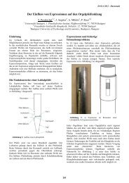
Figure 9. QAM Modulation Using <strong>LTC1668</strong> with<br />
Digitally Controlled I vs Q Channel Gain Adjustment
<strong>LTC1666</strong>/<strong>LTC1667</strong>/<strong>LTC1668</strong><br />
<strong>APPLICATIO</strong> S I FOR ATIO<br />
U W U U<br />
+5VD<br />
+5VD<br />
1<br />
3<br />
5<br />
JP1<br />
2<br />
4<br />
6<br />
RN5<br />
J7<br />
J10<br />
J1<br />
EXTREF<br />
C2<br />
0.1µF<br />
AMP<br />
102159-9<br />
5V<br />
LT1460DCS8-2.5<br />
2<br />
6<br />
4<br />
1<br />
3<br />
5<br />
7<br />
9<br />
2<br />
4<br />
6<br />
8<br />
10<br />
12<br />
14<br />
16<br />
18<br />
20<br />
22<br />
24<br />
26<br />
28<br />
30<br />
32<br />
34<br />
36<br />
38<br />
40<br />
11<br />
13<br />
15<br />
17<br />
19<br />
21<br />
23<br />
25<br />
27<br />
29<br />
31<br />
33<br />
35<br />
37<br />
39<br />
R1<br />
10Ω<br />
VIN VOUT<br />
GND<br />
TP6<br />
TESTPOINT RED<br />
C19<br />
0.1µF<br />
+<br />
C14<br />
10µF<br />
25V<br />
TP1<br />
C1<br />
0.1µF<br />
1<br />
2<br />
3<br />
4<br />
5<br />
6<br />
7<br />
8<br />
22Ω<br />
RN6<br />
1<br />
2<br />
3<br />
4<br />
5<br />
6<br />
7<br />
8<br />
22Ω<br />
TP10<br />
TESTPOINT BLK<br />
TP2<br />
TESTPOINT WHT<br />
2.5V REF<br />
R2<br />
200Ω<br />
16<br />
15<br />
14<br />
13<br />
12<br />
11<br />
10<br />
9<br />
16<br />
15<br />
14<br />
13<br />
12<br />
11<br />
10<br />
9<br />
R3<br />
1.91k<br />
0.1%<br />
C3<br />
0.1µF<br />
16<br />
10<br />
11<br />
12<br />
13<br />
14<br />
26<br />
27<br />
28<br />
1<br />
2<br />
3<br />
4<br />
5<br />
6<br />
7<br />
8<br />
9<br />
REFIN<br />
<strong>LTC1668</strong><br />
REFOUT<br />
DB15 (MSB)<br />
DB14 I OUT A<br />
DB13 IOUT B<br />
DB12<br />
DB11<br />
DB10 LADCOM<br />
DB9 COMP1<br />
DB8 COMP2<br />
DB7<br />
DB6 V SS<br />
DB5 V DD<br />
DB4 AGND<br />
DB3<br />
DB2 DGND<br />
DB1<br />
DB0 (LSB)<br />
CLK<br />
15<br />
20<br />
19<br />
18<br />
21<br />
22<br />
23<br />
C17<br />
0.1µF<br />
TP5<br />
TESTPOINT WHT<br />
25<br />
17<br />
24<br />
C7<br />
0.1µF<br />
5V –5V<br />
C10<br />
0.1µF<br />
C8<br />
0.1µF<br />
C11<br />
0.1µF<br />
1 2 3<br />
R12<br />
49.9Ω<br />
1%<br />
J6<br />
EXTCLK<br />
GROUND PLANE<br />
TIE POINT<br />
AGND DGND<br />
JP9<br />
J9<br />
–5V<br />
TP8<br />
TESTPOINT RED<br />
Figure 10. Suggested Evaluation Circuit<br />
5V<br />
JP2<br />
TP3<br />
TESTPOINT<br />
WHT<br />
R4<br />
C18<br />
0.1µF<br />
R5 R6<br />
JP3<br />
JP4<br />
R7<br />
110Ω<br />
JP5<br />
C8<br />
0.1µF<br />
JP6<br />
JP7<br />
C12<br />
22pF<br />
R9<br />
50Ω<br />
0.1%<br />
R10<br />
50Ω<br />
0.1%<br />
C4<br />
C12<br />
22pF<br />
J2<br />
IOUT A<br />
TP4<br />
TESTPOINT<br />
WHT<br />
J5<br />
IOUT B<br />
C9<br />
0.1µF<br />
JP8<br />
3<br />
2<br />
1<br />
4<br />
T1<br />
6<br />
MINI-<br />
CIRCUITS<br />
T1–1T<br />
R8<br />
C5<br />
J4<br />
V OUT<br />
+<br />
OPTIONAL<br />
SIP<br />
PULL-UP/<br />
PULL-DOWN<br />
RESISTORS<br />
(NOT<br />
INSTALLED)<br />
J8<br />
J11<br />
+5VA<br />
+5VD<br />
OPTIONAL<br />
SIP<br />
PULL-UP/<br />
PULL-DOWN<br />
RESISTORS<br />
(NOT<br />
INSTALLED)<br />
TP7<br />
TESTPOINT RED<br />
C21<br />
0.1µF<br />
C23<br />
0.1µF<br />
+<br />
C15<br />
10µF<br />
25V<br />
TP9<br />
TESTPOINT BLK<br />
C22<br />
0.1µF<br />
C20<br />
0.1µF<br />
C16<br />
10µF<br />
25V<br />
1666/7/8 F11<br />
R13<br />
0Ω<br />
R14<br />
0Ω<br />
R15<br />
0Ω<br />
R16<br />
0Ω<br />
17
<strong>LTC1666</strong>/<strong>LTC1667</strong>/<strong>LTC1668</strong><br />
<strong>APPLICATIO</strong> S I FOR ATIO<br />
U W U U<br />
Figure 11. Suggested Evaluation Circuit Board—Silkscreen<br />
18
<strong>LTC1666</strong>/<strong>LTC1667</strong>/<strong>LTC1668</strong><br />
<strong>APPLICATIO</strong> S I FOR ATIO<br />
U W U U<br />
Figure 12. Suggested Evaluation Circuit Board—Component Side<br />
19
<strong>LTC1666</strong>/<strong>LTC1667</strong>/<strong>LTC1668</strong><br />
<strong>APPLICATIO</strong> S I FOR ATIO<br />
U W U U<br />
Figure 13. Suggested Evaluation Circuit Board—GND Plane<br />
20
<strong>LTC1666</strong>/<strong>LTC1667</strong>/<strong>LTC1668</strong><br />
<strong>APPLICATIO</strong> S I FOR ATIO<br />
U W U U<br />
Figure 14. Suggested Evaluation Circuit Board—Power Plane<br />
21
<strong>LTC1666</strong>/<strong>LTC1667</strong>/<strong>LTC1668</strong><br />
<strong>APPLICATIO</strong> S I FOR ATIO<br />
U W U U<br />
Figure 15. Suggested Evaluation Circuit Board—Solder Side<br />
22
<strong>LTC1666</strong>/<strong>LTC1667</strong>/<strong>LTC1668</strong><br />
PACKAGE DESCRIPTIO<br />
U<br />
G Package<br />
28-Lead Plastic SSOP (5.3mm)<br />
(Reference LTC DWG # 05-08-1640)<br />
10.07 – 10.33*<br />
(.397 – .407)<br />
28 27 26 25 24 23 22 21 20 19 18 17 16 15<br />
7.65 – 7.90<br />
(.301 – .311)<br />
1 2 3 4 5 6 7 8 9 10 11 12 13 14<br />
5.20 – 5.38**<br />
(.205 – .212)<br />
1.73 – 1.99<br />
(.068 – .078)<br />
0° – 8°<br />
.13 – .22<br />
(.005 – .009)<br />
.55 – .95<br />
(.022 – .037)<br />
NOTE:<br />
1. CONTROLLING DIMENSION: MILLIMETERS<br />
MILLIMETERS<br />
2. DIMENSIONS ARE IN<br />
(INCHES)<br />
3. DRAWING NOT TO SCALE<br />
* DIMENSIONS DO NOT INCLUDE MOLD FLASH. MOLD FLASH<br />
SHALL NOT EXCEED .152mm (.006") PER SIDE<br />
** DIMENSIONS DO NOT INCLUDE INTERLEAD FLASH. INTERLEAD<br />
FLASH SHALL NOT EXCEED .254mm (.010") PER SIDE<br />
.65<br />
(.0256)<br />
BSC<br />
.25 – .38<br />
(.010 – .015)<br />
.05 – .21<br />
(.002 – .008)<br />
G28 SSOP 0501<br />
Information furnished by Linear Technology Corporation is believed to be accurate and reliable.<br />
However, no responsibility is assumed for its use. Linear Technology Corporation makes no representation<br />
that the interconnection of its circuits as described herein will not infringe on existing patent rights.<br />
23
<strong>LTC1666</strong>/<strong>LTC1667</strong>/<strong>LTC1668</strong><br />
<strong>TYPICAL</strong> <strong>APPLICATIO</strong><br />
U<br />
5V<br />
1k<br />
0.1µF<br />
0.1µF<br />
V DD REFOUT<br />
LADCOM<br />
52.3Ω 52.3Ω<br />
R SET<br />
2k<br />
I OUT A<br />
–<br />
I REFIN<br />
<strong>LTC1668</strong><br />
100pF LT1227<br />
COMP1<br />
I OUT B<br />
+<br />
COMP2<br />
0.1µF<br />
V SS AGND DGND CLK DB15-DB0<br />
1k<br />
V OUT<br />
±10V<br />
–5V<br />
CLOCK<br />
INPUT<br />
18-BIT<br />
DATA<br />
INPUT<br />
1666/7/8 F17<br />
Figure 16. Arbitrary Waveform Generator Has ±10V Output Swing, 50Msps DAC Update Rate<br />
RELATED PARTS<br />
PART NUMBER DESCRIPTION COMMENTS<br />
ADCs<br />
LTC1406 8-Bit, 20Msps ADC Undersampling Capability Up to 70MHz Input<br />
LTC1411<br />
14-Bit, 2.5Msps ADC<br />
LTC1420 12-Bit, 10Msps ADC 72dB SINAD at 5MHz f IN<br />
LTC1604/LTC1608 16-Bit, 333ksps/500ksps ADCs 16-Bit, No Missing Codes, 90dB SINAD, –100dB THD<br />
DACs<br />
LTC1591/LTC1597 Parallel 14/16-Bit Current Output DACs On-Chip 4-Quadrant Resistors<br />
LTC1595/LTC1596 Serial 16-Bit Current Output DACs Low Glitch, ±1LSB Maximum INL, DNL<br />
LTC1650 Serial 16-Bit Voltage Output DAC Low Power, Deglitched, 4-Quadrant Multiplying V OUT DAC,<br />
±4.5V Output Swing, 4µs Settling Time<br />
LTC1655(L) Single 16-Bit V OUT DAC with Serial Interface in SO-8 5V (3V) Single Supply, Rail-to-Rail Output Swing<br />
LTC1657(L) 16-Bit Parallel Voltage Output DAC 5V (3V) Low Power, 16-Bit Monotonic Over Temp., Multiplying Capability<br />
AMPLIFIERs<br />
LT1809/LT1810 Single/Dual 180MHz, 350V/µs Op Amp Rail-to-Rail Input and Output, Low Distortion<br />
LT1812/LT1813 Single/Dual 100MHz, 750V/µs Op Amp 3.6mA Supply Current, 8nV/√Hz Input Noise Voltage<br />
24<br />
Linear Technology Corporation<br />
1630 McCarthy Blvd., Milpitas, CA 95035-7417<br />
(408) 432-1900 ● FAX: (408) 434-0507 ● www.linear.com<br />
166678f LT/TP 0701 2K • PRINTED IN USA<br />
© LINEAR TECHNOLOGY CORPORATION 2000