REFERENCE GUIDE - Hitachi Kokusai Electric America, Ltd.
REFERENCE GUIDE - Hitachi Kokusai Electric America, Ltd.
REFERENCE GUIDE - Hitachi Kokusai Electric America, Ltd.

Create successful ePaper yourself
Turn your PDF publications into a flip-book with our unique Google optimized e-Paper software.
Preliminary pages<br />
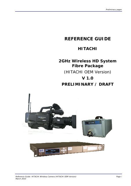
<strong>REFERENCE</strong> <strong>GUIDE</strong><br />
HITACHI<br />
2GHz Wireless HD System<br />
Fibre Package<br />
(HITACHI OEM Version)<br />
V 1.0<br />
PRELIMINARY / DRAFT<br />
Reference Guide: HITACHI Wireless Camera (HITACHI OEM Version)<br />
March 2010<br />
Page i
Preliminary pages<br />
This document and the information contained in it is the property of<br />
Broadcast Microwave Services Inc. and may be the subject of patents<br />
pending and granted. It must not be used for commercial purposes<br />
nor copied, disclosed, reproduced, stored in a retrieval system<br />
or transmitted in any form or by any means (electronic, mechanical,<br />
photocopying, recording or otherwise), whether in whole<br />
or in part, without BMS’s prior written agreement.<br />
© 2009 Broadcast Microwave Services. All rights reserved.<br />
Issue 1 first published in 2010 by:<br />
Broadcast Microwave Services Europe GmbH & Co. KG<br />
Registered Address:<br />
Schwalbacher Straße 12<br />
65321 Heidenrod – Kemel<br />
Germany<br />
Registered Company Number HRA 6230<br />
Reference Guide: HITACHI Wireless Camera (HITACHI OEM Version)<br />
March 2010<br />
Page ii
Preliminary pages<br />
Contents<br />
1 INTRODUCTION 1<br />
1.1 Preliminary remarks ......................................................................... 1<br />
1.2 Designation .................................................................................... 1<br />
1.3 Delivered items ............................................................................... 1<br />
1.4 Application of the HITACHI wireless transmitter .................................. 2<br />
1.4.1 Typical application of the HITACHI fibre system ........................... 2<br />
2 GETTING STARTED 3<br />
2.1 Safety instructions ........................................................................... 3<br />
2.2 Installing the HITACHI wireless camera components ............................ 3<br />
2.3 Connectors ..................................................................................... 3<br />
2.3.1 Antennas................................................................................. 4<br />
2.3.1.1 UHF Antenna 4<br />
2.3.1.2 RF antenna 4<br />
2.3.2 Power supply ........................................................................... 4<br />
2.3.3 Intercom headset ..................................................................... 5<br />
2.3.4 Microphones ............................................................................ 5<br />
2.3.5 RS 232 ................................................................................... 5<br />
3 CONFIGURING THE HITACHI WIRELESS CAMERA DIGITAL TRANSMITTER 5<br />
3.1 Control panel .................................................................................. 5<br />
3.1.1 The LC display ......................................................................... 6<br />
3.1.2 The control buttons................................................................... 6<br />
3.2 Menu structure ................................................................................ 6<br />
3.2.1 Frequency ............................................................................... 8<br />
3.2.2 Software version ...................................................................... 8<br />
3.2.3 Display off ............................................................................... 9<br />
3.2.4 Display brightness ...................................................................10<br />
3.2.5 Data frequency .......................................................................11<br />
3.2.6 Transmission power .................................................................12<br />
3.2.7 Mic Phantom Power..................................................................12<br />
3.2.8 Audio Rear Gain ......................................................................13<br />
3.2.9 Audio Rear Input .....................................................................13<br />
3.2.10 Audio Front Input ....................................................................14<br />
3.2.11 Modulator Setup......................................................................14<br />
3.2.12 Video Setup............................................................................15<br />
4 CONFIGURING THE HITACHI RECEIVE UNITS 15<br />
4.1 Connection of the indoor units ..........................................................15<br />
4.2 Installing the DR2500HD Receiver.....................................................16<br />
Reference Guide: HITACHI Wireless Camera (HITACHI OEM Version)<br />
March 2010<br />
Page iii
Preliminary pages<br />
4.3 Control buttons and Alarm status at the front of the device.................16<br />
4.3.1 The Display ............................................................................16<br />
4.3.2 The control buttons..................................................................16<br />
4.3.3 Alarm and Status.....................................................................16<br />
4.4 Connectors and indicators at the rear of the device..............................17<br />
5 OPERATING THE DR2500ASI DECODER A<br />
5.1 Menu structure ................................................................................ D<br />
5.2 PRESETS ........................................................................................ E<br />
5.3 Frequency assignment...................................................................... F<br />
5.4 Bandwidth selection ......................................................................... G<br />
5.5 Save Preset .....................................................................................I<br />
5.6 Genlock...........................................................................................J<br />
5.7 Main Sreen ..................................................................................... L<br />
5.8 Contrast .........................................................................................M<br />
5.9 Display OFF ....................................................................................M<br />
5.10 Software....................................................................................... N<br />
6 OPERATING THE MODULARX IDU FIBRE N<br />
6.1 ModulaRX IDU Fibre Unit................................................................... N<br />
6.2 Menu structure ................................................................................O<br />
UHF transmitter ..................................................................................... P<br />
6.3 Intermodulation distortion.................................................................Q<br />
6.4 Frequency table for data transmission.................................................Q<br />
7 OPERATING THE FIBRE ODU T<br />
7.1 Menu structure of Fibre IDU .............................................................. T<br />
7.2 Unlock Keyboard.............................................................................. U<br />
7.3 Frequency RX.................................................................................. U<br />
7.4 Frequency TX .................................................................................. U<br />
7.5 Contrast ......................................................................................... U<br />
7.6 Display OFF .................................................................................... V<br />
Reference Guide: HITACHI Wireless Camera (HITACHI OEM Version)<br />
March 2010<br />
Page iv
Preliminary pages<br />
About this Reference Guide<br />
This Reference Guide provides instructions and information for the installation and operation<br />
of the HITACHI wireless transmitter. It is not a comprehensive manual for all<br />
camera functions.<br />
This Reference Guide should be kept in a safe place for reference for the life of the<br />
equipment. It is not intended that this Reference Guide will be amended by the issue<br />
of individual pages. Any revision will be by a complete reissue. If passing the equipment<br />
to a third party, please also pass on the relevant documentation.<br />
Issues of this Reference Guide are listed below:<br />
Issue Date Build Version Comments<br />
1 March 2010 1.0 Draft<br />
Reference Guide: HITACHI Wireless Camera (HITACHI OEM Version)<br />
March 2010<br />
Page v
Preliminary pages<br />
Warnings, Cautions and Notes<br />
Heed Warnings<br />
All warnings on the product and in the operating instructions should be adhered to.<br />
The manufacturer can not be held responsible for injuries or damage where warnings<br />
and cautions have been ignored or taken lightly.<br />
Read Instructions<br />
All the safety and operating instructions should be read before this product is operated.<br />
Follow Instructions<br />
All operating and use instructions should be followed.<br />
Retain Instructions<br />
The safety and operating instructions should be retained for future reference.<br />
Warning<br />
Warnings give information which, if strictly observed, will prevent personal<br />
injury or death, OR DAMAGE TO PERSONAL PROPERTY OR THE ENVIRON-<br />
MENT. They are boxed and shaded for emphasis, as in this example, and<br />
are placed immediately preceding the point at which the reader requires<br />
them.<br />
Cautions<br />
Cautions give information which, if strictly followed, will prevent damage to equipment<br />
or other goods. They are boxed for emphasis, as in this example, and are<br />
placed immediately preceding the point at which the reader requires them.<br />
Notes<br />
Notes provide supplementary information. They are highlighted for emphasis, as in<br />
this example, and are placed immediately after the relevant text.<br />
Reference Guide: HITACHI Wireless Camera (HITACHI OEM Version)<br />
March 2010<br />
Page vi
Chapter 1: Introduction<br />
Contact Information<br />
BMS Customer Services<br />
Support Services<br />
Warranty<br />
Our primary objective is to provide first class customer care that is tailored<br />
to your specific business and operational requirements. All levels are supported<br />
by one or more service performance reviews to ensure the perfect<br />
partnership between Broadcast Microwave Services and your business.<br />
All BMS Products and Systems are designed and built to the highest standards<br />
and are covered under a comprehensive 12 month warranty.<br />
Levels of Continuing BMS Service Support<br />
For stand-alone equipment, then Broadcast Microwave Services BASIC<br />
Advantage is the value for money choice for you. BASIC provides you<br />
with year-by-year Service long after the warranty has expired.<br />
For systems support you can choose either GOLD or SILVER Advantage.<br />
These packages are designed to save you costs and protect your income<br />
through enlisting the help of BMS support specialists.<br />
VOYAGER Advantage is the truly mobile service solution. This provides a<br />
package specifically designed to keep you mobile and operational.<br />
Call BMS Sales for more details.<br />
Where to Find Us<br />
Europe: Tel: + 49-6124-7239-0<br />
Fax: + 49-6124-7239-29<br />
saleseurope@bms-inc.com<br />
<strong>America</strong>s: Tel: +1-858-391-3050<br />
Fax: +1-858-391-3049<br />
sales@bms-inc.com<br />
Internet Address:<br />
http://www.bms-inc.com<br />
Reference Guide: HITACHI Wireless Camera (HITACHI OEM Version) Page 1<br />
March 2010
Chapter 1: Introduction<br />
Technical Training<br />
Training Courses<br />
Where to Find Us<br />
BMS provides a wide range of training courses on the operation and maintenance<br />
of our products and on their supporting technologies. BMS can<br />
provide both regularly scheduled courses and training tailored to individual<br />
needs. Courses can be run either at your premises or at one of our dedicated<br />
training facilities.<br />
For further information on BMS training programme please contact us:<br />
International Telephone: + 49-6124-7239-0 (Europe)<br />
+1-858-391-3050 (<strong>America</strong>)<br />
International Facsimile:<br />
E-mail Address:<br />
+ 49-6124-7239-29 (Europe)<br />
+1-858-391-3050 (<strong>America</strong>)<br />
saleseurope@bms-inc.com (Europe)<br />
sales@bms-inc.com (<strong>America</strong>)<br />
Internet Address:<br />
http://www.bms-inc.com<br />
Customer Services and Technical Training Postal Address<br />
Broadcast Microwave Services Europe GmbH + Co. KG<br />
Schwalbacher Straße 12<br />
65321 Heidenrod–Kemel<br />
Germany<br />
Return of Equipment<br />
If you need to return equipment for repair, please contact<br />
Tel: + 49 6124 7239-0<br />
Fax: + 49 6124 7239-29<br />
E-mail: saleseurope@bms-inc.com<br />
Address: see above.<br />
Technical Publications<br />
If you need to contact Broadcast Microwave Services Europe regarding this<br />
publication please e-mail to saleseurope@bms-inc.com<br />
Reference Guide: HITACHI Wireless Camera (HITACHI OEM Version) Page 2<br />
March 2010
Chapter 1: Introduction<br />
1 Introduction<br />
1.1 Preliminary remarks<br />
The present document, "Reference Guide, HITACHI Wireless Camera (HITACHI OEM<br />
Version)”, is intended to be used for the proper set-up and operation of the wireless<br />
transmitter unit of the HITACHI camera system.<br />
Designation<br />
Manufacturer:<br />
1.2 Designation<br />
HITACHI 2GHz Wireless HD System Fibre Package<br />
(HITACHI OEM Version)<br />
Broadcast Microwave Services Europe GmbH + Co. KG<br />
1.3 Delivered items<br />
1 x DR2420ODU-Fibre (P/N 12.1617.000)<br />
1 x ModulaRX IDU Fibre (P/N 12.1620.000)<br />
1 x OEM;CW-HD1000 (P/N 11.2501.000)<br />
Reference Guide: HITACHI Wireless Camera (HITACHI OEM Version) Page 1<br />
March 2010
Chapter 1: Introduction<br />
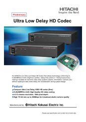
1.4 Application of the HITACHI wireless transmitter<br />
1.4.1 Typical application of the HITACHI fibre system<br />
Data TX (UHF<br />
455 MHz)<br />
500mW<br />
Data RX<br />
2.3GHz<br />
HD-SDI/Audio/Data<br />
Tally<br />
230VAC<br />
2x Audio<br />
Genlock<br />
HD-SDI<br />
Figure 1: Typical Application<br />
Reference Guide: HITACHI Wireless Camera (HITACHI OEM Version) Page 2<br />
March 2010
Chapter 3: Operating the equipment<br />
2 Getting started<br />
2.1 Safety instructions<br />
Warning<br />
The regulations of VDE0100 must be observed for installation and operation<br />
of the unit.<br />
Caution<br />
• Before powering up the camera for the first time make sure all connections are<br />
completed.<br />
• Pay attention to all warnings in this document.<br />
• Make sure that the ventilation openings of the camera are not obstructed to ensure<br />
efficient heat dissipation.<br />
• The camera should be protected against moisture and humidity.<br />
2.2 Installing the HITACHI wireless camera components<br />
The wireless transmitter of the HITACHI camera is integrated into the camera housing.<br />
2.3 Connectors<br />
Please make sure you connect all antennas and cables to the below described connector<br />
jacks.<br />
Reference Guide: HITACHI Wireless Camera (HITACHI OEM Version) Page 3<br />
March 2010
Chapter 3: Operating the equipment<br />
2.3.1 Antennas<br />
Figure 2: Antenna Sockets<br />
2.3.1.1 UHF Antenna<br />
Socket number 1 in Figure 2 is the UHF input for the intercom connection. To this<br />
socket a 50-Ohm UHF antenna must be mounted.<br />
2.3.1.2 RF antenna<br />
Connect an active RF antenna to socket number 2 in Figure 2. You may need to apply<br />
an N-N adaptor. The impedance is 50 Ohm.<br />
Caution<br />
If you wish to connect other than the specified components (eg power amplifier or<br />
passive antennas) a DC blocker must be applied. Otherwise, your HITACHI Wireless<br />
Camera and/or other connected equipment may be damaged.<br />
Note<br />
The HF output supplies 5 VDC for an active antenna.<br />
2.3.2 Power supply<br />
Most likely, your camera will be fed by a rechargeable battery. A V-mount bracket on<br />
the back side of the camera supports the battery housing.<br />
Reference Guide: HITACHI Wireless Camera (HITACHI OEM Version) Page 4<br />
March 2010
Chapter 3: Operating the equipment<br />
If you desire to use an external power supply, you will find a 4-pole XLR 12 VDC input<br />
on the back side of the camera. As When connected to an external power supply the<br />
camera will switch from battery operation to the external power supply.<br />
2.3.3 Intercom headset<br />
Connect the intercom headset to the 5-pole XLR socket on the back side of you camera.<br />
2.3.4 Microphones<br />
The HITACHI Wireless Camera is equipped with two microphone input sockets on the<br />
back side. Connect your external microphones to these 3-pole XLR connectors.<br />
2.3.5 RS 232<br />
For servicing (eg software updates of the control panel) the wireless transmitter unit<br />
of the camera you may need to connect a PC to the RS 232 socket found below the<br />
control panel.<br />
3 Configuring the HITACHI wireless camera digital transmitter<br />
3.1 Control panel<br />
The digital transmitter unit of your HITACHI wireless camera is equipped with a control<br />
panel including control buttons and an LC display.<br />
Figure 3: Transmitter Unit Control Panel<br />
The control panel allows you to easily adjust the settings of the digital transmitter unit<br />
of your HITACHI Wireless Camera.<br />
Reference Guide: HITACHI Wireless Camera (HITACHI OEM Version) Page 5<br />
March 2010
Chapter 3: Operating the equipment<br />
Note<br />
While configuring the digital transmitter you must not disconnect the power supply<br />
from the camera. This may cause loss of presets.<br />
3.1.1 The LC display<br />
The HITACHI Wireless Camera digital transmitter unit is equipped with an LC display.<br />
This display simplifies the configuration.<br />
T.<br />
MHz<br />
Figure 4: LC Display<br />
Unless you are adjusting your transmitter parameters, the display shows the signal<br />
strength of the received camera control UHF signal in the upper left corner, an error<br />
code in the upper right corner and the adjusted transmitting frequency of the video<br />
and audio signal.<br />
3.1.2 The control buttons<br />
The control buttons are located below the LC display on the control panel. These buttons<br />
are used for the navigation through the different menu items. Depending on the<br />
parameter to be changed the operator can use the control buttons “Up”/”Down”<br />
and/or “Left”/”Right”.<br />
Figure 5: Control Buttons<br />
3.2 Menu structure<br />
After you switched on the HITACHI Wireless Camera the control panel of the digital<br />
transmitter unit shows an initialisation message. Once the initialisation phase has finished<br />
the main display (see Figure 4) is shown. Now you can access to the menu and<br />
adjust the different settings.<br />
Reference Guide: HITACHI Wireless Camera (HITACHI OEM Version) Page 6<br />
March 2010
Chapter 3: Operating the equipment<br />
T.<br />
6500 2328.000 MHz<br />
MHz<br />
Figure 6: Menu Structure<br />
Reference Guide: HITACHI Wireless Camera (HITACHI OEM Version) Page 7<br />
March 2010
Chapter 3: Operating the equipment<br />
3.2.1 Frequency<br />
On the main display, press the button “OK” for approximately 3 seconds. The current<br />
frequency is shown.<br />
FREQUENCY<br />
MHz<br />
Figure 7: Frequency Menu<br />
After pressing “OK” another time for approximately 3 seconds the first digit of the frequency<br />
is highlighted and the display looks like shown in Figure 8. Press the “UP” control<br />
button to increase the value or the “DOWN” control button to decrease. To move<br />
to the next digit press the “RIGHT” control button or press the “LEFT” control button<br />
to jump back to the previous digit. Now adjust the frequency you wish to use.<br />
FREQUENCY<br />
Figure 8: Adjusting the Frequency<br />
To confirm the selected frequency press the “OK” button and the main menu will be<br />
shown.<br />
3.2.2 Software version<br />
The control panel gives you the opportunity to show the recently installed software<br />
version. On the main display, press again the button “OK” for approximately 3 seconds.<br />
The current frequency is shown. Now use the “UP”/”DOWN” buttons to go to the<br />
“SOFTWARE” menu.<br />
No further adjustments can be made. The LC display shows the software version.<br />
Reference Guide: HITACHI Wireless Camera (HITACHI OEM Version) Page 8<br />
March 2010
Chapter 3: Operating the equipment<br />
SOFTWARE<br />
Figure 9: Software Version Display<br />
3.2.3 Display off<br />
In certain production environments you may want to switch the LC display off.<br />
On the main display, press the button “OK” for approximately 3 seconds. The current<br />
frequency is shown. Now use the “UP”/”DOWN” buttons to go to the “DISPLAY OFF”<br />
menu.<br />
DISPLAY OFF<br />
Figure 10: Display Off Menu<br />
Press the “OK” button again for approximately 3 seconds and the current display-off<br />
time level is highlighted. Use the “UP”/”DOWN” buttons in order to increase or decrease<br />
the display brightness in a range from 0 to 240 seconds in steps of 15 seconds.<br />
This is the time your display switches off after no button was pressed on the control<br />
panel. If you adjust the value to 0 seconds the display remains switched on.<br />
DISPLAY OFF<br />
Figure 11: Display-off Time Adjustment<br />
To confirm the selected display-off time press the “OK” button and the main menu will<br />
be shown.<br />
Note<br />
Once the display is switched off simply by pressing the “OK” button for<br />
Reference Guide: HITACHI Wireless Camera (HITACHI OEM Version) Page 9<br />
March 2010
Chapter 3: Operating the equipment<br />
approximately 3 seconds it switches on again and you can use the menu. After the<br />
previously adjusted time without any action the display automatically switches off<br />
again.<br />
3.2.4 Display brightness<br />
You may wish to adjust the brightness of the LC display to your production environment.<br />
On the main display, press the button “OK” for approximately 3 seconds. The current<br />
frequency is shown. Now use the “UP”/”DOWN” buttons to go to the “CONTRAST”<br />
menu.<br />
CONTRAST<br />
Figure 12: Contrast Menu<br />
Press the “OK” button again for approximately 3 seconds and the current contrast<br />
level is highlighted. Use the “UP”/”DOWN” buttons in order to increase or decrease the<br />
display brightness in a range from 0 to 15. 0 is the darkest adjustment, 15 the highest<br />
brightness.<br />
CONTRAST<br />
Figure 13: Display Brightness Adjustment<br />
Reference Guide: HITACHI Wireless Camera (HITACHI OEM Version) Page 10<br />
March 2010
Chapter 3: Operating the equipment<br />
To confirm the selected brightness level press the “OK” button and the main menu will<br />
be shown.<br />
3.2.5 Data frequency<br />
The camera may be connected to a CCU via an UHF wireless connection. In the “DATA<br />
FREQUENCY” menu you have the possibility to adjust the frequency of the channel.<br />
On the main display, press the button “OK” for approximately 3 seconds. The current<br />
frequency is shown. Now use the “UP”/”DOWN” buttons to go to the “DATA FRE-<br />
QUENCY” menu.<br />
DATA FREQUENCY<br />
Figure 14: Data Frequency Menu<br />
After pressing “OK” another time for approximately 3 seconds the data frequency is<br />
shown red. Use the control buttons to adjust the frequency in steps of 0.01 MHz.<br />
DATA FREQUENCY<br />
Figure 15: Adjusting the Data Frequency<br />
To confirm the selected frequency press the “OK” button and the main menu will be<br />
shown.<br />
Reference Guide: HITACHI Wireless Camera (HITACHI OEM Version) Page 11<br />
March 2010
Chapter 3: Operating the equipment<br />
3.2.6 Transmission power<br />
In order to trim the transmission power to your environment you can choose between<br />
three preset power levels in the “OUTPUT POWER” menu.<br />
On the main display, press the button “OK” for approximately 3 seconds. The current<br />
frequency is shown. Now use the “UP”/”DOWN” buttons to go to the “OUTPUT POWER”<br />
menu.<br />
OUTPUT POWER<br />
Figure 16: Output Power Menu<br />
Press the “OK” button again for approximately 3 seconds and the current output<br />
power level is highlighted. With the “UP”/”DOWN” control buttons you can choose between<br />
low, medium and high transmission power.<br />
OUTPUT POWER<br />
MEDIUM<br />
LOW<br />
Figure 17: Output Power Adjustment<br />
(Low=10mW; Medium=100mW; High=400mW).To confirm the selected power level<br />
press the “OK” button and the main menu will be shown.<br />
3.2.7 Mic Phantom Power<br />
The control panel gives you the opportunity to enable the MIC phantom power if “MIC”<br />
is selected in the menu “AUDIO REAR INPUT”.<br />
MIC PHANTOM POWER<br />
Figure 13: Software Version Display<br />
Reference Guide: HITACHI Wireless Camera (HITACHI OEM Version) Page 12<br />
March 2010
3.2.8 Audio Rear Gain<br />
If you connect an audio signal to the “Rear Audio” connector at the back of the camera,<br />
then you can adjust the gain of the signal. In order to adjust the audio gain you<br />
can choose between the values +30….-10dB in the “AUDIO REAR GAIN” menu.<br />
On the main display, press the button “OK” for approximately 3 seconds. The current<br />
frequency is shown. Now use the “UP”/”DOWN” buttons to go to the “AUDIO REAR<br />
GAIN” menu.<br />
AUDIO REAR GAIN<br />
Figure 14: Audio Rear Gain<br />
Press the “OK” button again for approximately 3 seconds and the current gain level is<br />
highlighted. With the “UP”/”DOWN” control buttons you can choose between the values<br />
+30….-10dB.<br />
3.2.9 Audio Rear Input<br />
In order to select the audio input you can choose between “LINE” and “MIC”<br />
On the main display, press the button “OK” for approximately 3 seconds. The current<br />
frequency is shown. Now use the “UP”/”DOWN” buttons to go to the “AUDIO REAR IN-<br />
PUT”” menu.<br />
AUDIO REAR INPUT<br />
Figure 15: Audio Rear Input<br />
Press the “OK” button again for approximately 3 seconds and the current input is<br />
highlighted. With the “UP”/”DOWN” control buttons you can choose between “MIC”<br />
and “LINE”.<br />
Reference Guide: HITACHI Wireless Camera (HITACHI OEM Version) Page 13<br />
March 2010
Note<br />
If you select “LINE” you will not see the “MIC PHANTOM POWER” sub menu<br />
3.2.10 Audio Front Input<br />
Having VF SETUP selected in this sub menu you will be able to adjust the audio of the<br />
front microfone through the viewfinder menu.<br />
AUDIO FRONT INPUT<br />
Figure 16: Audio Front Input<br />
3.2.11 Modulator Setup<br />
This setup shows you the current modulation of the transmitter. It is not possible to<br />
change something.<br />
MODULATOR SETUP<br />
FEC 2/3<br />
GUARD 1/32<br />
Figure 17: Modulator Setup<br />
Reference Guide: HITACHI Wireless Camera (HITACHI OEM Version) Page 14<br />
March 2010
1<br />
2<br />
3<br />
4<br />
5<br />
6<br />
7<br />
8<br />
9<br />
3.2.12 Video Setup<br />
This setup shows you the current video parameters. It is not possible to change something.<br />
VIDEO SETUP<br />
29,97 fps<br />
Figure 17: Modulator Setup<br />
4 Configuring the HITACHI Receive units<br />
4.1 Connection of the indoor units<br />
In the figure 18 you can see how to connect the devices with the delivered cables.<br />
17.1165.401<br />
Figure 18: How to connect the cables to the devices<br />
Reference Guide: HITACHI Wireless Camera (HITACHI OEM Version) Page 15<br />
March 2010
4.2 Installing the DR2500HD Receiver<br />
The DR2505-ASI decoder can be accommodated in a 19" rack with a height of 1 RU.<br />
4.3 Control buttons and Alarm status at the front of the<br />
device<br />
4.3.1 The Display<br />
A LC display is used to show the RF and COFDM parameters and the configuration parameters.<br />
1:<br />
2:<br />
Status: Unlocked<br />
Const: --<br />
MER/dB<br />
00<br />
00<br />
FEC: -- Guard: --<br />
DR2500-ASI<br />
01<br />
2349.00MHz<br />
Figure Figure 1 : 19: LCD LCD Display<br />
4.3.2 The control buttons<br />
The control buttons are located on the right side of the front panel. They allow navigation<br />
of the different receiver DR2500HD menus. Depending on the parameter to be<br />
changed the operator can use the control buttons “UP”/”Down” and/or “Left”/”Right”<br />
OK<br />
Figure 2 Figure : Control 20: buttons Control buttons<br />
4.3.3 Alarm and Status<br />
Lights up, when the tuned Frequency differs from the allowed Frequency range of the<br />
receiver (Fibre-ODU). The DR2500-ASI switches automatically to the next highest or<br />
lowest adjustable Frequency.<br />
Lights up, when the DR2500ASI doesn’t receive any signals (Unlocked). Once a signal<br />
is received, the light switches off.<br />
Reference Guide: HITACHI Wireless Camera (HITACHI OEM Version) Page 16<br />
March 2010
Lights up, when the DR2500-ASI is powered by the power supply.<br />
4.4 Connectors and indicators at the rear of the device<br />
ASI in<br />
Genlock L Audio R<br />
µPC/Data 12VDC AUX<br />
HD-SDI<br />
HD-SDI<br />
Figure 321: : Rear Rear of the of DR2500ASI the DR2500HD Diversity Receiver<br />
At the rear of the DR2500HD Diversity Receiver:<br />
• 1 X “ASI in”, this is the ASI signal which comes from the Fibre-IDU<br />
• 1 X “Genlock in” for Synchronization [SD- or HD-SDI], BNC female<br />
• 2 X “SDI out” for video, BNC female<br />
• 1 X "12-18V-DC" 4-pol XLR connector for 12-18V DC power supply<br />
• “Ant.1” and “Ant.2”are 2 X SMA (f) sockets for RF input<br />
• 1 X “uPC/Data” is a Serial 9 pin Sub-D (f) socket for remote control RX and data<br />
output<br />
• “Audio L” and “Audio R” are 3-pol XLR connector for audio out<br />
Caution<br />
Be sure that the ventilation openings are not obstructed.<br />
Reference Guide: HITACHI Wireless Camera (HITACHI OEM Version) Page 17<br />
March 2010
5 Operating the DR2500ASI decoder<br />
When the DR2500ASI is connected to a power supply, the display at the front of the<br />
unit will light up.<br />
During the initialisation phase, the company’s name, receiver’s name as well as the<br />
software version are displayed.<br />
The operation of the unit is controlled using the control elements located at the front<br />
panel.<br />
BMS inc<br />
DR2500-ASI<br />
v2.04<br />
Figure 4 : Initialisation phase<br />
Figure 22: Initalisation phase<br />
After that the initialisation phase is done the receiver switches automatically to the<br />
“Main Display” see Figure 6.<br />
1:<br />
2:<br />
Status: Locked<br />
Const: 64QAM<br />
MER/dB<br />
22<br />
24<br />
DR2524-HD<br />
01<br />
2349.00MHz<br />
GL (AUTO)<br />
FEC: 2/3 Guard: 1/32<br />
Figure Figure 5 : 23: Main display Display<br />
In case that there is good transmission at the set frequency, you will get the overview<br />
displayed like in the Picture shown in “Figure 6”<br />
On top of the right side you can see the model name of the receiver and under the<br />
model name are displayed the selected preset and the frequency which is stored in<br />
that preset.<br />
On the left side the bar graph for the MER value is shown. In “Figure 6” the bar graph<br />
value would be 0 in case of bad reception, because no transmission is received at the<br />
moment by the receiver. Bar graph “1:” shows the MER from antenna 1 and “2:”<br />
shows the value from antenna 2.<br />
Reference Guide: HITACHI Wireless Camera (HITACHI OEM Version)<br />
March 2010<br />
Page A
Note<br />
The modulation error ratio (MER) is a measure of the SNR in a digitally modulated<br />
signal. Like SNR, MER can be expressed in dB.<br />
Signal-to-noise (SNR or S/N) is an electrical engineering measurement, defined as<br />
the ratio of a signal power to the noise power corrupting the signal. Signal-tonoise<br />
ratio compares the level of a desired signal to the level of background noise.<br />
The higher the ratio, the less obtrusive the background noise is.<br />
• Status: Unlocked : will be displayed when any signal is received<br />
Locked : will be displayed when a signal is received<br />
At the bottom of the display the Constellation, FEC and Guard Interval will be shown<br />
automatically, if a signal is received and decoded by the receiver.<br />
• Guard: 1/4, 1/8, 1/16, 1/32 can be displayed depending on the bandwidth of<br />
the transmitted signal<br />
In COFDM, the beginning of each symbol is preceded by a guard interval. As long as the<br />
echoes fall within this interval, they will not affect the receiver's ability to safely decode the<br />
actual data, as data is only interpreted outside the guard interval.<br />
Longer guard periods allow more distant echoes to be tolerated. However, longer guard<br />
intervals reduce the channel efficiency. In DVB-T, four guard intervals are available (given<br />
as fractions of a symbol period): 1/32 ; 1/16 ; 1/8 ; 1/4<br />
Hence, 1/32 gives lowest protection and the highest data rate. 1/4 results in the best<br />
protection but the lowest data rate<br />
• FEC: 1/2, 2/3, 3/4, 5/6 can be displayed depending on the FEC of the transmitted<br />
signal<br />
Forward Error Correction (FEC) is a system of error control for data transmission, whereby<br />
the sender adds redundant data to its messages, also known as an error-correction code.<br />
This allows the receiver to detect and correct errors (within some bound) The advantage of<br />
forward error correction is that a back-channel is not required, at the cost of higher bandwidth<br />
requirements on average.<br />
Reference Guide: HITACHI Wireless Camera (HITACHI OEM Version)<br />
March 2010<br />
Page B
• Const: QPSK, 16 QAM, 64 QAM can be displayed depending on the modulation<br />
mode of the transmitted signal<br />
Constellation (DVB-T Modulation) mode can be between QPSK, 16QAM and 64QAM.<br />
QPSK is the default mode (in SD transmission) and will give the strongest most rugged RF<br />
link performance. Selecting 16QAM reduces the link performance by 5dB but improves the<br />
link data throughput, giving significantly better video quality. 64QAM is the constellation<br />
mode for HD transmission due to the high data rate.<br />
Reference Guide: HITACHI Wireless Camera (HITACHI OEM Version)<br />
March 2010<br />
Page C
5.1 Menu structure<br />
MER/dB<br />
1:<br />
2:<br />
Status: Locked<br />
Const: 64QAM<br />
22<br />
24<br />
GL (AUTO)<br />
FEC: 2/3 Guard: 1/32<br />
DR2524-HD<br />
01<br />
2349.00MHz<br />
Main Screen<br />
PRESET<br />
PRESET 1…...PRESET26<br />
FREQUENCY<br />
Transmission frequency set<br />
BANDWIDTH<br />
6MHz / 7MHz / 8MHz<br />
SAVE PRESET<br />
YES / NO<br />
GENLOCK<br />
OFF / AUTO / ON<br />
Main Screen<br />
FREQUENCY / MER in dB<br />
CONTRAST<br />
000...127<br />
DISPLAY OFF<br />
000...240 seconds<br />
SOFTWARE<br />
Software Version<br />
Reference Guide: HITACHI Wireless Camera (HITACHI OEM Version)<br />
March 2010<br />
Page D
5.2 PRESETS<br />
Press the button “OK” for 2-3 seconds to enter the main menu.<br />
The first submenu is the “PRESET”-menu, where it is possible to select 26 different<br />
presets. Each preset can contain a different frequency which the customer can assign<br />
due to his needs.<br />
PRESET<br />
01<br />
2349.00MHz<br />
DR2500-ASI<br />
To change the preset number press again the button “OK” for 2-3 seconds to be able<br />
to change the preset. Two small triangle will show that the change mode is activated.<br />
PRESET<br />
01<br />
2349.00MHz<br />
DR2500-ASI<br />
Now it is possible to select with the UP/DOWN button 1 of 26 presets. To confirm the<br />
selected preset press the “OK” button and after that it will appear “UPDATING DE-<br />
VICE”.<br />
PRESET<br />
26<br />
UPDATING DEVICE<br />
DR2500-ASI<br />
Note<br />
A quick button press will return you to the previous menu to effect and save the<br />
changes and another quick press takes you away from the main menu<br />
Reference Guide: HITACHI Wireless Camera (HITACHI OEM Version)<br />
March 2010<br />
Page E
5.3 Frequency assignment<br />
Press the button “OK” for 2-3 seconds to enter in the main menu and one time the<br />
right button for the frequency option. This menu gives the user the possibility to set<br />
the frequency manually without using the preset option.<br />
FREQUENCY<br />
2385.00MHZ<br />
DR2500-ASI<br />
Press again the button “OK” for 2-3 seconds to be able to change the frequency<br />
range. After pressing “OK” for the second time the first digit is highlighted and the<br />
display looks like in figure 7. Press the “UP” control button to increase the digit and<br />
the “DOWN” to decrease, to move to the second digit press the “RIGHT” control button<br />
or Press the “LEFT” to come back to the previous digit.<br />
FREQUENCY<br />
2385.00MHZ<br />
DR2500-ASI<br />
To confirm the frequency press the “OK” button and after that it will appear “UPDAT-<br />
ING DEVICE”.<br />
FREQUENCY<br />
2385.00MHZ<br />
UPDATING DEVICE<br />
DR2500-ASI<br />
Reference Guide: HITACHI Wireless Camera (HITACHI OEM Version)<br />
March 2010<br />
Page F
Note<br />
A quick button press will return you to the previous menu to effect and save the<br />
changes and another quick press takes you away from the main menu<br />
1:<br />
2:<br />
Status: Locked<br />
Const: 64QAM<br />
MER/dB<br />
22<br />
24<br />
DR2500-ASI<br />
**<br />
2388.00MHz<br />
GL (AUTO)<br />
FEC: 2/3 Guard: 1/32<br />
At the position where normally the preset number is shown, there are displayed two<br />
stars “**”, which is an indication for the user, that no preset is set, but a manually<br />
frequency.<br />
5.4 Bandwidth selection<br />
Press the button “OK” for 2-3 seconds to enter the main menu.<br />
The third submenu is the “BANDWIDTH”-menu, where it is possible to select 3 different<br />
bandwidth (6 / 7 / or 8 MHz). Before changing the bandwidth, please check the<br />
bandwidth setting of your transmitter.<br />
BANDWIDTH<br />
8 MHz<br />
DR2500-ASI<br />
Note<br />
For HD transmission you have to set the bandwidth to 8 MHz.<br />
Reference Guide: HITACHI Wireless Camera (HITACHI OEM Version)<br />
March 2010<br />
Page G
To change the bandwidth press again the button “OK” for 2-3 seconds to be able to<br />
change the setting. Two small triangle will show that the change mode is activated.<br />
BANDWIDTH<br />
8 MHz<br />
DR2500-ASI<br />
Now it is possible to select with the UP/DOWN button the bandwidth of the transmitted<br />
signal you want to receive. To confirm the selected preset press the “OK” button<br />
and after that it will appear “UPDATING DEVICE”.<br />
BANDWIDTH<br />
8 MHz<br />
UPDATING DEVICE<br />
DR2524-HD<br />
Note<br />
A quick button press will return you to the previous menu to effect and save the<br />
changes and another quick press takes you away from the main menu<br />
Reference Guide: HITACHI Wireless Camera (HITACHI OEM Version)<br />
March 2010<br />
Page H
5.5 Save Preset<br />
If a frequency has been set in the “Frequency” option, described in Chapter 3.3, it is<br />
possible to save this frequency in one of the 26 Preset options. To save a frequency in<br />
a Preset, follow the steps:<br />
1. Select the Preset you want to store the new frequency (Chapter 3.2)<br />
2. Set the new frequency (Chapter 3.3)<br />
3. Save preset:<br />
Press the button “OK” for 2-3 seconds to enter in the main menu and two times<br />
the right button for the “SAVE PRESET” option.<br />
SAVE PRESET<br />
?<br />
DR2524-HD<br />
Reference Guide: HITACHI Wireless Camera (HITACHI OEM Version)<br />
March 2010<br />
Page I
This menu gives the user the possibility to save a frequency under the current preset.<br />
Now press again the button “OK” for 2-3 seconds and you will have the choice between<br />
“YES” (to save frequency to current preset) and press the OK button.<br />
SAVE PRESET<br />
YES<br />
DR2524-HD<br />
Now the frequency is stored to the preset.<br />
5.6 Genlock<br />
If a genlock is used with the DR2500HD receiver, the user will have some options to<br />
set the genlock function.<br />
Press the button “OK” for 2-3 seconds to enter in the main menu and three times the<br />
right button for the “GENLOCK” option and press again the “OK” button for 2-3 seconds.<br />
Press the “UP” or “DOWN” control button to select one of the three options<br />
which are given to the user in this menu: OFF / AUTO / ON<br />
1) OFF – the receiver will not use any external genlock<br />
1:<br />
2:<br />
Status: Locked<br />
Const: 64QAM<br />
MER/dB<br />
22<br />
24<br />
FEC: 2/3 Guard: 1/32<br />
DR2524-HD<br />
**<br />
2388.00MHz<br />
Reference Guide: HITACHI Wireless Camera (HITACHI OEM Version)<br />
March 2010<br />
Page J
2) ON - the receiver will use the external genlock<br />
1:<br />
2:<br />
Status: Locked<br />
Const: 64QAM<br />
MER/dB<br />
22<br />
24<br />
DR2524-HD<br />
**<br />
2388.00MHz<br />
GL<br />
FEC: 2/3 Guard: 1/32<br />
GL=Genlock „ON“<br />
Note<br />
If Genlock “ON” is selected but no Genlock signal is present, the decoder will not<br />
be able to decode any signal<br />
3) AUTO – the receiver will detect automatically if an external genlock is connected<br />
1:<br />
2:<br />
Status: Locked<br />
Const: 64QAM<br />
MER/dB<br />
22<br />
24<br />
DR2524-HD<br />
**<br />
2388.00MHz<br />
GL (AUTO)<br />
FEC: 2/3 Guard: 1/32<br />
GL=Genlock „AUTO“<br />
Now press again the button “OK” for 2-3 seconds to confirm your choice.<br />
Reference Guide: HITACHI Wireless Camera (HITACHI OEM Version)<br />
March 2010<br />
Page K
5.7 Main Sreen<br />
It is possible to choose between two Main Screens. Press the button “OK” for 2-3 seconds<br />
to enter in the main menu and four times the right button for the “Main Screen”<br />
option and press again the “OK” button for 2-3 seconds. Press the “UP” or “DOWN”<br />
control button to select one of the two options: Frequency or MER in dB.<br />
1) Main Screen (FREQUENCY)<br />
FREQUENCY<br />
2385.00MHZ<br />
DR2524-HD<br />
In this display you will get only the frequency displayed and the device model.<br />
2) Main Screen (MER in dB)<br />
1:<br />
2:<br />
Status: Locked<br />
Const: 64QAM<br />
MER/dB<br />
22<br />
24<br />
DR2524-HD<br />
01<br />
2349.00MHz<br />
GL (AUTO)<br />
FEC: 2/3 Guard: 1/32<br />
The display shows you different information at the same time:<br />
- MER/dB for antenna1 and antenna 2<br />
- Status of incoming signal (locked or unlocked)<br />
- Modulation of received and decoded Signal (QPSK/16QAM/64QAM)<br />
- FEC (1/2;2/3;4/4;5/6;7/8)<br />
- Guard interval (1/4;1/8;1/16;1/32)<br />
- Genlock setting ( - [Genlock OFF]; GL [Genlock ON]; GL (AUTO); [Genlock<br />
AUTO])<br />
- Preset number and frequency (if preset is selected) or only frequency if no preset<br />
is selected<br />
Reference Guide: HITACHI Wireless Camera (HITACHI OEM Version)<br />
March 2010<br />
Page L
5.8 Contrast<br />
Press the button “OK” for 2-3 seconds to enter in the main menu, and then press<br />
twice the control button “RIGHT” to select the sub menu “CONTRAST”.<br />
Press again the button “OK” for 2-3 seconds and then press the control button “UP” or<br />
“DOWN” to choose between a range from 000 to 127. The higher the digit the brighter<br />
the display.<br />
CONTRAST<br />
010<br />
DR2524-HD<br />
Note<br />
A quick button press short will return you to the previous menu and save the<br />
changes. A quick button press exits the main menu<br />
5.9 Display OFF<br />
Press the button “OK” for 2-3 seconds to enter in the main menu, then press three<br />
times the control button “RIGHT” to select the sub menu “DISPLAY OFF”.<br />
Press again the button “OK” for 2-3 seconds and then press the control button “UP” or<br />
“DOWN” to choose between 000s to 240s. The user can choose the time after which<br />
the unit would automatically switch off the display.<br />
Display OFF<br />
000<br />
DR2524-HD<br />
Reference Guide: HITACHI Wireless Camera (HITACHI OEM Version)<br />
March 2010<br />
Page M
Note<br />
A quick button press will return you to the previous menu and save the changes<br />
Another quick press exits the main menu.<br />
5.10 Software<br />
Press the button “OK” for 2-3 seconds to enter in the main menu, then press four<br />
times control button “RIGHT” control button to navigate in the main menu and select<br />
the “SOFTWARE”.<br />
The software version will be displayed.<br />
SOFTWARE<br />
V2.04<br />
DR2524-HD<br />
Note<br />
A quick press returns you to the main menu<br />
6 Operating the ModulaRX IDU Fibre<br />
6.1 ModulaRX IDU Fibre Unit<br />
IDU RX<br />
RCP: OK<br />
CAM: OK<br />
DATA-TX:<br />
DATA-RX:<br />
DataTX<br />
465.53MHz/CH129<br />
UHF-DATA: OK<br />
COFDM-DATA:OK<br />
Reference Guide: HITACHI Wireless Camera (HITACHI OEM Version)<br />
March 2010<br />
Page N
6.2 Menu structure<br />
IDU RX<br />
RCP: OK<br />
CAM: OK<br />
DATA-TX:<br />
DATA-RX:<br />
DataTX<br />
465.53MHz/CH129<br />
UHF-DATA: OK<br />
COFDM-DATA:OK<br />
Main Screen<br />
DATA-FREQUENCY<br />
MAIN SCREEN<br />
CONTRAST<br />
DISPLAY OFF<br />
SOFTWARE<br />
Alarm and Status<br />
The following chapter describes the meaning of the different status of the unit.<br />
DataTX<br />
Shows the current frequency from the data transmitter which is inbuilt into the outdoor<br />
unit.<br />
COFDM o.k.<br />
“OK” lights up, when the transmission between the camera transmitter and the Fibre<br />
ODU Diversity receiver is properly.<br />
When “fail” appears, please check the transmission between the CT2020 transmitter<br />
and the diversity receiver.<br />
UHF o.k.<br />
“OK” lights up, when the transmission between UHF transmitter and the camera<br />
transmitter is properly.<br />
When “fail” appears, please check if all cables are properly connected at the UHF<br />
transmitter site.<br />
Data-TX<br />
Lights up, when data is transmitted to the camera<br />
Light up permanently only when data are transmitted.<br />
Reference Guide: HITACHI Wireless Camera (HITACHI OEM Version)<br />
March 2010<br />
Page O
RCP<br />
Lights up, when the RCP is not connected or configured wrong<br />
In normal mode the light should be switched off<br />
Camera<br />
“OK” lights up, when the Camera is transmitting<br />
“FAIL” will show a problem with the transmitter.<br />
UHF transmitter<br />
To power supply the UHF transmitter, connect the 12VDC power supply to the 4-XLR<br />
(m) connector of the UHF transmitter.<br />
Connect the “DATA IN” by using the BNC cable from the OCP Interface “DATA out”.<br />
UHF frequency set up<br />
Press the button (o) for to enter in the main menu and a second time to change the<br />
frequency. Then set up the frequency using the “up” and “down” control buttons.<br />
Reference Guide: HITACHI Wireless Camera (HITACHI OEM Version)<br />
March 2010<br />
Page P
6.3 Intermodulation distortion<br />
Intermodulation distortion, commonly known as Intermods, is a type of interference<br />
that can occur in any non-linear junction. It exists when more than one signal is present<br />
at the same time. These fundamentals signals, known as carrier signals, can<br />
combine to create new, unwanted frequencies resulting in interference. E.g. using<br />
many UHF transmitters at the same time can produce intermodulation interference.<br />
To avoid the third order intermodualtion interference and/or near far problem, which<br />
can be an issue when many channels are being used in the same area. We recommend<br />
to create a channel plan by using software packages which can assist in calculating<br />
intermodulation products.<br />
6.4 Frequency table for data transmission<br />
Kanal<br />
Frequenz<br />
[MHz]<br />
Kanal<br />
Frequenz<br />
[MHz]<br />
1 455,8500 129 465,5300<br />
2 455,8600 130 465,5400<br />
3 455,8700 131 465,5500<br />
4 455,8800 132 465,5600<br />
5 455,8900 133 465,5700<br />
6 455,9000 134 465,5800<br />
7 455,9100 135 465,5900<br />
8 455,9200 136 465,6000<br />
9 455,9300 137 465,6100<br />
10 455,9400 138 465,6200<br />
11 455,9500 139 465,6300<br />
12 455,9600 140 465,6400<br />
13 455,9700 141 465,6500<br />
14 455,9800 142 465,6600<br />
15 455,9900 143 465,6700<br />
16 456,0000 144 465,6800<br />
17 456,0100 145 465,6900<br />
18 456,0200 146 465,7000<br />
19 456,0300 147 465,7100<br />
20 456,0400 148 465,7200<br />
21 456,0500 149 465,7300<br />
22 456,0600 150 465,7400<br />
23 456,0700 151 465,7500<br />
24 456,0800 152 465,7600<br />
25 456,0900 153 465,7700<br />
26 456,1000 154 465,7800<br />
27 456,1100 155 465,7900<br />
28 456,1200 156 465,8000<br />
29 456,1300 157 465,8100<br />
30 456,1400 158 465,8200<br />
31 456,1500 159 465,8300<br />
32 456,1600 160 465,8400<br />
33 456,1700 161 465,8500<br />
Reference Guide: HITACHI Wireless Camera (HITACHI OEM Version)<br />
March 2010<br />
Page Q
34 456,1800 162 465,8600<br />
35 456,1900 163 465,8700<br />
36 456,2000 164 465,8800<br />
37 456,2100 165 465,8900<br />
38 456,2200 166 465,9000<br />
39 456,2300 167 465,9100<br />
40 456,2400 168 465,9200<br />
41 456,2500 169 465,9300<br />
42 456,2600 170 465,9400<br />
43 456,2700 171 465,9500<br />
44 456,2800 172 465,9600<br />
45 456,2900 173 465,9700<br />
46 456,3000 174 465,9800<br />
47 456,3100 175 465,9900<br />
48 456,3200 176 466,0000<br />
49 456,3300 177 466,0100<br />
50 456,3400 178 466,0200<br />
51 456,3500 179 466,0300<br />
52 456,3600 180 466,0400<br />
53 456,3700 181 466,0500<br />
54 456,3800 182 466,0600<br />
55 456,3900 183 466,0700<br />
56 456,4000 184 466,0800<br />
57 456,4100 185 466,0900<br />
58 456,4200 186 466,1000<br />
59 456,4300 187 466,1100<br />
60 456,4400 188 466,1200<br />
61 456,4500 189 466,1300<br />
62 456,4600 190 466,1400<br />
63 456,4700 191 466,1500<br />
64 456,4800 192 466,1600<br />
65 456,4900 193 466,1700<br />
66 456,5000 194 466,1800<br />
67 456,5100 195 466,1900<br />
68 456,5200 196 466,2000<br />
69 456,5300 197 466,2100<br />
70 456,5400 198 466,2200<br />
71 456,5500 199 466,2300<br />
72 456,5600 200 466,2400<br />
73 456,5700 201 466,2500<br />
74 456,5800 202 466,2600<br />
75 456,5900 203 466,2700<br />
76 456,6000 204 466,2800<br />
77 456,6100 205 466,2900<br />
78 456,6200 206 466,3000<br />
79 456,6300 207 466,3100<br />
80 456,6400 208 466,3200<br />
81 456,6500 209 466,3300<br />
82 456,6600 210 466,3400<br />
83 456,6700 211 466,3500<br />
84 456,6800 212 466,3600<br />
85 456,6900 213 466,3700<br />
86 456,7000 214 466,3800<br />
87 456,7100 215 466,3900<br />
88 456,7200 216 466,4000<br />
Reference Guide: HITACHI Wireless Camera (HITACHI OEM Version)<br />
March 2010<br />
Page R
89 456,7300 217 466,4100<br />
90 456,7400 218 466,4200<br />
91 456,7500 219 466,4300<br />
92 456,7600 220 466,4400<br />
93 456,7700 221 466,4500<br />
94 456,7800 222 466,4600<br />
95 456,7900 223 466,4700<br />
96 456,8000 224 466,4800<br />
97 456,8100 225 466,4900<br />
98 456,8200 226 466,5000<br />
99 456,8300 227 466,5100<br />
100 456,8400 228 466,5200<br />
101 456,8500 229 466,5300<br />
102 456,8600 230 466,5400<br />
103 456,8700 231 466,5500<br />
104 456,8800 232 466,5600<br />
105 456,8900 233 466,5700<br />
106 456,9000 234 466,5800<br />
107 456,9100 235 466,5900<br />
108 456,9200 236 466,6000<br />
109 456,9300 237 466,6100<br />
110 456,9400 238 466,6200<br />
111 456,9500 239 466,6300<br />
112 456,9600 240 466,6400<br />
113 456,9700 241 466,6500<br />
114 456,9800 242 466,6600<br />
115 456,9900 243 466,6700<br />
116 457,0000 244 466,6800<br />
117 457,0100 245 466,6900<br />
118 457,0200 246 466,7000<br />
119 457,0300 247 466,7100<br />
120 457,0400 248 466,7200<br />
121 457,0500 249 466,7300<br />
122 457,0600 250 466,7400<br />
123 457,0700 251 466,7500<br />
124 457,0800 252 466,7600<br />
125 457,0900 253 466,7700<br />
126 457,1000 254 466,7800<br />
127 457,1100 255 466,7900<br />
128 457,1200 256 466,8000<br />
Reference Guide: HITACHI Wireless Camera (HITACHI OEM Version)<br />
March 2010<br />
Page S
7 Operating the Fibre ODU<br />
7.1 Menu structure of Fibre IDU<br />
LOCKED<br />
2328.000<br />
MHZ<br />
Main Screen<br />
FREQUENCY RX<br />
FREQUENCY TX<br />
CONTRAST<br />
DISPLAY OFF<br />
SOFTWARE<br />
Reference Guide: HITACHI Wireless Camera (HITACHI OEM Version)<br />
March 2010<br />
Page T
7.2 Unlock Keyboard<br />
To be able to enter the submenu you must unlock the keyboard. Press the two arrow<br />
buttons at the same time to unlock the keyboard<br />
7.3 Frequency RX<br />
In this menu you can set the frequency for the reception of the camera signal.<br />
Press the button (o) for 2-3 seconds to enter in the main menu and a second time to<br />
change the frequency. Then set up the RX frequency using the “up” and “down” control<br />
buttons. Please be sure that the frequency you set is the same frequency the<br />
camera is transmitting.<br />
7.4 Frequency TX<br />
In this menu you can set the frequency for the data transmitter for the remote control<br />
of the camera.<br />
Press the button (o) for 2-3 seconds to enter in the main menu and a second time to<br />
change the frequency. Then set up the frequency using the “up” and “down” control<br />
buttons.<br />
7.5 Contrast<br />
Press the button (o) for 2-3 seconds to enter in the main menu and a second time to<br />
change the contrast of the display.<br />
Press again the button (o) for 2-3 seconds and then press the control button “UP” or<br />
“DOWN” to choose between a range from 000 to 127. The higher the digit the brighter<br />
the display.<br />
Reference Guide: HITACHI Wireless Camera (HITACHI OEM Version)<br />
March 2010<br />
Page U
7.6 Display OFF<br />
Press the button (o) for 2-3 seconds to enter in the main menu and a second time to<br />
change the display off value.<br />
Press again the button “OK” for 2-3 seconds and then press the control button “UP” or<br />
“DOWN” to choose between 000s to 240s. The user can choose the time after which<br />
the unit would automatically switch off the display.<br />
Reference Guide: HITACHI Wireless Camera (HITACHI OEM Version)<br />
March 2010<br />
Page V