HV-F31F Op Manual - Hitachi Kokusai Electric America, Ltd.
HV-F31F Op Manual - Hitachi Kokusai Electric America, Ltd.
HV-F31F Op Manual - Hitachi Kokusai Electric America, Ltd.

Create successful ePaper yourself
Turn your PDF publications into a flip-book with our unique Google optimized e-Paper software.
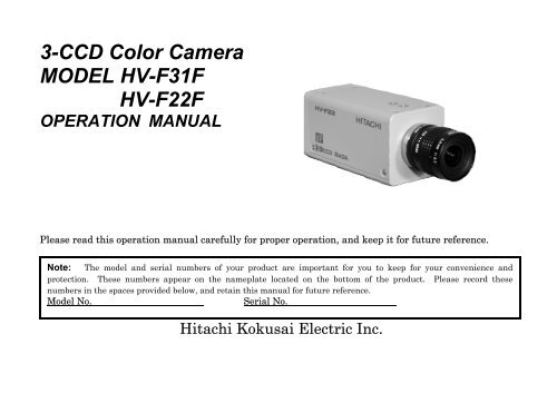
3-CCD Color Camera<br />
MODEL <strong>HV</strong>-<strong>F31F</strong><br />
<strong>HV</strong>-F22F<br />
OPERATION MANUAL<br />
Please read this operation manual carefully for proper operation, and keep it for future reference.<br />
Note: The model and serial numbers of your product are important for you to keep for your convenience and<br />
protection. These numbers appear on the nameplate located on the bottom of the product. Please record these<br />
numbers in the spaces provided below, and retain this manual for future reference.<br />
Model No. Serial No.<br />
<strong>Hitachi</strong> <strong>Kokusai</strong> <strong>Electric</strong> Inc.
IMPORTANT SAFETY INSTRUCTIONS<br />
1. Read Instructions<br />
All the safety and operating instructions should<br />
be read before the product is operated.<br />
2. Retain Instructions<br />
The safety and operating instructions should be<br />
retained for future reference.<br />
3. Heed Warnings<br />
All warnings on the product and the operating<br />
instructions should be adhered to.<br />
4. Follow Instructions<br />
All operating and use instructions should be<br />
followed.<br />
5. Cleaning<br />
Unplug this product from the wall outlet before<br />
cleaning. Do not use liquid cleaners or aerosol<br />
cleaners. Use a damp cloth for cleaning.<br />
6. Attachments<br />
Do not use attachments not recommended by the<br />
product manufacturer as they may cause<br />
hazards.<br />
7. Water and Moisture<br />
Do not use this product near water - for example,<br />
near a bath tub, wash bowl, kitchen sink, or<br />
laundry tub; in a wet basement; or near a<br />
swimming pool; and the like.<br />
8. Accessories<br />
Do not place this product on an unstable cart,<br />
stand, tripod, bracket, or table. The product may<br />
fall, causing serious injury to a child or adult, and<br />
serious damage to the product. Use only with a<br />
cart, stand, tripod, bracket, or table recommended<br />
by the manufacturer, or sold with the product.<br />
Any mounting of the product should follow the<br />
manufacturer's instructions, and should use a<br />
mounting accessory recommended by the<br />
manufacturer.<br />
9. Moving<br />
A product and cart combination should be moved<br />
with care.<br />
Quick stops, excessive force, and uneven surfaces<br />
may cause the product and cart combination to<br />
overturn.<br />
10. Ventilation<br />
Slots and openings in the cabinet are provided for<br />
ventilation and to ensure reliable operation of the<br />
product and to protect it from overheating, and<br />
these openings must not be blocked or covered.<br />
The openings should never be blocked by placing<br />
the product on a bed, sofa, rug, or other similar<br />
surface. This product should not be placed in a<br />
A
uilt-in installation such as a bookcase or rack<br />
unless proper ventilation is provided or the<br />
manufacturer's instructions have been adhered<br />
to.<br />
11. Power Sources<br />
This product should be operated only from the<br />
type of power source indicated on the marking<br />
label. If you are not sure of the type of power<br />
supply to your home, consult your product dealer<br />
or local power company. For products intended<br />
to operate from battery power, or other sources,<br />
refer to the operating instructions.<br />
12. Grounding or Polarization<br />
This product is equipped with a three-wire<br />
grounding-type plug a plug having a third<br />
(grounding) pin. This plug will only fit into a<br />
grounding-type power outlet. This is a safety<br />
feature. If you are unable to insert the plug into<br />
the outlet, contact your electrician to replace<br />
your obsolete outlet. Do not defeat the safety<br />
purpose of the grounding-type plug.<br />
13. Power-Cord Protection<br />
Power-supply cords should be routed to that they<br />
are not likely to be walked on or pinched by items<br />
placed upon or against them, paying particular<br />
attention to cords at plug, convenience<br />
receptacles, and the point where they exit from<br />
the product.<br />
14. Lightning<br />
For added protection for this product during a<br />
lightning storm, or when it is left unattended and<br />
unused for long periods of time, unplug it from<br />
the wall outlet. This will prevent damage to the<br />
product due to lightning and power-line surges.<br />
15. Overloading<br />
Do not overload wall outlets, extension cords or<br />
integral convenience receptacles as this can result<br />
in a risk of fire or electric shock.<br />
16. Object and Liquid Entry<br />
Never push objects of any kind into this product<br />
through openings as they may touch dangerous<br />
voltage points or short-out parts that could result<br />
in a fire or electric shock. Never spill liquid of<br />
any kind on the product.<br />
17. Inflammable and Explosive Substance<br />
Avoid using this product where there are gases,<br />
and also where there are inflammable and<br />
explosive substances in the immediate vicinity.<br />
18. Heavy Shock or Vibration<br />
When carrying this product around, do not subject<br />
the product to heavy shock or vibration.<br />
B
19. Servicing<br />
Do not attempt to service this product yourself as<br />
opening or removing covers may expose you to<br />
dangerous voltage or other hazards. Refer all<br />
servicing to qualified service personnel.<br />
20. Damage Requiring Service<br />
Unplug this product from the wall outlet and<br />
refer servicing to qualified service personnel<br />
under the following conditions:<br />
a.When the power-supply cord or plug is<br />
damaged.<br />
b.If liquid has been spilled, or objects have fallen<br />
into the product.<br />
c. If the product has been exposed to rain or<br />
water.<br />
d.If the product does not operate normally by<br />
following the operating instructions. Adjust<br />
only those controls that are covered by the<br />
operating instructions as an improper<br />
adjustment of other controls may result in<br />
damage and will often require extensive work<br />
by a qualified technician to restore the product<br />
to its normal operation.<br />
e. If the product has been dropped or damaged in<br />
any way.<br />
f. When the product exhibits a distinct change in<br />
performance-this indicates a need for service.<br />
21. Replacement Parts<br />
When replacement parts are required, be sure the<br />
service technician has used replacement parts<br />
specified by the manufacturer or have the same<br />
characteristics as the original part.<br />
Unauthorized substitutions may result in fire,<br />
electric shock, or other hazards.<br />
22. Safety Check<br />
Upon completion of any service or repairs to this<br />
product, ask the service technician to perform<br />
safety checks to determine that the product is in<br />
proper operating condition.<br />
23. Wall or Ceiling Mounting<br />
The product should be mounted to a wall or<br />
ceiling only as recommended by the<br />
manufacturer.<br />
24. Heat<br />
The product should be situated away from heat<br />
sources such as radiators, heat registers, stoves,<br />
or other products (including amplifiers) that<br />
produce heat.<br />
C
WICHTIGE SICHERHEITSANWEISUNGEN<br />
1. Alle Anweisungen lesen<br />
Vor Betrieb des Erzeugnisses sollten alle<br />
Sicherheits-und Bedienungsanleitungen gelesen<br />
werden.<br />
2. Die Anweisungen aufbewahren<br />
Die Sicherheits-und Bedienungsanleitungen<br />
sollten fünftigen Bezug aufbewahrt werden.<br />
3. Warnungen beachten<br />
Die Warnungen auf dem Erzeugnis und in den<br />
Bedienungsanleitungen solten beachtet werden.<br />
4. Anweisungen befolgen<br />
Alle Bedienungsanleitung-und<br />
Verwendungsanweisungen sollten befolgt werden.<br />
5. Reinigung<br />
Den Stecker des Geräts vor Reinigung aus der<br />
Steckdose ziehen. Keine flüssigen Reinigungsmittel<br />
oder Aerosolreiniger verwenden. Zum Reinigen<br />
einen feuchten Lappen verwenden.<br />
6. Zubehör<br />
Nur vom-Hersteller des Erzeugnisses empfohlenes<br />
Zubehör verwenden, da es sonst zu Störungen<br />
kommen kann.<br />
7. Wasser und Feuchtigkeit<br />
Dieses Erzeugnis nicht in der Nähe von Wasser<br />
verwenden - z.B, in der Nähe einer Badewanne,<br />
eines Waschbeckens, einer Küchenspüle, eines<br />
Waschzubers, in einem nassen Keller, in der Nähe<br />
eines Schwimmbeckens usw.<br />
8. Aufstellung<br />
Das Erzeugnis nicht auf einen unstabilen Wagen,<br />
Stand, Dreifuß, Träger oder Tisch stellen.<br />
Das Erzeugnis kann sonst herunterfallen und ein<br />
kind oder einen Erwachsenen schwer verietzen.<br />
Außerdem kann das Gerät schwer beschädigt<br />
werden. Nur mit einem Wagen, Stand, Dreifuß,<br />
Träger oder Tisch verwenden, der vom Hersteller<br />
empfohlen oder mit dem Erzeugnis verkauft<br />
worden ist. Für jegliche Anbringung sollten die<br />
Anweisungen des Herstellers befolgt werden, und<br />
das vom Hersteller empfohlene Anbringungszubehör<br />
sollte verwendet werden.<br />
9. Eine Kombination von Erzeugnis und Wagen<br />
sollte vorsichtig bewegt werden<br />
Schneller Halt, übermäßige Krafteinwirkung und<br />
unebene Oberflächen können Umkippen der<br />
kombination von Erzeugnis und Wagen<br />
verursachen.<br />
10. Ventilation<br />
Schlitze und Öffnungen im Gehäuse dienen der<br />
Ventilation. Sie sind für zuverlässigen Betrieb<br />
des Gerätes und Schutz vor Überhitzung<br />
D
erforderlich und dürfen nicht blockiert oder abgedeckt<br />
werden.<br />
Die Öffnungen sollten niemals dadurch blockiert<br />
werden, daß, das Gerät auf ein Bett, ein Sofa,<br />
einen Teppich oder eine ähnliche Oberfläche<br />
gestellt wird.<br />
Das Gerät sollte nur dann in Einbauinstallierung<br />
wie in einem Bücherschrank oder einem Gestell<br />
verwendet werden, wenn angemessene<br />
Ventilation vorgesehen ist bzw. Die<br />
Anweisungen des Herstellers befolgt worden<br />
sind.<br />
11. Stromversorgung<br />
Dieses Erzeugnis sollte nur an der auf dem<br />
Typenschild angegebenen Stromversorgungsart<br />
betrieben werden. Wenn Sie nicht sicher sind,<br />
was für eine Stromversorgung Sie haben, so<br />
wenden Sie sich bitte an Ihren Erzeugnishändler<br />
oder an das lokale Elektrizitätswerk. Beziehen<br />
Sie sich für Batteriebetrieb oder andere<br />
Stromquellen vorgesehene Erzeugnisse bitte auf<br />
die Bedienungsanleitungen.<br />
12. Erdung oder Polarisierung<br />
Dieses Erzeugnis ist mit einem<br />
Schutzkontaktstecker mit drei Leitern ausgerüstet,<br />
mit einem Erdungskontakt. Dieser Stecker paßt<br />
nur in ein schuko-Steckdose. Dies ist eine<br />
Sicherheitsmaßnahme. Wenn Sie den Stecker<br />
nicht in die Steckdose stecken können, so wenden<br />
Sie sich bitte an ihren Elektriker, damit er die<br />
veraltete Schuts des Schutzkontaktsteckers<br />
unwirksam.<br />
13. Netzkabelschutz<br />
Netzkabel sollten so verlegt werden, deß möglichst<br />
nicht darauf getreten wird und daß sie nicht<br />
eingeklemmt werden, mit besonderer Beachtung<br />
der kabel an Stackern, Verlängerungskabeln und<br />
dem Austritt des Kabels aus dem Erzeugnis.<br />
14. Blitzschlag<br />
Für zusätzlichen Schutz des Erzeugnisses während<br />
eines Gewitters oder bei Nichtverwendung für<br />
lange Zeit den Stecker aus der Steckdose ziehen.<br />
Dies verhütet Beschädigung durch Blitzschlag und<br />
Netzspannungsstöße.<br />
15. Überlastung<br />
Wandsteckdosen, Verlängerungskabel und<br />
eingebaute Bequemlickkeitssteckdosen nicht<br />
überlasten, da dies Feuer oder elektrischen<br />
Schlag verursachen kann.<br />
E
16. Eindringen von Fremdkörpern und Flüssigkeit<br />
Niemals Objekte irgendwelcher Art durch die<br />
Öffnungen in das Gerät schieben, da diese unter<br />
hoher Spannung stehende Teile berühren oder<br />
kurzschließen können, wodurch es zu Feuer oder<br />
elektrischem Schlag kommen kann. Niemals<br />
Flüssigkeiten irgendwelcher Art auf das<br />
Erzeugnis verschütten.<br />
17. Entflammbare und explosive Substanzen<br />
Vermeiden Sie Verwendung dieses Erzeugnisses<br />
an Orten mit Gasen bzw. entflammbaren oder<br />
explosiven Substanzen in der direkten<br />
Umgebung.<br />
18. Starke stöße oder Vibrationen<br />
Setzen Sie das Erzeugnis beim Transport nicht<br />
starken Stößen oder Vibrationen aus.<br />
19. Wartung<br />
Versuchen Sie nicht, dieses Erzeugnis Selbst zu<br />
warten, da Sie sich durch Öffnen bzw.<br />
Entfernen von Abdeckungen hohen Spannungen<br />
und sonstigen Gefährdungen ausserzen können.<br />
Beziehen Sie sich für jegliche Wartung auf<br />
qualifiziertes Wartungspersonal.<br />
20. Beschädigung, die Wartung erfordert<br />
Ziehen Sie den Stecker dieses Erzeugnisses aus<br />
der Steckdose und wenden Sie sich an<br />
F<br />
qualifiziertes Wartungspersonal, wenn eine der<br />
folgenden Bedingungen vorliegt:<br />
a. Wenn das Netzkabel oder der Stecker<br />
beschädigt ist.<br />
b. Bei Eindringen von Flüssigkeit oder<br />
Fremdkörpern in das Gerät.<br />
c. Wenn das Erzeugnis Regen oder Wasser<br />
ausgesetzt worden ist.<br />
d. Wenn das Erzeugnis bei Befolgen der<br />
Bedienungsanleitungen nicht normal<br />
funktioniert.<br />
Nur die Regelelemente verstellen, die in den<br />
Bedienungsanleitungen behandelt werden, da<br />
unangemessene Einstellung anderer<br />
Regelelemente Beschädigung verursachen kann<br />
und oft beträchtliche Arbeit durch einen<br />
qualifizierten Techniker erfordert, um das<br />
Erzeugnis wieder, zu normalem Betrieb<br />
zurückzubringen.<br />
e. Wenn das Erzeugnis fallen gelassen oder<br />
beschädigt worden ist.<br />
f. Wenn das Erzeugnis eine klare Änderung in<br />
der Leistung zeigt-dies weist darauf hin, daß<br />
Wartung erforderlich ist.
21. Ersatzteile<br />
Wenn Ersatzteile erforderlich sind, darauf<br />
achten, daß der Wartungstechniker nur die vom<br />
Hersteller festgelegten Ersatzteile oder Teile mit<br />
den gleichen Charakteristiken wie die<br />
ursprünglichen Teile verwendet. Unautorisierte<br />
Ersatzteile können Feuer, elektrischen Schlag<br />
oder sonstige Gefährdungen verursachen.<br />
22. Sicherheitsprüfung<br />
Bitten Sie den Wartungstechniker nach der<br />
Vollendung von Wartung oder Reparaturarbeiten<br />
an diesem Erzeugnis um die Durchführung von<br />
Sicherheitsprüfungen, um zu bestimmen, daß das<br />
Erzeugnis im angemissenen Betriebszustand ist.<br />
23. Anbringung an der Wand oder an der Decke<br />
Das Erzeugnis sollte nur entsprechend den<br />
Empfehlungen des Herstellers an einer Wand<br />
oder an der Decke angebracht werden.<br />
24. Wärme<br />
Das Erzeugnis sollte fern von Wärmequellen wie<br />
Radiatoren, Heizwiderständen, Öfen und anderen<br />
Wärme erzeugenden Erzeugnissen (einschließlich<br />
Verstärkern) aufgestellt werden.<br />
G
MISES EN GARDE IMPORTANTES<br />
1. Lire les instructions<br />
Lire toutes les instructions de sécurité et de<br />
fonctionnement avant de faire fonctionner<br />
l’appareil.<br />
2. Conserver ces instructions<br />
Conserver les instructions de sécurité et de<br />
fonctionnement á des fins de référence ultérieure.<br />
3. Tenir compte des avertissements<br />
Tous les avertissements qui figurent sur<br />
l’appareil et dans le mode d’emploi devront être<br />
respectés.<br />
4. Observer les instructions<br />
Observer toutes les instructions de<br />
fonctionnement et d’utilisation.<br />
5. Nettoyage<br />
Avant de procéder au nettoyage, débrancher<br />
l’appareil de la prise secteur. Ne pas utiliser<br />
de produits de nettoyage liquides ou en aérosol.<br />
Nettoyer l’appareil avec un chiffon humide.<br />
6. Fixations<br />
Ne pas utiliser de fixations non recommandées<br />
par le fabricant de l’appareil car elles<br />
pourraient être source de danger.<br />
7. Eau et humidité<br />
Ne pas utiliser l’appareil á proximité d’eau-ar exemple<br />
prés d’une baignoire, d’un lavabo, d’un évier<br />
H<br />
ou d’un bac á lessive, dans un sous-sol humide,<br />
ou prés d’une piscine, etc.<br />
8. Accessoires<br />
Ne pas placer l’appareil sur un chariot, un socle,<br />
un pied, un support ou one table instables<br />
L’appareil pourrait tomber, blessant griévement<br />
des enfants ou des adultes, et étant sérieusement<br />
endommagé.<br />
Utiliser exclusivement le chariot, le socle, le pied,<br />
le support ou la table recommandés par le<br />
fabricant, ou vendus avec l’appareil. Pour tout<br />
montage de l’appareil, respecter les instructions<br />
du fabricant, et utiliser á cette fin l’accessoire de<br />
montage recommandé par le fabricant.<br />
9. L’appareil monté sur son chariot devra être<br />
déplacé avec précaution<br />
Des arrêts brusques, une force excessive et des<br />
surfaces irréguliéres pourraient provoquer le<br />
renversement de l’ensemble appareil-chariot.<br />
10. Ventilation<br />
Les fentes et les ouvertures du coffret sont<br />
prévues pour la ventilation ainsi que pour<br />
garantir un fonctionnement en toute sécurité de
l’appareil et le protéger de toute surchauffe, et<br />
ces ouvertures ne devront donc être ni<br />
obstruées ni recouvertes. Ne jamais obstruer les<br />
ouvertures en placant l’appareil sur un lit, un<br />
sofa, un tapis ou toute surface similaire. Ne<br />
jamais placer l’appareil dans un support confiné,<br />
par exemple une bibliothéque ou une é tagé re,<br />
sans ventilation suffisante ou sans repecter les<br />
instructions du fabricant.<br />
11. Sources d’allmentation<br />
L’appareil devra être alimenté exclusivement sur<br />
le type d’alimentation indiqué sur l’étiquette<br />
signalétique. Sil’on n’est pas sûr du type<br />
d’alimentatio du local, consulter le revendeur de<br />
l’appareil ou la compagnie d’électricité locale.<br />
Pour les appareils qui fonctionnent sur batterie<br />
ou sur d’autres sources, voir le mode d’emploi.<br />
12. Mise á la terre ou polarisation<br />
L’appareil est doté d’une fiche trifilaire avec mise<br />
á la terre, dont la troisiéme broche assure la mise<br />
á la terre. Cette fiche ne rentrera que dans les<br />
prises trifilaires de mise á la terre. Ceci est une<br />
mesure de sécurité. Si la fiche ne rentre pas<br />
dans la prise, faire remplacer la prise désuéte par<br />
un électricien.<br />
Ne pas rendre vaine la measure de sécurité<br />
assurée par cette prise avec mise á la terre.<br />
13. Protection du cordon d’alimentation<br />
Acheminer les cordons d’alimentation de facon<br />
qu’on ne risque pas de marcher dessus ou de les<br />
coincer sous un objet placé dessus ou contre eux.<br />
Faire particuliérement attention aux fiches des<br />
cordons, á la proximité des prises, et á l’endroit oú<br />
ils ressortent de l’appareil.<br />
14. Foudre<br />
Pour renforcer la protection de l’appareil pendant<br />
un orage, ou si l’on s’en éloigne ou qu’on reste<br />
longtemps sans l’utiliser, le débrancher de la<br />
source d’alimentation. Ceci permettra d’éviter<br />
tout dommage de l’appareil dú á la foudre et aux<br />
surtensions de ligne.<br />
15. Surcharge<br />
Ne pas surcharger les prises, rallonges et prises<br />
multiples car cela pourrait entraîner un risque de<br />
feu ou de choc électrique.<br />
16. Pénétration d’objets et de liquides<br />
Ne jamais enfoncer d’objets d’aucune sorte dans<br />
les ouvertures de l’appareil car ils pourraient<br />
toucher des points de tension dangereuse ou<br />
court-circuiter des piéces, ce qui pourrait<br />
I
provoquer un feu ou un choc électrique. Ne<br />
jamais renverser de liquide d’aucune sorte sur<br />
l’appareil.<br />
17. Substances inflammabes et explosives<br />
Eviter d’utiliser l’appareil en présence de gaz,<br />
ainsi qu’á proximité immédiate de substances<br />
inflammables et explosives.<br />
18. Chocs ou vibrations violents<br />
Lorsqu’on transporte l’appareil, ne pas le<br />
soumettre á des chocs ou des vibrations violents.<br />
19. Réparations<br />
Ne pas tenter de réparer l’aapareil soi-même car<br />
le fait d’ouvrir ou de retirer les caches risque<br />
d’exposer l’utilisateur á des tensions dangereuses<br />
notamment. Confier toute réparation á un<br />
personnel qualifié.<br />
20. Dommages nécessitant réparations<br />
Débrancher l’appareil de la source d’alimentation<br />
et confier les réparations á un personnel qualifié<br />
dans les cas suivants:<br />
a. Lorsque le cordon d’alimentation ou sa fiche<br />
sont endommagés<br />
b. Si du liquide s’est renversé sur l’appareil ou<br />
que des objets sont tombés dedans<br />
c. Si l’appareil a été exposé á la pluie ou á l’eau.<br />
d. Si l’appareil ne fonctionne pas normalement<br />
lorsqu’on observe les instructions d’utilisation.<br />
Ne régler que les commandes couvertes par le<br />
mode d’emploi ; en effet, un réglage incorrect<br />
des autres commandes pourrait entrainer des<br />
dommages et nécessiteront souvent des travaux<br />
de réparation coûteux par un technicien qualifié<br />
pour remettre l’appareil en état de marche.<br />
e. Si l’appareil est tombé ou qu’il a été<br />
endommagé.<br />
f. Si l’appareil affiche une nette modification de<br />
ses performances, cela signifie qu’il a besoin<br />
d’être réparé.<br />
21. Piéces de rechange<br />
Si l’on a besoin de piéces de rechange, veiller á ce<br />
que le technicien de réparation utilise<br />
exclusivement les piéces de rechange spécifiées<br />
par le fabricant ou des piéces ayant les mêmes<br />
caractéristiques que les piéces d’origine. Les<br />
piéces de rechange non autorisées risquent de<br />
provoquer un feu, un choc électrique et autres<br />
dangers.<br />
J
22. Vérificaton de sécurité<br />
Aprés tout travail d’entretien ou de réparation de<br />
l’appareil, demander au technicien de réparation<br />
d’effectuer les vérifications de sécurité pour<br />
s’assurer que l’appareil est en bon état de<br />
marche.<br />
23.Montage au mur ou au plafond<br />
L’appareil ne pourra être monté au mur ou au<br />
plafond que de la maniére recommandée par le<br />
fabricant.<br />
24. Chaleur<br />
Eloigner l’appareil des sources de chaleur, telles<br />
que radiateurs, appareils de chauffage,<br />
cuisiniéres, et de tour produit engendrant de la<br />
chaleur (y compris les amplificateurs).<br />
K
IMPORTANT NOTICE<br />
For USA<br />
These products have been tested and found to<br />
comply with the limits for a Class A digital<br />
device, pursuant to Part 15 of the FCC Rules.<br />
These limits are designed to provide<br />
reasonable protection against harmful<br />
interference when the equipment is operated<br />
in a commercial environment. This<br />
equipment generates, uses, and can radiate<br />
radio frequency energy and, if not installed<br />
and used in accordance with the instruction<br />
manual, may cause harmful interference to<br />
radio communications. <strong>Op</strong>eration of this<br />
product in a residential area is likely to cause<br />
harmful interference in which case the user<br />
will be required to correct the interference at<br />
his own expense.<br />
WARNING<br />
Changes or modifications not expressly<br />
approved by <strong>Hitachi</strong> Denshi responsible for<br />
compliance could void the user’s authority to<br />
operate the equipment.<br />
For Canada<br />
This product does not exceed the class A/class<br />
B limits for radio noise emissions from digital<br />
apparatus as set out in the radio interference<br />
regulations.<br />
Le présent appareil n’émet pas de bruits<br />
radioélectriques dépassant les limités<br />
applicable aux appareils numériques de classe<br />
A prescrites dans le rVglement sur le<br />
brouillage radioélectrique édicter par le<br />
ministére des communications du canada.<br />
L
Table of contents<br />
• IMPORTANT SAFETY INSTRUCTUIONS ・・ A<br />
• IMPORTANT NOTICE ・・・・・・・・・・・・・・・・・・・ L<br />
• Table of contents ・・・・・・・・・・・・・・・・・・・・・・・・・ M<br />
• Standard composition ・・・・・・・・・・・・・・・・・・・・・ 1<br />
• CD-ROM ・・・・・・・・・・・・・・・・・・・・・・・・・・・・・・・・・ 1<br />
• Overview ・・・・・・・・・・・・・・・・・・・・・・・・・・・・・・・・ 3<br />
• Features ・・・・・・・・・・・・・・・・・・・・・・・・・・・・・・・・・ 3<br />
• Notes to users ・・・・・・・・・・・・・・・・・・・・・・・・・・・・ 4<br />
Important safety notes・・・・・・・・・・・・・・・・・・・ 4<br />
<strong>Op</strong>erating considerations ・・・・・・・・・・・・・・・・ 4<br />
CCD properties ・・・・・・・・・・・・・・・・・・・・・・・・・ 5<br />
• System example ・・・・・・・・・・・・・・・・・・・・・・・・・・・ 7<br />
• Section names and functions ・・・・・・・・・・・・・・・ 8<br />
• Connectors ・・・・・・・・・・・・・・・・・・・・・・・・・・・・・・・ 9<br />
• LENS ・・・・・・・・・・・・・・・・・・・・・・・・・・・・・・・・・・・ 10<br />
• Camera mounting ・・・・・・・・・・・・・・・・・・・・・・・・ 11<br />
• Control and status register (CSR) ・・・・・・・・・ 12<br />
IIDC standard CSR・・・・・・・・・・・・・・・・・・・・・ 13<br />
Advanced CSR ・・・・・・・・・・・・・・・・・・・・・・・・・ 20<br />
Image color reproduction and<br />
Color balance related CSR ・・・・・・・・・・ 20<br />
Image quality related CSR・・・・・・・・・・・ 24<br />
Image level related CSR ・・・・・・・・・・・・・ 28<br />
CSR related to other functions ・・・・・・・ 32<br />
• Specifications ・・・・・・・・・・・・・・・・・・・・・・・・・・・・ 36<br />
• Input/Output Signals ・・・・・・・・・・・・・・・・・・・・・ 38<br />
• Trigger operation and timing chart<br />
<strong>HV</strong>-<strong>F31F</strong>・・・・・・・・・・・・・・・・・・・・・・・・・・・・・・・・・ 41<br />
<strong>HV</strong>-F22F・・・・・・・・・・・・・・・・・・・・・・・・・・・・・・・・・ 43<br />
• External sync operation timing ・・・・・・・・・・・・ 45<br />
• Dimensions ・・・・・・・・・・・・・・・・・・・・・・・・・・・・・・ 46<br />
M
Standard composition<br />
Check when unpacking.<br />
Camera <strong>HV</strong>-<strong>F31F</strong>/<strong>HV</strong>-F22F ・・・・・・・・・・・・・・・・・・・・・・・・・・・・・・・・・・・・・・・・・・・・・・・・・・・・・・・・・・・・・ 1<br />
DC IN/SYNC plug (HR10A-10P-12S) ・・・・・・・・・・・・・・・・・・・・・・・・・・・・・・・・・・・・・・・・・・・・・・・・・・ 1<br />
CD ROM (IIDC Driver and demonstration viewer software) ・・・・・・・・・・・・・・・・・・・・・・・・・・・ 1<br />
<strong>Op</strong>eration manual ・・・・・・・・・・・・・・・・・・・・・・・・・・・・・・・・・・・・・・・・・・・・・・・・・・・・・・・・・・・・・・・・・・・・・・・ 1<br />
CD-ROM<br />
An IEEE1394 driver and demonstration viewer software that displays an image to PC monitor and<br />
control the camera functions are included within the belonging CD-ROM.<br />
As for the installation procedure of an<br />
IEEE1394 driver and viewer software,<br />
please read the installation manual and<br />
operation manual within CD-ROM<br />
carefully.<br />
Viewer Software<br />
1
NOTE:<br />
1) The included driver and also demonstration software within CD-ROM operate only in Windows 98<br />
SE/ME/2000/XP.<br />
2) The viewer software may not operate normal when it is used for the other camera, because<br />
software for <strong>HV</strong>-<strong>F31F</strong> and <strong>HV</strong>-F22F.<br />
3) In the case that it stopped normal operating during the use of viewer software, stop a viewer<br />
software, turn off and on the camera power supply or pull and push the IEEE1394 cable, execute<br />
viewer software once again.<br />
4) In the case that the performance (the CPU clock, installation memory etc.) of PC is not sufficient,<br />
viewer software may not execute normally. Please use PC of following specification.<br />
Item<br />
CPU<br />
Memory<br />
Display Card<br />
Interface Card<br />
<strong>Op</strong>erating System<br />
Others<br />
Specifications<br />
Intel Celeron 533MHz or more<br />
256MByte or more<br />
24bit RGB color display card or more<br />
built-in OHCI IEEE1394 port or PCI-Card or PC-Card<br />
Windows 98SE / Me / 2000 / XP<br />
DirectX 8.0 or more<br />
5) <strong>Hitachi</strong> kokusai <strong>Electric</strong>. Inc does not guarantee it, regarding the faulty, damage of the hardware<br />
and also software of the customer by a driver and also viewer software.<br />
2
Overview<br />
The <strong>Hitachi</strong> <strong>HV</strong>-<strong>F31F</strong>/<strong>HV</strong>-F22F are high precision 3CCD progressive scan color camera, which has<br />
single chip digital processing LSI, a C mount prism, three 1/3-inch 800,000 pixels (<strong>HV</strong>-<strong>F31F</strong>) / 1/2-inch<br />
1,450,000 pixels (<strong>HV</strong>-F22F) square CCDs , and an IEEE1394 digital output.<br />
A newly developed multi-functional LSI use the accurate 14 bit digital processing technology, which<br />
performs the high picture quality signal processing and the picture compensating functions, beyond the<br />
capability of the other conventional analog cameras. The IEEE1394 interface reduces the system cost<br />
without an image capturing board and special connecting cable.<br />
Features<br />
• Camera signal processor is single chip LSI.<br />
The <strong>Hitachi</strong>’s most advanced technology (0.18 um design process, 1.8V internal core drive voltage)<br />
produces a single newly developed ultra LSI chip (3 million gates), and contributes to the downsizing<br />
and the low power of the camera. In addition, the 12-bit A/D converter and 14 bit internal processor<br />
provide high S/N and wide dynamic range.<br />
• High quality picture<br />
Excellent color reappearance and high definition are materialized by CCD with a high sensitivity micro<br />
lens and LSI signal processing technology.<br />
• 6 vector masking<br />
Independent six colors masking is the <strong>Hitachi</strong> innovation for optimizing color balance. The saturation<br />
and the hue of 6 colors (Red, blue, green, cyan, magenta and yellow) are adjusted independently to<br />
deliver the best color in image capture, microscope and other applications.<br />
• Auto white shading compensation<br />
Color shading due to the aberration of C mount lens is automatically compensated (reduced).<br />
3
Notes to users<br />
Important safety notes<br />
• Use this camera with a 12 VDC power supply.<br />
• Observe that flammable objects, water or metal<br />
do not enter the camera interior. These may<br />
lead to failure or accident.<br />
• Do not modify the camera or use the camera with<br />
external covers removed. These may cause<br />
failure, void any warranties and pose a safety<br />
hazard.<br />
• Stop using the camera at the approach of an<br />
electrical storm (thunder audible). Protect the<br />
camera from rain if using it outdoors.<br />
• In event the camera shows any abnormality,<br />
switch off the camera and disconnect the power<br />
cord. Contact a <strong>Hitachi</strong> Denshi service<br />
representative.<br />
<strong>Op</strong>erating considerations<br />
• Power supply<br />
Check that the supplied voltage is between 10.5<br />
and 15 VDC. Inadequate voltage can affect color<br />
fidelity and cause noise, while voltage over 15 V<br />
can damage the camera.<br />
• Connectors<br />
Confirm the power is off before connecting or<br />
disconnecting a signal cable. Grasp connectors<br />
by the body, not the attached wires.<br />
• Lens<br />
The correct lens is important for deriving<br />
optimum performance from the camera. Consult<br />
a <strong>Hitachi</strong> Denshi dealer for a selection of fine<br />
lenses according to the application.<br />
• Installation and storage sites<br />
The following types of environment can impair<br />
performance, lead to damage, pose safety hazards<br />
and shorten the useful life of the camera. Select<br />
the sites for installing the storing the camera<br />
carefully.<br />
• Direct sunlight, rain or snow<br />
• Flammable or corrosive gasses<br />
• Very hot or cold (beyond 0 to 4 ℃ operating,<br />
-20 to 60 ℃ storage)<br />
• Humid or dusty<br />
• Exposed to vibration or shock<br />
• Strong electrical or magnetic fields<br />
• Exceptionally strong light<br />
•<br />
Continuous operation<br />
In situations where the camera is used<br />
continuously for long periods of time, the ambient<br />
temperature should be kept below 40 ℃ in order<br />
to avoid accelerated deterioration of internal<br />
parts and to derive maximum long-term<br />
reliability.<br />
4
Cleaning<br />
• A photographer’s blower or lens brush can be used for clearing dust from the lens and optical filters.<br />
• Wipe dust from the case with a soft dry cloth. If soiling is severe, moisten the cloth with a solution of neutral<br />
detergent. Afterwards, wipe the cover with a dry cloth.<br />
• Do not use petroleum distillates, alcohol or spray type cleaners.<br />
Transportation<br />
Remove the lens (install lens mount cap) and other attachments. Pack the camera carefully in its original or<br />
equivalent container. Use ample cushioning to protect the camera from physical shock.<br />
CCD properties<br />
The following phenomena are inherent to a charge coupled device imaging element and do not indicate<br />
malfunction.<br />
1) Smear and blooming<br />
Vertical bands are visible when a strong light enters the scene. Adjust the camera aiming direction<br />
carefully to avoid strong direct or reflected light.<br />
2) Fixed pattern noise<br />
High ambient temperature can cause fixed pattern noise to appear throughout the scene.<br />
5
3) Moire<br />
Interaction between patterns can produce an additional "phantom" pattern to appear. The CCD picture<br />
elements (pixels) are arranged in a pattern, which can interact with a pattern in the scene (e.g., a<br />
performer wearing a finely striped necktie) to result in a Moire pattern. The effect should be considered<br />
when selecting costumes, props and other scene elements.<br />
4) Ghosting<br />
Strong direct or reflected light near an object of interest can cause ghosting of the object to appear in the<br />
picture. The effect is more obtrusive with certain iris settings and lens types. Select the scene layout<br />
and camera pointing direction carefully in order to avoid this effect.<br />
6
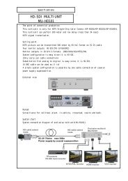
System example<br />
Computer Image<br />
Processing &<br />
F A<br />
PC<br />
Lens H V -<strong>F31F</strong>/F22 F<br />
Camera Cable<br />
C-201KSM<br />
/C501KSM<br />
/C102KSM<br />
Junction Box<br />
JU-M1A<br />
Laptop PC<br />
External<br />
T rigge r<br />
AC adaptor<br />
7
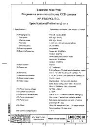
Section names and functions<br />
Camera mounting<br />
screw holes<br />
DC IN/SYNC connector<br />
Connect to +12 VDC power supply.<br />
Input for external HD/VD and sync<br />
signals.<br />
Lens mount<br />
(C mount)<br />
TRIG IN connector<br />
External trigger signal input<br />
Pilot lamp<br />
Light when power is<br />
supplied.<br />
Status lamp<br />
Flashes when<br />
transmitting<br />
Camer mounting<br />
screw holes<br />
(see Note)<br />
IEEE1394 connector<br />
IEEE1394 cable computer side<br />
IEEE1394 connector end<br />
Note<br />
When power is supplied from IEEE1394,<br />
check for proper current and voltage. If not<br />
correctly indicated, a separate power supply<br />
is required.<br />
8
Connector<br />
1. IEEE1394 connector 2. DC IN/SYNC connector<br />
(HR10A-10R-12PB(01))<br />
Pin No. Signal designation Pin NO. Signal designation<br />
1 +12V input 1 GND<br />
2 GND 2 +12V input<br />
3 TPB- 3 GND<br />
4 TPB+ 4 FLASH OUT<br />
5 TPA- 5 GND<br />
6 TPA+ 6 HD IN<br />
7 VD IN<br />
8 GND<br />
9 TRIG (H)<br />
10 TRIG (C)<br />
11 +12V input<br />
12 GND<br />
Plug:HR10A-10P-12S<br />
2<br />
4<br />
6<br />
1<br />
3<br />
5<br />
9
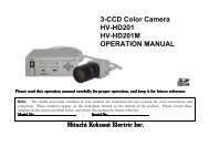
Lens<br />
CAUTION:<br />
Observe the dimensions of the lens mounting<br />
selection as illustrated at the right.<br />
If the dimensions are not observed, do not use<br />
such a lens, because the lens and the camera will<br />
be damaged.<br />
Lens optics<br />
Selecting a lens<br />
The proper lens is important for obtaining<br />
adequate performance from the camera.<br />
Especially in the case of a three elements CCD<br />
system C mount camera, the lens incidence<br />
and exit distances are important. If separation<br />
is too short, color irregularity Is apt to occur at<br />
the top and bottom of the image.<br />
Conversely if too long, where the lens iris is a<br />
nearly fully open, resolution is impaired, while<br />
shading and flare can seriously detract from<br />
image quality. When using 3 CCD color system<br />
camera, it is also recommended to use a lens<br />
designed for this purpose.<br />
Lens flange<br />
<strong>HV</strong>-<strong>F31F</strong>: Max. 4.3mm<br />
<strong>HV</strong>-F22F: Max. 4.0mm<br />
10
Camera mounting<br />
The camera is provided with threaded screw holes at the top and bottom. These allow mounting to either a<br />
tripod or a mounting bracket.<br />
Screw type: U 1/4-20<br />
Length: 4.5 to 6 mm<br />
L<br />
Screws longer than 6 mm can<br />
cause internal damage, while<br />
less than 5 mm prevents secure<br />
fastening and risks dropping to<br />
cause damage and injury.<br />
11
Control and Status register (CSR)<br />
<strong>HV</strong>-<strong>F31F</strong> and <strong>HV</strong>-F22F differ from earlier conventional cameras in that camera functions can be set by<br />
entering predetermined setting commands in the Control and Status register (CSR) of the 1394-based<br />
Digital Camera Specification Ver. 1.30.<br />
Common and camera-specific CSR register setting operations are described below.<br />
Indication example: Function name (CSR: xxxx xxxx h)<br />
Function description<br />
Lower 32 bits of 64 bit CSR address are displayed.<br />
ex: F0F0 0800 h<br />
means BUS_ID, NODE_ID, FFFF F0F0 0800 h.<br />
12
1. IIDC Standard CSR<br />
(1) BRIGHTNESS (CSR: F0F0 0800 h)<br />
Master black level is adjusted<br />
-<strong>Manual</strong> adjustment-<br />
Setting value 820000xx h xx: 00h to FFh (standard 80h)<br />
Can be set in range of 00h to FFh. Setting value to 00h side lowers black level. FFh side raises<br />
black level.<br />
(2) SHARPNESS (CSR: F0F0 0808 h)<br />
Sharpness level adjustment (object contour correction)<br />
-<strong>Manual</strong> adjustment-<br />
Setting value 820000xx h xx: 00h to FFh (standard 80h)<br />
Contour correction can be set in range of 00h to FFh. Setting value toward 00h side reduces<br />
correction for softer contours. Setting toward FFh side increases correction for sharper contours.<br />
(3) WHITE BALANCE (CSR: F0F0 080C h)<br />
White balance adjustment<br />
-<strong>Manual</strong> adjustment-<br />
Setting value 820xx0yy h xx: 00h to FFh (B gain)<br />
yy: 00h to FFh (R gain)<br />
White balance is adjusted manually by adjusting R and B gain. Gain is reduced at 00h side and<br />
raised at FFh side.<br />
13
-One Push Auto White Balance (AWB)-<br />
Setting value 86000000 h<br />
State for automatic white balance adjustment.<br />
-AUTO (ATW)-<br />
Setting value 83000000 h<br />
White balance is adjusted in real time (automatic tracking). An effective function when the scene<br />
is subject to changes in color temperature of the light source. The speed for changing the color<br />
temperature is selected by A. WHT SPEED.<br />
(4) GAIN (CSR: F0F0 0820 h)<br />
<strong>Electric</strong>al sensitivity is adjusted.<br />
-<strong>Manual</strong> adjustment-<br />
Setting value 82000xxx h xxx: 000h to 0C0h (1dB ≒ 010h)<br />
Adjusts electrical sensitivity in the range of 0 to 12 dB.<br />
-AUTO-<br />
Setting value 83000000 h<br />
Gain is automatically adjusted in the range of 0 to 12 dB in response to light source brightness.<br />
(5) SHUTTER (CSR: F0F0-081C h)<br />
Sets electronic shutter speed.<br />
-OFF (<strong>HV</strong>-F22:1/15sec, <strong>HV</strong>-F31:1/30) -<br />
Setting value 80000000 h<br />
Switches off shutter operation.<br />
14
-<strong>Manual</strong> adjustment-<br />
Setting value 82000xxx h xxx: (<strong>HV</strong>-F22) 7C5h to B6Ch / (<strong>HV</strong>-F31) 789h to B27h<br />
Electronic shutter can be set in the range of 4 to 1/100,000 second.<br />
Shutter speed setting value can be derived as follows.<br />
OFF_SPEED = 15 (<strong>HV</strong>-F22), 30 (<strong>HV</strong>-F31).<br />
• Cause of shutter speed ≦ (1 / OFF_SPEED)<br />
a) Setting value obtained from fluorescent time.<br />
nnnh = 800h + log 0.99 ( OFF_SPEED×”Shutter Speed”)<br />
b) Fluorescent time obtained from setting value.<br />
Shutter Speed[sec] = OFF_SPEED × 0.99 (nnn―800h)<br />
Ex. 1 Fluorescent time with <strong>HV</strong>-F31 = setting value nnn to obtain 1/100 second.<br />
800h+ log 0.99 (30×(1/100))<br />
= 800h+ log(30×(1/100)) / log0.99<br />
= 878h<br />
Ex. 2 Setting value nnn that produces 1/100 second fluorescent time with <strong>HV</strong>-<strong>F31F</strong>.<br />
(1/30) × 0.99 (878h-800h) = 1/100(sec)<br />
• Cause of shutter speed > (1 / OFF_SPEED)<br />
a) Setting value obtained from fluorescent time.<br />
nnnh = 801h - ( OFF_SPEED×”Shutter Speed” )<br />
b) Fluorescent time obtained from setting value.<br />
15
Shutter Speed[sec] = (801h – nnn ) / OFF_SPEED<br />
Example Fluorescent time = 1/7.5s usable as setting value nnn with <strong>HV</strong>-<strong>F31F</strong>.<br />
801h - (30×(1/7.5)) = 7FDh<br />
-AUTO-<br />
Setting value 83000000 h<br />
Auto electronic shutter operates to vary the shutter speed in the range of OFF to 1/100,000 second<br />
in response to light source brightness.<br />
If light is excessive, a suitable level is selected for maintaining a video output. This function is<br />
effective when using microscope or other optical system without an automatic lens iris.<br />
(6) AUTO EXPOSURE (CSR: F0F0 0804 h)<br />
At auto gain or shutter setting, the sensitivity is automatically adjusted to maintain the proper video<br />
level.<br />
-<strong>Manual</strong> adjustment-<br />
Setting value 820000xx h xx: 00h to FFh (standard:80 h)<br />
Video level decreases toward 00h and increases toward FFh.<br />
(7) SATURATION (CSR: F0F0 0814 h)<br />
Color saturation is adjusted.<br />
-<strong>Manual</strong> adjustment-<br />
Setting value 820000xx h xx: 00h to FFh (standard: 80 h)<br />
Saturation is reduced toward 00h and raised toward FFh.<br />
16
(8) GAMMA (CSR: F0F0-0818 h)<br />
Gamma correction is adjusted.<br />
-OFF-<br />
Setting value 80000000h<br />
ON3<br />
Gamma correction is set to OFF.<br />
ON2<br />
-<strong>Manual</strong> adjustment-<br />
Setting value 8200000x h x: 0- ON1, 1- ON2, 2- ON3, F- Variable<br />
Positions 1,2 and 3 are effective for additionally fine adjustment<br />
of RGB gamma.<br />
• ON1: Dark component gradation reduced.<br />
OFF<br />
ON1<br />
• ON2: Standard setting<br />
• ON3: Dark component gradation increased.<br />
Input<br />
When setting to Variable, R GAMMA (CSR: F200 0054 h),<br />
G GAMMA (CSR: F200 0058 h), B GAMMA (CSR: F200 005C h) of Setting value become to effect<br />
and adjust the detail gamma.<br />
(9) TRIGGER (CSR: F0F0 0830 h)<br />
Sets external trigger operating mode.<br />
-OFF-<br />
Setting value 80000000 h<br />
Trigger function set to OFF<br />
Output<br />
17
-<strong>Manual</strong> adjustment-<br />
Setting value 8x0y0000 h<br />
x:2- LOW ACTIVE, 3- HIGH ACTIVE<br />
y:0- MDOE0, 1- MODE1<br />
Trigger mode polarity is switched at external signal values x and y.<br />
See trigger operation details and timing chart (page 39).<br />
(10) INITIALIZE (CSR: F0F0 0000 h)<br />
Return equipment to status at time of release from factory.<br />
-Initialization-<br />
Setting value 80000000 h<br />
(11) MEMORY SAVE (EXECUTE) (CSR: F0F0 0618 h)<br />
Make back up of presently effective memory channels.<br />
-BACK UP execute-<br />
Setting value 80000000 h<br />
(12) MEMORY SAVE (Ch SET) (CSR: F0F0 0620 h)<br />
Select channel carried out memory backup.<br />
-channel set-<br />
Setting value x0000000 h x: 1- ch1, 2- ch2, 3- ch3, 4- ch4<br />
(13) CURRENT MEMORY (CSR: F0F0 0624 h)<br />
Loading memory channel designating data<br />
-LOAD BACK UP-<br />
Setting value x0000000 h x: 0- FACTORY SETUP, 1- ch1, 2- ch2, 3- ch3, 4- ch4<br />
18
2. Advance CSR<br />
2-1. Image color reproduction and color balance related CSR<br />
(1) MASKING (CSR: F200 0020 h)<br />
RGB and Ye Cy Mg color saturation and hue can be separately varied (6 vector independent masking). Color<br />
reproduction detail and fidelity are effectively enhanced.<br />
When engaged, R saturation (CSR: F200 0024) - M hue ((CSR: F200 0050) can be set, with color phase<br />
and saturation adjusted for each color phase.<br />
-OFF-<br />
Setting value 80000000 h<br />
-ON-<br />
Setting value 82000000 h<br />
a) (MASKING) R SATURATION (CSR: F200 0024 h)<br />
-<strong>Manual</strong> adjustment-<br />
Setting value 820000xx h xx: 00h to FFh (standard: 80 h)<br />
b) (MASKING) Y SATURATION (CSR: F200 0028 h)<br />
-<strong>Manual</strong> adjustment-<br />
Setting value 820000xx h xx: 00h to FFh (standard: 80 h)<br />
19<br />
c) (MASKING) G SATURATON (CSR: F200 002C h)<br />
-<strong>Manual</strong> adjustment-<br />
Setting value 820000xx h xx: 00h to FFh (standard: 80 h)
d) (MASKING) C SATURATION (CSR: F200 0030 h)<br />
-<strong>Manual</strong> adjustment-<br />
Setting value 820000xx h xx: 00hto FFh (standard: 80 h)<br />
e) (MASKING) B SATURATION (CSR: F200 0034 h)<br />
-<strong>Manual</strong> adjustment-<br />
Setting value 820000xx h xx: 00h to FFh (standard: 80 h)<br />
f) (MASKING) M SATURATION (CSR: F200 0038 h<br />
-<strong>Manual</strong> adjustment-<br />
Setting value 820000xx h xx: 00h to FFh (standard: 80 h)<br />
g) (MASKING) R HUE (CSR: F200 003C h)<br />
-<strong>Manual</strong> adjustment-<br />
Setting value 820000xx h xx: 00hto FFh (standard: 80 h)<br />
h) (MASKING) Y HUE (CSR: F200 0040 h)<br />
-<strong>Manual</strong> adjustment-<br />
Setting value 820000xx h xx: 00h to FFh (standard: 80 h)<br />
i) (MASKING) G HUE (CSR: F200 0044 h)<br />
-<strong>Manual</strong> adjustment-<br />
Setting value 820000xx h xx: 00h to FFh (standard: 80 h)<br />
Y<br />
R<br />
(00h)<br />
G<br />
(FFh)<br />
(FFh)<br />
(00h)<br />
Saturation<br />
adjustment<br />
Color phase<br />
C<br />
M<br />
B<br />
20
j) (MASKING) C HUE (CSR: F200 0048 h)<br />
-<strong>Manual</strong> adjustment-<br />
Setting value 820000xx h xx: 00h to FFh (standard: 80 h)<br />
k) (MASKING) B HUE (CSR: F200 004C h)<br />
-<strong>Manual</strong> adjustment-<br />
Setting value 820000xx h xx: 00h to FFh (standard: 80 h)<br />
l) (MASKING) M HUE (CSR: F200 0050 h)<br />
-<strong>Manual</strong> adjustment-<br />
Setting value 820000xx h xx: 00h to FFh (standard: 80 h)<br />
(2) GAMMA<br />
When set to Variable, total and RB gamma correction can be individually adjusted.<br />
a) (GAMMA) Total (CSR: F200 0058 h)<br />
- <strong>Manual</strong> adjustment -<br />
Setting value 820000xx h xx: 00h to FFh<br />
b) (GAMMA) R ch (CSR: F200 0054 h)<br />
- <strong>Manual</strong> adjustment -<br />
Setting value 820000xx h xx: 00h to FFh<br />
Output<br />
(FFh)<br />
(00h)<br />
21<br />
c) (GAMMA) B ch (CSR: F200 005C h)<br />
- <strong>Manual</strong> adjustment -<br />
Setting value 820000xx h xx: 00h to FFh<br />
OFF<br />
Input
(3) SHADING (CSR:F200 0060 h)<br />
Color irregularity (white shading) likely to occur vertically on the screen due to lens characteristics is<br />
automatically compensated.<br />
Notes:<br />
1. When using the camera for the first time, or after replacing the lens, be sure to conduct auto<br />
shading adjustment.<br />
2. When used under fluorescent, mercury or other special types of lighting, flicker can impair white<br />
balance or shading adjustment. In such cases, adjust the shutter speed to reduce the flicker to<br />
the extent possible, then adjust white balance or shading.<br />
-OFF-<br />
Setting value 80000000 h<br />
Set white shading compensation to OFF.<br />
-Mode selection-<br />
Setting value 8200000x h x: 0- COLOR mode, 1- LUMINUNCE mode, 2- FLAT mode<br />
• COLOR :Auto shading correction operates to minimize vertical color irregularity in the<br />
image. Use for non-uniformly lit general-purpose image material.<br />
• LUMINANCE :Auto shading compensation operates to maintain uniform vertical level for the<br />
RGB video signals. Use with microscopes and other uniformly illuminated<br />
equipment.<br />
• FLAT :Auto shading compensation operates to maintain uniform RGB video signal level<br />
for the full screen. Use with microscopes and other equipment when peripheral<br />
22
shading is of concern.<br />
If shading is grossly large or light variation random, compensation error can occur. Adjust<br />
uniformity of the light source.<br />
-One push (ASC)-<br />
Setting value 8600000x h x: Same as above.<br />
Conduct by the following procedure.<br />
1. Use auto lens iris or adjust manually to a suitable iris value.<br />
2. Pickup a white image that completely fills the screen. Observe the object is evenly lighted from<br />
top to bottom.<br />
3. Conduct white balance adjustment.<br />
4. Conduct auto adjustment to correct for screen shading.<br />
The image flashes during automatic adjustment.<br />
(4) WHITE GATE (CSR: F200-0098 h)<br />
A portion of the screen is set aside as a sampling area for white balance adjustment. When a white or<br />
gray color is positioned at this window, optimum white balance can be adjusted in real time.<br />
23<br />
-OFF-<br />
Setting value 80000000 h<br />
The video signal of the overall screen is detected for white balance control.<br />
The window is not shown on the screen.<br />
-ON-<br />
Setting value 820xx0yy h xx: 00h to FFh ( H position)<br />
yy: 00h to FFh ( V position)<br />
Window
The window is displayed on the screen during AUTO or<br />
ONE PUSH WHITE BALANCE operation for video signal detection.<br />
The window horizontal position setting is xx, and vertical position setting is yy.<br />
(5) BLACK BALANCE (CSR: F200 0064 h)<br />
Black balance is adjusted.<br />
-<strong>Manual</strong> adjustment-<br />
Setting value 820xx0yy h xx: 00h to FFh (B black)<br />
yy: 00h to FFh(R black)<br />
-AUTO ADJUST (One Push) (ABB)-<br />
Setting value 86000000 h<br />
Conduct with oblique light, such as with closed lens iris.<br />
2-2. Image quality related CSR<br />
(1) SHARPNESS<br />
Object contours can be finely adjusted.<br />
a) (SHARPNESS) FREQ. (CSR: F200 00B0 h)<br />
Sharpness signal width can be set.<br />
-<strong>Manual</strong> adjustment-<br />
Setting value 8200000x h x: 0- LOW, 1- MID, 2- HIGH<br />
• LOW: Width is thick.<br />
• MID: Width set to standard.<br />
• HIGH: Width set to fine.<br />
24
) (SHARPNESS) LEVEL DEPENDENT. (CSR: F200 00B4 h)<br />
Sharpness is decreased at levels below a certain amount. Used mainly to avoid noise enhancement in<br />
dark signal components.<br />
-<strong>Manual</strong> adjustment-<br />
Setting value 820000xx h xx: 00h toFFh<br />
Setting toward FFh reduces the sharpness level and expand the video signal level range.<br />
c) (SHARPNESS) CLISP (CSR: F200 00B8 h)<br />
Below a certain level, the sharpness signal is removed to avoid appearing as noise. But if the level is set<br />
too low, some blurring can occur in detailed components.<br />
-<strong>Manual</strong> adjustment-<br />
Setting value 820000xx h xx: 00h to FFh<br />
Setting toward 00h reduces sharpness level; setting toward FFh increases sharpness level.<br />
d) (SHARPNESS) H/V BALANCE (CSR: F200 00BC h)<br />
Balance setting for horizontal and vertical sharpness level.<br />
-<strong>Manual</strong> adjustment-<br />
Setting value 820000xx h xx: 00h to FFh<br />
Setting toward 00h reduces vertical sharpness level; setting toward FFh reduces horizontal<br />
sharpness level.<br />
25
e) (SHARPNESS) COLOR DTL Ch1 (CSR: F200 00C0 h)<br />
Color detail can be adjusted in the range of the color phase sharpness level setting.<br />
The color phase can be set in different ranges for channels 1 and 2. The color detail channel 1<br />
width/level can be set in any combination. Select channel 1 or 2, then set the color phase for adjusting<br />
detail.<br />
-OFF-<br />
Setting value 80000000 h<br />
Color detail function is set to OFF.<br />
-ON (<strong>Manual</strong> adjustment)-<br />
Setting value 82000xyy h x: 0- R, Y- 1, 2- G, 3- C, 4- B, 5- M (phase)<br />
yy: 00h to FFh ( phase(fine) )<br />
Select 6 color phases from x values and then fine adjust with yy.<br />
-One Push (AUTO SETUP)-<br />
Setting value 86000000 h<br />
The currently displayed color phases are automatically set by AUTO SETUP.<br />
f) (SHARPNESS) COLOR DTL Ch1 WIDTH/LEVEL (CSR: F200 00C4 h)<br />
The effective phase range and sharpness level can be adjusted.<br />
-<strong>Manual</strong> adjustment-<br />
Setting value 820xx0yy h xx: 00h to FFh (Width)<br />
yy: 00h to FFh (Level)<br />
Set color phase range with xx value. Reduce range toward 00h; increase range toward FFh. Select<br />
26
ange with Phase and position at color phase center to set.<br />
Set sharpness level in range set by yy. Reduce sharpness toward 00h for a soft image. Increase<br />
sharpness toward FFh for a stark image. Channels 1 and 2 can be set independently.<br />
g) (SHARPNESS) COLOR DTL Ch2 (CSR: F200 00C8 h)<br />
Same function as COLOR DTL Ch1 (F200-00C0). (Ch 1 and 2 can be used as independent functions.)<br />
h) (SHARPNESS) COLOR DTL Ch2 WIDTH/LEVEL (CSR: F200 00CC h)<br />
Same function as COLOR DTL Ch1 (F200-00C4). (Ch 1 and 2 can be used as independent functions.)<br />
(2) KNEE (CSR: F200 00D4 h)<br />
Image high luminosity component is compressed (knee corrected)<br />
reducing gradation in high luminosity images.<br />
-OFF-<br />
Knee point<br />
Compress<br />
(FFh)<br />
Setting value 80000000 h<br />
-<strong>Manual</strong> adjustment-<br />
(00h)<br />
Setting value 820000xx h xx: 00h to FFh<br />
Image compression level (knee point) decreases toward 00h<br />
and increases toward FFh.<br />
-AUTO-<br />
Setting value 83000000h<br />
Input<br />
The auto setting increases the light amount and the knee point is automatically adjusted to<br />
compensate.<br />
Output<br />
27
(3) DNR (Digital Noise Reduction) (CSR: F200 00A0 h)<br />
Improve S/N by digital noise reduction.<br />
-OFF-<br />
Setting value 80000000 h<br />
-ON-<br />
Setting value 8200000x h x: 1- MODE1, 2- MODE2<br />
Although MODE 2 provides greater noise reduction, there is some sacrifice in resolution.<br />
2-3. Image level related CSR<br />
(1) (A.E) PEAK/AVERAGE (CSR: F200 0070 h)<br />
Sets PEAK or AVERAGE signal level detection for the AUTO EXPOSURE function.<br />
-<strong>Manual</strong> adjustment-<br />
Setting value 8200000x h x: 0- 0/100, 1- 15/18, 2- 25/75, 3- 50/50<br />
Set auto level control for Peak or Average in 4 steps of 50/50, 15/85, 25/75, or 0/100. At high<br />
Average setting, background may be difficult to see in picture bright components. Increasing the<br />
Peak setting may render spotlighted components easier to see.<br />
(2) (A.E) SPEED (CSR: F200 0074 h)<br />
AGC and AES response speed<br />
-<strong>Manual</strong> adjustment<br />
Setting value 8200000x h x: 0- SLOW, 1- MID, 2- FAST<br />
• SLOW : Scene brightness variation rate is sufficiently slow to allow stable observing of detail.<br />
Allows a stable image when a strong light source enters the scene.<br />
• STANDARD : Standard setting.<br />
• FAST : Scene brightness variation rate is too rapid to stable use of effects such as<br />
28
microscope variable magnification.<br />
(3) (A.E) GATE (CSR: F200 0078 h)<br />
AUTO EXPOSURE signal detect area (8 x 8) can be set as desired.<br />
-OFF-<br />
Setting value 80000000 h<br />
The screen overall video signal is detected for AUTO EXPOSURE control.<br />
-ON-<br />
Setting value 82000000 h<br />
GATE for detecting the AUTO EXPOSURE video signal is set in lines 1-2 to 7-8. The area is not<br />
shown on the screen.<br />
a) (A.E) GATE line1-2 (CSR: F200 007C h)<br />
-<strong>Manual</strong> adjustment-<br />
Setting value 820xx0yy h xx: LINE 1 ON/OFF data<br />
yy: LINE 2 ON/OFF bit map data<br />
b) (A.E) GATE line3-4 (CSR: F200 0080 h)<br />
-<strong>Manual</strong> adjustment-<br />
Setting value 820xx0yy h xx: LINE 3 ON/OFF data<br />
yy: LINE 4 ON/OFF data<br />
c) (A.E) GATE line5-6 (CSR: F200 0084 h)<br />
-<strong>Manual</strong> adjustment-<br />
Setting value 820xx0yy h xx: LINE 5 ON/OFF data<br />
yy: LINE 6 ON/OFF data<br />
29
d) (A.E) GATE line7-8 (CSR: F200 0088 h)<br />
-<strong>Manual</strong> adjustment-<br />
Setting value 820xx0yy h xx: LINE 7 ON/OFF bit map data<br />
yy: LINE 8 ON/OFF bit map data<br />
(A.E) GATE line1-2 to line7-8 setting examples<br />
Screen detect areas Setting values corresponding to detect areas<br />
Detect area (ON): 1 Non-detect area (OFF): 0<br />
7 6 5 4 3 2 1 0<br />
GATE line1-2 xx values 0 0 0 0 0 0 0 0<br />
GATE line1-2 yy values 0 0 0 0 0 0 0 0<br />
GATE line3-4 xx values 0 0 0 0 0 0 0 0<br />
GATE line3-4 yy values 0 0 1 1 1 1 0 0<br />
GATE line5-6 xx values 0 1 1 1 1 1 0 0<br />
GATE line5-6 yy values 0 1 1 1 1 1 0 0<br />
GATE line7-8 xx values 0 1 1 1 1 1 0 0<br />
GATE line7-8 yy values 0 1 1 1 1 1 0 0<br />
Values for setting the above map detection area<br />
(A.E) GATE line1-2: 82 00 00 00 h<br />
(A.E) GATE line3-4: 82 00 00 3C h<br />
(A.E) GATE line5-6: 82 07 C0 7C h<br />
(A.E) GATE line7-8: 82 07 C0 7C h<br />
30
2-4. CSR related to other functions<br />
(1) FLASH (CSR: F200 0018 h)<br />
Adjusts flash signal timing for mode 0 trigger operation.<br />
-OFF-<br />
Setting value 80000000h<br />
Flash signal output absent.<br />
-<strong>Manual</strong> adjustment-<br />
Setting value 8200xyyy h x: 0-NARROW, 1- MIDDLE, 2- WIDE (pulse width)<br />
yyy: 000h to FFFh ( START)<br />
See flash signal pulse width and timing chart on page 41.<br />
(2) BAR (CSR: F200 00DC h)<br />
Set to ON for Color Bars.<br />
-OFF-<br />
Setting value 80000000 h<br />
-ON-<br />
Setting value 82000000 h<br />
(3) NEGA (CSR: F200 00E0 h)<br />
On setting produces negative image.<br />
-OFF-<br />
Setting value 80000000 h<br />
31
-ON-<br />
Setting value 82000000 h<br />
(4) GL IN 75 ohm (CSR: F200 00E4 h)<br />
Impedance changes over of input to the GL signal.<br />
-OFF( High Z)-<br />
Setting value 80000000 h<br />
-ON (75 ohm)-<br />
Setting value 82000000 h<br />
(5) H PHASE (CSR: F200 00E8 h)<br />
Horizontal phase can be adjusted.<br />
-<strong>Manual</strong> adjustment-<br />
Setting value 820000xx h xx: 00h to FFh<br />
See setting range on page 42 “External sync timing”.<br />
(6) PIXEL CONCEALMENT (CSR: F200 00F0 h)<br />
Sets pixel concealment on/off.<br />
-OFF-<br />
Setting value 80000000 h<br />
-ON-<br />
Setting value 82000000 h<br />
(7) FOCUS<br />
Setting register for focus data output.<br />
32
a) FOCUS GATE (SIZE) (CSR: F200 00F4 h)<br />
Setting for focus data output area size.<br />
-ON-<br />
Setting value 820xx0yyh xx: 00h to FFh (H size)<br />
yy: 00h to FFh (V size)<br />
b) FOCUS GATE (POSITION) (CSR: F200 00F8 h)<br />
Setting for focus data output area position.<br />
-ON-<br />
Setting value 820xx0yy h xx: 00h to FFh (H position)<br />
yy: 00h to FFh (V position)<br />
c) FOCUS DETECTION (CSR:F200 00FC h) (read only)<br />
Return focus data.<br />
-DATA-<br />
00000000 h(MIN) to FFFFFFFF h(MAX)<br />
(8) INDICATOR (CSR: F200 0100 h)<br />
Each type of indicator is displayed.<br />
-OFF-<br />
Setting value 80000000 h<br />
-ON-<br />
Setting value 8200000x h<br />
x:1- display WHITE GATE、2- display FOCUS GATE<br />
33
(9) AUTO SETUP STATE (CSR: F200 01004 h) (read only)<br />
Resulting data of One Push Auto White Balance (AWB), One push Auto BLACK Balance (ABB), One<br />
push Auto Shading (ASC) and One Push (Color DTL Auto Setup) are shown.<br />
-DATA-<br />
000xyyzzh x: 0- NON, 1- WHITE, 2- BLACK, 3- SHAD, 4- DTL<br />
yy: Progress condition 00h- 0% , FF- 100%<br />
zz: Result 00h - Normal end<br />
FFh - under adjustment (busy)<br />
11h to 26h - Error end<br />
Result codes: Procedure<br />
11h: Turn off the color bar<br />
12h: (WHITE BALANCE) change to <strong>Manual</strong><br />
13h: Increase the intensity of illumination, turn lens iris to ward open direction, or<br />
increase the gain to provide a proper video level.<br />
14h: Decrease the intensity of illumination, turn lens iris toward closed direction, or<br />
decrease the gain to provide a proper video level.<br />
15h: The color temperature is too high, making it impossible to reach the optimum<br />
value in adjustment. (If there is no problem in practical application, use the<br />
camera under the current condition.)<br />
34
Add a filter to the lens or illumination to decrease the color temperature.<br />
16h: The color temperature is too low, making it impossible to reach the optimum value.<br />
(If there is no problem in practical application, use the camera under the current<br />
condition.) Add a filter to the lens or illumination to increase the color<br />
temperature.<br />
18h: Carry out auto setup again. If this message appears in repeated attempts, it is<br />
necessary to inspect the inside of the camera. In this case, notify your local<br />
<strong>Hitachi</strong> Denshi sales agent or <strong>Hitachi</strong> Denshi service office<br />
1Fh: The color saturation is too low, making it impossible to reach the optimum value<br />
24h: Release the long shutter mode.<br />
25h: Release the external trigger mode.<br />
26h: Change a frame rate to the one under 30fps (<strong>HV</strong>-F22F only)<br />
35
Specification<br />
<strong>HV</strong>-<strong>F31F</strong> <strong>HV</strong>-F22F<br />
1) <strong>Op</strong>tical system 1/3-inch, F2.2 prism 1/2-inch, F1.6 prism<br />
2) Imaging system R, G, B 3CCD<br />
3) Picture elements Corresponding to 1/3-inch Corresponding to 1/2-inch<br />
Interline transfer CCD interline transfer CCD<br />
(with microlenses) (with microlenses)<br />
Total pixels 1077 (H) × 788 (V) 1392 (H) × 1050 (V)<br />
Effective pixels 1024 (H) × 768 (V) 1360 (H) × 1024 (V)<br />
Pixel size 4.65µm (H) × 4.65µm (V) 4.65µm (H) × 4.65µm (V)<br />
Effective image area 4.77 (H) × 3.58 (V) mm 6.33 (H) × 4.77 (V) mm<br />
4) Scanning system Progressive scan<br />
5) Sync system Internal/external (HD/VD auto selection)<br />
6) Standard sensitivity 2000 lx, F5.6 2000lx, F8<br />
(1/30 second shutter)<br />
7) Geometric distortion Full screen 0% (not including lens characteristics)<br />
8) Registration Full screen 0.05% (not including lens characteristics)<br />
9) Vertical contour compensation 2H<br />
10) Lens mount C mount (falngeback 17.526 mm in air)<br />
11) Sensitivity selection AUTO EXPOSURE: 0 to 12 dB<br />
GAIN: 0 to 12 dB<br />
12) Sharpness control Sharpness level and width and others.<br />
36
13) CCD drive functions<br />
Shutter Approx. 4 to 1/100,000 second<br />
AUTO EXPOSURE OFF to Approx. 1/100,000 second<br />
14) Color bar Full<br />
15) Power supply voltage 12 V rated<br />
(Stable operation at 10.5 to 15 VDC : ripple and noise absent)<br />
16) Power consumption Approx. 7 W Approx. 7.5 W<br />
17) Dimensions 65 (W) × 65 (H) × 130 (D) mm<br />
18) Mass Approx. 600 g (not including lens)<br />
19) Ambient temperature <strong>Op</strong>erating -0 to +40 ℃<br />
Storage -20 to +60 ℃<br />
37
Input/Output Signals<br />
1. IEEE1394 interface (IEEE1394 connector)<br />
1) Standard rating<br />
1394-based Digital Camera Specification Ver.1.30 IIDC protocol<br />
2) Transmit format<br />
• <strong>HV</strong>-<strong>F31F</strong><br />
Camera Mode Frame Rate bit/pixel bit/ch Format Mode(ID)<br />
XGA (1024 x 768) YUV 15 16 8 1 3<br />
XGA (1024 x 768) RGB 7.5 24 8 1 4<br />
SVGA (800 x 600) NOTE 1 YUV 30 16 8 1 0<br />
SVGA (800 x 600) NOTE 1 RGB 15 24 8 1 1<br />
XGA (1024 x 768) RGB 3.3 48 10 7 6<br />
1024<br />
800 x 600<br />
768<br />
NOTE 1:<br />
In the SVGA output format, the full<br />
image data from the center SVGA range<br />
are transmitted.<br />
38
• <strong>HV</strong>-F22F<br />
Camera Mode Frame Rate bit/pixel bit/ch Format Mode(ID)<br />
SXGA (1280 x 960) YUV 7.5 16 8 2 0<br />
SXGA (1280 x 960) RGB 7.5 24 8 2 1<br />
VGA (640 x 480) NOTE 2 YUV 30 16 8 0 3<br />
VGA (640 x 480) NOTE 2 RGB 30 24 8 0 4<br />
SXGA (1360 x 1024) YUV 7.5 16 8 7 2<br />
SXGA (1360 x 1024) RGB 7.5 24 8 7 4<br />
SXGA (1360 x 1024) RGB 1.875 48 10 7 6<br />
1360<br />
1280<br />
3) Transmit speed<br />
400Mbps<br />
640 x 480 960<br />
1024<br />
NOTE 2:<br />
In the VGA output format, the full image data<br />
from the center VGA range are transmitted.<br />
In this mode, use to adjust the focus or check<br />
the moving picture only so that white shading<br />
compensation and pixel concealment function<br />
do not operate.<br />
39
2. DC IN/SYNC input and output (DC IN/SYNC connector)<br />
1) External HD/VD signal input<br />
HD/VD: 2 to 5 Vp-p, Negative<br />
2) External trigger signal input (Photo-coupler)<br />
low 0 Vdc, high 24 Vdc<br />
2.5K ohm<br />
TRIG (H)<br />
3) Flash signal output<br />
low 0 Vdc, high 5 Vdc<br />
TRIG (C)<br />
4) Power supply input<br />
Photo-coupler input part<br />
12 V rated<br />
(Stable operation at 10.5 to 15 VDC (ripple and noise absent))<br />
3. External trigger input (TRIG IN connector)<br />
low 0 Vdc, high 2 to 5Vdc<br />
40
Trigger operation and timing chart<br />
External trigger refer to a function for picking<br />
up rapidly moving objects by applying a trigger<br />
pulse input. It is possible to pick up an image<br />
with various timing.<br />
1. <strong>HV</strong>-<strong>F31F</strong><br />
(1) External trigger operating mode: Mode 0<br />
When external trigger signal is high active,<br />
light pulse begins at the rising edge of the<br />
trigger signal and ends at the falling edge.<br />
At the trigger signal falling edge, the<br />
internal VD signal is reset and the video<br />
data are transmitted.<br />
External Trigger<br />
Exposure<br />
Flash Pulse Output<br />
Internal VD<br />
Internal Video<br />
Buffer Memory Write<br />
DATA transfer<br />
(YUV 16bit)<br />
External Trigger<br />
Internal HD<br />
minimum period = 1V<br />
A<br />
1Frame = 33.3ms 30FPS<br />
A B C D<br />
VD : 3H=126us<br />
blank : 18 to 19H = 801us<br />
A<br />
Delay: 1250us<br />
A<br />
The highest transmission<br />
1Frame=66.6ms 15FPS<br />
speed: 69ms<br />
1H(cam)=<br />
42us<br />
Internal VD<br />
Exposure<br />
start : 2 to 2000 us<br />
set 556 ns step<br />
Flash Pulse Output<br />
6 to 7H(cam) = 253 to 295us<br />
4.0us<br />
Frame reset<br />
3H(cam)=126u s<br />
30us<br />
width : select 3 state<br />
(NARROW:40us, MIDDLE:80us, WIDE:280us)<br />
Internal Video<br />
12H(cam)=506u s<br />
Buffer Memory Write<br />
Delay: 1250us<br />
A<br />
41<br />
DATA transfer<br />
DATA transfer START: 2.1 to 4.3ms<br />
A
(2) External trigger operating mode: Mode 1<br />
When external trigger signal is high<br />
active, after the trigger signal rise, the<br />
flash signal start/end can be set to<br />
determine the flash time.<br />
At the flash signal falling edge, the<br />
internal VD signal is reset and the video<br />
data are transmitted.<br />
External Trigger<br />
(High active)<br />
Exposure<br />
Internal VD<br />
Internal Video<br />
Buffer Memory Write<br />
DATA transfer<br />
(YUV 16bit)<br />
Trigger pulse width > 43us<br />
A<br />
minimum period = 1V<br />
A B C D<br />
VD : 3H=126us<br />
blank : 18 to 19H = 801us<br />
A<br />
Delay: 1250us<br />
A<br />
1Frame=66.6ms<br />
15FPS<br />
1 Frame = 33.3ms 30FPS<br />
The highest transmission<br />
speed: 69ms<br />
External Trigger<br />
Frame reset<br />
1H(cam)=<br />
42us<br />
Internal HD<br />
Internal VD<br />
6 to 7H(cam) = 253 to 295us<br />
3H(cam) = 126us<br />
Exposure<br />
Internal Video<br />
4.0us<br />
30us<br />
12H(cam) = 506us<br />
Buffer Memory Write<br />
A<br />
Delay: 1250us<br />
DATA transfer<br />
DATA transfer START: 2.1ms<br />
A<br />
42
2. <strong>HV</strong>-F22F<br />
(1) External trigger operating mode: Mode 0<br />
When external trigger signal is high active,<br />
light pulse begins at the rising edge of the<br />
trigger signal and ends at the falling edge.<br />
At the trigger signal falling edge, the<br />
internal VD signal is reset and the video<br />
data are transmitted.<br />
External Trigger<br />
Exposure<br />
Flash Pulse Output<br />
Internal VD<br />
Internal Video<br />
Buffer Memory Write<br />
DATA transfer<br />
(YUV 16bit)<br />
minimum period = 1V<br />
A<br />
1Frame = 66.7ms 15FPS<br />
A B C D<br />
VD : 3H = 186us<br />
blank : 26 to 27H = 1678us<br />
A<br />
Delay: 1250us<br />
A<br />
The highest transmission<br />
1Frame = 133.3ms 7.5FPS speed: 136ms<br />
External Trigger<br />
Internal HD<br />
1H(cam)=<br />
62us<br />
Internal VD<br />
Exposure<br />
start : 2 to 2000 us<br />
set 556 ns step<br />
Flash Pulse Output<br />
6 to 7H(cam) = 373 to 435us<br />
4.0us<br />
Frame reset<br />
3H(cam)=186u s<br />
21us<br />
width : select 3 state<br />
(NARROW:30us, MIDDLE:70us, WIDE:270us)<br />
Internal Video<br />
20H(cam) = 1243u s<br />
Buffer Memory Write<br />
DATA transfer<br />
Delay: 1250us<br />
DATA transfer START: 3.0 to 5.2ms<br />
A<br />
A<br />
43
(2) External trigger operating mode: Mode 1<br />
When external trigger signal is high<br />
active, after the trigger signal rise, the<br />
flash signal start/end can be set to<br />
determine the flash time.<br />
At the flash signal falling edge, the<br />
internal VD signal is reset and the video<br />
data are transmitted.<br />
External Trigger<br />
(High active)<br />
Exposure<br />
Internal VD<br />
Internal Video<br />
Buffer Memory Write<br />
DATA transfer<br />
(YUV 16bit)<br />
Trigger pulse width > 65us<br />
A<br />
minimum period = 1V<br />
1 Frame = 66.7ms 15FPS<br />
A B C D<br />
VD : 3H = 186us<br />
blank : 26 to 27H = 1678us<br />
A<br />
Delay: 1250us<br />
A<br />
1Frame = 133.3ms<br />
7.5FPS<br />
The highest transmission<br />
speed: 136ms<br />
External Trigger<br />
Frame reset<br />
1H(cam)=<br />
62us<br />
Internal HD<br />
Internal VD<br />
6 to 7H(cam) = 373 to 435us<br />
3H(cam) = 186us<br />
Exposure<br />
Internal Video<br />
4.0us<br />
21us<br />
20H(cam) = 1243us<br />
Buffer Memory Write<br />
A<br />
Delay: 1250us<br />
DATA transfer<br />
DATA transfer START: 3.0ms<br />
A<br />
44
External sync timing<br />
Please input the sync pulse of following specification, in the case that camera synchronization locks the<br />
external synchronization.<br />
Clock : 28.8 MHz (±0.005%)<br />
HD<br />
F31 : 41.25us<br />
F22 : 62.15us<br />
F31 : 3.26us (94clock)<br />
F22 : 3.33us (96clock)<br />
F31 : 38.89us (1120clock)<br />
F22 : 58.82us (1694clock)<br />
F31 : 792H<br />
F22 : 1068H (Frame rate setting under 15FPS) or 544H (Frame rate setting 30FPS)<br />
VD<br />
3H<br />
F31 : 789H<br />
F22 : 1065H (Frame rate setting under 15FPS) or 541H (Frame rate setting 30FPS)<br />
45
Dimensions<br />
46