1 Short description - HKW-Elektronik GmbH
1 Short description - HKW-Elektronik GmbH
1 Short description - HKW-Elektronik GmbH

Create successful ePaper yourself
Turn your PDF publications into a flip-book with our unique Google optimized e-Paper software.
<strong>HKW</strong> <strong>Elektronik</strong> <strong>GmbH</strong><br />
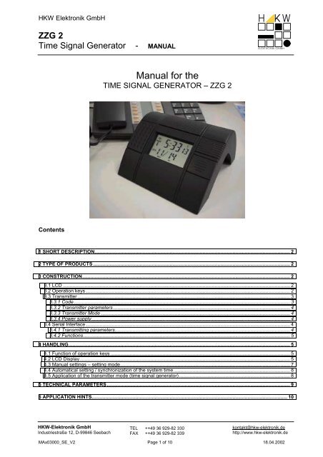
ZZG 2<br />
Time Signal Generator - MANUAL<br />
Manual for the<br />
TIME SIGNAL GENERATOR – ZZG 2<br />
Contents<br />
1 SHORT DESCRIPTION............................................................................................................................................... 2<br />
2 TYPE OF PRODUCTS ................................................................................................................................................ 2<br />
3 CONSTRUCTION........................................................................................................................................................ 2<br />
3.1 LCD ...................................................................................................................................................................... 2<br />
3.2 Operation keys ..................................................................................................................................................... 2<br />
3.3 Transmitter ........................................................................................................................................................... 3<br />
3.3.1 Code.............................................................................................................................................................. 3<br />
3.3.2 Transmitter parameters ................................................................................................................................. 4<br />
3.3.3 Transmitter Mode .......................................................................................................................................... 4<br />
3.3.4 Power supply................................................................................................................................................. 4<br />
3.4 Serial Interface ..................................................................................................................................................... 4<br />
3.4.1 Transmitting parameters................................................................................................................................ 4<br />
3.4.2 Functions....................................................................................................................................................... 5<br />
4 HANDLING.................................................................................................................................................................. 5<br />
4.1 Function of operation keys ................................................................................................................................... 5<br />
4.2 LCD Display.......................................................................................................................................................... 5<br />
4.3 Manual settings – setting mode............................................................................................................................ 7<br />
4.4 Automatical setting / synchronization of the system time..................................................................................... 8<br />
4.5 Application of the transmitter mode (time signal generator)................................................................................. 8<br />
5 TECHNICAL PARAMETERS...................................................................................................................................... 9<br />
6 APPLICATION HINTS............................................................................................................................................... 10<br />
<strong>HKW</strong>-<strong>Elektronik</strong> <strong>GmbH</strong><br />
Industriestraße 12, D-99846 Seebach<br />
TEL ++49 36 929-82 330<br />
FAX ++49 36 929-82 339<br />
kontakt@hkw-elektronik.de<br />
http://www.hkw-elektronik.de<br />
MAx03000_SE_V2 Page 1 of 10 18.04.2002
1 <strong>Short</strong> <strong>description</strong><br />
The ZZG2 is a battery powered LCD-clock which is able to display hours : minutes : seconds and the date. As a<br />
special feature the clock can simulate codes of different time-signals and can transmit these generated signals with a<br />
special internal ferrit antenna. Additionally the ZZG2 is able to communicate with microcontroller modules of type MCM<br />
RS232.<br />
According to these features the ZZG2 can be used as:<br />
support of RF-clocks in showrooms where you can’t receive the original time-signal<br />
support of RF-clocks outside the receiving area of original transmitter<br />
to convert the time-signal (support of RF-clocks through other transmitters)<br />
table clock<br />
2 Type of products<br />
In function of the requested code of time-signal and of its transmitting- (carrier-) frequency the ZZG2 can be offered in<br />
the following versions:<br />
Description<br />
code of time-signal / carrier frequency<br />
Simulator USA<br />
WWVB / 60 kHz<br />
Simulator DCF DCF / 77.5 kHz<br />
Simulator MSF MSF / 60 kHz<br />
3 Construction<br />
3.1 LCD<br />
hours<br />
minutes<br />
To indicate the<br />
status of<br />
transmitter<br />
mode<br />
Time zone<br />
seconds<br />
To indicate the setting mode for<br />
changing DST OFF " DST ON<br />
DATE in clock-mode and<br />
DAY for changing DST ON !" DST OFF in<br />
transmitter mode<br />
To indicate the setting mode for<br />
changing DST ON " DST OFF<br />
3.2 Operation keys<br />
Time-signal ON/OFF<br />
MODE<br />
adjust +<br />
adjust -<br />
to switch the transmitter mode ON/OFF<br />
to change the display-mode and the operation-mode<br />
to enlarge the display value in the adjust- (setting-) mode<br />
to reduce the display value in the adjust- (setting-) mode<br />
Time-signal ON / OFF<br />
M<br />
O<br />
D<br />
E<br />
adjust<br />
+<br />
adjust<br />
-<br />
MAx03000_SE_V2 Page 2 of 10<br />
18.04.2002
3.3 Transmitter<br />
3.3.1 Code<br />
In function of the selected ZZG2-version there can be simulated the time signals of the following transmitting stations:<br />
3.3.1.1 DCF<br />
DCF<br />
MSF<br />
WWVB<br />
The simulated DCF-signal includes the complete time-, check- and status-information like the original German time<br />
signal transmitter DCF77. The content of bit-positions of the 15 th to the 20 th second are fixed as follows:<br />
Second<br />
content<br />
15 always 0<br />
16 announcement for the coming change: summer-time (DST ON) !" winter-time (DST OFF)<br />
bit “A1”<br />
17 =0 for MEZ; =1 for MESZ bit “Z1”<br />
18 =1 for MEZ; =0 for MESZ bit “Z2”<br />
19 always 0<br />
20 always 1<br />
The change from winter- (DST OFF; MEZ) to summer-time (DST ON; MESZ) and reverse will be done automatically at<br />
that time specified before in the corresponding setting mode. The corresponding bit-positions which belong to this<br />
information will be changed accordingly. Please also refer to the attached application hints (chapter 6).<br />
3.3.1.2 MSF<br />
The simulated MSF-signal includes all time-information and check-bits like the original British time signal transmitter<br />
MSF. The Fast-Code wouldn’t be simulated. Special data bits are coded as follows:<br />
Second<br />
content<br />
1 ÷16 always 0 (double impulse)<br />
53 announcement for the coming change to summer-time (DST ON)<br />
58 =1; if standard time (DST OFF) bit “BST”<br />
=0; if summer-time (DST ON)<br />
The change from winter- (DST OFF) to summer-time (DST ON) and reverse will be done automatically at that time<br />
specified before in the corresponding setting mode. The corresponding bit-positions which belong to this information<br />
will be changed accordingly. Please also refer to the attached application hints (chapter 6).<br />
3.3.1.3 WWVB<br />
The simulated WWVB-Signal works like the original US time-signal respecting the fact that some of the included bits<br />
are always constant.<br />
Second<br />
content<br />
35, 36, 37 UT1 all bits = 0<br />
41 ÷ 44 UT1 Set all bits = 0<br />
56 Leap Second = 0<br />
The change from winter- (DST OFF) to summer-time (DST ON) and reverse will be done automatically at that time<br />
specified before in the corresponding setting mode. The corresponding bit-positions which belong to this information<br />
will be changed accordingly.<br />
MAx03000_SE_V2 Page 3 of 10<br />
18.04.2002
3.3.2 Transmitter parameters<br />
Modulation<br />
The AM-modulation (amplitude modulation) of the carrier frequency of all stations (DCF, MSF, WWVB) is different.<br />
Accuracy<br />
The accuracy of the clock is internally tuned by a trimmable capacitor in order to guarantee a tolerance of ≤1 sec. per<br />
day (T=20°C; constant). There is used a crystal for the time base. The temperature dependence of that crystal should<br />
be taken into account. Depending on the requirement we recommend to check the accuracy of internal time base in<br />
constant intervals.<br />
The difference between consecutive second impulses is 3 sec.) of the button „TIME SIGNAL ON/OFF“<br />
starts the transmitter to work permanently. The tower-icon is statical shown in the LCD (left upper corner). The<br />
time-signal is continuousely transmitted.<br />
In both operation modes the active mode of transmitter can be switched OFF by a short push of the button „TIME<br />
SIGNAL ON/OFF“.<br />
3.3.4 Power supply<br />
The ZZG2 can be powered or by the internal system battery (2*LR6; AA-size) or by a separate, external plug-in power<br />
supply. Using batteries, the ZZG2 can run in its clock-mode for about 1 year (Transmitter switched OFF!).<br />
To extend the operation-time of the ZZG2 we recommend the use of an external power supply which has to be<br />
connected to the provided DC-socket. By this way can be increased also the power of the transmitted time signal<br />
(transmitter ON). It will be about 70% higher than in battery-supply mode.<br />
Technical specification of external power supply:<br />
Voltage: 9V ÷12V DC<br />
Current: ≥ 150mA<br />
Connector: chinch (GND outside)<br />
inside dimension:<br />
outside dimension:<br />
length:<br />
2.1 mm<br />
5.5 mm<br />
11 mm<br />
3.4 Serial Interface<br />
3.4.1 Transmitting parameters<br />
Baud rate:<br />
300 baud<br />
Data bits: 8<br />
Stop bits: 2<br />
Parity:<br />
not considered<br />
Content of data-bits: please refer to the descprition of serial protocol of the MCM RS232 module<br />
MAx03000_SE_V2 Page 4 of 10<br />
18.04.2002
3.4.2 Functions<br />
By use of the serial interface the ZZG2-clock can be synchronized by another radio-controlled clock (for example MCM<br />
RS232) supporting the same serial interface and data protocol. The supplied time-information (included in the serial<br />
data protocol) will be tooked over once the ZZG2 is powered ON, at each full hour and after each manual setting of the<br />
ZZG2-clock. Applying this regular and automatic time synchronization the tolerance between the original time-signal<br />
and the generated time-signal (ZZG2 transmitter) can be kept 3 sec.)<br />
short push<br />
of the button<br />
long push<br />
of the button (>3 sec.)<br />
Adjust +<br />
Increments (+1) the<br />
selected value or moves<br />
it forward in the listing<br />
(step by step)<br />
Continuous Increment of<br />
the selected value<br />
Adjust -<br />
decrements (-1) the<br />
selected value or moves<br />
it backward in the listing<br />
(step by step)<br />
Continuous decrement of<br />
the selected value<br />
MODE<br />
to switch between<br />
display-modes:<br />
a) system time (internal<br />
time base) and<br />
b) transmitter data<br />
If pressed in<br />
display-mode a):<br />
• to enter the setting<br />
mode;<br />
an active transmitter is<br />
automatically switched<br />
OFF<br />
If pressed in<br />
display-mode b):<br />
• to switch between<br />
operation modes:<br />
b1) display of transmitter<br />
data and<br />
b2) generation and display<br />
of a test-pattern<br />
to select the next<br />
parameter<br />
Time<br />
Signal<br />
ON/OFF<br />
• to switch ON the<br />
transmitter for 10 min<br />
(temporary operation)<br />
• to switch OFF the<br />
transmitter in all<br />
modes if it was active<br />
before<br />
• to switch ON the<br />
transmitter<br />
(permanent operation)<br />
• to leave the setting<br />
mode;<br />
• the transmitter is<br />
automatically switched<br />
ON for 10 minutes<br />
(temporary operation)<br />
• to leave the setting<br />
mode;<br />
• the transmitter is<br />
automatically switched<br />
ON<br />
(permanent operation)<br />
4.2 LCD Display<br />
General display information:<br />
Upper digit-line: hours, minutes, seconds<br />
Lower digit-line: date<br />
Special symbols: AM, PM symbols to decide hours before noon (AM) and after noon (PM) in 12h<br />
time-display<br />
P,M,C,E time zones for the USA (Pacific, Mountain, Central, Eastern)<br />
radio tower shows the transmitter-status:<br />
OFF = transmitter is switched OFF<br />
ON = transmitter is switched ON (permanent operation)<br />
flashing = transmitter is switched ON for 10min. (temporary operation)<br />
MONTH active if the date is shown<br />
DAY<br />
active if the date is shown<br />
MAx03000_SE_V2 Page 5 of 10<br />
18.04.2002
Display during setting mode:<br />
Selected datas which can be modified by the keys “Adjust +” and/or “Adjust –“ will be displayed flashing.<br />
Special symbols:<br />
AL1<br />
AL2<br />
indicates the setting mode for datas specifying the change DST OFF (winter time) " DST ON<br />
(summer time)<br />
indicates the setting mode for datas specifying the change DST ON (summer time) " DST OFF<br />
(winter time)<br />
hours<br />
minutes<br />
To indicate the<br />
status of<br />
transmitter mode<br />
Time zone<br />
seconds<br />
To indicate the setting mode for<br />
changing DST OFF " DST ON<br />
DATE in clock-mode and<br />
DAY for changing DST ON !" DST OFF in<br />
transmitter mode<br />
To indicate the setting mode for<br />
changing DST ON " DST OFF<br />
Display mode of transmitter datas:<br />
Once the system-time is shown in the clock-mode the display-mode can be switched to transmitter-datas by a short<br />
push of the MODE-button.<br />
The digits in the lower LCD-line will indicate the type of simulated time-signal in function of the ZZG2-version.<br />
c) logical value of transmitted bit<br />
a) radio-tower flag<br />
seconds of system-time = bit-no.<br />
of transmitted data<br />
b) code of simulated time-signal<br />
to a)<br />
radio-tower flag shows the transmitter-status:<br />
OFF = transmitter is switched OFF<br />
ON = transmitter is switched ON (permanent operation)<br />
flashing = transmitter is switched ON for 10min. (temporary operation)<br />
to b):<br />
Code of simulated time-signal<br />
WWVB<br />
MSF<br />
DCF<br />
Display indicator<br />
USA<br />
MSF<br />
DCF<br />
to c) Each transmitted bit (second) having the logical value “1” is indicated by a short line. Bits of logical value “0”<br />
wouldn’t be shown. Their position will be kept free. Each new second-bit appears beside the tower-flag and<br />
moves then from left to rigth in 1 Hz rhythm.<br />
MAx03000_SE_V2 Page 6 of 10<br />
18.04.2002
4.3 Manual settings – setting mode<br />
You can enter the setting-mode by pressing the MODE-button >3s if the ZZG2 works in display-mode a) of the clockmode.<br />
An active transmitter is automatically switched OFF. During the setting mode it wouldn’t be transmitted any<br />
signal!<br />
All possible setting steps are shown in the following scheme:<br />
Display mode a)<br />
system time<br />
Adjust hours<br />
Adjust minutes<br />
Mode<br />
Adjust time zone<br />
Adjust year<br />
Mode > 3s<br />
Mode<br />
Mode<br />
Mode<br />
Adjust month<br />
Mode<br />
Adjust day<br />
Adjust the month of that point of time you want to change<br />
DST OFF (winter time) " DST ON (summer time)<br />
Mode<br />
Adjust the SUNDAY out of the selected month<br />
of that point of time you want to change<br />
DST OFF (winter time) " DST ON (summer time)<br />
Mode<br />
Adjust the month of that point of time you want to change<br />
DST ON (summer time) " DST OFF (winter time)<br />
Mode<br />
Adjust the SUNDAY out of the selected month<br />
of that point of time you want to change<br />
DST ON (summer time) " DST OFF (winter time)<br />
Display mode a)<br />
system time<br />
Mode<br />
NOTES:<br />
You can leave the setting mode at any time by pressing the button “Time Signal ON/OFF”. In the same time the<br />
transmitter is automatically switched ON.<br />
Once the minutes will be adjusted manually the seconds will be set to “00”. The clock will be re-started exactly<br />
once the „MODE“ -key is pressed afterwards.<br />
The points of time for changing DST ON (summer time) " DST OFF (winter time) and reverse are predefined by<br />
the software. It is possible to change these datas manually inside of the setting mode. You will have access to<br />
these DST- paramaters once all settings for the system-time were done.<br />
The point of time for DST-changings is always defined by the corresponding month and the corresponding<br />
Sunday out of the selected month. The setting range for the change “DST OFF (winter time) " DST ON (summer<br />
time)” allows the values March (3) …. Mai (5). The setting range for the change “DST ON (summer time) "<br />
DSTOFF (winter time)” allows the values Sept. (9) … Nov. (11). For each of these months can be selected the<br />
first, second, third, fourth or the last Sunday of the month.<br />
For each direction of DST-changing has to be specified one set of parameters. Two LCD-flags are used to<br />
indicate to which direction the current data belongs:<br />
AL1<br />
AL2<br />
indicates datas which specify the change “DST OFF (winter time)" DST ON (summer<br />
time)<br />
indicates datas which specify the change “DST ON (summer time)" DST OFF (winter<br />
time)<br />
Manually adjusted parameters for DST-changings will be lost by each POWER ON Reset !<br />
MAx03000_SE_V2 Page 7 of 10<br />
18.04.2002
4.4 Automatical setting / synchronization of the system time<br />
By use of the serial interface the ZZG2 can be connected to another radio-controlled clock supporting the same serial<br />
interface and data protocol. By this way the system time of the ZZG2 can be automatically synchronized to the time<br />
and date of the connected radio-controlled clock. Supposing that both units are connected to each other by a<br />
corresponding interface-cable, the supplied time-information (included in the serial data protocol) will be read in by the<br />
ZZG2 in the following situations:<br />
- once the ZZG2 is powered ON<br />
- at each full hour and<br />
- after each manual setting of the ZZG2-clock.<br />
Applying this regular and automatic time synchronization the tolerance between the original time-signal and the<br />
generated time-signal (ZZG2 transmitter) can be kept 3 sec.<br />
The power of the ZZG2-transmitter is strong enough to allow other radio controlled clocks/watches to receive the<br />
generated signal in a distance of up to 1... 5m around the transmitting unit.<br />
Transmitter-Power<br />
Field strength [ mV/m ]<br />
100,0<br />
90,0<br />
80,0<br />
70,0<br />
60,0<br />
50,0<br />
40,0<br />
30,0<br />
20,0<br />
10,0<br />
0,0<br />
1 1,5 2 2,5 3 3,5 4 4,5 5<br />
Distance [m]<br />
ext. power-supply<br />
battery<br />
for your reference:<br />
The field-strength of the DCF-signal measured<br />
at the <strong>HKW</strong>-location is about 6mV/m.<br />
MAx03000_SE_V2 Page 8 of 10<br />
18.04.2002
For a successful application of the ZZG2 please respect the following points:<br />
The diagramm shown above demonstrates the dependence of measured field strength in function of the distance<br />
to the ZZG2-transmitter. This diagramm represents the correct situation as long as the receiving antenna is in a<br />
parallel position to the transmitting antenna of the ZZG2-transmitter. If the antennas are in another position to<br />
each other then the field strength found by the receiving unit will be more weak.<br />
Radio controlled clocks/watches (units under test) which has to receive the time-signal transmitted by the ZZG2-<br />
transmitter have to be placed in a minimum distance to the ZZG2. The field strength found by the “unit under test”<br />
has to be ≤100 mV/m. If the field strength is to strong then the receiver can’t process the signal due to its<br />
overmodulation.<br />
To find the max. allowed distance between ZZG2 and the “unit under test” please put the receiving antenna into<br />
a parallel position to the transmitting antenna. There should be avoided any kind of electro-magnetical<br />
disturbances. They should be kept away in especially from the receiving unit.<br />
In case that more than one “unit under test” shall receive the transmitted signal in the same time then they should<br />
keep a minimum distance of about 20cm to each other (supposing a 2-dimensional placement).<br />
The operation distance (the transmitting and receiving range) will be reduced once the ZZG2 and/or the units<br />
under test will be placed on a metalic surface.<br />
If more than one ZZG2-transmitters are used in the same time and inside their transmitting range, then their<br />
transmitted signals will influence each other. It wouldn’t be possible to receive any accurate signal.<br />
Important:<br />
We recommend to switch ON the ZZG2-transmitter only as long as it is needed for the corresponding application.<br />
Otherwise there can appear overlapping problems with other signal-sources (for example on exhibitions).<br />
5 Technical parameters<br />
power supply:<br />
battery 2 x 1.5V, LR06, 2000mAh or<br />
battery 2 x 1.5V ,R06 zinc-coal, 1000mAh<br />
external power supply:<br />
Voltage:<br />
Current:<br />
Connector:<br />
current consumption:<br />
clock<br />
transmitter:<br />
9V ÷12V DC<br />
≥ 150mA<br />
chinch (GND outside)<br />
inside dimension:<br />
outside dimension:<br />
length:<br />
about 150...200µA<br />
about 100mA<br />
2.1 mm<br />
5.5 mm<br />
11 mm<br />
life time (battery-supply):<br />
clock only about. 1 year (transmitter OFF)<br />
transmitting mode about. 10 hours; transmitter ON (permanent operation)<br />
transmitting range:<br />
time accuracy:<br />
about. 5 m<br />
± 50ppm (T = 20°C; constant)<br />
short time tolerance of transmitted signal: ± 3ms (V1.4; measured at the emulator)<br />
carrier frequency of transmitted signal:<br />
tolerance of carrier frequency:<br />
77500Hz or 60000Hz<br />
± 100ppm<br />
modulation: WWVB -10dB<br />
DCF 25%<br />
MSF 0%<br />
Connector for the serial interface: modular jack / top entry / 6/6-poli Pin-configuration:<br />
1: GND<br />
2: RS232-OUT<br />
3: GND<br />
4: RS232-IN<br />
MAx03000_SE_V2 Page 9 of 10<br />
18.04.2002
6 Application hints<br />
The comportation of the simulated bits A1, Z1, Z2 (DCF77-protocol) and of the “announcement bit” and BST-bit (MSFprotocol)<br />
isn’t 100% compatible to the corresponding original time-code!<br />
Bit-status of original DCF77- (MSF-) time-code:<br />
Notation<br />
No. of second<br />
Summer time<br />
DST ON<br />
Winter time<br />
DST OFF<br />
A1 ( … ) announcement bit 16 (53) 0 0<br />
Z1 summer time bit 1 17 1 0<br />
Z2 (BST) summer time bit 2 18 (58) 0 1<br />
Real situtation of simulated DCF77- (MSF-) time-code:<br />
At the day of time-change “summer time !" winter time” the announcement bit A1 is transmitted with the logical<br />
value “1” starting with the protocol of the first minute.<br />
The announcement bit A1 will be set back (deleted) after the time-change “winter time " summer time” at 3:00<br />
o’clock.<br />
Example:<br />
Date Time A1 ( … ) Z1 Z2 (BST) Status / comment<br />
1. April 2000 23:59 0 0 1 Winter-time<br />
2. April 2000 00:00 1 0 1 Day of time-change to summer-time<br />
01:58 1 0 1<br />
01:59 1 0 1 Last minute of winter-time<br />
03:00 0 1 0 First minute of summer-time<br />
During the time-change “summer time " winter time” the corresponding bits wouldn’t be automatically set back<br />
to “winter-time”. The corresponding bits will be updated only once the manually setting-mode was entered or<br />
sometimes by switching ON/OFF the transmitter-signal.<br />
Example:<br />
Date Time A1 ( … ) Z1 Z2 (BST) Status / comment<br />
30. Sept. 2000 23:59 0 1 0 Summer-time<br />
01. Oct. 2000 00:00 1 1 0 Summer-time<br />
01:59 1 1 0 Summer-time<br />
02:00 1 1 0 Summer-time<br />
02:59 1 1 0 Summer-time<br />
02:00 1 1 0 Winter-time<br />
02:59 1 1 0 Winter-time<br />
03:00 1 1 0 Winter-time<br />
Winter-time<br />
06:06 0 0 1<br />
(bit-setting after starting the manually setting<br />
mode)<br />
Note:<br />
correct setting of the ZZG2 to simulate the time-change “summer time " winter time”:<br />
To simulate the time-change “summer time " winter time” the corresponding point of time can be manually set only in<br />
this way: 00:00 …. 2:59 o’clock summer time<br />
03:00 …. and later winter time<br />
To repeat the simulation of this time-change don’t use the decrement-function of the setting mode! You cannot reinstall<br />
the summer-time settings by changing hours backwards. Please change hours only forward by use of the<br />
increment function.<br />
MAx03000_SE_V2 Page 10 of 10<br />
18.04.2002