Grundlagen FlexRay - Institut für Automatisierungs- und ...
Grundlagen FlexRay - Institut für Automatisierungs- und ...
Grundlagen FlexRay - Institut für Automatisierungs- und ...

Create successful ePaper yourself
Turn your PDF publications into a flip-book with our unique Google optimized e-Paper software.
<strong>Gr<strong>und</strong>lagen</strong> <strong>FlexRay</strong> BasicsV 1.1 12<br />
A detailed overview of the requirements can be fo<strong>und</strong> in the <strong>FlexRay</strong> Requirements<br />
Specification V2.1 [FRRS05].<br />
Because of these properties, the <strong>FlexRay</strong> system is suited as a backbone, and for use in realtime<br />
and safety-critical applications.<br />
<strong>FlexRay</strong> is currently used in the BMW X5, BMW 7, Audi A8, and the new S-Class by<br />
Daimler [VeSc11].<br />
2 Technical basics<br />
2.1 OSI-Model<br />
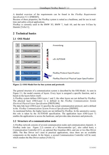
Figure 2.1 OSI-Model fort he bus system and protocols<br />
The general structure of a communication system is described by the OSI-Model. As seen in<br />
Figure 2.1, the model consists of layers. Every layer is assigned a specific function, and is<br />
based on the layers below itself.<br />
A <strong>FlexRay</strong> system defines OSI-Layers 1 and 2, the other layers are not defined by <strong>FlexRay</strong>.<br />
The physical layer (OSI-Layer 1) is defined in the <strong>FlexRay</strong> Communications System<br />
Electrical Physical Layer Specification [FREPLS06].<br />
The data link layer (OSI-Layer 2) specifies the actual communication protocol, and is defined<br />
in the <strong>FlexRay</strong> Communications System Protocol Specification [FRPS05].<br />
As mentioned before, the higher layers are not defined by <strong>FlexRay</strong>. In the automotive sector,<br />
this role is taken by the AUTOSAR specification. The application layer (OSI-Layer 7)<br />
enables the applications to access the hardware, and provides data structures and protocols.<br />
2.2 Structure of a communication node<br />
A <strong>FlexRay</strong> network consists of several communication nodes and communication channels. A<br />
<strong>FlexRay</strong> node (see Figure 2.2) consists of a Microcontroller (µC, also called host), a<br />
Communication Controller (CC), an optional Bus Guardian (BG), and one or two Bus Driver<br />
(BD). The Bus Driver isn’t used in practical applications, since there are no available<br />
components on the market. In the future, a second Communication Controller will be used,<br />
which renders the Bus Driver useless [VeSc11].<br />
Bäurle 12.10.2012