IRD 1010-e - Herrmann
IRD 1010-e - Herrmann
IRD 1010-e - Herrmann

You also want an ePaper? Increase the reach of your titles
YUMPU automatically turns print PDFs into web optimized ePapers that Google loves.
A Honeywell Company<br />
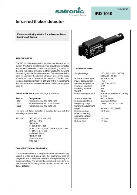
<strong>IRD</strong> <strong>1010</strong><br />
746e/08/98<br />
Infra-red flicker detector<br />
Flame monitoring device for yellow- or blueburning<br />
oil flames<br />
INTRODUCTION<br />
The <strong>IRD</strong> <strong>1010</strong> is employed to monitor the flame of an oil<br />
burner. This flame monitoring device should be connected<br />
to a Satronic oil burner control box. Monitoring is based on<br />
the infra-red flicker principle, in other words, the flickering<br />
infra-red light of the flame is detected. The steady radiation<br />
from, for example, the glowing refractory layer on the inside<br />
of the boiler, has no effect on the detector. The <strong>IRD</strong> <strong>1010</strong><br />
replaces the models <strong>IRD</strong> 910, 911 and 911 vi. If exchanging<br />
the units, care must be taken to connect them correctly (see<br />
page 3).<br />
TYPES AVAILABLE (also see page 4, Variants)<br />
Item no. Designation<br />
16501 Flicker detector <strong>IRD</strong> <strong>1010</strong> right<br />
16502 Flicker detector <strong>IRD</strong> <strong>1010</strong> end-on<br />
16503 Flicker detector <strong>IRD</strong> <strong>1010</strong> left<br />
The infra-red flicker detector is suitable for use with the<br />
following control boxes:<br />
<strong>IRD</strong> <strong>1010</strong> DKO 970, 972, 974, 976<br />
DKW 974, 976<br />
DMO 976<br />
TF 801, 802.1, 804<br />
TF 830.1, 832.1, 834.1, 834E.1, 834.2, 836<br />
TF 844, TF 974, 976<br />
MMD 900, 900.1,<br />
TTO 872, 876<br />
MMO 872, 876<br />
TMO 720-4<br />
TECHNICAL DATA<br />
Supply voltage 220 / 240 V (-15... +10%)<br />
50 Hz (50 - 60 Hz)<br />
Nominal current input approx. 4 mA<br />
Power consumption 1 VA<br />
Ambient temperature -20° C to +60° C<br />
Insulation standard IP 41<br />
Mounting attitude any<br />
Weight<br />
40 g<br />
Flame viewing attitude side-on or end-on according<br />
to type<br />
Spectral response 800 - 1100 nm<br />
(with daylight filter) maximum 950 nm<br />
Frequency range<br />
15 Hz.... 250 Hz (-12 dB)<br />
Sensitivity adjustment<br />
range<br />
approx. 1 : 20 (26 dB)<br />
Switch-on delay<br />
< 3.5 sec.<br />
(after connecting<br />
operating voltage)<br />
Response time<br />
< 0.1 sec.<br />
Cut-out time<br />
< 1 sec.<br />
CONSTRUCTIONAL FEATURES<br />
The infra-red sensor and the pre-amplifier are hermetically<br />
sealed in glass and along with the electronics form an<br />
integrated unit in the flame detector. Wiring is by way of a<br />
plug connection. The sensitivity control and two LED’s for<br />
indication of the flame signal are situated on the rear of the<br />
flicker detector.<br />
1
TECHNICAL FEATURES<br />
1. Flame detection<br />
- Yellow- as well as blue-burning oil flames can be monitored.<br />
- The flame detector is suitable for operation where the<br />
ambient temperature is within the range -20° to +60° C.<br />
- The flickering detector <strong>IRD</strong> <strong>1010</strong> becomes active not<br />
before a minimum threshold-level of steady light is<br />
exceeded. That guarantees that neither electromagneticnor<br />
ignition-spark noise are affecting the <strong>IRD</strong>.<br />
- Sensitivity is adjustable.<br />
- LED 1 is a warning indicator for the pre-purge phase as<br />
well as normal operation. LED 2 indicates the actual status<br />
of the detector: On or off.<br />
- During pre-purge, LED 1 indicates possible stray light,<br />
which may be produced either by a flickering or by<br />
a steady light source, before the detector switches on<br />
(LED 2).<br />
- When the burner is operating normally, LED 1 acts as a<br />
warning indication of the flame signal current sensitivity<br />
being set too low - it begins to flicker or extinguishes<br />
before the detector switches off.<br />
- The compact dimensions of the detector allow it to be<br />
installed on any burner. The detector shaft has the same<br />
dimensions as the FZ 711 S. It therefore also fits into the<br />
FZ holder M 74.<br />
- Unlike UV tubes, the <strong>IRD</strong> <strong>1010</strong> flicker detector does not<br />
deteriorate with age.<br />
2. Installation instructions<br />
- The detector probe should be fitted so that it receives the<br />
light which pulsates most strongly. This can be achieved<br />
by positioning the detector as close as possible to the<br />
flame or by directing it at a particular zone of the flame (e.g.<br />
by using a sighting tube).<br />
- No stray light must be allowed to fall on the detector (e.g.<br />
through cracks or from a sight glass). Pulsating stray light<br />
(e.g. from fluorescent lighting or light bulbs) could cause<br />
the system to switch to lockout. Due to the very high<br />
sensitivity of the detector, it should not be exposed<br />
directly or indirectly (reflections) to the ignition spark.<br />
- The infra-red flicker detector should be fitted in such a way<br />
that the ambient temperature cannot under any<br />
circumstances rise above 60 °C. At higher temperatures,<br />
there is a risk of incorrect operation and the life expectancy<br />
of the unit could be reduced. In addition, care should be<br />
taken that the detector is not subjected to unusually harsh<br />
vibration and receives no hard knocks.<br />
COMMISSIONING AND MAINTENANCE<br />
During commissioning and after servicing, the flame<br />
monitoring system should be checked for faultless operation<br />
as follows:<br />
1. Check that the detector is connected properly. Wrong<br />
connections are a risk to safety, and could cause damage<br />
to the detector unit or burner system.<br />
2. Adjust to maximum sensitivity and start the burner: If the<br />
LED indicator is lit after the start impulse, carefully adjust<br />
the sensitivity control until LED 1 extinguishes. No LED<br />
should light up during the pre-purge phase.<br />
3. With the system set for normal operation, pull out the<br />
detector probe and cover it up to cut off light. Both LED<br />
indicators must extinguish. The control box should switch<br />
to lockout or attempt to re-start the sequence.<br />
4. Attempt to re-start with the flame detector covered.<br />
There must be no indication from the LED’s after the start<br />
impulse. The burner control box must switch to lockout<br />
at the end of the safety interval.<br />
5. Attempt to start the burner with the detector exposed to<br />
stray light e.g. from fluorescent lighting, a cigarette<br />
lighter or light bulb (not daylight or an electric torch):<br />
Depending on the type of control box, it should switch to<br />
lockout either immediately or at the end of the pre-purge,<br />
as a result of stray light.<br />
6. When the burner is operating normally, carefully turn<br />
back the sensitivity control until LED 1 begins to flicker.<br />
Increase the setting again by one or two increments until<br />
both LED’s are lit. If LED 1 does not flicker even at position<br />
1: Leave potentiometer at position 1-2. This adjustment<br />
should be carried out when the flame signal current<br />
is weakest (shortly after flame establishment or after<br />
stabilisation).<br />
The flame detection device requires no maintenance of any<br />
kind, and as it is classed as safety equipment, no attempt<br />
should be made to open the housing.<br />
Because the nature of the flame can change in time due to<br />
the accumulation of dirt, the indicators on the detector<br />
should be checked periodically.<br />
Please note:<br />
Burner operating normally = both LED’s on<br />
Burner in pre-purge phase = both LED’s off<br />
For safety reasons the sensitivity must not be set<br />
higher than necessary.<br />
<strong>IRD</strong> <strong>1010</strong><br />
2
Possible faults<br />
1. LED’s light up during the pre-purge phase (control<br />
box switches to lockout):<br />
a) Sensitivity set too high<br />
b) Stray light<br />
c) Ignition spark visible to detector (directly or reflection).<br />
Correct by preventing direct sight of ignition spark.<br />
d) Interference from ignition cable (lay cables some<br />
distance apart, or possibly screen the detector).<br />
2. No indication from LED’s after establishment of flame:<br />
a) Incorrect or faulty wiring<br />
b) Sensitivity set too low<br />
c) Detector positioned wrongly (receives no light)<br />
d) Detector or viewing window dirty<br />
e) Defective detector<br />
<strong>IRD</strong> <strong>1010</strong> TERMINALS<br />
2<br />
1<br />
3<br />
4<br />
5<br />
6<br />
7<br />
1 2<br />
brown black blue<br />
CONNECTION OF <strong>IRD</strong> <strong>1010</strong> TO SATRONIC BURNER CONTROL BOXES<br />
Control box type TF 8.. TF 9.. DKO 9..<br />
DKW 9..<br />
DMO 9..<br />
<strong>IRD</strong> <strong>1010</strong><br />
blue<br />
black<br />
brown<br />
Terminal no. 2 7 2<br />
Terminal no. 1 1 1<br />
Terminal no. 9 9 9<br />
<strong>IRD</strong> <strong>1010</strong><br />
blue<br />
black<br />
brown<br />
Control box type MMD 900 TTO 872 MMO 872<br />
1)<br />
MMD 900.1 TTO 876 MMO 876<br />
Terminal no. 2 1 or 8 1 or 8<br />
Terminal no. 1 2 2<br />
Terminal no. 9 9 9<br />
1)<br />
<strong>IRD</strong> <strong>1010</strong><br />
blue<br />
black<br />
brown<br />
Control box type TMO 720-4<br />
Terminal no. 2<br />
Terminal no. 1<br />
Terminal no. 9<br />
1) By installing the <strong>IRD</strong>/TTO adaptor cable (Item no. 72002)<br />
between the <strong>IRD</strong> <strong>1010</strong> and the detector cable in conjunction<br />
with the TTO 8.. or MMO 8.. control boxes, the uniform<br />
system of baseplate wiring (blue = terminal 2, brown =<br />
terminal 9, black = terminal 1) can be adhered to.<br />
<strong>IRD</strong> <strong>1010</strong><br />
The standard-sensitive version of the <strong>IRD</strong> <strong>1010</strong> has a<br />
blue inprint. White or red inprints are marking detectors<br />
with special attributes.They may be used only on<br />
burners which are approved for these detectors.<br />
3
HOLDER M74<br />
35<br />
3<br />
FLICKER DETECTOR <strong>IRD</strong> <strong>1010</strong><br />
29 50 44<br />
ø 14<br />
4.5<br />
26<br />
21.8<br />
ø13.5<br />
ø20<br />
48<br />
4<br />
7<br />
104<br />
VARIANTS<br />
Light entrance from right Item no. 16501<br />
Satronic<br />
<strong>IRD</strong> <strong>1010</strong><br />
End-on light entrance Item no. 16502<br />
Satronic<br />
<strong>IRD</strong> <strong>1010</strong><br />
Light entrance from left Item no. 16503<br />
Satronic<br />
<strong>IRD</strong> <strong>1010</strong><br />
ORDERING INFORMATION<br />
ITEM DESIGNATION ITEM NO.<br />
Flame sensor Flicker detector <strong>IRD</strong> <strong>1010</strong> right 16501<br />
optional Flicker detector <strong>IRD</strong> <strong>1010</strong> end-on 16502<br />
optional Flicker detector <strong>IRD</strong> <strong>1010</strong> left 16503<br />
Mounting flange Holder M74 59074<br />
Connectioncable Plug type, 3 core cable, 0.6 m with tag wire ends 7236001<br />
The above ordering information refers to the standard version.<br />
Special versions are also included in our product range.<br />
Specifications subject to change without notice.<br />
<strong>IRD</strong> <strong>1010</strong><br />
4<br />
A Honeywell Company<br />
Satronic AG<br />
Honeywell-Platz 1<br />
Postfach 324<br />
CH-8157 Dielsdorf