Materials and Structures for Aerospace Propulsion Systems ...
Materials and Structures for Aerospace Propulsion Systems ...
Materials and Structures for Aerospace Propulsion Systems ...

You also want an ePaper? Increase the reach of your titles
YUMPU automatically turns print PDFs into web optimized ePapers that Google loves.
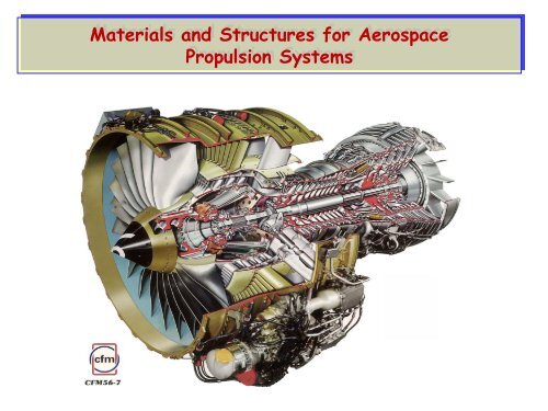
<strong>Materials</strong> <strong>and</strong> <strong>Structures</strong> <strong>for</strong> <strong>Aerospace</strong><br />
<strong>Propulsion</strong> <strong>Systems</strong>
Scramjets<br />
Rocket<br />
X-43b<br />
Aeroturbine<br />
Image courtesy of ATK
High By-pass Aeroturbine
Air flow<br />
http://www.aip.org/tip/INPHFA/vol-10/iss-4/p24.html<br />
Scramjets integrate air <strong>and</strong> space by Dean Andreadis
Efficiency of Various <strong>Propulsion</strong> Cycles:<br />
Specific Impulse (Thrust/weight)<br />
8000<br />
Hydrogen Fuel<br />
Hydrocarbon Fuels<br />
I sp<br />
6000<br />
4000<br />
Turbojets<br />
Ramjets<br />
Rocket<br />
RBCC<br />
TBCC<br />
2000<br />
Turbojets<br />
Ramjets<br />
Scramjets<br />
Scramjets<br />
Rockets<br />
0<br />
0 10 20<br />
MACH NUMBER
Specific Fuel Consumption <strong>for</strong> Various Concepts<br />
10<br />
9<br />
Conventional Rocket<br />
8<br />
7<br />
TSFC (Lbm/Lbf/Hr.)<br />
6<br />
5<br />
4<br />
3<br />
Turbine Engines<br />
Ramjet Take Over<br />
Scram/Rocket<br />
Rocket Off<br />
2<br />
1<br />
Ram/Scram Operation<br />
0<br />
0 1 2 3 4 5 6 7 8 9 10 11 12<br />
Hydrogen Fuel<br />
Flight Mach Number
Fuel Efficiency In the Aero-turbine Industry:<br />
JT3C<br />
Turbojet<br />
Low Bypass<br />
Turbofan<br />
High Bypass<br />
Turbofan<br />
2 nd Gen High Bypass<br />
Turbofan<br />
JT3D-1<br />
CJ805<br />
JT8D-9<br />
Specific Fuel<br />
consumption<br />
JT9D-7A<br />
JT8D-217<br />
TAY 620<br />
JT9D-3A<br />
CFM56-2<br />
CF6-6D RB-211-524D<br />
V2500 A1 CFM56-5A<br />
BR 715<br />
JT9D-7R4G2<br />
CF6-80A RB-211-535E4 CF6-80C2-B6F<br />
PW2037<br />
CFM56-5C4<br />
PW4056<br />
CF6-80E1-A2<br />
PW4168 PW4098<br />
PW4084<br />
TRENT 895<br />
GE90-85B<br />
GE90-115B<br />
R. SHAFRICK, GE Aircraft Engines<br />
1950 1960 1970 1980 1990 2000 2010 2020<br />
Certification Date
Engine Temperature Trend<br />
GE90-115B<br />
Gas Temperature, FRT<br />
TF33<br />
CF6-50E<br />
CFM56-5C4 GE90-90B<br />
CFM56-5B<br />
Trent 772<br />
CFM56-5C2<br />
GE90-94B<br />
Trent 892<br />
Trent 556<br />
PW 4090<br />
CF34-10<br />
V2533 CFM56-7B<br />
CFM56-3C<br />
PW 6024<br />
BR 715<br />
CF6-50E2 PW 2037<br />
CF6-80E1<br />
CF6-80C2A5 PW 4062<br />
CF34-8C1<br />
CF6-80A3<br />
CFM56-2B<br />
CF6-80C2D1F<br />
CFM56-5A<br />
BR 710<br />
CF6-80C2B1F<br />
JT9D<br />
CF34-3A<br />
CF34-3B<br />
CFM56-3B2<br />
CF6-80C2A1<br />
CFM56-3B1<br />
JT8D-219<br />
RB 211<br />
62 64 66 68 70 72 74 76 78 80 82 84 86 88 90 92 94 96 98 00 02 04 06 08 10 12<br />
Engine Certification Date
Role of Airfoil <strong>Materials</strong><br />
CMCs<br />
Increased<br />
Temperature<br />
Capability(K)<br />
1600<br />
1300<br />
1000<br />
GEN2<br />
GEN1<br />
Advanced Thermal Barrier <strong>Systems</strong><br />
GEN3<br />
GEN4<br />
Superalloys<br />
1985 1990 1995 2000 2005<br />
Introduction Date<br />
Turbine Airfoil Material Advancements
Specific Strengths of Metallic <strong>Systems</strong><br />
Superalloys &<br />
Refractories
More High Temperature <strong>Materials</strong>
Role of Airfoil <strong>Materials</strong><br />
CMCs<br />
Increased<br />
Temperature<br />
Capability(K)<br />
1600<br />
1300<br />
1000<br />
GEN2<br />
GEN1<br />
Advanced Thermal Barrier <strong>Systems</strong><br />
GEN3<br />
GEN4<br />
Superalloys<br />
1985 1990 1995 2000 2005<br />
Introduction Date<br />
Turbine Airfoil Material Advancements
Superalloy Turbine Air Foils<br />
Equiaxed (EQ) Dir. Sol. (DS) Single Xtal (SX)
Ni Superalloy Improvements<br />
1020<br />
Temperature Capability - °C<br />
1000<br />
980<br />
960<br />
940<br />
920<br />
900<br />
880<br />
Ρ80<br />
Ρ125<br />
Ρ80Η<br />
Ν4<br />
Ρ142<br />
Ν5<br />
Ν6<br />
ΜΞ4<br />
860<br />
840<br />
1969 1972 1982 1984 1988 1989 1994<br />
Year of Introduction<br />
2000<br />
ASM-TMS NY042198 16
Modeling at the scale of the grains<br />
Single crystal turbine<br />
blade
Role of Airfoil <strong>Materials</strong><br />
CMCs<br />
Increased<br />
Temperature<br />
Capability(K)<br />
1600<br />
1300<br />
1000<br />
GEN2<br />
GEN1<br />
Advanced Thermal Barrier <strong>Systems</strong><br />
GEN3<br />
GEN4<br />
Superalloys<br />
1985 1990 1995 2000 2005<br />
Introduction Date<br />
Turbine Airfoil Material Advancements
Airfoil Technology<br />
Airfoil Technology<br />
Heat<br />
Transfer<br />
High Per<strong>for</strong>mance Coating <strong>Systems</strong>:<br />
Enabling technology <strong>for</strong> advanced gas turbines
Transverse Section
Al Reservoir<br />
Thermal Barrier Multilayer
Nanoscale Porosity
Deposition Effects on Microstructure<br />
Deposition Effects on Microstructure<br />
Airfoil Mode<br />
Plat<strong>for</strong>m Mode
Interplay with<br />
Component<br />
Geometry<br />
20 µm<br />
• Reduced coating thickness within recess,<br />
quantitatively consistent with reduction<br />
in integrated flux due to shadowing by<br />
corners.<br />
• Reduced inter-columnar gap width—<strong>and</strong><br />
increased propensity to sintering—due<br />
to elimination of most oblique vapor flux.<br />
2 µm<br />
5 µm
Role of Airfoil <strong>Materials</strong><br />
CMCs<br />
Increased<br />
Temperature<br />
Capability(K)<br />
1600<br />
1300<br />
1000<br />
GEN2<br />
GEN1<br />
Advanced Thermal Barrier <strong>Systems</strong><br />
GEN3<br />
GEN4<br />
Superalloys<br />
1985 1990 1995 2000 2005<br />
Introduction Date<br />
Turbine Airfoil Material Advancements
Ceramic Matrix Composites (CMC)<br />
CMC Combustor Liner<br />
Cooling Air Reduction<br />
Weight Reduction<br />
20% NOx Reduction<br />
CMC Vane<br />
CMC Blade<br />
Weight Reduction<br />
Reduced Cooling Air<br />
Increased Efficiency<br />
CMC’s Reduce Weight <strong>and</strong> Improve Per<strong>for</strong>mance
(MI) SiC/SiC (DENSE MATRIX)<br />
T = 1400C (Metals < 1100C)<br />
‣High Thermal Conductivity<br />
‣Inter-laminar Shear Strength<br />
‣Reduced Sensitivity to Pesting
Transition duct<br />
Nozzles<br />
Integrally woven<br />
CMC <strong>Structures</strong><br />
Alumina anchor tube in<br />
CMC skin <strong>for</strong> pin joint<br />
Braided SiC/SiC<br />
Hyper-Therm Inc.<br />
Metallic struts<br />
with CMC skin
Angle Interlock<br />
Sylramic/SiC<br />
±45°
CMC Combustor<br />
Liners<br />
<br />
<br />
<br />
<br />
Hi-Nicalon, Slurry Cast<br />
Successful Engine Testing<br />
Pre <strong>and</strong> Post Engine Test NDE<br />
Revealed Degradation<br />
Additional Engine Testing<br />
CMC Inner Combustor Liner After Engine Testing<br />
CMC Combustor Liner Rig & Engine Testing Successful
CMC Applications in Utility Gas Turbines<br />
Benefits:<br />
• NOx reductions (50%)<br />
• CO reductions (50%)<br />
• Improved stability<br />
• Life improvement<br />
Annular Combustors<br />
Shroud<br />
Segments<br />
Benefits:<br />
• 90% cooling air reduction<br />
• 0.2% efficiency gain<br />
• Reduced tip clearance<br />
These efficiency,<br />
power, <strong>and</strong> emissions<br />
benefits translate to<br />
$M in annual savings<br />
<strong>for</strong> each installation.<br />
Benefits:<br />
• >90% cooling air reduction<br />
• 0.4% efficiency gain<br />
• Cost savings over SOA technology<br />
Vanes<br />
Benefits:<br />
• 90% cooling air reduction<br />
• Efficiency gains of >1%<br />
• NOx reductions (50%)
Hybrid CMC Concept<br />
The "hybrid" concept involves use of a moderate temperature (~1100° -<br />
1200°C) CMC structural member bonded to a ceramic insulating material<br />
having good stability at 1600°C <strong>and</strong> good erosion resistance.<br />
Hot Face Temp<br />
1600°C<br />
Ceramic<br />
Adhesive<br />
Bond Line<br />
Temp.<br />
1100°C<br />
FGI Insulation Layer<br />
Structural CMC<br />
~3mm<br />
~4mm<br />
Cold Face Temp<br />
750°C<br />
• Oxide fiber available<br />
• Insulating material technology available<br />
• Reduces cooling needs drastically
Role of Airfoil <strong>Materials</strong><br />
SiC/SiC CMCs<br />
Increased<br />
Temperature<br />
Capability(K)<br />
1600<br />
1300<br />
1000<br />
GEN2<br />
GEN1<br />
Advanced Thermal Barrier <strong>Systems</strong><br />
GEN3<br />
GEN4<br />
Superalloys<br />
1985 1990 1995 2000 2005<br />
Introduction Date<br />
Turbine Airfoil Material Advancements
Thermal Barrier Multilayer:<br />
Challenging Thermo-Chemo-Mechanical System
Thermal Property Interplay
RESIDUAL STRESS IN TGO
Thermal Property Interplay<br />
Slide 24
Thermal Barrier Multilayer:<br />
Challenging Thermo-Chemo-Mechanical System
YSZ Compatibility with TGO<br />
YSZ Compatibility with TGO<br />
EB-PVD on FeCrAlY substrate<br />
1200°C<br />
TGO<br />
TGO<br />
Zirconate<br />
reactive<br />
with TGO<br />
Limit of thermochemical<br />
compatibility ~21%YO 1.5<br />
After As Deposited 100h at 1200°C<br />
7YSZ compatible with TGO<br />
(no inter-phases <strong>for</strong>med)<br />
1 µm
Degradation Modes In Engines<br />
Delay Spalling By Underst<strong>and</strong>ing<br />
Mechanisms<br />
And Adjusting Constituent<br />
Properties<br />
80%<br />
Impact<br />
Damage<br />
TBC spallation<br />
TBC<br />
spallation<br />
40%<br />
1820 engine cycles
Step I:Identify All Mechanisms Limiting Durability<br />
Step I:Identify All Mechanisms Limiting Durability<br />
Step II: Develop Models that Relate Durability to Material Properties
Example I (Intrinisc): Failure by TGO Rumpling<br />
Example I (Intrinisc): Failure by TGO Rumpling<br />
• Strain misfits cause cyclic<br />
stresses that motivate<br />
cycle-by-cycle crack<br />
growth in TBC<br />
• Highly non-linear:<br />
. Requires numerical code<br />
• Phenomena include TGO<br />
lateral growth, thermal<br />
expansion misfit<br />
(martensite), cyclic<br />
plasticity.<br />
Swelling<br />
Martensite
Fails at Oxide/Oxide Interface<br />
LARGE SCALE BUCKLE: THE END OF LIFE<br />
•WHAT HAPPENED EARLIER?
DISPLACEMENT INSTABILITY<br />
Multi-Parameter Phenomenon:<br />
Relevant Phenomena:<br />
•Elongation/Thickening of TGO<br />
•Plastic Flow of Bond Coat<br />
•Strain Misfit of Bond Coat<br />
Need Model<br />
Plus<br />
Critical Experiments<br />
DESCRIBE CONJOINTLY
OBJECTIVE: DEVISE MECHANISM MAPS THAT SPECIFY SALIENT<br />
NON-DIMENSIONAL PARAMETERS
UNDERSTAND THE FUNDAMENTALS<br />
TGO
De<strong>for</strong>mation Mechanism Map<br />
Synchotron Measurements
Synchotron Measurements
•Thermal Expansion<br />
•Martensite<br />
•Swelling<br />
‣ “Soften” Bond Coat
STRAIN MISFITS: MARTENSITE TRANSFORMATION<br />
L1 0<br />
600C<br />
41 42 43 44 45 46 47 48 49<br />
B2<br />
650C<br />
41 42 43 44 45 46 47 48 49
VALIDATION Model EXPERIMENTS: Validation: Example AN EXAMPLE<br />
1. Elastic properties of constituents<br />
2. Thermal expansion mismatch between layers.<br />
3. Power-law creep.<br />
4. Reversible phase trans<strong>for</strong>mation in bond coat.<br />
5. Growth stress in TGO.<br />
6. Thickening <strong>and</strong> lateral growth strain in the TGO<br />
7. Initial Interface Imperfections
ANIMATION OF TGO DISTORTION AND ELONGATION<br />
QuickTime <strong>and</strong> a<br />
GIF decompressor<br />
are needed to see this picture.
Model<br />
Validation:<br />
Transition<br />
to GE<br />
Balint-Hutchinson Code<br />
TGO<br />
BC<br />
Substrate<br />
Code now in use at GE
SENSITIVITY STUDY USING MECHANISM MAP:<br />
CAN MECHANISM BE SUPPRESSED?
USE MECHANISM MAP TO ELIMINATE RATCHETING<br />
Interface Toughness<br />
Becomes Key<br />
Parameter:
NEW INTERFACE<br />
TOUGHNESS TEST<br />
G side<br />
= 1 2 S ⎛ π δ⎞<br />
⎝ 4 b⎠<br />
4<br />
⎛<br />
+2D π ⎞<br />
⎝ b⎠<br />
2 π<br />
⎛ δ⎞<br />
⎝ 4 b⎠<br />
2<br />
f=0.26<br />
f=1.0<br />
Γ = 20Jm -2
Mode I Adhesion Energy<br />
of Metal / Alumina Interfaces
Work of Separation: Ni/Al 2 O 3 interfaces<br />
Expt.<br />
TBC Ni(Al)/Al 2 O 3 interface:<br />
Fracture at interface<br />
Mode I toughness ~ 20 J/m 2<br />
Pure Ni/Al 2 O 3 interface:<br />
Fracture in Alumina<br />
Mode I toughness > 300 J/m 2<br />
Theo.<br />
3.79 J/m 2<br />
6.84 J/m 2 3.25 J/m 2<br />
1.30J/m 2 Al-termination O-termination
Delay Spalling<br />
By Underst<strong>and</strong>ing<br />
Mechanisms<br />
And<br />
Adjusting Constituent<br />
Properties<br />
Failure Modes After Engine Test
Two Basic Erosion <strong>and</strong> FOD Mechanisms<br />
Two Basic Erosion <strong>and</strong> FOD Mechanisms<br />
I:Elastodynamic<br />
50µm<br />
II:Viscoplastic<br />
50µm
Viscoplastic Domain<br />
QuickTime <strong>and</strong> a<br />
BMP decompressor<br />
are needed to see this picture.<br />
4<br />
LE Simulations<br />
Soft at High Temperature
Erosion Threshold Map<br />
Erosion Threshold Map<br />
ELASTO-<br />
DYNAMIC<br />
DOMAIN<br />
Identify Importance of<br />
Material Properties:<br />
‣High Toughness<br />
‣Soft at High Temperature