IC-R9500 Manual - ICOM Canada
IC-R9500 Manual - ICOM Canada
IC-R9500 Manual - ICOM Canada

You also want an ePaper? Increase the reach of your titles
YUMPU automatically turns print PDFs into web optimized ePapers that Google loves.
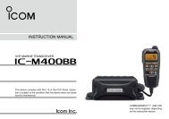
COMMUN<strong>IC</strong>ATIONS RECEIVER<br />
i<strong>R9500</strong><br />
Instruction <strong>Manual</strong><br />
A-6553H-1EX<br />
Printed in Japan<br />
© 2007 Icom Inc.
FOREWORD<br />
Thank you for making the <strong>IC</strong>-<strong>R9500</strong> your radio of choice. We hope you<br />
agree with Icom’s philosophy of “technology first.” Many hours of research<br />
and development went into the design of your <strong>IC</strong>-<strong>R9500</strong>.<br />
D FEATURES<br />
❍ Ultimate receiver performance: 109 dB wide dynamic range<br />
and third-order intercept (IP3) of +40 dBm (HF bands only)<br />
❍ 7-inch wide color TFT LCD<br />
❍ Built-in Baudot FSK demodulator<br />
❍ High resolution spectrum scope— center frequency and fix<br />
frequency modes, plus mini-scope displays<br />
IMPORTANT<br />
READ THIS INSTRUCTION MANUAL CAREFULLY before attempting<br />
to operate the receiver.<br />
SAVE THIS INSTRUCTION MANUAL. This manual contains important<br />
safety and operating instructions for the <strong>IC</strong>-<strong>R9500</strong>.<br />
EXPL<strong>IC</strong>IT DEFINITIONS<br />
WORD<br />
R WARNING<br />
CAUTION<br />
NOTE<br />
DEFINITION<br />
Personal injury, fire hazard or electric shock may<br />
occur.<br />
Equipment damage may occur.<br />
If disregarded, inconvenience only. No risk of personal<br />
injury, fire or electric shock.<br />
TRADEMARKS<br />
Icom, Icom Inc. and the logo are registered trademarks of Icom<br />
Incorporated (Japan) in the United States, the United Kingdom, Germany,<br />
France, Spain, Russia and/or other countries.<br />
ABOUT RE-EXPORTING THIS PRODUCT:<br />
If re-exporting this product, it is your responsibility to check you are in compliance with the export regulations<br />
of your country or the country you are exporting to. Export regulations can be highly restrictive in relation to<br />
some of the technology implemented in this product. Your failure to comply with export regulations may subject<br />
you to fines or penalties. Please consult with the relevant Government Department in your country.<br />
i
PRECAUTIONS<br />
R WARNING! NEVER operate the receiver with a<br />
headset or other audio accessories at high volume<br />
levels. Hearing experts advise against continuous high<br />
volume operation. If you experience a ringing in your<br />
ears, reduce the volume or discontinue use.<br />
R CAUTION! NEVER change the internal settings<br />
of the receiver. This may reduce receiver performance<br />
and/or damage to the receiver.<br />
The receiver warranty does not cover any problems<br />
caused by unauthorized internal adjustment.<br />
R CAUTION! The receiver weighs approx. 20 kg<br />
(44 lb). Always have two people available to carry, lift<br />
or turn over the receiver.<br />
R CAUTION! The line-voltage receptacle must be<br />
near the receiver and must be easily accessible. Avoid<br />
extension cords.<br />
The LCD display may have cosmetic imperfections that<br />
appear as small dark or light spots. This is not a malfunction<br />
or defect, but a normal characteristic of LCD<br />
displays.<br />
During maritime mobile operation, keep the receiver as<br />
far away as possible from the magnetic navigation<br />
compass to prevent erroneous indications.<br />
Turn [I/O] switch (on the rear panel) OFF and/or disconnect<br />
the AC power cable from the AC outlet when<br />
you will not use the receiver for a long period of time.<br />
For U.S.A. only<br />
CAUTION: Changes or modifications to this device,<br />
not expressly approved by Icom Inc., could void your<br />
authority to operate this device under FCC regulations.<br />
R ACHTUNG! Die Steckdose muß nabe bei<br />
diesem Gerät angebracht und zugänglich sein.<br />
R NEVER let metal, wire or other objects protrude<br />
into the receiver or into connectors on the rear panel.<br />
This may result in an electric shock.<br />
R NEVER block any cooling vents on the top, rear<br />
or bottom of the receiver.<br />
R NEVER expose the receiver to rain, snow or any<br />
liquids.<br />
R NEVER install the receiver in a place without adequate<br />
ventilation. Heat dissipation may be reduced,<br />
and the receiver may be damaged.<br />
R NEVER operate or touch the receiver with wet<br />
hands. This may result in an electric shock or damage<br />
to the receiver.<br />
DO NOT use chemical agents such as benzine or alcohol<br />
when cleaning the <strong>IC</strong>-<strong>R9500</strong>, as they can damage<br />
the receiver’s surfaces.<br />
AVOID using or storing the receiver in areas with temperatures<br />
below ±0°C (+32°F) or above +50°C<br />
(+122°F).<br />
AVOID placing the receiver in excessively dusty environments<br />
or in direct sunlight.<br />
AVOID placing the receiver against walls or putting<br />
anything on top of the receiver. This may overheat the<br />
receiver.<br />
Always place unit in a secure place to avoid inadvertent<br />
use by children.<br />
ABOUT APCO PROJECT 25<br />
This device made under license under one or more of<br />
the following US patents: #4,590,473, #4,636,791,<br />
#5,148,482, #5,185,796, #5,271,017, #5,377,229.<br />
The IMBE voice coding technology embodied in this<br />
product is protected by intellectual property rights<br />
including patent rights, copyrights and trade secrets of<br />
Digital Voice Systems, Inc. This voice coding<br />
Technology is licensed solely for use within this communications<br />
equipment. The user of this technology is<br />
explicitly prohibited from attempting to decompile,<br />
reverse engineer, or disassemble the object code, or<br />
in any other way convert the object code into a<br />
human-readable form. U.S. Pat. nos. #5,870,405,<br />
#5,826,222, #5,754,974, #5,701,390, #5,715,365,<br />
#5,649,050, #5,630,011, #5,581,656, #5,517,511,<br />
#5,491,772, #5,247,579, #5,226,084, #5,195,166.<br />
P25 digital mode is available when the optional<br />
UT-122 DIGITAL UNIT is installed.<br />
ii
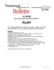
SUPPLIED ACCESSORIES<br />
q<br />
w<br />
e<br />
r<br />
(FH M4×16 mm)<br />
t y u i<br />
o<br />
!0<br />
!2<br />
(FH M4×12 mm)<br />
!1<br />
(PH M4×8 mm)<br />
FH: Flat head<br />
PH: Pan head<br />
(see p. 2-7 for installation details)<br />
q AC power cable* ………………………………… 1<br />
w Carrying handles ……………………………… 1 set<br />
e Spare fuse (FGB 1 A) …………………………… 1<br />
r Spare fuse<br />
FGB 4 A (100 V/120 V versions) ………………… 1<br />
0234002MXP (230 V/240 V versions) …………… 1<br />
t RCA plugs ………………………………………… 4<br />
y DC power plug …………………………………… 1<br />
u 2-conductor 1⁄8″ plugs …………………………… 7<br />
i 3-conductor 1⁄8″ plugs …………………………… 1<br />
o 8 pin ACC plugs …………………………………… 2<br />
!0 Screws for side plate † …………………………… 4<br />
!1 Hiding screws for screw hole † …………………… 2<br />
!2 Ferrite bead ‡ ……………………………………… 3<br />
*May differ from that shown according to version.<br />
†<br />
These screw are used when removing rack mounting handles.<br />
‡<br />
These are used when connecting cables to [DATA IN], [LAN]<br />
or [USB].<br />
iii
TABLE OF CONTENTS<br />
Section 1<br />
Section 2<br />
Section 3<br />
Section 4<br />
PANEL DESCRIPTION<br />
■ Front panel ……………………………………………………………… 1-2<br />
■ Rear panel ……………………………………………………………… 1-10<br />
■ LCD display …………………………………………………………… 1-12<br />
■ Screen menu arrangement …………………………………………… 1-14<br />
INSTALLATION AND CONNECTIONS<br />
■ Unpacking ……………………………………………………………… 2-2<br />
■ Selecting a location …………………………………………………… 2-2<br />
■ Grounding ……………………………………………………………… 2-2<br />
■ Antenna connection …………………………………………………… 2-3<br />
■ TV jumper cable connection …………………………………………… 2-4<br />
■ Carrying handle attachment …………………………………………… 2-4<br />
■ Rack mounting handle detachment …………………………………… 2-4<br />
■ Required connections ………………………………………………… 2-5<br />
D Rear panel …………………………………………………………… 2-5<br />
■ Advanced connections ………………………………………………… 2-6<br />
D Front panel …………………………………………………………… 2-6<br />
D Rear panel—1 ……………………………………………………… 2-6<br />
D Rear panel—2 ……………………………………………………… 2-7<br />
■ Tape recorder connections …………………………………………… 2-8<br />
D Recording from the front panel or rear panel …………………… 2-8<br />
D Separately recording audio and frequency ……………………… 2-9<br />
■ Monitor display connection …………………………………………… 2-10<br />
■ Transceive function …………………………………………………… 2-10<br />
■ FSK and AFSK (SSTV) connections ………………………………… 2-11<br />
■ Accessory connector information …………………………………… 2-12<br />
BAS<strong>IC</strong> OPERATIONS<br />
■ When first applying power (CPU resetting) ………………………… 3-2<br />
■ Initial settings …………………………………………………………… 3-2<br />
■ Selecting VFO mode …………………………………………………… 3-3<br />
■ Selecting memory mode ……………………………………………… 3-3<br />
■ Frequency setting ……………………………………………………… 3-4<br />
D Direct frequency entry with the keypad …………………………… 3-4<br />
D Tuning with the main dial …………………………………………… 3-5<br />
D Selecting a tuning step ……………………………………………… 3-5<br />
D Auto tuning step function …………………………………………… 3-6<br />
D 1⁄4 tuning step function ……………………………………………… 3-6<br />
■ Operating mode selection ……………………………………………… 3-7<br />
■ Volume setting ………………………………………………………… 3-8<br />
■ RF gain adjustment …………………………………………………… 3-8<br />
■ Squelch level adjustment ……………………………………………… 3-8<br />
■ Audio tone adjustment ………………………………………………… 3-9<br />
D Treble level adjustment ……………………………………………… 3-9<br />
D Bass level adjustment ……………………………………………… 3-9<br />
■ Meter indication selection …………………………………………… 3-10<br />
D Meter type selection ……………………………………………… 3-10<br />
RECEIVE MODES<br />
■ Operating FM …………………………………………………………… 4-2<br />
D Convenient functions for FM …………………………………………4-2<br />
■ Duplex operation ……………………………………………………… 4-3<br />
D Offset frequency setting ………………………………………………4-3<br />
iv
TABLE OF CONTENTS<br />
■ Tone/DTCS squelch operation ………………………………………… 4-4<br />
■ Operating WFM ………………………………………………………… 4-5<br />
D Convenient functions for WFM ………………………………………4-5<br />
■ Operating AM …………………………………………………………… 4-6<br />
D Convenient functions for AM …………………………………………4-6<br />
■ Operating SSB ………………………………………………………… 4-7<br />
D Convenient functions for SSB ………………………………………4-7<br />
■ Operating CW …………………………………………………………… 4-8<br />
D Convenient functions for CW ………………………………………4-8<br />
D APF (Audio Peak Filter) operation …………………………………4-9<br />
D About CW reverse mode ……………………………………………4-9<br />
D About CW pitch control ………………………………………………4-9<br />
■ Operating FSK ………………………………………………………… 4-10<br />
D Convenient functions for FSK ………………………………………4-11<br />
D About FSK reverse mode …………………………………………4-11<br />
D Twin peak filter ………………………………………………………4-11<br />
D Setting FSK tone frequency ………………………………………4-12<br />
D Functions for the FSK decoder indication …………………………4-13<br />
D Setting the decoder threshold level ………………………………4-13<br />
D FSK decode set mode ………………………………………………4-14<br />
D Setting FSK Baud rate ………………………………………………4-16<br />
D Time stamp function …………………………………………………4-16<br />
D Data saving …………………………………………………………4-17<br />
■ Operating P25 (Requires optional UT-122) ………………………… 4-18<br />
D Convenient functions for P25 ………………………………………4-18<br />
■ Digital squelch operation ……………………………………………… 4-19<br />
■ TV channel operation (except for USA version) …………………… 4-20<br />
D Convenient functions for TV operation ……………………………4-20<br />
Section 5<br />
RECEIVE FUNCTIONS<br />
■ Spectrum scope screen ……………………………………………… 5-2<br />
D Center mode ………………………………………………………… 5-2<br />
D Fix mode ……………………………………………………………… 5-3<br />
D Peak marker function ……………………………………………… 5-4<br />
D Wide band-pass filter selection……………………………………… 5-5<br />
D Wide band scope function …………………………………………… 5-5<br />
D Mini scope screen indication ……………………………………… 5-6<br />
D Scope set mode ……………………………………………………… 5-6<br />
■ Preamplifier ……………………………………………………………… 5-9<br />
■ Attenuator ……………………………………………………………… 5-9<br />
■ AGC function …………………………………………………………… 5-10<br />
D Selecting the preset value …………………………………………5-10<br />
D Adjusting the AGC time constant …………………………………5-10<br />
D Setting the AGC time constant preset value ……………………5-10<br />
■ Twin PBT operation …………………………………………………… 5-11<br />
■ IF filter selection ……………………………………………………… 5-12<br />
D IF filter selection …………………………………………………… 5-12<br />
D Filter passband width setting ……………………………………… 5-12<br />
D Roofing filter selection ……………………………………………… 5-13<br />
D DSP filter shape …………………………………………………… 5-13<br />
D Filter shape set mode ……………………………………………… 5-13<br />
■ Noise blanker ………………………………………………………… 5-15<br />
D NB set mode ………………………………………………………… 5-15<br />
v
TABLE OF CONTENTS<br />
■ Noise reduction ………………………………………………………… 5-16<br />
■ Notch function ………………………………………………………… 5-16<br />
■ Autotune function ……………………………………………………… 5-17<br />
■ AFC function …………………………………………………………… 5-17<br />
Section 6<br />
Section 7<br />
VO<strong>IC</strong>E RECORDER FUNCTIONS<br />
■ About digital voice recorder …………………………………………… 6-2<br />
■ Recording a received audio …………………………………………… 6-3<br />
D Regular recording …………………………………………………… 6-3<br />
■ Playing the recorded audio …………………………………………… 6-4<br />
D Regular playing ……………………………………………………… 6-4<br />
■ Erasing the recorded contents ………………………………………… 6-4<br />
■ Selecting the CF memory card or USB-Memory …………………… 6-4<br />
■ Short recording ………………………………………………………… 6-5<br />
D Recording …………………………………………………………… 6-5<br />
D Playing back ………………………………………………………… 6-5<br />
■ Voice set mode ………………………………………………………… 6-6<br />
MEMORY OPERATION<br />
■ Memory channels ……………………………………………………… 7-2<br />
■ Memory channel selection …………………………………………… 7-3<br />
D Using the [M-CH]/[BANK] selectors ……………………………… 7-3<br />
D Using the keypad …………………………………………………… 7-3<br />
■ Memory channel programming ……………………………………… 7-4<br />
D Programming in VFO mode ………………………………………… 7-4<br />
D Programming in memory mode …………………………………… 7-4<br />
■ Frequency transferring ………………………………………………… 7-5<br />
D Transferring in VFO mode ………………………………………… 7-5<br />
D Transferring in memory mode ……………………………………… 7-5<br />
■ Memory names ………………………………………………………… 7-6<br />
D Editing (programming) memory names …………………………… 7-6<br />
■ Memory clearing ………………………………………………………… 7-6<br />
■ Memory list screen ……………………………………………………… 7-7<br />
D Selecting a memory channel using the memory list screen …… 7-7<br />
D Confirming programmed memory channels ……………………… 7-7<br />
D Memory bank set …………………………………………………… 7-8<br />
Section 8<br />
SCANS<br />
■ Scan types ……………………………………………………………… 8-2<br />
■ Preparation ……………………………………………………………… 8-3<br />
■ Voice squelch control function ………………………………………… 8-3<br />
■ Scan set mode ………………………………………………………… 8-4<br />
■ Priority scan ……………………………………………………………… 8-5<br />
D Setting ………………………………………………………………… 8-5<br />
D Priority scan operation ……………………………………………… 8-5<br />
■ Programmed scan ……………………………………………………… 8-6<br />
D Setting ………………………………………………………………… 8-6<br />
D Program scan operation …………………………………………… 8-7<br />
■ ∂F scan ………………………………………………………………… 8-8<br />
D Setting ………………………………………………………………… 8-8<br />
D ∂F scan operation …………………………………………………… 8-8<br />
■ Fine programmed scan/fine ∂F scan operation……………………… 8-9<br />
■ Auto memory write scan operation…………………………………… 8-10<br />
vi
TABLE OF CONTENTS<br />
■ Memory scan …………………………………………………………… 8-11<br />
D Setting ……………………………………………………………… 8-11<br />
D Memory scan operation …………………………………………… 8-11<br />
D Programming the select memory scan setting ………………… 8-12<br />
D Select memory scan operation …………………………………… 8-13<br />
D Mode select memory scan operation …………………………… 8-14<br />
■ Skip scan ……………………………………………………………… 8-15<br />
D Specifying skip channels ………………………………………… 8-15<br />
D Programming skip frequencies (for programming scan) ……… 8-15<br />
D Skip scan setting …………………………………………………… 8-15<br />
■ Tone scan ……………………………………………………………… 8-16<br />
■ Scan resume condition………………………………………………… 8-17<br />
■ Scan speed …………………………………………………………… 8-18<br />
■ Scan delay ……………………………………………………………… 8-18<br />
Section 9<br />
Section 10<br />
OTHER FUNCTIONS<br />
■ Voice synthesizer operation …………………………………………… 9-2<br />
■ Lock function …………………………………………………………… 9-2<br />
D Dial lock function ……………………………………………………… 9-2<br />
D Panel lock function …………………………………………………… 9-2<br />
■ Dial click function ……………………………………………………… 9-3<br />
■ Antenna selection ……………………………………………………… 9-3<br />
CLOCK AND TIMERS<br />
■ Time set mode ………………………………………………………… 10-2<br />
■ Daily timer setting …………………………………………………… 10-3<br />
■ Setting sleep timer …………………………………………………… 10-4<br />
■ Timer operation ………………………………………………………… 10-4<br />
Section 11<br />
SET MODE<br />
■ Set mode description ………………………………………………… 11-2<br />
D Set mode operation ………………………………………………… 11-2<br />
D Screen arrangement ……………………………………………… 11-3<br />
■ Level set mode ………………………………………………………… 11-4<br />
■ ACC set mode ………………………………………………………… 11-7<br />
■ Display set mode ……………………………………………………… 11-8<br />
■ Others set mode ……………………………………………………… 11-10<br />
■ CF card/USB-Memory set menu …………………………………… 11-16<br />
D CF/USB-Memory set screen arrangement …………………… 11-16<br />
D Load option set mode …………………………………………… 11-17<br />
■ File saving …………………………………………………………… 11-18<br />
■ File loading …………………………………………………………… 11-19<br />
■ Changing the file name ……………………………………………… 11-20<br />
■ File copying …………………………………………………………… 11-21<br />
■ Deleting a file ………………………………………………………… 11-22<br />
■ Unmount an USB-Memory ………………………………………… 11-22<br />
■ Formatting the CF card or USB-Memory ………………………… 11-23<br />
■ Display set (Video) mode …………………………………………… 11-24<br />
■ LCD set mode ………………………………………………………… 11-26<br />
Section 12<br />
MAINTENANCE<br />
■ Troubleshooting ……………………………………………………… 12-2<br />
D Receiver power …………………………………………………… 12-2<br />
D Receiving …………………………………………………………… 12-2<br />
vii
TABLE OF CONTENTS<br />
D Scanning …………………………………………………………… 12-3<br />
D Display ……………………………………………………………… 12-3<br />
D Voice recorder ……………………………………………………… 12-3<br />
D Format memory media …………………………………………… 12-3<br />
■ Screen type selection ………………………………………………… 12-4<br />
■ Main dial brake adjustment ………………………………………… 12-4<br />
■ Frequency calibration (approximate) ……………………………… 12-5<br />
■ Opening the receiver’s case ………………………………………… 12-6<br />
■ Opening the shield case ……………………………………………… 12-6<br />
■ UT-122 installation …………………………………………………… 12-7<br />
■ Clock backup battery replacement ………………………………… 12-7<br />
■ Fuse replacement …………………………………………………… 12-8<br />
D AC power input fuse ……………………………………………… 12-8<br />
D DC output fuse ……………………………………………………… 12-8<br />
■ Resetting the CPU …………………………………………………… 12-9<br />
■ Screen Saver Function ……………………………………………… 12-9<br />
Section 13<br />
Section 14<br />
Section 15<br />
CONTROL COMMAND<br />
■ Remote interface (CI-V) information ………………………………… 13-2<br />
D CI-V connection example ………………………………………… 13-2<br />
D Data format ………………………………………………………… 13-2<br />
D Command table …………………………………………………… 13-3<br />
D To send/read memory contents ………………………………… 13-10<br />
D Codes for memory name, bank name, opening message,<br />
and clock 2 name contents ……………………………………… 13-10<br />
D Offset frequency setting ………………………………………… 13-10<br />
D Tone squelch frequency setting ………………………………… 13-10<br />
D DTCS squelch code setting ……………………………………… 13-10<br />
D NAC squelch code setting ……………………………………… 13-11<br />
D Selective squelch code settings ………………………………… 13-11<br />
D Color setting ……………………………………………………… 13-11<br />
D Data mode with filter width setting ……………………………… 13-11<br />
SPECIF<strong>IC</strong>ATIONS AND OPTIONS<br />
■ Specifications ………………………………………………………… 14-2<br />
D General ……………………………………………………………… 14-2<br />
D Receiver …………………………………………………………… 14-3<br />
■ Options ………………………………………………………………… 14-4<br />
UPDATING THE FIRMWARE<br />
■ General ………………………………………………………………… 15-2<br />
■ Caution ………………………………………………………………… 15-2<br />
■ Preparation …………………………………………………………… 15-3<br />
D Firmware and firm utility …………………………………………… 15-3<br />
D File downloading …………………………………………………… 15-3<br />
■ Firmware update— CF memory card ……………………………… 15-4<br />
■ Firmware update— PC ……………………………………………… 15-6<br />
D Connections ………………………………………………………… 15-6<br />
D IP address setting ………………………………………………… 15-7<br />
D Updating from the PC ……………………………………………… 15-8<br />
viii
PANEL DESCRIPTION Section 1<br />
■ Front panel ……………………………………………………………… 1-2<br />
■ Rear panel ……………………………………………………………… 1-10<br />
■ LCD display …………………………………………………………… 1-12<br />
■ Screen menu arrangement …………………………………………… 1-14<br />
1-1
1 PANEL DESCRIPTION<br />
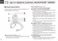
■ Front panel<br />
i o !0 !1 !2<br />
q<br />
w<br />
e<br />
r<br />
t<br />
y<br />
u<br />
!3 !4 !5<br />
q POWER SWITCH [POWER] (p. 3-2)<br />
Turn the internal power supply ON before turning the<br />
unit ON from the front panel. The internal power supply<br />
switch is located on the rear panel. (p. 3-2)<br />
➥ Push to turn the receiver power ON.<br />
• The [POWER] indicator above this switch lights green<br />
when powered ON.<br />
➥ Push for 1 sec. to turn the receiver power OFF.<br />
• The [POWER] indicator lights orange when the receiver<br />
is OFF when the internal power supply is<br />
switched ON.<br />
w REMOTE CONTROL SWITCH [LOCAL]<br />
Push to cancel remote control operation from a PC<br />
via a CI-V data.<br />
• The [REMOTE] indicator lights orange while in remote<br />
control operation.<br />
• When the [REMOTE] indicator lights orange, all dials,<br />
keys or switches other than this switch are disabled.<br />
e PANEL LOCK SWITCH [PANEL LOCK] (p. 9-2)<br />
➥ Push to turn the panel lock function ON or OFF.<br />
The panel lock function locks all dials (depends on<br />
set mode setting on p. 11-10), keys and switches<br />
other than [POWER] and [PANEL LOCK].<br />
• The [PANEL LOCK] indicator above this switch lights<br />
green when the panel lock is in use.<br />
• The dial lock function is also available.<br />
➥ Push and hold for 1 sec. to turn the panel lock<br />
with display sleep function ON.<br />
• Pushing [PANEL LOCK] turns this function OFF.<br />
• The [PANEL LOCK] indicator above this switch lights<br />
green and the display turns OFF when the sleep<br />
function is in use.<br />
r TIMER SWITCH [TIMER] (p. 10-3)<br />
➥ Turns the sleep or daily timer function ON or<br />
OFF.<br />
• The [TIMER] indicator above this switch lights green<br />
when the timer is in use.<br />
➥ Enters timer set mode when pushed and held for<br />
1 sec.<br />
t RECORDER REMOTE JACK [REC REMOTE]<br />
Controls the operation of a tape recorder for recording.<br />
Connects to the REMOTE jack on a tape<br />
recorder.<br />
y RECORDER JACK [REC OUT]<br />
Outputs an audio signal. Connect to the AUX or<br />
LINE IN jack on a tape recorder.<br />
u HEADPHONE JACK [PHONES]<br />
Accepts standard 3.5 (d) mm ( 1 ⁄8) stereo headphones.<br />
• Output power: 40 mW with an 8 Ω load.<br />
• When headphones are connected, the internal speaker<br />
or connected external speaker does not function.<br />
1-2
PANEL DESCRIPTION<br />
1<br />
i SQUELCH CONTROL [SQUELCH] (p. 3-8)<br />
Adjusts the squelch threshold level. The squelch<br />
disables output from the speaker (closed condition)<br />
when no signal is received.<br />
• The squelch control is particularly effective for FM or<br />
AM. It is also available for other modes.<br />
•11 to 12 o’clock position is recommended for any setting<br />
of the [SQL] control.<br />
Shallow<br />
Deep<br />
o PASSBAND TUNING CONTROLS [TWIN PBT]<br />
(p. 5-11)<br />
Adjusts the IF filter “passband width” via the DSP.<br />
• Passband width and shift frequency are shown on the<br />
multifunction display.<br />
• Push and hold [PBT CLEAR] for 1 sec. to clear the PBT<br />
settings.<br />
•Variable range is set to half of the IF filter passband<br />
width. 25 Hz steps and 50 Hz steps are available in<br />
SSB, CW and FSK modes.<br />
(PBT1)<br />
Squelch<br />
threshold<br />
Squelch<br />
is open.<br />
Noise squelch<br />
Shallow<br />
Deep<br />
(PBT2)<br />
S-meter<br />
squelch<br />
– +<br />
!1 AGC CONTROL [AGC] (p. 5-10)<br />
Adjusts the continuously-variable AGC circuit time<br />
constant.<br />
•To use [AGC] control, push the appropriate band’s<br />
[AGC VR/OFF] ([AGC VR] indicator lights green).<br />
!2 AGC SWITCH [AGC VR/OFF] (p. 5-10)<br />
➥ Push to toggle [AGC] control usage ON or OFF.<br />
• Use [AGC] control to set the AGC time constant when<br />
switched ON.<br />
• The [AGC VR] indicator above this switch lights<br />
green when the control is ON.<br />
➥ Turns the AGC function OFF when pushed and<br />
held for 1 sec.<br />
!3 AUTO NOTCH SWITCH [ANF] (p. 5-16)<br />
➥ Turns the auto notch function ON or OFF when<br />
pushed in SSB, AM, FM and WFM mode.<br />
•“ ” appears when auto notch is in use.<br />
AN<br />
Fast<br />
Slow<br />
!4 MANUAL NOTCH SWITCHES<br />
[NOTCH1]/[NOTCH2] (p. 5-16)<br />
➥ Turns the manual notch function ON or OFF<br />
when pushed in SSB, CW, AM and FSK mode.<br />
•“ MN1 ” or “ MN2 ” appear when manual notch is in<br />
use.<br />
➥ Switches the manual notch characteristics between<br />
wide, middle and narrow when pushed<br />
and held for 1 sec.<br />
✔ What is the notch function?<br />
The notch function eliminates unwanted CW or AM carrier<br />
tones while preserving the desired voice signal. The DSP circuit<br />
automatically adjusts the notch frequency to effectively<br />
eliminate unwanted tones.<br />
High cut<br />
Center<br />
Low cut<br />
✔ What is the PBT control?<br />
The PBT function electronically modifies the IF passband<br />
width to reject interference. This receiver uses the DSP circuit<br />
for the PBT function.<br />
!0 PBT CLEAR SWITCH [PBT CLEAR] (p. 5-11)<br />
Push and hold for 1 sec. to clear the PBT settings.<br />
• The [PBT CLEAR] indicator above this switch lights<br />
when PBT is in use.<br />
!5 MANUAL NOTCH FILTER CONTROLS<br />
[NOTCH1]/[NOTCH2] (p. 5-16)<br />
Varies the “notch” frequency of the manual notch filter<br />
to reject an interfering signal while the manual<br />
notch function is ON.<br />
• Notch filter center frequency:<br />
SSB : –1060 Hz to 4040 Hz<br />
CW : CW pitch freq. + 2540 Hz to CW pitch freq.<br />
–2540 Hz<br />
AM : –5100 Hz to 5100 Hz<br />
Lower<br />
frequency<br />
NOTCH1<br />
NOTCH2<br />
Higher<br />
frequency<br />
1-3
1 PANEL DESCRIPTION<br />
■ Front panel (continued)<br />
!6<br />
!7<br />
!8<br />
!9<br />
@0<br />
@1 @2 @3 @4 @5<br />
!6 NOISE REDUCTION SWITCH [NR] (p. 5-16)<br />
Push to switch the DSP noise reduction ON or OFF.<br />
• The [NR] indicator above this switch lights green when<br />
the function is activated.<br />
!7 NOISE BLANKER SWITCH [NB] (p. 5-15)<br />
➥ Selects from noise blanker 1, 2, or OFF when<br />
pushed. The noise blanker reduces pulse-type<br />
noise such as that generated by automobile ignition<br />
systems. This function cannot be used for<br />
FM, WFM, P25 modes or non-pulse-type noise.<br />
• The [NB] indicator above this switch lights green and<br />
“ NB1 ” or “ NB2 ” appears on the display when the<br />
function is activated.<br />
➥ Enters blank-width set mode when pushed and<br />
held for 1 sec.<br />
!8 AUDIO PEAK FILTER/TWIN PEAK FILTER<br />
SWITCH [APF/TPF]<br />
➥ Push to turn the audio peak filter ON or OFF during<br />
CW mode operation. (p. 4-9)<br />
➥ Push to turn the twin peak filter ON or OFF during<br />
FSK mode operation. (p. 4-11)<br />
•“ APF ” appears when audio peak filter is in use.<br />
•“ TPF ” appears when twin peak filter is in use.<br />
➥ During CW mode operation, push and hold for<br />
1 sec. to select the APF passband width from 80,<br />
160 and 320 Hz. (p. 4-9)<br />
!9 NOISE REDUCTION LEVEL CONTROL<br />
[NR LEVEL] (outer control; p. 5-16)<br />
Adjusts the DSP noise reduction level when noise<br />
reduction is in use. Set for maximum readability.<br />
•To use this control, noise reduction must be ON.<br />
Decreases<br />
@0 NOISE BLANKER CONTROL [NB LEVEL]<br />
(inner control; p. 5-15)<br />
Adjust the noise blanker threshold level.<br />
•To use this control, either noise blanker must be ON.<br />
Shallow<br />
Increases<br />
Deep<br />
@1 RF GAIN CONTROL [RF] (outer control; p. 3-8)<br />
Adjusts the RF gain level.<br />
While rotating the RF gain control, you may hear<br />
noise. This comes from the DSP unit and does<br />
not indicate a malfunction.<br />
Sensitivity<br />
increases<br />
Sensitivity<br />
decreases<br />
1-4
PANEL DESCRIPTION<br />
1<br />
@2 AF CONTROL [AF] (inner control; p. 3-8)<br />
Varies the audio output level of the speaker or<br />
headphones.<br />
Audio output<br />
decreases<br />
@3 BASS RESPONSE CONTROL [BASS]<br />
(outer control; p. 3-9)<br />
Adjusts the bass response of the audio output.<br />
Bass level<br />
decreases<br />
@4 TREBLE RESPONSE CONTROL [TREBLE]<br />
(inner control; p. 3-9)<br />
Adjusts the treble response of the audio output.<br />
Treble level<br />
decreases<br />
Audio output<br />
increases<br />
Bass level<br />
increases<br />
Treble level<br />
increases<br />
@5 MULTIFUNCTION SWITCHES<br />
Push to select the functions indicated in the LCD<br />
display to the right of these switches.<br />
• Functions vary depending on the operating condition.<br />
➥ While operating HF bands, selects the<br />
antenna connector from HF ANT 1, HF<br />
ANT 2 and HF ANT 3 when pushed.<br />
(p. 9-3)<br />
• During 30–1150 MHz operation, only ANT 1<br />
is available.<br />
• During 1150–3335 MHz operation, only ANT<br />
2 is available.<br />
➥ Turns the antenna control voltage ON<br />
and OFF form [ANT SEL] when pushed<br />
and held for 1 sec. (p. 9-3)<br />
➥ Selects one of 2 receive RF preamps or<br />
bypasses them. (p. 5-9)<br />
● HF bands<br />
•“P. AMP1” activates 10 dB preamp.<br />
•“P. AMP2” activates high-gain preamp.<br />
● Above 30 MHz bands<br />
• Only “P. AMP” is available.<br />
✔ What is the preamp?<br />
The preamp amplifies received signals in the front end circuit<br />
to improve S/N ratio and sensitivity. Select “P. AMP1” or<br />
“P. AMP2” when receiving weak signals.<br />
➥ Selects the attenuator when pushed.<br />
(p. 5-9)<br />
• HF bands: 6, 12, 18, 24, 30 dB.<br />
• 30–1150 MHz: 10, 20, 30 dB.<br />
•1150–3335 MHz: 20 dB only.<br />
➥ Turns OFF the attenuator when pushed<br />
and held for 1 sec. (p. 5-9)<br />
✔ What is the attenuator?<br />
The attenuator prevents a desired signal from distorting<br />
when very strong signals are near the receiving frequency,<br />
or when very strong electric fields, such as from a broadcasting<br />
station, are near your location.<br />
➥ Selects one of 3 IF filter settings.<br />
➥ Enters the filter set screen when pushed<br />
and held for 1 sec.<br />
➥ Activates and selects fast, middle or slow<br />
AGC time constant when pushed.<br />
(p. 5-10)<br />
• In FM, WFM or P25 mode, only “FAST” is<br />
available.<br />
• “VR (volume)” indicates that AGC time constant<br />
depends on [AGC] control.<br />
➥ Enters the AGC set mode when pushed<br />
and held for 1 sec. (p. 5-10)<br />
AGC time constant can be set from 0.1 to 8.0 sec.<br />
(depends on mode), or turned OFF. When AGC is<br />
“OFF,” the S-meter does not function.<br />
✔ What is the AGC?<br />
The AGC controls receiver gain to produce a constant audio<br />
output level, even when the received signal strength varies<br />
dramatically. Select “FAST” for tuning and then select “MID”<br />
or “SLOW” depending on the receiving conditions.<br />
➥ Switches between the tone squelch,<br />
DTCS squelch function and no-tone operation<br />
when pushed in FM mode.<br />
(p. 4-4)<br />
➥ Enters the tone set mode when pushed<br />
and held for 1 sec. in FM, FSK mode.<br />
(pgs. 4-4, 4-12)<br />
➥ Push to toggle the CW pitch setting<br />
screen ON and OFF in CW mode.<br />
(p.4-9)<br />
(Requires optional UT-122)<br />
➥ Switches the digital squelch between<br />
NAC squelch, selective squelch and<br />
OFF in P25 mode. (p. 4-19)<br />
➥ Enters the code set mode when pushed<br />
and held for 1 sec. in P25 mode.<br />
(p. 4-19)<br />
➥ Push to switch the voice squelch control<br />
function ON and OFF; useful for scanning.<br />
(p. 8-3)<br />
1-5
1 PANEL DESCRIPTION<br />
■ Front panel (continued)<br />
@6 @7 @8 @9 #0 #1 #2 #3 #4 #5 #6 #7 #8 #9 $0<br />
$1 $2 $3 $4<br />
@6 LCD FUNCTION DISPLAY (p. 1-10)<br />
Shows the operating frequency, function switch<br />
menus, spectrum scope screen, memory channel<br />
screen, set mode settings, etc.<br />
@7 RECEIVE IND<strong>IC</strong>ATOR [RECEIVE]<br />
Lights green while receiving a signal and when the<br />
squelch is open.<br />
@8 TUNING STEP SWITCHES [▲UP]/[▼DOWM]<br />
(p. 3-5)<br />
➥ Select the tuning step for the main dial. Push<br />
[▲UP] to select a larger tuning step; push<br />
[▼DOWN] to select a smaller tuning step.<br />
•1 Hz, 10 Hz, 100 Hz, 1 kHz, 2.5 kHz, 5 kHz, 6.25<br />
kHz, 9 kHz, 10 kHz, 12.5 kHz, 20 kHz, 25 kHz, 100<br />
kHz and 1 MHz are selectable.<br />
• Programmable tuning steps can be set between 0.1<br />
and 999.9 kHz in 0.1 kHz steps.<br />
➠ To set programmable tuning steps, enter the desired<br />
steps via the keypad, then push [YUP] or<br />
[ZDOWN].<br />
➥ Push and hold [▲UP] (or [▼DOWN]) for 1 sec.<br />
to enter the tuning step select screen.<br />
• Unwanted tuning step for each operating mode can<br />
be skipped in the tuning step select.<br />
@9 MEMORY TRANSFER SWITCH [M≈V] (p. 7-5)<br />
Transfers the memory contents to VFO when<br />
pushed and held for 1 sec.<br />
• This function is available both in VFO and memory<br />
modes.<br />
#0 MEMORY SWITCH [MEMO] (p.7-3)<br />
➥ Selects the memory mode when pushed.<br />
• After pushing one to three digit (0 to 999), pushing<br />
the switch selects a memory channel.<br />
➥ Memory bank limit function ON or OFF when<br />
pushed and held for 1 sec.<br />
#1 REMOTE CONTROL IND<strong>IC</strong>ATOR [REMOTE]<br />
Lights yellow when a command is received from a<br />
PC via CI-V data.<br />
• When this indicator lights yellow, all dials, keys or<br />
switches other than [LOCAL] are disabled.<br />
• This indicator goes OFF, when [LOCAL] is pushed.<br />
#2 DIAL LOCK IND<strong>IC</strong>ATOR [LOCK] (p. 9-2)<br />
Lights orange when the dial lock function is activated.<br />
1-6
1⁄ 4 •“ ” appears when 1⁄4 function is in use.<br />
PANEL DESCRIPTION 1<br />
#3 VFO SWITCH [VFO]<br />
$1 LCD FUNCTION SWITCHES [F-1]–[F-7]<br />
Selects the VFO mode when pushed. (p. 3-3)<br />
• After pushing a digit switch (0 to 9), push this switch selects<br />
a VFO mode (VFO-0 to VFO-9).<br />
#4 KEYPAD (pgs. 3-3, 3-4, 7-3)<br />
Enters a frequency or memory channel. Pushing<br />
[ENT], [VFO] or [MEMO] ends keypad input.<br />
• e.g. to enter 14.195 MHz, push [1] [4] [•] [1] [9] [5]<br />
[ENT].<br />
Push to select the function indicated in the LCD display<br />
above these switches.<br />
• Functions vary depending on the operating condition.<br />
$2 MINI SPECTRUM SCOPE SWITCH [M.SCOPE]<br />
(p. 5-6)<br />
➥ Turns the mini spectrum scope screen ON or<br />
OFF.<br />
• The mini spectrum scope screen can be displayed<br />
with another screen, such as memory or set mode<br />
#5 ENTER SWITCH [ENT]<br />
screen, simultaneously.<br />
Enters input frequency. (pgs. 3-4)<br />
➥ Turns the spectrum scope screen ON when<br />
#6 MEMORY WRITE SWITCH [MW] (p. 7-4)<br />
pushed and held for 1 sec.<br />
Stores the selected readout frequency and operating<br />
mode into the displayed memory channel when Selects the desired mode. (p. 3-7)<br />
$3 MODE SWITCHES<br />
pushed and held for 1 sec.<br />
• Announces selected mode via the speech synthesizer.<br />
• This function is available both in VFO and memory (p. 11-11)<br />
modes.<br />
➥ Selects FM mode.<br />
#7 MEMORY CLEAR SWITCH [M-CL] (p. 7-7)<br />
Push and hold to clear the contents of displayed<br />
WFM<br />
memory channel.<br />
#8 SPEAKER<br />
Outputs audio signals.<br />
➥ Selects WFM mode.<br />
➥ Selects AM and S-AM modes alternately.<br />
➥ Switches S-AM(D), S-AM(U) and S-<br />
AM(L) mode when pushed and held for<br />
#9 1/4-SPEED TUNING SWITCH [1/4]<br />
➥ Push to turn the 1⁄4-speed tuning function ON or<br />
1 sec. in S-AM mode.<br />
OFF in CW and FSK modes. (p. 3-6)<br />
SSB/CW<br />
• 1⁄4 function sets dial rotation to 1⁄4 of normal speed<br />
for fine tuning.<br />
➥ Push and hold to turn the dial click function ON<br />
or OFF. (p. 9-3)<br />
$0 AFC/AUTOMAT<strong>IC</strong> TUNING SWITCH<br />
[AFC•AUTOTUNE]<br />
➥ Turns the AFC function ON or OFF in FM or<br />
WFM modes.<br />
•“ AFC ” appears when AFC function is in use.<br />
➥ Turns the automatic tuning function ON or OFF<br />
in AM, SSB and CW modes.<br />
•“ AUTO TUNE ” blinks when autotune function is activate.<br />
IMPORTANT!<br />
When receiving a weak signal, or receiving a<br />
signal with interference, the automatic tuning<br />
function may tune the receiver to an undesired<br />
signal.<br />
FSK<br />
DIGITAL<br />
➥ Switches between SSB and CW mode.<br />
➥ Switches between LSB and USB mode<br />
when pushed and held for 1 sec. in SSB<br />
mode.<br />
➥ Switches between CW and CW-R (CW<br />
reverse) mode when pushed and held for<br />
1 sec. in CW mode.<br />
➥ Selects FSK and FSK-R (FSK reverse)<br />
modes alternately.<br />
➥ Selects Digital (P25) mode. (Requires<br />
optional UT-122.)<br />
$4 DISPLAY SWITCH [DISPLAY]<br />
➥ Push to toggle the external input screen between<br />
mini video screen, full video screen, or OFF.<br />
• If no signal inputs from [VIDEO IN], black screen appears.<br />
➥ Enter the display set mode menu screen when<br />
pushed and held for 1 sec.<br />
1-7
1 PANEL DESCRIPTION<br />
■ Front panel (continued)<br />
^0<br />
%9<br />
$5 $6 $7 $8 $9 %0 %1<br />
%2 %3 %4 %5 %6 %7 %8<br />
$5 DIMMER SWITCH [DIMMER] (p.11-26)<br />
➥ Push to turn the dimmer function ON or OFF.<br />
• When this function is ON, LEDs and LCD backlight<br />
become dim according to the preset setting.<br />
➥ Push and hold for 1 sec. to reset the LCD setting<br />
to the default value with the dimmer function ON<br />
and OFF.<br />
$6 LCD SET SWITCH [LCD SET] (p. 11-26)<br />
➥ Push to toggle the LCD setting screen ON or<br />
OFF.<br />
• LCD contrast and backlight’s brightness can be set.<br />
$7 DUPLEX SWITCH [DUP] (p. 4-3)<br />
➥ Push to select the duplex function (DUP–, DUP+<br />
and OFF).<br />
➥ Push and hold for 1 sec. to enter the offset frequency<br />
set mode.<br />
$8 VO<strong>IC</strong>E MEMORY RECORD SWITCH [REC]<br />
➥ Short recording; Push momentarily to record the<br />
signal received for the preset time period before<br />
[REC] was pushed. (p.6-5)<br />
• Starts recording again automatically.<br />
➥ Regular recording; Push and hold for 1 sec. to<br />
record the received signal until recording is<br />
stopped. (p. 6-3)<br />
• Push and hold this switch for 1 sec. to stop recording.<br />
$9 SHORT VO<strong>IC</strong>E MEMORY PLAY BACK SWITCH<br />
[PLAY] (p. 6-5)<br />
➥ Plays back the audio previously recorded during<br />
the preset time period when pushed.<br />
➥ Plays back all of the previously recorded audio<br />
when pushed and held for 1 sec.<br />
%0 EXIT/SET SWITCH [EXIT/SET]<br />
➥ Push to exit, or return to the previous screen during<br />
spectrum scope, memory, scan or set mode<br />
screen display.<br />
➥ Displays set mode menu screen when pushed<br />
and held for 1 sec.<br />
1-8
PANEL DESCRIPTION<br />
1<br />
%1 MONITOR SWITCH [MONI] (pgs. 3-8, 4-4, 4-19)<br />
➥ Push and hold to open the squelch manually.<br />
• The [MONI] indicator appears on the display.<br />
• While pushing and holding this switch, release any<br />
other receiving functions such as the noise blanker<br />
or ANF.<br />
• While in a duplex operation, monitor the shifted frequency.<br />
%2 MAIN DIAL<br />
Changes the displayed frequency, selects set mode<br />
setting, etc.<br />
%3 LOCK SWITCH [LOCK] (p. 9-2)<br />
Push to turn the dial lock function ON or OFF.<br />
%4 SPEECH SWITCH [SPCH] (p. 9-2)<br />
➥ Push to announce the S-meter indication and the<br />
selected readout frequency.<br />
➥ The selected operating mode is also announced<br />
when pushed and held for 1 sec.<br />
%5 MEMORY DIAL [M-CH] (inner control; p. 7-3)<br />
Rotate to select the desired memory channel.<br />
• Memory channels can be selected both in VFO and<br />
memory modes.<br />
%6 MEMORY BANK DIAL [BANK]<br />
(outer control; p. 7-3)<br />
Rotate to select the desired memory bank.<br />
• Memory banks can be selected both in VFO and memory<br />
modes.<br />
%7 SCAN SPEED CONTROL [SPEED]<br />
(inner control; p. 8-18)<br />
Rotate to adjust the scan speed.<br />
%8 SCAN DELAY CONTROL [DELAY]<br />
(outer control; p. 8-18)<br />
Rotate to adjust the desired scan delay time.<br />
• This setting is effective when “DELAY” is selected for the<br />
scan resume condition (%6).<br />
• Scan delay time is adjustable between 2 sec. to 20 sec.<br />
%9 SCAN RESUME SWITCHES [OFF]/[DELAY]/[∞]<br />
(p. 8-17)<br />
Push to select a scan resume condition.<br />
• The [SCAN RESUME] indicator lights green above the<br />
selected switch.<br />
^0 SCAN START SWITCHES<br />
(pgs. 8-5, 8-7 to 8-11, 8-13, 8-14)<br />
Push to start the desired scan.<br />
1-9
1 PANEL DESCRIPTION<br />
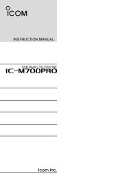
■ Rear panel<br />
qw e r t yuio!0 !1 !2 !3 !4 !5 !6 !7<br />
@9 @8 @7 @6 @5 @4 @3 @2 @1 @0 !9 !8<br />
q EXTERNAL SPEAKER JACK [EXT-SP] (p. 2-6)<br />
Connects an external speaker (4–8 Ω), if desired.<br />
w DC OUTPUT JACK [DC OUTPUT] (p. 2-6)<br />
Outputs regulated 15 V DC (approx.) for external<br />
equipment. Connected in parallel with 13.8 V outputs<br />
of [ACC]. (max. 1 A total)<br />
_<br />
e ACCESSORY SOCKET [ACC] (p. 2-6)<br />
Enables connection of external equipment such as<br />
an automatic antenna selector, a TNC for data communications,<br />
etc.<br />
• See p. 2-12 for socket information.<br />
r ANTENNA SELECTOR VOLTAGE OUTPUT<br />
JACK [ANT SEL]<br />
Outputs regulated 13.8 V DC (max. 100 mA) for external<br />
preamplifier or antenna selector, etc.<br />
t REFERENCE SIGNAL INPUT/OUTPUT<br />
TERMINAL [REF I/O 10MHz–10dBm]<br />
Inputs/outputs a 10 MHz reference signal.<br />
y SPEECH OUTPUT JACK [SPEECH OUT] (p. 2-9)<br />
Outputs an operating frequency, mode, S-meter indication<br />
and time with a synthesized voice when<br />
pushing [SPCH] or scan stopped.<br />
•Turn ON the “REC SPCH” in the others set mode to activate<br />
this jack when scan stopped. (p. 11-11)<br />
• Output level can be adjusted in ACC set mode. (p. 11-7)<br />
+<br />
_<br />
u LINE OUTPUT JACK [LINE OUT]<br />
Audio output jack for tape recorder. The fixed audio<br />
output level is set for a tape recorder AUX jack.<br />
i RECORDER REMOTE JACK [REC REMOTE]<br />
Controls the operation of a tape recorder for recording.<br />
Connects to the REMOTE jack on a tape<br />
recorder.<br />
o DETECTOR OUTPUT JACK [DET OUT]<br />
Outputs the detector output signal.<br />
!0 VIDEO INPUT JACK [VIDEO IN]<br />
Accepts video signals for display on the LCD monitor<br />
when the [DISPLAY] switch is ON.<br />
!1 VIDEO OUTPUT JACK [VIDEO OUT]<br />
Outputs video signals when TV frequencies with<br />
WFM mode are received. The NTSC M, PAL B/G,<br />
PAL I, PAL D and SECAM K system can be accepted.<br />
(No signals come out for USA version.)<br />
!2 SPARE JACK [SPARE] (p. 2-3)<br />
No connection.<br />
!3 IF OUTPUT JACK [IF OUT] (p. 2-3)<br />
Outputs a 10.7 MHz IF signal.<br />
Output level is the same level as an antenna input<br />
signal or below (when the AGC function is activated<br />
or attenuator is ON.)<br />
!4 DC-DC POWER SOCKET [DC-DC IN] (p. 2-6)<br />
Accepts a regulated 13.5 to 15 V DC input. This<br />
socket does not accept voltage from a non-regulated<br />
power source such as a vehicle’s battery.<br />
1-10
PANEL DESCRIPTION<br />
1<br />
!5 FUSE HOLDER [FUSE] (p. 12-8)<br />
Holds a 4 A fuse (100 V/120 V versions) or 2 A fuse<br />
(230 V/240 V versions) for internal AC power supply<br />
protection. Cuts off the AC input when over-current<br />
occurs.<br />
CAUTION: Always use the correct fuse for AC<br />
input power. Using a fuse rated for a different<br />
input power may damege your house electrical<br />
system or the receiver.<br />
!6 AC POWER SOCKET [AC] (p. 2-5)<br />
Connects the supplied AC power cable to an AC<br />
line-voltage receptacle.<br />
!7 MAIN POWER SWITCH [I/O] (p. 3-2)<br />
Turns the internal power supply ON or OFF.<br />
!8 GROUND TERMINAL [GND] (p. 2-2)<br />
Connect this terminal to a ground to prevent electrical<br />
shocks, TVI, BCI and other problems.<br />
!9 HF ANTENNA CONNECTOR 1 [HF ANT 1]<br />
(p. 2-5)<br />
Accepts a 50 Ω antenna for HF bands with a PL-<br />
259 plug connector.<br />
@6 EXTERNAL DISPLAY TERMINAL<br />
[EXT-DISPLAY] (p. 2-10)<br />
Connects to an external display monitor.<br />
• At least 800×600 pixel display is necessary.<br />
@7 RS-232C TERMINAL [RS-232C] (p. 2-6)<br />
Connects to a PC using a D-sub 9-pin RS-232C<br />
cable.<br />
Can be used for remote control of the <strong>IC</strong>-<strong>R9500</strong><br />
without the optional CT-17, or the FSK decoded signal<br />
output. The [RS-232C] interface is wired as a<br />
modem (DCE).<br />
@8 CI-V REMOTE CONTROL JACK [REMOTE]<br />
(p. 2-6)<br />
➥ Connects a PC via the optional CT-17 CI-V LEVEL<br />
CONVERTER for external control of the receiver.<br />
➥ Used for transceive operation with another Icom<br />
CI-V transceiver or receiver.<br />
@9 DATA SOCKET [DATA IN]<br />
(pgs. 2-10, 2-12)<br />
Outputs LCD monitor signals (NTSC system).<br />
@0 HF ANTENNA CONNECTOR 2 [HF ANT 2]<br />
(p. 2-5)<br />
Accepts a 500 Ω antenna for HF band with an RCA<br />
connector.<br />
@1 USB CONNECTOR [USB]<br />
Connects USB equipment such as a memory<br />
media, hub or keyboard.<br />
@2 S/P DIF OUTPUT TERMINAL [S/P DIF OUT]<br />
(p. 2-7)<br />
Connects external equipment that supports S/P DIF<br />
output.<br />
@3 HF ANTENNA CONNECTOR 3/ANTENNA CON-<br />
NECTOR 1 [ANT 1/HF ANT 3] (p. 2-5)<br />
Accepts a 50 Ω antenna with a Type-N connector.<br />
Covers the HF bands and 30–1150 MHz frequency<br />
range.<br />
@4 ETHERNET CONNECTOR [LAN] (pgs. 2-7, 15-6)<br />
Connects to a PC through a LAN (Local Area Network).<br />
@5 ANTENNA CONNECTOR 2 [ANT 2] (p. 2-5)<br />
Accepts a 50 Ω antenna with a Type-N connector.<br />
Covers the 1150–3335 MHz frequency range.<br />
1-11
1 PANEL DESCRIPTION<br />
■ LCD display<br />
@9 @8 @7 @6 @5 @4 @3 @2<br />
q<br />
w<br />
e<br />
r<br />
t<br />
y<br />
u<br />
i<br />
o<br />
@1<br />
@0<br />
!9<br />
!8<br />
!7<br />
!6<br />
!5<br />
!4<br />
!3<br />
!2<br />
!1<br />
!0<br />
q RSSI (Received Signal Strength Indication) METER<br />
(p. 3-10)<br />
Shows the received signal strength. Four meter<br />
types, S, dBµ, dBµ(EMF) and dBm meters are selectable.<br />
• S-meter<br />
w CENTER METER<br />
Shows that the received signal is tuned to its center<br />
frequency for FM, WFM or FSK modes.<br />
• FM/WFM modes<br />
• FSK mode<br />
e MODE IND<strong>IC</strong>ATOR (p. 3-7)<br />
Shows the selected receive mode.<br />
• dBµ meter<br />
• dBµ (EMF) meter<br />
• dBm meter<br />
r VFO/MEMORY IND<strong>IC</strong>ATOR (pgs. 3-3, 7-3)<br />
Indicates the selected VFO number (VFO-0 to VFO-<br />
9) or memory mode.<br />
t IF FILTER IND<strong>IC</strong>ATOR (p. 5-12)<br />
Shows the selected IF filter number.<br />
y FREQUENCY READOUTS<br />
Shows the operating frequency.<br />
u SELECT MEMORY CHANNEL IND<strong>IC</strong>ATOR (p. 8-12)<br />
Indicates the displayed memory channel is set as a<br />
select memory channel.<br />
i MEMORY CHANNEL READOUTS<br />
➥ Shows the selected memory channel contents in<br />
VFO mode.<br />
➥ Shows the VFO contents in memory mode.<br />
1-12
PANEL DESCRIPTION<br />
1<br />
o MULTIFUNCTION SWITCH GUIDE<br />
Indicates the function of the multifunction switches.<br />
!0 LCD FUNCTION SWITCH GUIDE<br />
Indicates the function of the LCD function switches<br />
([F-1] – [F-7]).<br />
!1 MULTIFUNCTION SCREEN<br />
Shows the screens for the spectrum scope, voice<br />
recorder, memory channel list, scan, FSK decoder,<br />
IF filter selection or set modes, etc.<br />
!2 TUNING STEP IND<strong>IC</strong>ATOR (p. 3-5)<br />
Shows the selected tuning step.<br />
!3 1/4 FUNCTION IND<strong>IC</strong>ATOR (p. 3-6)<br />
Appears when the 1/4-speed tuning function is activated<br />
in CW and FSK modes.<br />
!4 AUTOMAT<strong>IC</strong> TUNE IND<strong>IC</strong>ATOR (p. 5-17)<br />
“ AUTO TUNE ” blinks during automatic tuning. This<br />
feature is active in AM, SSB and CW mode.<br />
!5 MEMORY CHANNEL IND<strong>IC</strong>ATOR (p. 7-3)<br />
Indicates the selected memory channel number.<br />
!6 TUNING DIGIT IND<strong>IC</strong>ATOR (p. 3-5)<br />
Shows the tuneable digit when rotating the main<br />
dial.<br />
!7 TONE/DTCS/NAC/SELECTIVE SQUELCH<br />
IND<strong>IC</strong>ATOR<br />
➥ “ TSQL ” or “ DTCS ” appears when the tone<br />
squelch or DTCS squelch is set in FM mode.<br />
(p. 4-4)<br />
➥ “ NAC ” or “ SEL ” appears when the NAC<br />
squelch or selective squelch is selected in P25<br />
mode. (Requires optional UT-122.) (p.4-19)<br />
@1 CLOCK READOUT (p. 10-2)<br />
Shows the current time. Local and UTC time can indicate<br />
at the same time.<br />
@2 NOISE REDUCTION IND<strong>IC</strong>ATOR (p. 5-16)<br />
Appears when noise reduction function is in use.<br />
@3 BANDPASS FILTER IND<strong>IC</strong>ATOR<br />
Appears when the narrow filter (500 Hz or less) is<br />
selected during CW or FSK operation.<br />
@4 PASSBAND WIDTH IND<strong>IC</strong>ATOR (p. 5-11)<br />
Graphically displays the passband width for twin<br />
PBT operation and center frequency for IF shift operation.<br />
@5 AUDIO PEAK FILTER IND<strong>IC</strong>ATOR (p. 4-9)<br />
Appears when the audio peak filter function is in use.<br />
This function is available in CW mode<br />
@6 SHIFT FREQUENCY IND<strong>IC</strong>ATOR (p. 5-11)<br />
Shows the shift frequency of the IF filter.<br />
@7 NOTCH FILTER IND<strong>IC</strong>ATOR (p. 5-16)<br />
➥ “ AN ” appears when the auto notch function is in<br />
use. This function is available in FM, WFM, AM<br />
and SSB modes.<br />
➥ “ MN1 ” or “ MN2 ” appears when the manual notch<br />
filter function is in use. This function is available in<br />
AM, SSB, CW and FSK mode.<br />
@8 BAND WIDTH IND<strong>IC</strong>ATOR (p. 5-11)<br />
Shows the passband width of the IF filter.<br />
@9 DUPLEX IND<strong>IC</strong>ATOR (p. 4-3)<br />
“ DUP– ” or “ DUP+ ” appears when the negative duplex<br />
or positive duplex operation is selected, respectively.<br />
!8 BANK IND<strong>IC</strong>ATOR (p. 7-3)<br />
Appears when the bank limit function is in use and<br />
indicates the selected bank number.<br />
• BANK-0 to BANK-9, BANK-A (AUTO MW), BANK-S<br />
(SKIP) and BANK-P (SCAN EDGE) are selectable.<br />
!9 NOISE BLANKER IND<strong>IC</strong>ATOR (p. 5-15)<br />
“ NB1 ” or “ NB2 ” appears when either noise<br />
blanker 1 or noise blanker 2 is ON. This function is<br />
not available for FM, WFM or P25 mode.<br />
@0 CF CARD/USB-MEMORY IND<strong>IC</strong>ATOR (p. 11-16)<br />
➥ “ CF ” appears when CF card is correctly connected<br />
and blinks while CF card is active.<br />
• This indicator is normally stayed ON.<br />
➥ “ USB ” appears when USB equipment (USB-<br />
Memory or keyboard, etc) is connected, and<br />
blinks while it is active.<br />
1-13
1 PANEL DESCRIPTION<br />
■ Screen menu arrangement<br />
The following screens can be selected from the start<br />
up screen. Choose the desired screen using the following<br />
chart.<br />
Pushing [EXIT/SET] several times returns to the start<br />
up screen. See p. 11-3 for set mode arrangement.<br />
• Spectrum scope screen (p. 5-2)<br />
• Memory channel screen (p. 7-4)<br />
• Voice recorder screen (p. 6-3)<br />
• Scan screen (p. 5-5)<br />
• FSK decoder screen (p. 4-14)<br />
• Set mode menu screen (p. 11-2)<br />
1-14
INSTALLATION AND CONNECTIONS Section 2<br />
■ Unpacking ……………………………………………………………… 2-2<br />
■ Selecting a location …………………………………………………… 2-2<br />
■ Grounding ……………………………………………………………… 2-2<br />
■ Antenna connection …………………………………………………… 2-3<br />
■ TV jumper cable connection …………………………………………… 2-4<br />
■ Carrying handle attachment …………………………………………… 2-4<br />
■ Rack mounting handle detachment …………………………………… 2-4<br />
■ Required connections ………………………………………………… 2-5<br />
D Rear panel …………………………………………………………… 2-5<br />
■ Advanced connections ………………………………………………… 2-6<br />
D Front panel …………………………………………………………… 2-6<br />
D Rear panel—1 ……………………………………………………… 2-6<br />
D Rear panel—2 ……………………………………………………… 2-7<br />
■ Tape recorder connections …………………………………………… 2-8<br />
D Recording from the front panel or rear panel …………………… 2-8<br />
D Separately recording audio and frequency ……………………… 2-9<br />
■ Monitor display connection …………………………………………… 2-10<br />
■ Transceive function …………………………………………………… 2-10<br />
■ FSK and AFSK (SSTV) connections ………………………………… 2-11<br />
■ Accessory connector information …………………………………… 2-12<br />
CAUTION!: The receiver weighs approx. 20 kg (44 lb). Always<br />
have two people available to carry, lift or<br />
turn over the receiver.<br />
2-1
2 INSTALLATION AND CONNECTIONS<br />
■ Unpacking<br />
After unpacking, immediately report any damage to the<br />
delivering carrier or dealer. Keep the shipping cartons.<br />
For a description and a diagram of accessory equipment<br />
included with the <strong>IC</strong>-<strong>R9500</strong>, see ‘Supplied accessories’<br />
on p. iii of this manual.<br />
■ Selecting a location<br />
Select a location for the receiver that allows adequate<br />
air circulation and access to the front and rear panels.<br />
Do not place in areas subject to extreme heat, cold, or<br />
vibrations, or near TV sets, radios and other electromagnetic<br />
sources.<br />
■ Grounding<br />
To prevent electrical shock, television interference<br />
(TVI), broadcast interference (BCI) and other problems,<br />
ground the receiver through the GROUND terminal<br />
on the rear panel.<br />
For best results, connect a heavy gauge wire or strap<br />
to a long earth-sunk copper rod. Make the distance between<br />
the [GND] terminal and ground as short as possible.<br />
R WARNING: NEVER connect the [GND]<br />
terminal to a gas or electric pipe, since the connection<br />
could cause an explosion or electric shock.<br />
2-2
INSTALLATION AND CONNECTIONS<br />
2<br />
■ Antenna connection<br />
Your antenna plays a very important role in receiver<br />
operation. If the antenna is poor, your receiver cannot<br />
give you the best performance.<br />
The <strong>IC</strong>-<strong>R9500</strong> requires at least 2 antennas (ANT 1/HF<br />
ANT 3, ANT 2) for full coverage from 100 kHz to 3335<br />
MHz. Select an antenna, such as a well matched 50 Ω<br />
antenna and feedline. When you wish to use a long<br />
wire antenna for short wave bands, use one as long as<br />
possible (at least 10 m, 32.8 ft).<br />
CAUTION: Protect your receiver from lightning by<br />
using a lightning arrestor.<br />
PL-259 CONNECTOR INSTALLATION EXAMPLE<br />
q<br />
Coupling ring<br />
30 mm<br />
10 mm (soft solder)<br />
Slide the coupling ring<br />
down. Strip the cable<br />
jacket and tin the<br />
braid.<br />
e<br />
solder solder<br />
Slide the connector<br />
body on and solder it.<br />
w<br />
10 mm<br />
Soft<br />
solder<br />
Strip the cable as<br />
shown at left. Tin the<br />
centerr conductor.<br />
r<br />
Screw the coupling<br />
ring onto the connector<br />
body.<br />
1–2 mm<br />
30 mm ≈ 9⁄8 in 10 mm ≈ 3⁄8 in 1–2 mm ≈ 1⁄16 in<br />
TYPE-N CONNECTOR INSTALLATION EXAMPLE<br />
q<br />
Nut<br />
Rubber gasket<br />
Washer<br />
Clamp<br />
15 mm<br />
Slide the nut, washer,<br />
rubber gasket and<br />
clamp over the<br />
coaxial cable, then<br />
cut the end of the<br />
cable evenly.<br />
e<br />
Solder hole<br />
No space<br />
Tin the center conductor.<br />
Install the center conductor<br />
pin and solder it.<br />
w<br />
3 mm 6 mm<br />
Center conductor<br />
Strip the cable and<br />
fold the braid back<br />
over the clamp.<br />
r<br />
Plug body<br />
Carefully slide the plug<br />
body into place aligning<br />
the center conductor pin<br />
on the cable. Tighten the<br />
nut onto the plug body.<br />
• Be sure the center pin is<br />
flush with the end of the<br />
plug body.<br />
15 mm ≈ 19⁄32 in 6 mm ≈ 1⁄4 in 3 mm ≈ 1⁄8 in<br />
2-3
2 INSTALLATION AND CONNECTIONS<br />
■ TV jumper cable connection (except for USA version)<br />
Connect the RCA cable between [VIDEO IN] and<br />
[VIDEO OUT].<br />
When connecting external video equipment, connect<br />
the unit between [VIDEO IN] and [VIDEO OUT] connectors.<br />
■ Carrying handle attachment<br />
q Remove the 2 screws from side panel for both side.<br />
w Attach the supplied Carrying handles as shown at<br />
left.<br />
FH M4×16 mm<br />
FH: Flat head<br />
■ Rack mounting handle detachment<br />
When removing the rack mounting handles, use the<br />
supplied screws for attach the side plates.<br />
q<br />
FH: Flat head<br />
PH: Pan head<br />
q Remove the 6 screws from the rack mounting handles<br />
for both side. And remove the rack mounting<br />
handles and side plates.<br />
w Attach the removed side plates to original position,<br />
then tighten the supplied 4 screws (FH M4×12).<br />
Tighten the supplied 2 screw (PH M4×8) for hiding<br />
screw holes for both side.<br />
FH M4×16 mm<br />
w<br />
FH M4×12 mm<br />
CAUTION: NEVER replace the any other than<br />
specified screws for side plate atachment or hiding<br />
screw holes. If long screw is used, it is<br />
caused to damage the receiver’s inside board.<br />
PH M4×8 mm<br />
2-4
INSTALLATION AND CONNECTIONS<br />
2<br />
■ Required connections<br />
D Rear panel<br />
[VIDEO IN], [VIDEO OUT]<br />
TV jumper cable must be connected<br />
when internal TV tuner and<br />
LCD are in use (except USA version).<br />
No signals come out from [VIDEO<br />
OUT] for USA version.<br />
Ground (p. 2-2)<br />
Ground connection<br />
AC outlet<br />
R WARNING:<br />
Use the supplied<br />
AC power cable<br />
only.<br />
Antenna 1, 2 (p. 2-3)<br />
Connects the VHF,<br />
UHF wide band antennas.<br />
HF Antenna 1, 2, 3 (p. 2-3)<br />
[Example]: HF ANT1 for 3.5, 7 MHz bands, HF ANT 2 for 14, 18<br />
MHz bands, ANT3 for 24, 28 MHz band.<br />
ANT1: 30–1150 MHz,<br />
ANT2: 1150–3335 MHz<br />
Select the active antenna connector. (p.9-3)<br />
2-5
2 INSTALLATION AND CONNECTIONS<br />
■ Advanced connections<br />
D Front panel<br />
[REC REMOTE],<br />
[REC OUT] (p. 2-8)<br />
Connects a tape recorder<br />
or other audio<br />
equipment.<br />
Headphones<br />
Accepts headphones<br />
with 8–16 Ω impedance.<br />
D Rear panel—1<br />
External speaker (p. 14-4)<br />
SP-20<br />
(option)<br />
[DC OUTPUT]<br />
Outputs regulated 15 V (approx.)<br />
DC for external equipment power<br />
supply. (max. 1 A capacity)<br />
ACC socket<br />
(pgs.2-12)<br />
[DC-DC IN]<br />
Connects an external power<br />
supply (DC 13.5–15 V at<br />
least 10 A).<br />
Only regulated DC power<br />
may be connected.<br />
DATA socket<br />
(pgs.2-12)<br />
Antenna 1, 2<br />
Connects a pre-amplifier,<br />
converter, etc.<br />
[REMOTE], [RS-232C] (p. 13-2)<br />
Used for computer control and transceive<br />
operation.<br />
The optional CT-17 is required when connecting<br />
a PC to [REMOTE].<br />
2-6
INSTALLATION AND CONNECTIONS<br />
2<br />
D Rear panel—2<br />
[METER]<br />
Connects an external<br />
meter, etc.<br />
Meter<br />
ANT SEL<br />
Video equipment<br />
Connects a video recorder,<br />
etc.<br />
GND<br />
7<br />
3 8<br />
5<br />
2<br />
MOUT<br />
6<br />
1<br />
4<br />
[ACC]<br />
When the [ANT] switch is ON:<br />
13.8 V DC output 100 mA max.<br />
* No signals come out from<br />
[VIDEO OUT] for USA version.<br />
External Display<br />
Connects a PC-style<br />
monitor display (at least<br />
800×600 resolution).<br />
Video output signal can<br />
be turned ON and OFF<br />
in set mode (p. 11-9)<br />
[S/P DIF IN/OUT]<br />
Connects a PC<br />
for audio signal<br />
data (48 kHz, 16-<br />
bit) output.<br />
[USB]<br />
Connects a USB<br />
equipment such as<br />
memory, hub or<br />
keyboard.<br />
Ethernet connector (p. 15-6)<br />
Connects a PC<br />
via a LAN for CPU<br />
firmware update.<br />
For Ferrite bead installation (example: LAN cable)<br />
LAN<br />
socket<br />
2-7
2 INSTALLATION AND CONNECTIONS<br />
■ Tape recorder connections<br />
The [REC REMOTE] jack is grounded when a signal<br />
is received and squelch opens. If a tape recorder has<br />
a control terminal, this jack can be used for recording<br />
control. (2 A/DC max.)<br />
The [REC OUT] or [LINE OUT] jack has 350 mV<br />
rms/4.7 kΩ output for connection to other audio equipment.<br />
D Recording from the front panel or rear panel<br />
The [REC REMOTE] jack is grounded when a signal<br />
is received and squelch opens. If a tape recorder<br />
has a control terminal, this jack can be used for<br />
recording control. (2 A/DC max.)<br />
The [REC OUT] or [LINE OUT] jack has 350 mV<br />
rms/4.7 kΩ output for connection to other audio<br />
equipment.<br />
• Recording from the front panel<br />
When you wish to control a tape<br />
recorder via the REMOTE jack.<br />
[REMOTE] jack<br />
[AUX IN] or<br />
[LINE IN] jack<br />
[REC<br />
REMOTE]<br />
[REC OUT]<br />
350 mVrms<br />
4.7 kΩ<br />
FRONT<br />
• Recording from the rear panel<br />
[REMOTE] jack<br />
[REC REMOTE]<br />
[LINE OUT]<br />
350 mVrms<br />
4.7 kΩ<br />
When you wish to control a tape<br />
recorder via the REMOTE jack.<br />
REAR<br />
[AUX IN] or [LINE IN] jack<br />
2-8
INSTALLATION AND CONNECTIONS<br />
2<br />
D Separately recording audio and frequency<br />
When using a stereo tape recorder for recording,<br />
received audio and a frequency with a synthesized<br />
voice can be separately recorded.<br />
When recording this way, you can search ahead of<br />
the audio signal recorded in the tape recorder using<br />
the frequency recording channel search.<br />
[REMOTE] jack<br />
[REC REMOTE]<br />
[LINE OUT]<br />
350 mVrms<br />
4.7 kΩ<br />
[SPEECH OUT]<br />
350 mVrms<br />
4.7 kΩ<br />
When you wish to control a tape<br />
recorder via the REMOTE jack.<br />
REAR<br />
[AUX IN] jacks L and R<br />
• Be sure the “REC SPEECH” item is turned ON, and “SPEECH Mix” item is select OFF in the others set<br />
mode (p. 11-11).<br />
2-9
2 INSTALLATION AND CONNECTIONS<br />
■ Monitor display connection<br />
A monitor display can be connected to the <strong>IC</strong>-<strong>R9500</strong><br />
via the [DATA IN] socket and [EXT-DISPLAY]. You<br />
can monitor the LCD monitor information on a large<br />
size display.<br />
The <strong>IC</strong>-<strong>R9500</strong> includes a picture signal decoder.<br />
When connecting a TV set equipped with a VIDEO IN<br />
jack, you can monitor TV signals such as amateur<br />
TV.<br />
[EXT-DISPLAY]<br />
NOTE: Video output from [DATA IN] is available an<br />
NTSC system only.<br />
External Display<br />
Connects a PC-style<br />
monitor display (at least<br />
800×600 resolution).<br />
Video output signal can<br />
be turned ON and OFF<br />
in display set mode.<br />
(p. 11-9)<br />
VIDEO<br />
GND<br />
7<br />
3 8<br />
5<br />
2<br />
6<br />
1<br />
4<br />
[DATA IN]<br />
* 1 LCD output including TV signal<br />
* 2 TV signal only<br />
[VIDEO OUT]<br />
* 1 Video output signal can be selected<br />
‘VIDEO IN’ or ‘LCD’ in display set (Video)<br />
mode. (p. 11-25)<br />
No signals come out from [VIDEO OUT]<br />
* 2<br />
for USA version.<br />
TV set<br />
[VIDEO IN]<br />
or<br />
■ Transceive function<br />
Icom CI-V transceivers or receivers can be connected<br />
via the [REMOTE] jack. The frequency and mode<br />
settings will follow* when either radio is changed.<br />
[ACC]<br />
Pin 3<br />
* When a set frequency is out-of-range for one of the connected<br />
transceivers or receivers, the connected radio’s<br />
frequency/mode does not change.<br />
Connect [ACC] socket when the <strong>IC</strong>-<br />
<strong>R9500</strong> is connected with transceiver.<br />
This connection mutes the <strong>IC</strong>-<strong>R9500</strong><br />
when transceiver transmits.<br />
Connect to [REMOTE] jack<br />
• Be sure the “CI-V Transceive” item is turned ON in the others set mode (p. 11-14).<br />
2-10
INSTALLATION AND CONNECTIONS<br />
2<br />
■ FSK and AFSK (SSTV) connections<br />
To connect a terminal unit, TNC or scan converter,<br />
refer to the diagram below.<br />
q Connect a terminal unit as below.<br />
w Select FSK mode (or USB, CW modes for HF<br />
band data communications).<br />
e Set the receiver to the desired frequency as shown<br />
to the right.<br />
r Set the connected terminal unit to the appropriate<br />
settings.<br />
• Refer to the terminal unit’s instructions.<br />
The narrow filter settings may not pass FSK signals.<br />
Be sure to select the appropriate IF filters corresponding<br />
to the signal width. (p. 5-12)<br />
• Frequency settings depend on the mode used.<br />
FM mode:<br />
[Setting frequency (displayed freq.)] = [Desired freq.]<br />
USB mode:<br />
[Setting frequency (displayed freq.)] =<br />
[Desired freq.] – [Center of Mark and Space freq.]<br />
CW narrow mode:<br />
[Setting frequency (displayed freq.)] = [Desired freq.]<br />
– [Center of Mark and Space freq.] + [600 Hz]<br />
LSB mode (for amateur RTTY):<br />
[Setting frequency (displayed freq.)] = [Desired freq.]<br />
+ [Mark freq.]<br />
• When using a PC application<br />
Rear panel view<br />
[ACC]<br />
7 6 SQLS<br />
SQELCH IN<br />
3<br />
5<br />
8 1<br />
4<br />
2<br />
GND<br />
GND<br />
AF<br />
AUDIO INPUT<br />
Connect to serial port, parallel<br />
port, speaker jack, and line<br />
IN/OUT jack, etc.<br />
See the instruction manual of the<br />
application for details.<br />
• When using a TNC<br />
Rear panel view<br />
[ACC]<br />
7 6 SQLS<br />
3<br />
5<br />
8 1<br />
4<br />
2<br />
GND<br />
AF<br />
SQELCH IN<br />
GND<br />
AUDIO INPUT<br />
TNC or scan converter<br />
RS-232C<br />
Personal computer<br />
2-11
2 INSTALLATION AND CONNECTIONS<br />
■ Accessory connector information<br />
7<br />
3<br />
5<br />
ACC PIN No. NAME DESCRIPTION SPECIF<strong>IC</strong>ATIONS<br />
1 ANTS Outputs 5 V when the [ANTENNA] Output current : Less than 100 µA<br />
switch is ON.<br />
Output impedance : 10 kΩ<br />
8<br />
2<br />
6<br />
1<br />
4<br />
2<br />
3<br />
4<br />
5<br />
6<br />
7<br />
8<br />
GND<br />
SEND<br />
NC<br />
AF<br />
Connects to ground.<br />
When grounded, attenuator activates GROUND level<br />
and then audio is muted.<br />
Input current<br />
No connection<br />
AF detector output.<br />
Fixed, regardless of [AF] position in<br />
default settings. (see notes below)<br />
SQLS Squelch output.<br />
Goes to ground when squelch opens.<br />
13.8 V 13.8 V output when power is ON.<br />
MOUT Output S-meter level.<br />
: –0.5 to +0.8 V<br />
: Less than 20 mA<br />
Output impedance : 47 kΩ<br />
Output level : 100–300 mV rms<br />
Squelch open : Less than 0.3 V/5 mA<br />
Squelch closed : More than 6.0 V/100 µA<br />
Output current : 100 mA<br />
Output voltage : 0 to approx. 4 V<br />
Output impedance : 10 kΩ<br />
DATA IN PIN No. NAME DESCRIPTION SPECIF<strong>IC</strong>ATIONS<br />
1<br />
2<br />
DATA<br />
IN<br />
GND<br />
—<br />
Connects to video ground.<br />
3 VIDEO Video signal output.<br />
Output level : 1 V p-p ±0.2 V<br />
7 6<br />
(NTSC system only)<br />
Output impedance : 75 Ω<br />
3 8 1<br />
5 4<br />
4 GND —<br />
2<br />
5 NC No connection<br />
6<br />
7, 8<br />
DATA<br />
OUT<br />
NC<br />
—<br />
No connection<br />
NOTE: If the beep level limit is in use, the beep tone<br />
decreases from the fixed level when the [AF] control<br />
is rotated above a specified level. (p. 11-6)<br />
2-12
BAS<strong>IC</strong> OPERATIONS Section 3<br />
■ When first applying power (CPU resetting) ………………………… 3-2<br />
■ Initial settings …………………………………………………………… 3-2<br />
■ Selecting VFO mode …………………………………………………… 3-3<br />
■ Selecting memory mode ……………………………………………… 3-3<br />
■ Frequency setting ……………………………………………………… 3-4<br />
D Direct frequency entry with the keypad …………………………… 3-4<br />
D Tuning with the main dial …………………………………………… 3-5<br />
D Selecting a tuning step ……………………………………………… 3-5<br />
D Auto tuning step function …………………………………………… 3-6<br />
D 1⁄4 tuning step function ……………………………………………… 3-6<br />
■ Operating mode selection ……………………………………………… 3-7<br />
■ Volume setting ………………………………………………………… 3-8<br />
■ RF gain adjustment …………………………………………………… 3-8<br />
■ Squelch level adjustment ……………………………………………… 3-8<br />
■ Audio tone adjustment ………………………………………………… 3-9<br />
D Treble level adjustment ……………………………………………… 3-9<br />
D Bass level adjustment ……………………………………………… 3-9<br />
■ Meter indication selection …………………………………………… 3-10<br />
D Meter type selection ……………………………………………… 3-10<br />
3-1
3 BAS<strong>IC</strong> OPERATIONS<br />
■ When first applying power (CPU resetting)<br />
Before first applying power, make sure all connections<br />
required for your system are complete by referring to<br />
Section 2. Then, reset the receiver using the following<br />
procedure.<br />
Resetting CLEARS all programmed contents in<br />
memory channels and returns programmed values<br />
in set mode to default values.<br />
[Power indicator]<br />
[I/O]<br />
[CE] [M-CL]<br />
q Turn the main power ON with [I/O] on the rear<br />
panel.<br />
• The receiver power is still OFF and the [POWER] indicator<br />
lights orange.<br />
w While pushing and holding [CE] and [M-CL], push<br />
[POWER] to turn power ON.<br />
• The CPU is reset.<br />
• The CPU start-up takes approx. 5 sec.<br />
• The receiver displays its initial VFO frequencies when<br />
resetting is complete.<br />
e Change the set mode settings after resetting, if desired.<br />
In cooler temperatures, the LCD may appear dark<br />
and unstable after turning power ON. This is normal<br />
and does not indicate any equipment malfunction.<br />
[POWER]<br />
■ Initial settings<br />
After resetting the receiver, set controls as shown in<br />
the figure below.<br />
[NB LEVEL]<br />
: Max. counter clockwise<br />
[NR LEVEL]<br />
: Max. counter clockwise<br />
[AGC]: 12 o’clock<br />
[SQL]<br />
: Max. counter clockwise<br />
[NOTCH1]/[NOTCH2]<br />
: 12 o’clock<br />
[AF]<br />
: Max. counter clockwise<br />
[RF]: Max. clockwise<br />
[TREBLE]/[BASS]: 12 o’clock<br />
3-2
BAS<strong>IC</strong> OPERATIONS<br />
3<br />
■ Selecting VFO mode<br />
[VFO]<br />
VFO is an abbreviation of Variable Frequency Oscillator,<br />
and is commonly referred to as a main tuning function.<br />
Frequency, mode and other receiver settings are<br />
stored as a set of VFO data.<br />
The main dial is often called the “VFO knob.”<br />
The <strong>IC</strong>-<strong>R9500</strong> stores ten sets of VFO data. You can<br />
use the desired VFO to call up a frequency and operating<br />
mode for operation.<br />
➥ Push [VFO] to select (last selected) VFO mode.<br />
• One of “ VFO-0 ” to “ VFO-9 ” appears when in VFO<br />
mode.<br />
➥ Push the desired VFO number (0 to 9) using the<br />
keypad, then push [VFO] to select the desired VFO<br />
mode.<br />
• One of “ VFO-0 ” to “ VFO-9 ” appears when in VFO<br />
mode.<br />
VFO number<br />
“VFO” indicator<br />
■ Selecting memory mode<br />
[M≈V]<br />
[MEMO]<br />
➥ Push [MEMO] to select memory mode.<br />
• The memory indicator appears when in memory mode.<br />
• Pushing and holding [M≈V] for 1 sec. transfers the contents<br />
of the selected memory channel to VFO*. (p. 7-5)<br />
*Only last selected VFO (VFO-0 to VFO-9) is overwritten.<br />
Memory indicator<br />
Memory channel<br />
number<br />
3-3
3 BAS<strong>IC</strong> OPERATIONS<br />
■ Frequency setting<br />
There are two ways to set a frequency: with the main<br />
dial or keypad. Use both in combination for quick tuning.<br />
• If the panel lock function is activated, the panel<br />
lock indicator lights, and any switches, keys and<br />
controls do not function. In this case, push [PANEL<br />
LOCK] to deactivate the panel lock function. (see<br />
p. 9-2 for details)<br />
• The dial lock function also locks the main dial. To<br />
deactivate the dial lock function, push [LOCK].<br />
D Direct frequency entry with the keypad<br />
Keypad [ENT]<br />
The receiver has a keypad for direct frequency entry<br />
as described below.<br />
q Input the desired frequency.<br />
• Push [•] to input “. (decimal point)” between the MHz<br />
units and kHz units.<br />
w Push [ENT] to set the input frequency.<br />
•To cancel the input, push [CE] instead of [ENT].<br />
[EXAMPLE]<br />
145.000000 MHz<br />
Push<br />
1296.24000 MHz<br />
Push<br />
1296.24000 MHz ⇒ 1296.36000 MHz<br />
Push<br />
850 kHz (0.85 MHz)<br />
Push<br />
3-4
BAS<strong>IC</strong> OPERATIONS<br />
3<br />
D Tuning with the main dial<br />
[VFO] Number key<br />
TUNING STEP [DOWNZ]/[YUP] Main dial<br />
Rotate the main dial to change the frequency.<br />
• The frequency changes in increments determined by<br />
the selected tuning step (see below).<br />
q Push the desired VFO number (0 to 9) and [VFO].<br />
• 10 different sets of VFO data can be selected.<br />
w Select the desired operating mode. (p.3-7)<br />
• 10 different sets of VFO data can be selected.<br />
e Push [▲UP] or [▼DOWN] to select the desired tuning<br />
step.<br />
• Selectable tuning steps can be changed for each operating<br />
mode as shown below.<br />
r Rotate the main dial to set the desired frequency.<br />
D Selecting a tuning step<br />
• Selecting selectable tuning steps<br />
TUNING STEP [DOWNZ]/[YUP]<br />
[F-1•Y] [F-2•Z] [F-4•DEF] [EXIT/SET] Main dial<br />
14 preset tuning steps plus 1 programmable tuning<br />
step are available. As a default setting, selectable tuning<br />
steps can be programmed, depending on the operating<br />
mode. Selectable tuning steps can be changed<br />
in TS select screen.<br />
q Push and hold [▲UP] or [▼DOWN] for 1 sec. to<br />
enter the TS select screen to set the selectable tuning<br />
steps for each operating mode.<br />
w Select the desired operating mode. (p.3-7)<br />
e Push [F-1 ▲] or [F-2 ▼] to select the desired tuning<br />
step.<br />
• 1 Hz, 10 Hz, 100 Hz, 1 kHz, 2.5 kHz, 5 kHz, 6.25 kHz,<br />
9 kHz, 10 kHz, 12.5 kHz, 20 kHz, 25 kHz, 100 kHz,<br />
1 MHz and programmable are selectable.<br />
r Rotate the main dial to set the tuning step as the<br />
selectable tuning step if desired.<br />
• Push and hold [F-4•DEF] for 1 sec. to select the default<br />
setting.<br />
t Repeat steps e to r to choose the selectable tuning<br />
steps.<br />
y Repeat steps w to r to set the selectable tuning<br />
steps for each operating mode.<br />
u Push [EXIT/SET] (or [▲UP]/[▼DOWN]) to exit the<br />
TS select screen.<br />
Default settings<br />
FM : All ON<br />
WFM : 20 k, 25 k, 100 k, 1 M, ProgTS<br />
AM : 1 k, 5k, 9 k, 10 k, 1 MHz<br />
SSB : 1, 10, 1 k, 1 MHz<br />
CW : 1, 10, 1 k, 1 MHz<br />
FSK : 1, 10, 1 k, 1 MHz<br />
P25 : 1 k, 2.5 k, 5 k, 6.25 k, 10 k,<br />
12.5 k, 20 k, 25 k, 100 k, 1 MHz<br />
3-5
3 BAS<strong>IC</strong> OPERATIONS<br />
• Setting the programmable tuning step<br />
Number key<br />
TUNING STEP [DOWNZ]/[YUP]<br />
q Push the numeral keys on the keypad that correspond<br />
to the tuning step you wish to program.<br />
• Programmable tuning steps can be set between 0.1 and<br />
999.9 kHz in 0.1 kHz steps.<br />
➠ To set programmable tuning steps, enter the desired<br />
steps via the keypad, then push [YUP]or [ZDOWN].<br />
w Push [▲UP] or [▼DOWN] to set the programmable<br />
tuning step.<br />
• Programmable tuning step is automatically selected as<br />
the active tuning step.<br />
D Auto tuning step function<br />
[F5•OTHERS] [F-7•SET]<br />
[F-1•Y] [F-2•Z] [EXIT/SET]<br />
When rotating the main dial rapidly, the tuning speed<br />
accelerates automatically.<br />
q Push [EXIT/SET] several times to close a multifunction<br />
screen, if necessary.<br />
w Push [F-7•SET] to select set mode menu screen.<br />
• Pushing and holding [EXIT/SET] for 1 sec. also selects<br />
set mode menu screen.<br />
e Push [F-5•OTHERS] to enter the others set mode.<br />
r Push [F-1•Y] or [F-2•Z] to select “MAIN DIAL Auto<br />
TS.”<br />
t Rotate main dial to select the desired condition from<br />
HIGH, LOW or OFF.<br />
y Push [EXIT/SET] to exit the set mode.<br />
• HIGN : Approx. 5 times faster<br />
• LOW: Approx. twice faster<br />
• OFF : Auto tuning step is turned OFF.<br />
D 1⁄4 tuning step function<br />
When operating in CW or FSK, the 1 ⁄4 tuning function<br />
is available. Dial rotation is reduced to 1 ⁄4 of normal<br />
speed when the 1 ⁄4 tuning function is ON for finer tuning<br />
control.<br />
➥ Push [1/4] to toggle the 1 ⁄4 tuning function ON or<br />
OFF.<br />
•“ 1⁄ ” appears when the 1 ⁄4 4<br />
tuning function is ON.<br />
[1/4]<br />
3-6
BAS<strong>IC</strong> OPERATIONS<br />
3<br />
■ Operating mode selection<br />
[FM] [WFM] [AM] [SSB/CW] [FSK] [DIGITAL]<br />
FM, WFM, AM, Synchronous-AM (S-AM(D)/S-<br />
AM(U)/S-AM(L)), SSB (USB/LSB), CW, CW reverse<br />
(CW-R), FSK, FSK reverse (FSK-R) and DIGITAL<br />
(P25*) modes are available in the <strong>IC</strong>-<strong>R9500</strong>. Select the<br />
desired operation mode as follows. * P25 requires optional<br />
UT-122.<br />
To select a mode of operation, push the desired mode<br />
switch momentarily. Push the switch again to toggle<br />
between AM and S-AM(D)/S-AM(U)/S-AM(L), USB and<br />
CW/CW-R, if desired. Push and hold the switch for<br />
1 sec. to toggle between S-AM(D), S-AM(U) and S-<br />
AM(L), USB and LSB, CW and CW-R, FSK and FSK-<br />
R, if desired.<br />
See the diagram below left for the order of selection.<br />
AM<br />
LSB USB CW CW-R<br />
FSK<br />
FM<br />
FM<br />
WFM<br />
WFM<br />
AM<br />
SSB/CW<br />
FSK<br />
DIGITAL<br />
DIGITAL(P25)<br />
S-AM(D)<br />
FSK-R<br />
S-AM(L)<br />
S-AM(U)<br />
Push mode switch<br />
momentarily.<br />
Push and hold<br />
mode switch for 1 sec.<br />
• Selecting FM mode<br />
➥ Push [FM] to select FM.<br />
• Selecting WFM mode<br />
➥ Push [WFM] to select WFM.<br />
• Selecting AM mode<br />
➥ Push [AM] to select AM or S-AM.<br />
• After AM or S-AM is selected, push [AM] to toggle between<br />
AM and S-AM.<br />
• After S-AM is selected, push and hold [AM] for 1 sec. to<br />
toggle between S-AM(DSB), S-AM(USB) and S-<br />
AM(LSB).<br />
• Selecting SSB/CW mode<br />
➥ Push [SSB/CW] to select SSB or CW.<br />
• After SSB or CW is selected, push [SSB/CW] to toggle<br />
between SSB (USB is automatically selected) and CW.<br />
• After SSB or CW is selected, push and hold [SSB/CW]<br />
for 1 sec. to toggle between USB and LSB, or, CW and<br />
CW reverse mode, respectively.<br />
• Selecting FSK mode<br />
➥ Push [FSK] to select FSK.<br />
• After FSK is selected, push and hold [FSK] for 1 sec. to<br />
toggle between FSK and FSK reverse mode.<br />
• Selecting DIGITAL mode (Requires optional U-122)<br />
➥ Push [DIGITAL] to select digital (P25) mode.<br />
3-7
3 BAS<strong>IC</strong> OPERATIONS<br />
■ Volume setting<br />
➥ Rotate [AF] control clockwise to increase, counterclockwise<br />
to decrease the audio output level.<br />
• Set a suitable audio level.<br />
[AF]<br />
Audio output<br />
increases<br />
Audio output<br />
decreases<br />
■ RF gain adjustment<br />
➥ Rotate [RF] control clockwise to increase, counterclockwise<br />
to decrease the receiver sensitivity.<br />
[RF]<br />
Sensitivity<br />
increases<br />
NOTE:<br />
• When [RF] control is adjusted CCW in FM mode,<br />
audio output decreases then disappears. This is<br />
normal, not a malfunction.<br />
• When WFM mode is selected, RF gain is fixed<br />
MAX regardless of any [RF] control settings.<br />
Sensitivity<br />
decreases<br />
■ Squelch level adjustment<br />
[SQUELCH]<br />
Noise squelch<br />
(Recommended level; FM/AM mode only)<br />
The squelch disables output from the speaker (closed<br />
position) when no signal is received.<br />
➥ When no signal is received, rotate [SQUELCH] control<br />
fully counterclockwise first, then rotate<br />
[SQUELCH] clockwise to the point that the noise<br />
just disappears.<br />
• Push and hold [MONI] to open the squelch temporarily.<br />
Squelch is<br />
open<br />
S-meter<br />
squelch<br />
3-8
BAS<strong>IC</strong> OPERATIONS<br />
3<br />
■ Audio tone adjustment<br />
NOTE: When [TREBLE] or [BASS] control is adjusted<br />
CCW, audio output decreases from [S/P DIF<br />
OUT], [ACC], [LINE OUT] or [REC OUT]. This is<br />
normal, not a malfunction.<br />
D Treble level adjustment<br />
➥ Rotate [TREBLE] control clockwise to increase,<br />
counterclockwise to decrease the treble level of the<br />
audio tone.<br />
[TREBLE]<br />
Tone level<br />
increases<br />
Tone level<br />
decreases<br />
D Bass level adjustment<br />
➥ Rotate [BASS] control clockwise to increase, counterclockwise<br />
to decrease the bass level of the audio<br />
tone.<br />
[BASS]<br />
Tone level<br />
increases<br />
Tone level<br />
decreases<br />
3-9
3 BAS<strong>IC</strong> OPERATIONS<br />
■ Meter indication selection<br />
D Meter type selection<br />
Atotal of 4 meter types are available in the <strong>IC</strong>-<br />
<strong>R9500</strong>— S-meter, dBµ, dBµ(EMF) and dBm meters.<br />
Follow the instructions below for the meter type selection.<br />
[F-3•DISPLAY]<br />
[F-1•Y] [F-2•Z]<br />
[F-7•SET]<br />
[EXIT/SET]<br />
q Push [EXIT/SET] several times to return to normal<br />
screen, if necessary.<br />
w Push [F-7•SET], then push [F-3•DISPLAY] to select<br />
the display set mode.<br />
e Push [F-1•Y] or [F-2•Z] to select “Signal Meter”<br />
item.<br />
r Rotate main dial to select the desired meter type<br />
from “S,” “dBµ,” “dBµ(EMF)” and “dBm.”<br />
t Push [EXIT/SET] to exit the display set mode.<br />
•S meter<br />
Signal meter squelch indicator<br />
•dBµ meter<br />
Appears<br />
“∫” indicates the signal meter squelch level and<br />
appears while [SQUELCH] control is rotating.<br />
•dBµ[EMF] meter<br />
• dBm meter<br />
3-10
RECEIVE MODES Section 4<br />
■ Operating FM …………………………………………………………… 4-2<br />
D Convenient functions for FM …………………………………………4-2<br />
■ Duplex operation ……………………………………………………… 4-3<br />
D Offset frequency setting ………………………………………………4-3<br />
■ Tone/DTCS squelch operation ………………………………………… 4-4<br />
■ Operating WFM ………………………………………………………… 4-5<br />
D Convenient functions for WFM ………………………………………4-5<br />
■ Operating AM …………………………………………………………… 4-6<br />
D Convenient functions for AM …………………………………………4-6<br />
■ Operating SSB ………………………………………………………… 4-7<br />
D Convenient functions for SSB ………………………………………4-7<br />
■ Operating CW …………………………………………………………… 4-8<br />
D Convenient functions for CW ………………………………………4-8<br />
D APF (Audio Peak Filter) operation …………………………………4-9<br />
D About CW reverse mode ……………………………………………4-9<br />
D About CW pitch control ………………………………………………4-9<br />
■ Operating FSK ………………………………………………………… 4-10<br />
D Convenient functions for FSK ………………………………………4-11<br />
D About FSK reverse mode …………………………………………4-11<br />
D Twin peak filter ………………………………………………………4-11<br />
D Setting FSK tone frequency ………………………………………4-12<br />
D Functions for the FSK decoder indication …………………………4-13<br />
D Setting the decoder threshold level ………………………………4-13<br />
D FSK decode set mode ………………………………………………4-14<br />
D Setting FSK Baud rate ………………………………………………4-16<br />
D Time stamp function …………………………………………………4-16<br />
D Data saving …………………………………………………………4-17<br />
■ Operating P25 (Requires optional UT-122) ………………………… 4-18<br />
D Convenient functions for P25 ………………………………………4-18<br />
■ Digital squelch operation ……………………………………………… 4-19<br />
■ TV channel operation (except for USA version) …………………… 4-20<br />
D Convenient functions for TV operation ……………………………4-20<br />
4-1
4 RECEIVE MODES<br />
■ Operating FM<br />
[FILTER] [RX] indicator Keypad<br />
[AF] [FM] Main dial<br />
q Edit the desired frequency using the keypad.<br />
w Push [FM] to select FM.<br />
•“ F M ” indicator appears.<br />
e Rotate the main dial to tune the desired frequency.<br />
• [RX] indicator lights green and the S-meter indicates received<br />
signal strength when signal is received.<br />
•10kHz tuning step is preset for the FM mode.<br />
• Push [FILTER] several times to select the desired filter<br />
width.<br />
r Rotate [AF] to set audio to a comfortable listening<br />
level.<br />
Appears<br />
D Convenient functions for FM<br />
• Preamp (p. 5-9)<br />
➥ Push [P.AMP] several times to set the preamp<br />
OFF, preamp 1 ON or preamp 2 ON. Only<br />
ON/OFF is available above 30 MHz.<br />
•“P.AMP1” or “P.AMP2” appears when the preamp 1 or<br />
preamp 2 is ON below 30 MHz. “P.AMP ON” appears<br />
above 30 MHz.<br />
• Attenuator (p. 5-9)<br />
➥ Push [ATT] several times to set the attenuator in<br />
6 dB steps for HF bands, or 10 dB step for<br />
30–1150 MHz. Only 20 dB is available for<br />
1150–3335 MHz.<br />
•“ATT” and attenuation level appear when the attenuator<br />
is ON.<br />
• VSC (voice squelch control) (p. 8-3)<br />
➥ Push [VSC] to turn the VSC function ON or OFF.<br />
• The VSC indicator appears when the voice squelch<br />
function is set to ON.<br />
• AFC (Auto Frequency Control) (p. 5-17)<br />
➥ Push [AFC] to turn the AFC function ON or OFF.<br />
• The AFC indicator appears when the AFC function is<br />
set to ON.<br />
• Auto notch filter (p. 5-16)<br />
➥ Push [ANF] switch to turn the auto notch function<br />
ON or OFF.<br />
• Notch indicator (above [ANF] switch) lights when<br />
either the auto notch is ON.<br />
4-2
RECEIVE MODES<br />
4<br />
■ Duplex operation<br />
Duplex operation uses two different frequencies for<br />
transmitting and receiving. Generally, duplex is used in<br />
communication through a repeater, some utility communications,<br />
etc.<br />
During repeater operation, the transmit station frequency<br />
is shifted from the receive station frequency by<br />
the offset frequency. Repeater information (offset frequency<br />
and shift direction) can be programmed into<br />
memory channels.<br />
[FM] [DUP] [EXIT/SET] [MONI] Main dial<br />
Appears<br />
q Edit the desired receive frequency (repeater output<br />
frequency) using the keypad.<br />
w Push [FM] to select FM.<br />
•“ F M ” indicator appears.<br />
e Push [DUP] several times to select the duplex direction.<br />
•“ DUP– ” or “ DUP+ ” appears on the LCD.<br />
r Push and hold [DUP] for 1 sec. to enter the offset<br />
frequency setting screen, then rotate the main dial<br />
to set the desired offset frequency or edit the desired<br />
offset frequency directly with the keypad.<br />
t Push and hold [MONI] to monitor the transmit station<br />
frequency (repeater input frequency) directly.<br />
y To return to simplex, push [DUP] once or twice.<br />
D Offset frequency setting<br />
Keypad<br />
q Push and hold [DUP] for 1 sec. to enter offset frequency<br />
set mode.<br />
w Rotate the main dial to select the desired offset frequency<br />
or edit the desired offset frequency directly<br />
with the keypad.<br />
e Push [EXIT/SET] to return to the previous indication.<br />
[DUP]<br />
[EXIT/SET]<br />
Main dial<br />
4-3
4 RECEIVE MODES<br />
■ Tone /DTCS squelch operation<br />
[F-1•Y] [F-2•Z] [F-4•DEF]<br />
[TONE] [FM] [EXIT/SET] [MONI] Main dial<br />
The tone or DTCS squelch opens only when receiving<br />
a signal containing a matching subaudible tone or<br />
DTCS code. You can silently wait for calls from group<br />
members using the same tone.<br />
q Set the desired frequency and select FM mode.<br />
w Push [TONE] several times to turn the tone or<br />
DTCS squelch function ON.<br />
•“ TSQL ” appears when the tone squelch function is ON.<br />
•“ DTCS ” appears when the DTCS squelch function is<br />
ON.<br />
e Push and hold [TONE] for 1 sec. to enter tone frequency<br />
set mode.<br />
r Push [F-1•Y] or [F-2•Z] to select the items, “T-SQL<br />
TONE” or “DTCS CODE.”<br />
t Rotate the main dial to select the desired tone frequency<br />
or DTCS code.<br />
• Push and hold [F-4•DEF] for 1 sec. to select the default<br />
setting.<br />
y Push [EXIT/SET] to return to the previous indication.<br />
u When the received signal includes a matching tone<br />
(or DTCS code), squelch opens and the signal can<br />
be heard.<br />
• When the received signal’s tone (or DTCS code) does<br />
not match, tone (DTCS) squelch does not open, however,<br />
the S-indicator shows signal strength.<br />
i To open the squelch manually, push [MONI].<br />
• The squelch opens temporarily while pushing and holding<br />
[MONI].<br />
o To cancel the tone squelch or DTCS squelch, push<br />
[TONE] several times to clear the tone or DTCS<br />
squelch.<br />
•“ TSQL ” or “ DTCS ” disappears.<br />
•Available tone frequencies<br />
67.0<br />
69.3<br />
71.9<br />
74.4<br />
77.0<br />
79.7<br />
82.5<br />
085.4<br />
088.5<br />
091.5<br />
094.8<br />
097.4<br />
100.0<br />
103.5<br />
107.2<br />
110.9<br />
114.8<br />
118.8<br />
123.0<br />
127.3<br />
131.8<br />
136.5<br />
141.3<br />
146.2<br />
151.4<br />
156.7<br />
159.8<br />
162.2<br />
165.5<br />
167.9<br />
171.3<br />
173.8<br />
177.3<br />
179.9<br />
183.5<br />
186.2<br />
189.9<br />
192.8<br />
196.6<br />
199.5<br />
203.5<br />
206.5<br />
210.7<br />
218.1<br />
225.7<br />
229.1<br />
233.6<br />
241.8<br />
250.3<br />
(unit: Hz)<br />
254.1<br />
150.0<br />
•Available DTCS codes<br />
023<br />
025<br />
026<br />
031<br />
032<br />
036<br />
043<br />
047<br />
051<br />
053<br />
054<br />
065<br />
071<br />
072<br />
073<br />
074<br />
114<br />
115<br />
116<br />
122<br />
125<br />
131<br />
132<br />
134<br />
143<br />
145<br />
152<br />
155<br />
156<br />
162<br />
165<br />
172<br />
174<br />
205<br />
212<br />
223<br />
225<br />
226<br />
243<br />
244<br />
245<br />
246<br />
251<br />
252<br />
255<br />
261<br />
263<br />
265<br />
266<br />
271<br />
274<br />
306<br />
311<br />
315<br />
325<br />
331<br />
332<br />
343<br />
346<br />
351<br />
356<br />
364<br />
365<br />
371<br />
411<br />
412<br />
413<br />
423<br />
431<br />
432<br />
445<br />
446<br />
452<br />
454<br />
455<br />
462<br />
464<br />
465<br />
466<br />
503<br />
506<br />
516<br />
523<br />
526<br />
532<br />
546<br />
565<br />
606<br />
612<br />
624<br />
627<br />
631<br />
632<br />
654<br />
662<br />
664<br />
703<br />
712<br />
723<br />
731<br />
732<br />
734<br />
743<br />
754<br />
4-4
RECEIVE MODES<br />
4<br />
■ Operating WFM<br />
[RX] indicator<br />
Keypad<br />
[AF] [WFM] Main dial<br />
q Edit the desired frequency using the keypad.<br />
w Push [WFM] to select WFM.<br />
•“ W F M ” indicator appears.<br />
e Rotate the main dial to tune the desired frequency.<br />
• [RX] indicator lights green and the S-meter indicates received<br />
signal strength when signal is received.<br />
•25kHz tuning step is preset for the WFM mode.<br />
r Rotate [AF] to set audio to a comfortable listening<br />
level.<br />
Appears<br />
D Convenient functions for WFM<br />
• Preamp (p. 5-9)<br />
➥ Push [P.AMP] several times to set the preamp<br />
OFF, preamp 1 ON or preamp 2 ON. Only<br />
ON/OFF is available above 30 MHz.<br />
•“P.AMP1” or “P.AMP2” appears when the preamp 1 or<br />
preamp 2 is ON below 30 MHz. “P.AMP ON” appears<br />
above 30 MHz.<br />
• Attenuator (p. 5-9)<br />
➥ Push [ATT] several times to set the attenuator in<br />
6 dB steps for HF bands, or 10 dB step for<br />
30–1150 MHz. Only 20 dB is available for<br />
1150–3335 MHz.<br />
•“ATT” and attenuation level appear when the attenuator<br />
is ON.<br />
• VSC (voice squelch control) (p. 8-3)<br />
➥ Push [VSC] to turn the VSC function ON or OFF.<br />
• The VSC indicator appears when the voice squelch<br />
function is set to ON.<br />
• AFC (Auto Frequency Control) (p. 5-17)<br />
➥ Push [AFC] to turn the AFC function ON or OFF.<br />
• The AFC indicator appears when the AFC function is<br />
set to ON.<br />
• Auto notch filter (p. 5-16)<br />
➥ Push [ANF] switch to turn the auto notch function<br />
ON or OFF.<br />
• Notch indicator (above [ANF] switch) lights when<br />
either the auto notch is ON.<br />
4-5
4 RECEIVE MODES<br />
■ Operating AM<br />
[RX] indicator<br />
Keypad<br />
[AF] [AM] Main dial<br />
q Edit the desired frequency using the keypad.<br />
w Push [AM] to select AM.<br />
•“ A M ” indicator appears.<br />
• After AM mode is selected, push and hold [AM] for 1<br />
sec. to toggle between AM and S-AM modes.<br />
e Rotate the main dial to tune the desired frequency.<br />
• [RX] indicator lights green and the S-meter indicates received<br />
signal strength when signal is received.<br />
r Rotate [AF] to set audio to a comfortable listening<br />
level.<br />
Appears<br />
D Convenient functions for AM<br />
• Preamp (p. 5-9)<br />
➥ Push [P.AMP] several times to set the preamp<br />
OFF, preamp 1 ON or preamp 2 ON. Only<br />
ON/OFF is available above 30 MHz.<br />
•“P.AMP1” or “P.AMP2” appears when the preamp 1 or<br />
preamp 2 is ON below 30 MHz. “P.AMP ON” appears<br />
above 30 MHz.<br />
• Attenuator (p. 5-9)<br />
➥ Push [ATT] several times to set the attenuator in<br />
6 dB steps for HF bands, or 10 dB step for<br />
30–1150 MHz. Only 20 dB is available for<br />
1150–3335 MHz.<br />
•“ATT” and attenuation level appear when the attenuator<br />
is ON.<br />
• Noise blanker (p. 5-15)<br />
➥ Push [NB] switch to turn the noise blanker ON<br />
and OFF, and then rotate [NB] control to adjust<br />
the threshold level.<br />
• Noise blanker indicator (above [NB] switch) lights<br />
when the noise blanker is ON.<br />
• Push [NB] for 1 sec. to enter noise blanker set mode.<br />
• Noise reduction (p. 5-16)<br />
➥ Push [NR] switch to turn the noise reduction ON<br />
and OFF.<br />
• Rotate [NR] control to adjust the noise reduction<br />
level.<br />
• Noise reduction indicator (above [NR] switch) lights<br />
when the noise reduction is ON.<br />
•Twin PBT (passband tuning) (p. 5-11)<br />
➥ Rotate [TWIN PBT] controls (inner/outer).<br />
• Push [PBT CLEAR] to clear the settings.<br />
• Auto notch filter (p. 5-16)<br />
➥ Push [ANF] switch to turn the auto notch function<br />
ON or OFF.<br />
• Notch indicator (above [ANF] switch) lights when the<br />
auto notch is ON.<br />
• <strong>Manual</strong> notch filter (p. 5-16)<br />
➥ Push [NOTCH1] or [NOTCH2] switch to turn the<br />
manual notch function ON or OFF.<br />
• Rotate [NOTCH] control to set the notch frequency.<br />
• Notch indicator (above [NOTCH1] or [NOTCH2]<br />
switch) lights when either the manual notch is ON.<br />
• AGC (auto gain control) (p. 5-10)<br />
➥ Push [AGC] switch several times to select<br />
AGC FAST, AGC MID or AGC SLOW.<br />
➥ Push [AGC VR] to turn the AGC time constant<br />
manual setting ON or OFF.<br />
• Rotate [AGC] control to adjust the time constant.<br />
• Auto tuning function (p. 5-17)<br />
➥ Push [AUTOTUNE] to turn the auto tuning function<br />
ON or OFF.<br />
• The receiver automatically tunes the desired signal<br />
within ±5 kHz range.<br />
IMPORTANT!<br />
When receiving a weak signal, or receiving a signal<br />
with interference, the automatic tuning function may<br />
not tune, or may tune to an undesired signal.<br />
4-6
RECEIVE MODES<br />
4<br />
■ Operating SSB<br />
[RX] indicator Keypad<br />
[AF] [SSB/CW] Main dial<br />
Appears<br />
q Edit the desired frequency using the keypad.<br />
w Push [SSB/CW] to select SSB.<br />
• USB is automatically selected.<br />
• After SSB mode is selected, push and hold [SSB/CW]<br />
for 1 sec. to toggle between USB and LSB modes.<br />
•“ U S B ” or “ L S B ” appears.<br />
e Rotate the main dial to tune a desired signal.<br />
• [RX] indicator lights green and the S-meter indicates received<br />
signal strength when signal is received.<br />
r Rotate [AF] to set audio to a comfortable listening<br />
level.<br />
D Convenient functions for SSB<br />
• Preamp (p. 5-9)<br />
➥ Push [P.AMP] several times to set the preamp<br />
OFF, preamp 1 ON or preamp 2 ON. Only<br />
ON/OFF is available above 30 MHz.<br />
•“P.AMP1” or “P.AMP2” appears when the preamp 1 or<br />
preamp 2 is ON below 30 MHz. “P.AMP ON” appears<br />
above 30 MHz.<br />
• Attenuator (p. 5-9)<br />
➥ Push [ATT] several times to set the attenuator in<br />
6 dB steps for HF bands, or 10 dB step for<br />
30–1150 MHz. Only 20 dB is available for<br />
1150–3335 MHz.<br />
•“ATT” and attenuation level appear when the attenuator<br />
is ON.<br />
• Noise blanker (p. 5-15)<br />
➥ Push [NB] switch several times to select the<br />
noise blanker 1 ON, noise blanker 2 ON and<br />
noise blanker OFF, and then rotate [NB] control to<br />
adjust the threshold level.<br />
• Noise blanker indicator (above [NB] switch) lights<br />
when the noise blanker is ON.<br />
• Push [NB] for 1 sec. to enter noise blanker set mode.<br />
•Twin PBT (passband tuning) (p. 5-11)<br />
➥ Rotate [TWIN PBT] controls.<br />
• Push [PBT CLEAR] to clear the settings.<br />
• Noise reduction (p. 5-16)<br />
➥ Push [NR] switch to turn the noise reduction ON<br />
and OFF.<br />
• Rotate [NR] control to adjust the noise reduction<br />
level.<br />
• Noise reduction indicator (above [NR] switch) lights<br />
when the noise reduction is ON.<br />
• Auto notch filter (p. 5-16)<br />
➥ Push [ANF] switch to turn the auto notch function<br />
ON or OFF.<br />
• Notch indicator (above [ANF] switch) lights when the<br />
auto notch is ON.<br />
• <strong>Manual</strong> notch filter (p. 5-16)<br />
➥ Push [NOTCH1] or [NOTCH2] switch to turn the<br />
manual notch function ON or OFF.<br />
• Rotate [NOTCH] control to set the attenuating frequency.<br />
• Notch indicator (above [NOTCH1] or [NOTCH2]<br />
switch) lights when either the manual notch is ON.<br />
• AGC (auto gain control) (p. 5-10)<br />
➥ Push [AGC] switch several times to select<br />
AGC FAST, AGC MID or AGC SLOW.<br />
➥ Push [AGC VR] to turn the AGC time constant<br />
manual setting ON or OFF.<br />
• Rotate [AGC] control to adjust the time constant.<br />
• VSC (voice squelch control) (p. 8-3)<br />
➥ Push [VSC] to turn the VSC function ON or OFF.<br />
• The VSC indicator appears when the voice squelch<br />
function is set to ON.<br />
• Auto tuning function (p. 5-17)<br />
➥ Push [AUTOTUNE] to turn the auto tuning function<br />
ON or OFF.<br />
• The receiver automatically tunes the desired signal<br />
within ±1 kHz range.<br />
IMPORTANT!<br />
When receiving a weak signal, or receiving a signal<br />
with interference, the automatic tuning function may<br />
not tune, or may tune to an undesired signal.<br />
4-7
4 RECEIVE MODES<br />
■ Operating CW<br />
[RX] indicator Keypad<br />
[AF] [SSB/CW] Main dial<br />
Appears<br />
q Edit the desired frequency using the keypad.<br />
w Push [SSB/CW] to select CW.<br />
• After CW mode is selected, push and hold [SSB/CW] for<br />
1 sec. to toggle between CW and CW-R modes.<br />
•“ C W ” or “ CW-R ” appears.<br />
e Rotate the main dial to tune a desired signal.<br />
•Try to match the specified signal’s tone to the side tone<br />
frequency.<br />
• [RX] indicator lights green and the S-meter indicates received<br />
signal strength when signal is received.<br />
r Rotate [AF] to set audio to a comfortable listening<br />
level.<br />
D Convenient functions for CW<br />
• Preamp (p. 5-9)<br />
➥ Push [P.AMP] several times to set the preamp<br />
OFF, preamp 1 ON or preamp 2 ON. Only<br />
ON/OFF is available above 30 MHz.<br />
•“P.AMP1” or “P.AMP2” appears when the preamp 1 or<br />
preamp 2 is ON below 30 MHz. “P.AMP ON” appears<br />
above 30 MHz.<br />
• Attenuator (p. 5-9)<br />
➥ Push [ATT] several times to set the attenuator in<br />
6 dB steps for HF bands, or 10 dB step for<br />
30–1150 MHz. Only 20 dB is available for<br />
1150–3335 MHz.<br />
•“ATT” and attenuation level appear when the attenuator<br />
is ON.<br />
• Noise blanker (p. 5-15)<br />
➥ Push [NB] switch to turn the noise blanker ON<br />
and OFF, and then rotate [NB] control to adjust<br />
the threshold level.<br />
• Noise blanker indicator (above [NB] switch) lights<br />
when the noise blanker is ON.<br />
• Push [NB] for 1 sec. to enter noise blanker set mode.<br />
• Noise reduction (p. 5-16)<br />
➥ Push [NR] switch to turn the noise reduction ON<br />
and OFF.<br />
• Rotate [NR] control to adjust the noise reduction<br />
level.<br />
• Noise reduction indicator (above [NR] switch) lights<br />
when the noise reduction is ON.<br />
•Twin PBT (passband tuning) (p. 5-11)<br />
➥ Rotate [TWIN PBT] controls (inner/outer).<br />
• Push [PBT CLEAR] to clear the settings.<br />
• <strong>Manual</strong> notch filter (p. 5-16)<br />
➥ Push [NOTCH1] or [NOTCH2] switch to turn the<br />
manual notch function ON or OFF.<br />
• Rotate [NOTCH] control to set the notch frequency.<br />
• Notch indicator (above [NOTCH1] or [NOTCH2]<br />
switch) lights when either the manual notch is ON.<br />
• AGC (auto gain control) (p. 5-10)<br />
➥ Push [AGC] switch several times to select<br />
AGC FAST, AGC MID or AGC SLOW.<br />
➥ Push [AGC VR] to turn the AGC time constant<br />
manual setting ON or OFF.<br />
• Rotate [AGC] control to adjust the time constant.<br />
• 1⁄4 function (p. 3-6)<br />
➥ Push [1/4] to turn the 1⁄4 function ON or OFF.<br />
• Auto tuning function (p. 5-17)<br />
➥ Push [AUTOTUNE] to turn the auto tuning function<br />
ON or OFF.<br />
• The receiver automatically tunes the desired signal<br />
within a ±500 Hz range.<br />
IMPORTANT!<br />
When receiving a weak signal, or receiving a signal<br />
with interference, the automatic tuning function may<br />
not tune properly, or tune onto an undesired signal.<br />
4-8
RECEIVE MODES<br />
4<br />
D APF (Audio Peak Filter) operation<br />
The APF changes the audio frequency response by<br />
boosting a particular frequency to enhance a desired<br />
CW signal.<br />
The audio filter shape is also selectable from “SOFT”<br />
and “SHARP” in the others set mode. (p. 11-13)<br />
[APF/TPF]<br />
q During CW mode, push [APF/TPF] to turn the audio<br />
peak filter ON and OFF.<br />
•“ APF ” appears in the display and [APF/TPF] indicator<br />
above this switch lights green.<br />
w Push and hold [APF/TPF] for 1 sec. several times<br />
to select the desired audio filter width.<br />
• 320, 160 and 80 Hz filters are available.<br />
D About CW reverse mode<br />
Push<br />
CW-R (CW Reverse) mode uses the opposite side<br />
band to receive CW signals.<br />
Use when interfering signals are near a desired signal<br />
and you want to use CW-R to reduce the interference.<br />
BFO<br />
Interference Desired signal<br />
CW mode (LSB side)<br />
BFO<br />
Interference Desired signal<br />
CW-R mode (USB side)<br />
➥ During CW mode, push and hold [SSB/CW] for 1<br />
sec. to select CW and CW-R mode.<br />
D About CW pitch control<br />
[PITCH] [F-4•DEF] Main dial<br />
The received CW audio pitch can be adjusted to suit<br />
your preference (from 300 to 900 Hz in 5 Hz steps).<br />
This does not change the operating frequency.<br />
q During CW mode, push [PITCH] to turn the CW<br />
pitch setting screen ON and OFF.<br />
w Rotate the main dial to suit your preference.<br />
• Adjustable within 300 to 900 Hz in 5 Hz steps.<br />
• Push and hold [F-4•DEF] for 1 sec. to return to the default<br />
setting.<br />
CW Pitch 800<br />
Sets the desired CW pitch within 300 to 900 Hz in<br />
5 Hz steps. (default: 800 Hz)<br />
4-9
4 RECEIVE MODES<br />
■ Operating FSK<br />
A DSP-based high-quality Baudot FSK decoder is builtin<br />
to the <strong>IC</strong>-<strong>R9500</strong>.<br />
If you would rather use your FSK terminal or TNC, consult<br />
the manual that comes with the FSK terminal or<br />
TNC.<br />
[RX] indicator Keypad<br />
[F-3•DECODE] [FSK] Main dial<br />
Appears<br />
q Edit the desired frequency using the keypad.<br />
w Push [FSK] to select FSK.<br />
• After FSK mode is selected, push and hold [FSK] for<br />
1 sec. to toggle between FSK and FSK-R modes.<br />
•“ F S K ” or “ FSK-R ” appears.<br />
e Push [F-3•DECODE] to display the decoder screen.<br />
• The <strong>IC</strong>-<strong>R9500</strong> has a built-in Baudot decoder.<br />
r To tune the desired signal, aim for a symmetrical<br />
wave form and ensure the signal peaks align with<br />
the mark and shift frequency lines in the FFT scope.<br />
• [RX] indicator lights green and the S-meter indicates received<br />
signal strength when signal is received.<br />
RX contents screen<br />
FFT scope<br />
Water-fall<br />
4-10
RECEIVE MODES<br />
4<br />
D Convenient functions for FSK<br />
• Preamp (p. 5-9)<br />
➥ Push [P.AMP] several times to set the preamp<br />
OFF, preamp 1 ON or preamp 2 ON. Only<br />
ON/OFF is available above 30 MHz.<br />
•“P.AMP1” or “P.AMP2” appears when the preamp 1 or<br />
preamp 2 is ON below 30 MHz. “P.AMP ON” appears<br />
above 30 MHz.<br />
• Attenuator (p. 5-9)<br />
➥ Push [ATT] several times to set the attenuator in<br />
6 dB steps for HF bands, or 10 dB step for<br />
30–1150 MHz. Only 20 dB is available for<br />
1150–3335 MHz.<br />
•“ATT” and attenuation level appear when the attenuator<br />
is ON.<br />
• Noise blanker (p. 5-15)<br />
➥ Push [NB] switch to turn the noise blanker ON<br />
and OFF, and then rotate [NB] control to adjust<br />
the threshold level.<br />
• Noise blanker indicator (above [NB] switch) lights<br />
when the noise blanker is ON.<br />
• Push [NB] for 1 sec. to enter noise blanker set mode.<br />
•Twin PBT (passband tuning) (p. 5-11)<br />
➥ Rotate [TWIN PBT] controls (inner/outer).<br />
• Push [PBT CLEAR] to clear the settings.<br />
• Noise reduction (p. 5-16)<br />
➥ Push [NR] switch to turn the noise reduction ON<br />
and OFF.<br />
• Rotate [NR] control to adjust the noise reduction<br />
level.<br />
• Noise reduction indicator (above [NR] switch) lights<br />
when the noise reduction is ON.<br />
• <strong>Manual</strong> notch filter (p. 5-16)<br />
➥ Push [NOTCH1] or [NOTCH2] switch to turn the<br />
manual notch function ON or OFF.<br />
• Rotate [NOTCH] control to set the notch frequency.<br />
• Notch indicator (above [NOTCH1] or [NOTCH2]<br />
switch) lights when either the manual notch is ON.<br />
• AGC (auto gain control) (p. 5-10)<br />
➥ Push [AGC] switch several times to select<br />
AGC FAST, AGC MID or AGC SLOW.<br />
➥ Push [AGC VR] to turn the AGC time constant<br />
manual setting ON or OFF.<br />
• Rotate [AGC] control to adjust the time constant.<br />
• 1⁄4 function (p. 3-6)<br />
➥ Push [1/4] to turn the 1⁄4 function ON or OFF.<br />
D About FSK reverse mode<br />
FSK<br />
FSK-R<br />
TONE SHIFT<br />
SHIFT TONE<br />
f1 f2<br />
f1 f2<br />
BFO<br />
BFO<br />
Received characters are occasionally garbled when<br />
the received signal has Mark and Space tones reversed.<br />
This reversal can be caused by incorrect TNC<br />
connections, setting, commands, etc. To receive reversed<br />
FSK signals correctly, select FSK-R mode.<br />
➥ During FSK mode, push and hold [FSK] for 1 sec.<br />
to select FSK and FSK-R mode.<br />
D Twin peak filter<br />
[APF/TPF]<br />
The twin peak filter changes audio frequency response<br />
by boosting the mark and space frequencies (2125 and<br />
2295 Hz) for better reception of FSK signals.<br />
➥ During FSK mode, push [APF/TPF] to turn the twin<br />
peak filter ON and OFF.<br />
•“ TPF ” appears in the LCD and the [APF/TPF] indicator<br />
above this switch lights green while the filter is in<br />
use.<br />
NOTE: When the twin peak filter is in use, the received<br />
audio output may increase. This is normal,<br />
not a malfunction.<br />
4-11
4 RECEIVE MODES<br />
D Setting FSK tone frequency<br />
Select the FSK tone frequency and adjust the FSK shift<br />
width.<br />
q Select the FSK decoder screen as described on<br />
page 4-13.<br />
w Push [TONE] on the multifunction menu to enter<br />
FSK tone set mode.<br />
e Push [F-1•Y] or [F-2•Z] to select the items, “FSK<br />
Tone Frequency” or “FSK Shift Width.”<br />
r Rotate the main dial to select the desired tone frequency<br />
or shift width.<br />
• Push and hold [F-4•DEF] for 1 sec. to select the default<br />
setting.<br />
t Push [EXIT/SET] to return to the previous indication.<br />
FSK RX Frequency<br />
Selects the FSK receive frequency from Mark/Space<br />
Center and Mark(Space).<br />
(default: Mark/Space Center)<br />
Mark/Space Center<br />
• Mark/Space Center: Displayed frequency is set to<br />
the center of Mark and Space. (q)<br />
• Mark(Space): Displayed frequecy is set as higher<br />
frequency (f2). (w)<br />
FSK<br />
FSK-R<br />
BFO<br />
TONE<br />
f1<br />
SHIFT<br />
SHIFT TONE<br />
q w q w<br />
f2 f1 f2<br />
BFO<br />
FSK Tone Frequency 1615<br />
Selects the FSK mark frequency. FSK mark frequency<br />
is switched between 1275, 1615 and 2125 Hz.<br />
(default: 1615 Hz)<br />
FSK Shift Width 170<br />
Selects the FSK shift width. There are 3 selectable<br />
values: 170, 200 and 425 Hz. (default: 170 Hz)<br />
4-12
RECEIVE MODES<br />
4<br />
D Functions for the FSK decoder indication<br />
[F-2•HOLD/CLR] [F-7•WIDE]<br />
[FSK] [EXIT/SET]<br />
q Push [FSK] to select FSK.<br />
• After FSK mode is selected, push and hold [FSK] for<br />
1 sec. to toggle between FSK and FSK-R modes.<br />
•“ F S K ” or “ FSK-R ” appears.<br />
w Push [F-3•DECODE] to display the decoder screen.<br />
• When tuned into an FSK signal, decoded characters are<br />
displayed in the contents screen.<br />
e Push [F-2•HOLD/CLR] to freeze the current screen.<br />
•“ HOLD ” appears while the function is in use.<br />
• Push [F-2•HOLD/CLR] again to release the function.<br />
r Push and hold [F-2•HOLD/CLR] for 1 sec. to clear<br />
the displayed characters.<br />
• “ HOLD ” indicator disappears at the same time when the<br />
hold function is in use.<br />
t Push [F-7•WIDE] to toggle the FSK decode screen<br />
size from normal and wide.<br />
y Push [EXIT/SET] to close the FSK decode screen.<br />
•Wide screen indication<br />
D Setting the decoder threshold level<br />
Adjust the FSK decoder threshold level if some characters<br />
are displayed when no signal is received.<br />
q Select the FSK decoder screen as described above.<br />
w Push [F-5•ADJ] to select the threshold level setting<br />
condition.<br />
e Rotate the main dial to adjust the FSK decoder<br />
threshold level.<br />
• Push and [F-6•DEF] for 1 sec. to select the default setting.<br />
r Push [F-5•ADJ] to exit from the threshold level setting<br />
condition.<br />
The UnShift On Space (USOS) function and new<br />
line code can be set in the FSK set mode. (p. 4-14)<br />
4-13
4 RECEIVE MODES<br />
D FSK decode set mode<br />
[F-1•Y] [F-2•Z] [F-3•Ω ≈] [F-7•WIDE]<br />
[F-4•DEF] [EXIT/SET] Main dial<br />
• FSK decode set mode screen<br />
This set mode is used to set the decode USOS function,<br />
time stamp setting, etc.<br />
• Setting contents<br />
q During FSK mode operation, push [F-3•DECODE]<br />
to select FSK decode screen.<br />
w Push [F-1•MENU1] to select FSK decode menu<br />
2, then push [F-6•SET] to select FSK decode set<br />
mode.<br />
• Push [F-7•WIDE] to toggle the screen size from normal<br />
and wide.<br />
e Push [F-1•Y] or [F-2•Z] to select the desired set<br />
item.<br />
r Set the desired condition using the main dial.<br />
• Push and hold [F-4•DEF] for 1 sec. to select a default<br />
condition or value.<br />
• Push [F-3•Ω ≈] to select the set contents for some<br />
items.<br />
t Push [EXIT/SET] to exit from set mode.<br />
FSK FFT Scope Averaging<br />
Sets the FFT scope waveform averaging function<br />
from 2 to 4 and OFF. (default: OFF)<br />
OFF<br />
Recommendation!<br />
If you use the FFT scope waveform for tuning, use of<br />
the default, or smaller number setting is recommended.<br />
FSK FFT Scope Waveform Color 51 153 255<br />
Sets the color for the FFT scope waveform.<br />
• The color is set in RGB format.<br />
• The set color is indicated in the box beside the RGB scale.<br />
• Push [F-3•Ω ≈] to select R (Red), G (Green) and B (Blue),<br />
and then rotate the main dial to set the ratio from 0 to 255.<br />
FSK Decode USOS<br />
Turns letter code decoding after receiving a “space”<br />
(USOS; UnShift On Space function) capability ON<br />
and OFF.<br />
ON<br />
•ON<br />
• OFF<br />
: Decode as letter code.<br />
: Decode as character code.<br />
FSK Decode New Line Code<br />
Selects the new line code of the internal FSK decoder.<br />
CR: Carriage Return, LF: Line Feed<br />
CR,LF,CR+LF<br />
• CR,LF,CR;LF : Makes new line with any codes.<br />
• CR+LF : Makes new line with CR+LF code<br />
only.<br />
4-14
RECEIVE MODES<br />
4<br />
D FSK decode set mode (continued)<br />
FSK Time Stamp (Time)<br />
Selects the clock indication for time stamp usage.<br />
NOTE: The time will be displayed when [F-4•TIME] is<br />
pushed in “FSK DECODE” screen as at page<br />
4-13.<br />
Local<br />
• Local : Selects the time that set in “Time (Now).”<br />
• UTC* : Selects the time that set in “CLOCK2.”<br />
*The name of choice may differ according to<br />
“CLOCK2 Name” setting (p, 10-2). “UTC” is the<br />
default name of CLOCK2.<br />
FSK Time Stamp (Frequency)<br />
Selects the operating frequency indication for time<br />
stamp usage.<br />
ON<br />
•ON : Displays the operating frequency. (default)<br />
• OFF : No operating frequency displays.<br />
FSK Font Color (Receive) 128 255 128<br />
Sets the text color for received characters.<br />
• The color is set in RGB format.<br />
• The set color is indicated in the box beside the RGB scale.<br />
• Push [F-3•Ω ≈] to select R (Red), G (Green) and B (Blue),<br />
and then rotate the main dial to set the ratio from 0 to 255.<br />
FSK Font Color (Time Stamp) 0 155 189<br />
Sets the text color for time stamp indication.<br />
• The color is set in RGB format.<br />
• The set color is indicated in the box beside the RGB scale.<br />
• Push [F-3•Ω ≈] to select R (Red), G (Green) and B (Blue),<br />
and then rotate the main dial to set the ratio from 0 to 255.<br />
4-15
4 RECEIVE MODES<br />
D Setting FSK baud rate<br />
The data transfer rate can be selected from two<br />
speeds, 45 bps and 50 bps.<br />
q Select the FSK decoder screen as described on<br />
page 4-13.<br />
w Push [F-1•MENU1] to select the second FSK decode<br />
menu.<br />
e Push [F-2•BAUD] to select the desired data transfer<br />
rate.<br />
• 45 bps and 50 bps are available.<br />
[F-1•MENU1] [F-2•BAUD]<br />
50 bps Selected baud rate appears<br />
D Time stamp function<br />
Time stamp function is used to add the time or frequency<br />
information when receiving a signal. Frequency<br />
information can be turned OFF in FSK decode set<br />
mode.<br />
q Select the FSK decoder screen as described on<br />
page 4-13.<br />
w Push [F-4•TIME] to add the time stamp information.<br />
• Frequency , date and time information are added on the<br />
decoder screen.<br />
e Continue receiving.<br />
[F-4•TIME]<br />
Frequency Date Time<br />
4-16
RECEIVE MODES<br />
4<br />
D Data saving<br />
[F-5•OPTION]<br />
[F-1•DIR/FILE]<br />
[F-6•SAVE] [F-7•WIDE]<br />
[F-4•EDIT]<br />
• Decode file save screen<br />
[EXIT/SET]<br />
• Decode file save screen— file name edit<br />
• Save option screen<br />
Main dial<br />
When USB-Memory is Inserted:<br />
Push and hold [F-1•DIR/FILE] for 1 sec. to select<br />
the USB-Memory, or push and hold [F-1•DIR/FILE]<br />
for 1 sec. again to return to CF memory card when<br />
selecting the saving location.<br />
✔ For your convenience!<br />
Two formats, Text and HTML, are available for storage<br />
of data to your PC.<br />
The contents of the received signal can be saved in<br />
the CF memory card.<br />
q In the FSK decode screen, push [F-1•] to<br />
select the second FSK decode menu.<br />
w Push [F-5•SAVE] to select decode file save screen.<br />
e Change the following conditions if desired.<br />
• File name:<br />
z Push [F-4•EDIT] to select file name edit condition.<br />
• Push [F-1• DIR/FILE] several times to select the<br />
file name, if necessary.<br />
x Push [ABC], [123] or [Symbol] to select the<br />
character group, then rotate the main dial to<br />
select the character.<br />
• Push [123] or [Symbol] to toggle numerals and<br />
symbols.<br />
• [ABC] : A to Z (capital letters); [123]: 0 to 9 (numerals);<br />
[Symbol]: ! # $ % & ‘ ` ^ – ( ) { } _ ~ @<br />
can be selected.<br />
• Push [F-1•Ω] to move the cursor left, push [F-2•≈]<br />
to move the cursor right, [F-3•DEL] delete a character<br />
and push [F-4•SPACE] to insert a space.<br />
c Push [EXIT/SET] to set the file name.<br />
• File format<br />
z Push [F-5•OPTION] to enter save option<br />
screen.<br />
x Rotate the main dial to select the save format<br />
from Text or HTML.<br />
•“Text” is the default setting.<br />
• Push and hold [F-4•DEF] for 1 sec. to select the<br />
default setting.<br />
c Push [EXIT/SET] to return to the previous indication.<br />
• Saving location<br />
z Push [F-1•DIR/FILE] to select tree view<br />
screen.<br />
x Select the desired directory or folder in the CF<br />
memory card.<br />
• Push [F-4•Ω ≈] to select the upper directory.<br />
• Push [F-2•Y] or [F-3•Z] to select folder in the<br />
same directory.<br />
• Push and hold [F-4•Ω ≈] for 1 sec. to select a<br />
folder in the directory.<br />
• Push [F-5•REN/DEL] to rename the folder.<br />
• Push and hold [F-5•REN/DEL] for 1 sec. to delete<br />
the folder.<br />
• Push and hold [F-6•MAKE] for 1 sec. to making a<br />
new folder. (Edit the name in the same manner as<br />
the “• File name” above.)<br />
c Push [F-1•DIR/FILE] twice to select the file<br />
name.<br />
r Push [F-6•SAVE].<br />
• After the save is completed, returns to FSK decode<br />
menu 2 automatically.<br />
4-17
4 RECEIVE MODES<br />
■ Operating P25 (Requires optional UT-122)<br />
[RX] indicator<br />
Keypad<br />
q Edit the desired frequency using the keypad.<br />
w Push [DIGITAL] to select P25.<br />
•“ P 2 5 ” indicator appears.<br />
e Rotate the main dial to tune the desired frequency.<br />
• [RX] indicator lights green and the S-meter indicates received<br />
signal strength when signal is received.<br />
r Rotate [AF] to set audio to a comfortable listening<br />
level.<br />
[AF] [DIGITAL] Main dial<br />
Appears<br />
D Convenient functions for P25<br />
• Preamp (p. 5-9)<br />
➥ Push [P.AMP] several times to set the preamp<br />
OFF, preamp 1 ON or preamp 2 ON. Only<br />
ON/OFF is available above 30 MHz.<br />
•“P.AMP1” or “P.AMP2” appears when the preamp 1 or<br />
preamp 2 is ON below 30 MHz. “P.AMP ON” appears<br />
above 30 MHz.<br />
•Twin PBT (passband tuning) (p. 5-11)<br />
➥ Rotate [TWIN PBT] controls (inner/outer).<br />
• Push [PBT CLEAR] to clear the settings.<br />
• Attenuator (p. 5-9)<br />
➥ Push [ATT] several times to set the attenuator in<br />
6 dB steps for HF bands, or 10 dB step for<br />
30–1150 MHz. Only 20 dB is available for<br />
1150–3335 MHz.<br />
•“ATT” and attenuation level appear when the attenuator<br />
is ON.<br />
4-18
RECEIVE MODES<br />
4<br />
■ Digital squelch operation<br />
While in P25 mode operation, 2 types of digital<br />
squelch, NAC or Selective, are available.<br />
[F-1•Y] [F-2•Z] [F-5•EDIT]<br />
[D.SQL] [DIGITAL] [EXIT/SET]<br />
• Digital squelch set mode<br />
[MONI]<br />
Main dial<br />
q Set the desired frequency and select P25 mode.<br />
w Push [D.SQL] to turn the digital squelch function<br />
ON.<br />
•“ NAC ” or “ SEL ” appears when the digital squelch<br />
function is ON.<br />
e Push and hold [D.SQL] for 1 sec. to enter P25 digital<br />
squelch set mode.<br />
r Push [F-1•Y] or [F-2•Z] to select the items, “NAC,”<br />
“TGID” or “Unit ID.”<br />
t Push [F-5•EDIT] to enter digital code programming.<br />
•Acursor appears and blinks.<br />
• Push [F-1•Ω] or [F-2•≈] for cursor movement.<br />
• Push [F-3•DEL] to delete the selected code.<br />
• Using the receiver’s keypad, [0]–[9], can also enter numerals.<br />
• Multifunction switch guide changes to the additional<br />
keys, [A]–[F], for hexadecimal input.<br />
y Push [F-5•SET] to input and set the code.<br />
• The cursor disappears.<br />
u Push [EXIT/SET] to return to the previous indication.<br />
i When the received signal includes a matching code,<br />
squelch opens and the signal can be heard.<br />
• When the received signal’s code does not match, digital<br />
squelch does not open, however, the S-indicator shows<br />
signal strength.<br />
o To open the digital squelch manually, push [MONI].<br />
• The digital squelch opens temporarily while pushing and<br />
holding [MONI].<br />
!0 To cancel digital squelch, push [D.SQL] several<br />
times to clear the digital squelch.<br />
•“ NAC ” or “ SEL ” disappears.<br />
4-19
4 RECEIVE MODES<br />
■ TV channel operation (except for USA version)<br />
A TV tuner is built-in to the <strong>IC</strong>-<strong>R9500</strong>, and connects to<br />
the [VIDEO IN] and [VIDEO OUT] on the rear panel<br />
using a TV jumper cable to monitor the TV programs<br />
(except for USA version).<br />
If you would rather use your TV tuner, connect the external<br />
tuner to [VIDEO IN] on the rear panel.<br />
[DISPLAY]<br />
[WFM]<br />
q Push [DISPLAY] once or twice to turn ON the desired<br />
video screen.<br />
• Push once to turn ON the mini video screen, push again<br />
to turn ON the full video screen and push again to close<br />
the video screen.<br />
w Set the desired frequency and select WFM mode.<br />
• If you connect the external tuner, this setting is not necessary.<br />
e Push [DISPLAY] to close the video screen.<br />
The video display settings can be adjusted in display<br />
set (Video) mode. (p. 11-24)<br />
D Convenient functions for TV operation<br />
• Preamp (p. 5-9)<br />
➥ Push [P.AMP] several times to set the preamp<br />
OFF, preamp 1 ON or preamp 2 ON. Only<br />
ON/OFF is available above 30 MHz.<br />
•“P.AMP1” or “P.AMP2” appears when the preamp 1 or<br />
preamp 2 is ON below 30 MHz. “P.AMP ON” appears<br />
above 30 MHz.<br />
• Attenuator (p. 5-9)<br />
➥ Push [ATT] several times to set the attenuator in<br />
6 dB steps for HF bands, or 10 dB step for<br />
30–1150 MHz. Only 20 dB is available for<br />
1150–3335 MHz.<br />
•“ATT” and attenuation level appear when the attenuator<br />
is ON.<br />
• VSC (voice squelch control) (p. 8-3)<br />
➥ Push [VSC] to turn the VSC function ON or OFF.<br />
• The VSC indicator appears when the voice squelch<br />
function is set to ON.<br />
• AFC (Auto Frequency Control) (p. 5-17)<br />
➥ Push [AFC] to turn the AFC function ON or OFF.<br />
• The AFC indicator appears when the AFC function is<br />
set to ON.<br />
• Auto notch filter (p. 5-16)<br />
➥ Push [ANF] switch to turn the auto notch function<br />
ON or OFF.<br />
• Notch indicator (above [ANF] switch) lights when<br />
either the auto notch is ON.<br />
4-20
RECEIVE FUNCTIONS Section 5<br />
■ Spectrum scope screen ……………………………………………… 5-2<br />
D Center mode ………………………………………………………… 5-2<br />
D Fix mode ……………………………………………………………… 5-3<br />
D Peak marker function ……………………………………………… 5-4<br />
D Wide band-pass filter selection……………………………………… 5-5<br />
D Wide band scope function …………………………………………… 5-5<br />
D Mini scope screen indication ……………………………………… 5-6<br />
D Scope set mode ……………………………………………………… 5-6<br />
■ Preamplifier ……………………………………………………………… 5-9<br />
■ Attenuator ……………………………………………………………… 5-9<br />
■ AGC function …………………………………………………………… 5-10<br />
D Selecting the preset value …………………………………………5-10<br />
D Adjusting the AGC time constant …………………………………5-10<br />
D Setting the AGC time constant preset value ……………………5-10<br />
■ Twin PBT operation …………………………………………………… 5-11<br />
■ IF filter selection ……………………………………………………… 5-12<br />
D IF filter selection …………………………………………………… 5-12<br />
D Filter passband width setting ……………………………………… 5-12<br />
D Roofing filter selection ……………………………………………… 5-13<br />
D DSP filter shape …………………………………………………… 5-13<br />
D Filter shape set mode ……………………………………………… 5-13<br />
■ Noise blanker ………………………………………………………… 5-15<br />
D NB set mode ………………………………………………………… 5-15<br />
■ Noise reduction ………………………………………………………… 5-16<br />
■ Notch function ………………………………………………………… 5-16<br />
■ Autotune function ……………………………………………………… 5-17<br />
■ AFC function …………………………………………………………… 5-17<br />
5-1
5 RECEIVE FUNCTIONS<br />
■ Spectrum scope screen<br />
This DSP-based spectrum scope allows you to display<br />
the conditions on the selected band, as well as relative<br />
strengths of signals. The <strong>IC</strong>-<strong>R9500</strong> has two modes for<br />
the spectrum indication— one is center mode, and anther<br />
one is fixed mode.<br />
In addition, the <strong>IC</strong>-<strong>R9500</strong> has a mini-scope screen to<br />
save screen space.<br />
D Center mode<br />
Multifunction switch [F-2] [F-6]<br />
[F-1] [F-3] [F-5] [EXIT/SET]<br />
MENU1 SPAN BW/SPEED ATT HOLD CENT/FIX PEAK<br />
MENU2 W-BPF<br />
SET<br />
[F-1] [F-2] [F-3] [F-4] [F-5] [F-6] [F-7]<br />
• Observed indication example<br />
Displays signals around the set frequency within the<br />
selected span. The set frequency is always displayed<br />
at the center of the screen.<br />
q Push [EXIT/SET] several times to close a multifunction<br />
screen, if necessary.<br />
w Push [F-1•SCOPE] to select the scope screen.<br />
• The spectrum scope shows the peak level holding function.<br />
Peak levels are displayed in the background of the<br />
current spectrum in a different color until the receive frequency<br />
changes. This can be deactivated and the waveform<br />
color can be set in scope set mode. (p. 5-7)<br />
e Push [F-6•CENT/FIX] to select the center mode.<br />
•“ CENTER ” is displayed when center mode is selected.<br />
r Push [F-2•SPAN] once.<br />
• Multifunction switch guide changes to the span setting<br />
guide.<br />
t Push [SPAN+] or [SPAN–] several times to select<br />
the scope span.<br />
•±2.5 k, ±5.0 k, ±10 k, ±25 k, ±50 k, ±100 k, ±250 k,<br />
±500 k, ±1 M, ±2.5 M and ±5 MHz are available.<br />
y Push [F-3•BW/SPEED] once.<br />
• Multifunction switch guide changes to the resolution<br />
band width/speed setting guide.<br />
u Push [BW+] or [BW–] several times to select the<br />
resolution band width.<br />
• 0.2 k, 0.5 k, 1 k, 2 k, 5 k, 10 k and 20 kHz are available.<br />
i Push [SPEED–] or [SPEED+] several times to select<br />
the sweep speed.<br />
o Push [F-4•ATT] several times to activate an attenuator<br />
or turn the attenuator OFF.<br />
• 10, 20 and 30 dB attenuators are available.<br />
!0 Push [F-5•HOLD] to freeze the current spectrum<br />
waveform.<br />
•“ HOLD ” appears while the function is in use.<br />
• The peak hold function can be deactivated in scope set<br />
mode.<br />
!1 Push [EXIT/SET] to exit the scope screen.<br />
NOTE: If a strong signal is received, a ghost waveform<br />
may appear. Push [F-4•ATT] several times to<br />
activate the spectrum scope attenuator in this case.<br />
Spurious signal waveforms may be displayed if generated<br />
in the internal scope circuit and do not indicate<br />
a receiver malfunction.<br />
5-2
RECEIVE FUNCTIONS<br />
5<br />
D Fixed frequency mode<br />
Multifunction switch [F-2] [F-6]<br />
[F-1] [F-3] [F-5] [EXIT/SET]<br />
MENU1 EDGE BW/SPEED ATT HOLD CENT/FIX PEAK<br />
MENU2 W-BPF<br />
SET<br />
[F-1] [F-2] [F-3] [F-4] [F-5] [F-6] [F-7]<br />
Displays signals within the specified frequency range.<br />
The selected frequency band conditions can be observed<br />
at a glance when using this mode.<br />
q Push [EXIT/SET] several times to close a multifunction<br />
screen, if necessary.<br />
w Push [F-1•SCOPE] to select the scope screen.<br />
• The spectrum scope shows the peak level holding function.<br />
Peak levels are displayed in the background of the<br />
current spectrum in a different color until the receive frequency<br />
changes. This can be deactivated and the<br />
waveform color can be set in scope set mode. (p. 5-7)<br />
e Push [F-6•CENT/FIX] to select the fixed mode.<br />
•“ FIX ” is displayed when fix mode is selected.<br />
r Push [F-2•EDGE] once.<br />
• Multifunction switch guide changes to the resolution<br />
band width/speed setting guide.<br />
t Push [START] then edit the desired frequency using<br />
the keypad to set the lower frequency edge, and<br />
push [STOP] then edit the desired frequency using<br />
the keypad to set the higher frequency edge.<br />
y Push [F-3•BW/SPEED] once.<br />
• Multifunction switch guide changes to the resolution<br />
band width/speed setting guide.<br />
u Push [BW+] or [BW–] several times to select the<br />
resolution band width.<br />
• 0.2 k, 0.5 k, 1 k, 2 k, 5 k, 10 k and 20 kHz are available<br />
depends on the frequency range.<br />
i Push [SPEED–] or [SPEED+] several times to select<br />
the sweeping speed.<br />
o Push [F-4•ATT] several times to activate an attenuator<br />
or turn the attenuator OFF.<br />
• 10, 20 and 30 dB attenuators are available.<br />
!0 Push [F-5•HOLD] to freeze the current spectrum<br />
waveform.<br />
•“ HOLD ” appears while the function is in use.<br />
• The peak hold function can be deactivated in scope set<br />
mode.<br />
!1 Push [EXIT/SET] to exit the scope screen.<br />
NOTE: If a strong signal is received, a ghost waveform<br />
may appear. Push [F-4•ATT] several times to<br />
activate the spectrum scope attenuator in this case.<br />
5-3
5 RECEIVE FUNCTIONS<br />
D Peak marker function<br />
The peak marker function can display the frequencies<br />
of several peaks in order.<br />
Multifunction switch<br />
Peak indicator<br />
[EXIT/SET] [F-7¥PEAK]<br />
Peak frequency<br />
q Push [EXIT/SET] several times to close a multifunction<br />
screen, if necessary.<br />
w Push [F-1•SCOPE] to select the scope screen.<br />
• The spectrum scope shows the peak level holding function.<br />
Peak levels are displayed in the background of the<br />
current spectrum in a different color until the receive frequency<br />
changes. This can be deactivated and the<br />
waveform color can be set in scope set mode. (p. 5-7)<br />
e Push [F-6•CENT/FIX] to select center or fixed<br />
mode.<br />
r Push [F-7•PEAK] once.<br />
• Multifunction switch guide changes to the peak selection<br />
guide.<br />
t Push [PEAK] to place the marker on the first peak.<br />
• Push [NEXT level] to search for the next peak level.<br />
• Push [NEXTΩ] to search for the next peak level of lower<br />
frequency.<br />
• Push [NEXT≈] to search for the next peak level of<br />
higher frequency.<br />
• Push and hold [➔RX] to overwrite the peak level frequency<br />
as the new center frequency.<br />
• Push [OFF] to turn OFF the maker.<br />
•“” appears when the marker is out of range.<br />
y Push [EXIT/SET] to return to the previous screen.<br />
5-4
RECEIVE FUNCTIONS<br />
5<br />
D Wide band-pass filter selection<br />
The wide band-pass filter function can change the RF<br />
band pass filter and the select the wide band-pass filter<br />
[F-1]<br />
[F-2]<br />
[EXIT/SET]<br />
q During spectrum scope display ON, push<br />
[F-1•MENU1] to select the second scope menu.<br />
w Push [F-2•W-BPF] once or twice to select the wide<br />
band-pass filter setting ON, AUTO or OFF.<br />
•“ W-BPF ” appears when ON is selected, “ W-BPF AUTO ”<br />
appears when AUTO is selected or no indication appears<br />
when OFF is selected.<br />
• While W-BPF AUTO is activate, the wide band pass filter<br />
is automatically selected when wider than 500 kHz span<br />
is selected.<br />
e Push [EXIT/SET] to return to the previous screen.<br />
NOTE: The RF filter circuit is commonly used for the<br />
scope signal and received signal. When W-BPF is<br />
selected, or W-BPF AUTO is selected with wider than<br />
500 kHz span, interference may heard due to the<br />
received signal passing through the high pass filter<br />
instead of the specified band-pass filters.<br />
D Wide band scope function<br />
The wide band scope function is available to sweep a<br />
wide frequency range (max. ±500 MHz). While this<br />
function is active, AF monitor is not available.<br />
Multifunction switch<br />
[F-1]<br />
[F-2]<br />
[EXIT/SET]<br />
q During spectrum scope display ON, push<br />
[F-2•SPAN] to select the span setting condition.<br />
• Multifunction switch guide changes to the span selection<br />
guide.<br />
w Push [WIDE] to select the wide band scope function<br />
ON or OFF.<br />
• When ON is selected, audio disappears.<br />
e Push [SPAN+] or [SPAN–] several times to select<br />
the scope span.<br />
•±5.0 M, ±10 M, ±25 M, ±50 M, ±100 M, ±250 M and<br />
±500 M are available.<br />
r Push [EXIT/SET] to return to the previous screen.<br />
5-5
5 FUNCTIONS FOR RECEIVE<br />
D Mini scope screen indication<br />
The mini scope screen can be displayed with another<br />
screen display, such as set mode menu, decoder<br />
screen, memory list screen, etc. simultaneously.<br />
q Set the scope mode (center or fixed), marker, attenuator,<br />
span, etc. in advance. (pgs. 5-2, 5-3)<br />
w Push [M.SCOPE] to toggle the mini scope indication<br />
ON and OFF.<br />
[M.SCOPE]<br />
D Scope set mode<br />
[F-1•Y] [F-2•Z] [F-3•Ω ≈] [F-7•WIDE]<br />
[F-4•DEF] [EXIT/SET] Main dial<br />
This set mode is used to set the waveform color, center<br />
frequency indication for center mode, etc.<br />
q During spectrum scope display ON, push<br />
[F-1•MENU1] to select the second scope menu.<br />
w Push [F-7•SET] to enter scope set mode screen.<br />
• Push [F-7•WIDE] to toggle the screen size between normal<br />
and wide.<br />
e Push [F-1•Y] or [F-2•Z] to select the desired set<br />
item.<br />
r Set the desired condition using the main dial.<br />
• Push and hold [F-4•DEF] for 1 sec. to select the default<br />
condition or value.<br />
• Push [F-3•Ω ≈] to select the set contents for some<br />
items.<br />
t Push [EXIT/SET] to exit from set mode.<br />
5-6
RECEIVE FUNCTIONS<br />
5<br />
D Scope set mode (continued)<br />
Max Hold<br />
Turn the peak level holding function ON or OFF.<br />
ON<br />
CENTER Type Display<br />
Select the center frequency of the spectrum scope<br />
indication (center mode only).<br />
Filter Center<br />
• Filter center : Shows the selected filter’s center<br />
frequency at the center.<br />
• Carrier Point Center<br />
: Shows the selected operating<br />
mode carrier point frequency at<br />
the center.<br />
• Carrier Point Center (Abs. Freq.)<br />
: In addition to the carrier point<br />
center setting above, the actual<br />
frequency is displayed at the bottom<br />
of the scope.<br />
Waveform Color (Current) 161 185 221<br />
Set the waveform color for the currently received signals.<br />
• The color is set in RGB format.<br />
• Push [F-3•Ω ≈] to select R (Red), G (Green) and B<br />
(Blue), and rotate the ratio from 0 to 255 range.<br />
• The set color is indicated in the box beside the RGB<br />
scale.<br />
Waveform Color (Max Hold) 130 66 176<br />
Set the waveform color for the receiving signals maximum<br />
level.<br />
• The color is set in RGB format.<br />
• Push [F-3•Ω ≈] to select R (Red), G (Green) and B<br />
(Blue), and rotate the ratio from 0 to 255 range.<br />
• The set color is indicated in the box beside the RGB<br />
scale.<br />
Marker Color (RX) 255 150 50<br />
Set the marker color for the displayed frequency while<br />
the fix mode.<br />
• The color is set in RGB format.<br />
• Push [F-3•Ω ≈] to select R (Red), G (Green) and B<br />
(Blue), and rotate the ratio from 0 to 255 range.<br />
• The set color is indicated in the box beside the RGB<br />
scale.<br />
Marker Color (Peak) 255 0 0<br />
Set the marker color for the peak frequency of the receiving<br />
signals.<br />
• The color is set in RGB format.<br />
• Push [F-3•Ω ≈] to select R (Red), G (Green) and B<br />
(Blue), and rotate the ratio from 0 to 255 range.<br />
• The set color is indicated in the box beside the RGB<br />
scale.<br />
5-7
5 RECEIVE FUNCTIONS<br />
D Scope set mode (continued)<br />
Peak Excursion<br />
Set the next peak excursion level from 0 to 80 dB in<br />
1 dB steps. (default: 6 dB)<br />
6dB<br />
If the difference between the signal peak and adjacent<br />
minimum values is less than the set level, it will<br />
not be found as the next peak level when [NEXTΩ] or<br />
[NEXT≈] is pushed.<br />
Peak Threshold<br />
Set the next peak threshold level from 0 to –100 dB<br />
in 1 dB steps. (default: –90dB)<br />
–90dB<br />
If the difference between the signal and last peak signal<br />
values is more than the set level, it will not be<br />
found as the next peak level when [NEXTΩ] or<br />
[NEXT≈] is pushed.<br />
5-8
RECEIVE FUNCTIONS<br />
5<br />
■ Preamplifier<br />
[P.AMP]<br />
The preamp amplifies received signals in the receiver<br />
front end, to improve the S/N ratio and sensitivity. Set<br />
this to preamp 1 or preamp 2 when receiving weak signals.<br />
➥ Push [P.AMP] several times to set the preamp OFF,<br />
preamp 1 ON or preamp 2 ON.<br />
• Below 30 MHz<br />
For all<br />
HF bands<br />
• Above 30 MHz<br />
Only ON/OFF<br />
is available<br />
For all<br />
HF bands<br />
✔ About the “P.AMP2”<br />
The “P.AMP 2” is a high gain receive amplifier. When<br />
the “P.AMP 2” is used when strong signal are present,<br />
distortion sometimes results. If this occurs, use the receiver<br />
with the “P.AMP 1” or “P.AMP OFF” setting.<br />
During 1150–3335 MHz (ANT2) operation, either the<br />
preamplifier or attenuator is activate exclusively.<br />
The “P.AMP 2” is most effective when:<br />
• Used on bands above 24 MHz and when signals are<br />
weak.<br />
• Receive sensitivity is insufficient during low gain, or<br />
while using a narrow band antenna (such as small<br />
loop, a Beverage antenna or a short Yagi antenna).<br />
■ Attenuator<br />
[ATT]<br />
The attenuator prevents a desired signal from being<br />
distorted by a very strong signals are near the desired<br />
frequency or when very strong electric fields, such as<br />
from broadcasting stations, are near your location.<br />
➥ Push [ATT] several times to select the desired attenuator<br />
or attenuator OFF.<br />
• During HF bands operation, 6, 12, 18, 24, 30 dB are<br />
available.<br />
• During 30–1150 MHz operation, 10, 20, 30 dB are available.<br />
• During 1150–3335 MHz operation, only 20 dB is available.<br />
➥ Push and hold [ATT] for 1 sec. to turn OFF the attenuator,<br />
when it’s ON.<br />
• HF bands<br />
6dB<br />
attenuation<br />
• 30–1150 MHz<br />
10 dB<br />
attenuation<br />
12 dB<br />
attenuation<br />
18 dB<br />
attenuation<br />
24 dB<br />
attenuation<br />
30 dB<br />
attenuation<br />
20 dB<br />
attenuation<br />
30 dB<br />
attenuation<br />
• 1150–3335 MHz<br />
20 dB<br />
attenuation<br />
5-9
5 RECEIVE FUNCTIONS<br />
■ AGC function<br />
[AGC VR] indicator<br />
[AGC] control<br />
The AGC (auto gain control) controls receiver gain to<br />
produce a constant audio output level even when the<br />
received signal strength varies greatly.<br />
[AGC VR/OFF]<br />
[AGC]<br />
The receiver has 3 preset AGC characteristics (time<br />
constant: fast, mid, slow) for non-FM, WFM or P25<br />
mode.<br />
The FM, WFM or P25 mode AGC time constant is<br />
fixed as ‘FAST’ (0.1 sec.) and AGC time constant<br />
cannot be selected.<br />
D Selecting the preset value<br />
D Adjusting the AGC time constant<br />
q Select non-FM, WFM or P25 mode.<br />
w Push [AGC] several times to select AGC fast<br />
(FAST), AGC medium (MID) or AGC slow (SLOW).<br />
• Push and hold [AGC VR/OFF] for 1 sec. to turn the AGC<br />
function OFF.<br />
q Select non-FM, WFM or P25 mode.<br />
w Push [AGC VR/OFF] once or twice to select AGC<br />
volume (VR), then rotate [AGC] control to adjust the<br />
AGC time constant.<br />
• [AGC VR] indicator lights green and “VR” appears instead<br />
of “FAST,” “MID” or “SLOW.”<br />
D Setting the AGC time constant preset value<br />
• Selectable AGC time constant<br />
(unit: sec.)<br />
Mode Default Selectable AGC time constant<br />
FM 0.1 (FAST) Fixed<br />
WFM 0.1 (FAST) Fixed<br />
AM<br />
3.0 (FAST)<br />
0.3, 0.5, 0.8, 1.2, 1.6, 2.0, 2.5, 3.0,<br />
5.0 (MID)<br />
4.0, 5.0, 6.0, 7.0, 8.0<br />
7.0 (SLOW)<br />
SSB<br />
0.3 (FAST)<br />
0.1, 0.2, 0.3, 0.5, 0.8, 1.2, 1.6, 2.0,<br />
2.0 (MID)<br />
2.5, 3.0, 4.0, 5.0, 6.0<br />
6.0 (SLOW)<br />
CW<br />
0.1 (FAST)<br />
0.1, 0.2, 0.3, 0.5, 0.8, 1.2, 1.6, 2.0,<br />
0.5 (MID)<br />
2.5, 3.0, 4.0, 5.0, 6.0<br />
1.2 (SLOW)<br />
FSK<br />
0.1 (FAST)<br />
0.1, 0.2, 0.3, 0.5, 0.8, 1.2, 1.6, 2.0,<br />
0.5 (MID)<br />
2.5, 3.0, 4.0, 5.0, 6.0<br />
1.2 (SLOW)<br />
P25 0.1 (FAST) Fixed<br />
q Select the desired mode (not FM, WFM or P25<br />
mode).<br />
w Push and hold [AGC] for 1 sec. to enter AGC set<br />
mode.<br />
e Push [AGC] several times to select FAST time constant.<br />
r Rotate the main dial to set the desired time constant<br />
for ‘AGC FAST.’<br />
• AGC time constant can be set between 0.1 to 8.0 sec.<br />
(depends on mode) or turned OFF.<br />
• Push and hold [F-4•DEF] for 1 sec. to select a default<br />
value.<br />
t Push [AGC] to select medium time constant.<br />
y Rotate the main dial to set the desired time constant<br />
for ‘AGC MID.’<br />
• AGC time constant can be set between 0.1 to 8.0 sec.<br />
(depends on mode) or turned OFF.<br />
• Push and hold [F-4•DEF] for 1 sec. to select a default value.<br />
u Push [AGC] to select slow time constant.<br />
i Rotate the main dial to set the desired time constant<br />
for ‘AGC SLOW.’<br />
• AGC time constant can be set between 0.1 to 8.0 sec.<br />
(depends on mode) or turned OFF.<br />
• Push and hold [F-4•DEF] for 1 sec. to select a default value.<br />
o Select another mode (not FM, WFM or P25). Repeat<br />
steps e to i if desired.<br />
!0 Push [EXIT/SET] to exit the AGC set mode screen.<br />
5-10
RECEIVE FUNCTIONS<br />
5<br />
■ Twin PBT operation<br />
[TWIN PBT] for lower [TWIN PBT] for higher<br />
[PBT CLEAR]<br />
Shows filter width, shifting value and condition<br />
PBT (Passband Tuning) electronically narrows the IF<br />
passband width by shifting the IF frequency slightly<br />
outside of the IF filter passband, rejecting interference.<br />
The <strong>IC</strong>-<strong>R9500</strong> uses DSP for the PBT function. Moving<br />
both [TWIN PBT] controls to the same position shifts<br />
the IF.<br />
➥ The LCD shows the passband width and shift frequency<br />
graphically.<br />
➥ Push and hold [FILTER] for 1 sec. to enter the filter<br />
set screen. Current passband width and shift frequency<br />
is displayed in the filter set screen.<br />
➥ To set the [TWIN PBT] controls to the center positions,<br />
push and hold [PBT CLR] for 1 sec.<br />
The variable range depends on the passband width<br />
and mode. The edge of the variable range is half of the<br />
passband width, and PBT is adjustable in 25 or 50 Hz<br />
steps.<br />
• [TWIN PBT] should normally be set to the center positions<br />
(PBT setting is cleared) when there is no interference.<br />
• When PBT is used, the audio tone may be changed.<br />
• Not available for FM, WFM or P25 mode.<br />
• While rotating [TWIN PBT], noise may occur. This comes<br />
from the DSP unit and does not indicate an equipment<br />
malfunction.<br />
• Filter set screen<br />
• PBT operation example<br />
Both controls at<br />
center position<br />
Reducing a lower<br />
passband<br />
Reducing both higher and<br />
lower passbands<br />
(PBT1) (PBT2) (PBT1) (PBT2) (PBT1) (PBT2)<br />
or<br />
Passband<br />
Passband<br />
IF center frequency Interference Desired signal<br />
Interference<br />
Desired signal<br />
Interference<br />
5-11
5 RECEIVE FUNCTIONS<br />
■ IF filter selection<br />
[FIL]<br />
The receiver has 3 passband width IF filters for each<br />
mode.<br />
For FM mode, the passband width is fixed and 3 passband<br />
widths are available.<br />
For WFM and P25 mode, the passband width is fixed.<br />
For AM mode, the passband width can be set within<br />
200 Hz to 10 kHz in 200 Hz steps. A total of 50 passband<br />
widths are available.<br />
For SSB and CW modes, the passband width can be<br />
set within 50 to 3600 Hz in 50 or 100 Hz steps. A total<br />
of 41 passband widths are available.<br />
For FSK mode, the passband width can be set within<br />
50 to 2700 Hz in 50 or 100 Hz steps. A total of 32 passband<br />
widths are available.<br />
The filter selection is automatically memorized in<br />
each mode.<br />
The PBT shift frequencies are automatically memorized<br />
for each filter.<br />
D IF filter selection<br />
q Select the desired mode.<br />
w Push [FILTER] several times to select the IF filter 1,<br />
2 or 3.<br />
• The selected passband width and filter number is displayed<br />
in the LCD.<br />
D Filter passband width setting (except FM, WFM or P25 mode)<br />
q Push and hold [FILTER] for 1 sec. to enter filter set<br />
screen.<br />
w Select any mode except FM, WFM or P25 mode.<br />
• Passband widths for FM modes are fixed and cannot be set.<br />
e Push [FILTER] several times to select the desired IF<br />
filter.<br />
r While pushing [F-1•BW], rotate the main dial to set<br />
the desired passband width.<br />
• In AM mode, the passband width can be set within the<br />
following range.<br />
200 Hz to 10 kHz 200 Hz steps<br />
• In SSB and CW modes, the passband width can be set<br />
within the following range.<br />
50 to 500 Hz 50 Hz steps<br />
600 to 3600 Hz 100 Hz steps<br />
• In FSK mode, the passband width can be set within the<br />
following range.<br />
50 to 500 Hz 50 Hz steps<br />
600 to 2700 Hz 100 Hz steps<br />
• Push and hold [F-4•DEF] for 1 sec. to select the default value.<br />
t Repeat steps w to r if desired.<br />
y Push [EXIT/SET] to exit filter set screen.<br />
The PBT shift frequencies are cleared when the<br />
passband width is changed.<br />
5-12<br />
This filter set screen graphically displays the PBT<br />
shift frequencies and operations.
RECEIVE FUNCTIONS<br />
5<br />
D Roofing filter selection<br />
The <strong>IC</strong>-<strong>R9500</strong> has 3, 6 15 and 50 kHz roofing filters at<br />
the 1st IF frequency. The roofing filter provides interference<br />
reduction from nearby strong signals.<br />
q Push and hold [FILTER] for 1 sec. to enter filter set<br />
screen.<br />
w Select any mode except FM, WFM or P25 mode.<br />
e Push [F-6•ROOFING] to select the desired filter<br />
width from 50 kHz, 15 kHz (default), 6 kHz and<br />
3 kHz.<br />
• Push and hold [F-4•DEF] for 1 sec. to select a default<br />
value.<br />
r Push [EXIT•SET] to exit filter set screen.<br />
D DSP filter shape<br />
The type of DSP filter shape for each SSB, SSB data<br />
and CW can be selected independently from soft and<br />
sharp.<br />
q Push and hold [FILTER] for 1 sec. to enter filter set<br />
screen.<br />
w Select SSB, SSB data or CW mode.<br />
e Push [F-7•SHAPE] to select the desired filter shape<br />
from soft and sharp.<br />
r Push [EXIT•SET] to exit filter set screen.<br />
The filter shape can be set for each band (HF and<br />
50 MHz bands), mode, and passband width (CW only)<br />
independently as your default setting in filter shape set<br />
mode.<br />
D Filter shape set mode<br />
The type of DSP filter shape for each SSB and CW<br />
can be selected independently from soft and sharp.<br />
q Push and hold [FILTER] for 1 sec. to enter filter set<br />
screen.<br />
w Push and hold [F-7•SHAPE] for 1 sec. to enter filter<br />
shape set mode.<br />
e Push [F-1•Y] or [F-2•Z] to select the desired item.<br />
r Rotate the main dial to select the filter shape from<br />
soft and sharp.<br />
t Push [EXIT/SET] to exit filter shape set mode.<br />
HF SSB (600Hz – ) SOFT<br />
Select the filter shape for SSB mode in HF bands.<br />
The set filter shape is automatically used only<br />
when the IF filter is set to 600 Hz or wider.<br />
CW ( – 500Hz) SHARP<br />
Select the filter shape for CW mode in HF bands.<br />
The set filter shape is automatically used only<br />
when the IF filter is set to 500 Hz or narrower.<br />
5-13
5 RECEIVE FUNCTIONS<br />
D Filter shape set mode (continued)<br />
CW (600Hz – ) SHARP<br />
Select the filter shape for CW mode in HF bands.<br />
The set filter shape is automatically used only<br />
when the IF filter is set to 600 Hz or wider.<br />
V/U SSB (600Hz – ) SOFT<br />
Select the filter shape for SSB mode in VHF/UHF<br />
bands.<br />
The set filter shape is automatically used only<br />
when the IF filter is set to 600 Hz or wider.<br />
CW ( – 500Hz) SHARP<br />
Select the filter shape for CW mode in VHF/UHF<br />
bands.<br />
The set filter shape is automatically used only<br />
when the IF filter is set to 500 Hz or narrower.<br />
CW (600Hz – ) SHARP<br />
Select the filter shape for CW mode in VHF/UHF<br />
bands.<br />
The set filter shape is automatically used only<br />
when the IF filter is set to 600 Hz or wider.<br />
5-14
RECEIVE FUNCTIONS<br />
5<br />
■ Noise blanker<br />
[NB]<br />
[NB] control<br />
D NB set mode<br />
The noise blanker eliminates pulse-type noise such as<br />
the noise from car ignitions. The noise blanker is not<br />
available for FM, WFM or P25 mode.<br />
q Push [NB] several times to select the noise blanker<br />
function, NB1 or NB2, and OFF.<br />
• [NB] indicator above this switch lights green.<br />
•“ NB1 ” or “ NB2 ” appears on the display when either is<br />
ON.<br />
w Rotate [NB] control to adjust the noise blanker<br />
threshold level.<br />
When using the noise blanker, received signals may<br />
be distorted if they are excessively strong or the<br />
noise type is other than pulsing. Turn the noise<br />
blanker OFF, or rotate [NB] control to a shallow position<br />
in this case.<br />
To deal with various type of noises, attenuation level<br />
and noise width can be set in NB set mode. Two of<br />
noise blanker, NB1 and NB2, can be set independently.<br />
q Turn ON the desired noise blanker, NB1 or NB2.<br />
• When entering NB1 set mode, this step can be skipped.<br />
w Push and hold [NB] for 1 sec. to enter NB1 (or NB2)<br />
set mode.<br />
e Push [F-1•Y] or [F-2•Z] to select the desired item.<br />
r Rotate the main dial to set the desired level or value.<br />
• Push and hold [F-4•DEF] for 1 sec. to select a default<br />
value.<br />
t Push [EXIT/SET] to exit NB1 (or NB2) set mode.<br />
• NB1 set mode<br />
NB1 Depth 8<br />
Set the noise attenuation level from 1 to 10.<br />
NB1 Width 40%<br />
Set the noise pulse width from 1 to 100.<br />
• NB2 set mode<br />
NB2 Depth 8<br />
Set the noise attenuation level from 1 to 10.<br />
NB2 Width 80%<br />
Set the noise pulse width from 1 to 100.<br />
5-15
5 RECEIVE FUNCTIONS<br />
■ Noise reduction<br />
[NR]<br />
[NR] control<br />
The noise reduction function reduces random noise<br />
components and enhances desired signals which are<br />
buried in noise. The DSP performs the random noise<br />
reduction function.<br />
q Push the [NR] to turn the noise reduction ON.<br />
• [NR] indicator above this switch lights green.<br />
w Rotate the [NR] control to adjust the noise reduction<br />
level.<br />
e Push the [NR] switch to turn the noise reduction<br />
OFF.<br />
•[NR] indicator lights off.<br />
Setting the [NR] control too high can result in audio<br />
signal masking or distortion. Set the [NR] control for<br />
maximum readability.<br />
■ Notch function<br />
[ANF] [NOTCH1] [NOTCH2]<br />
[NOTCH1] control [NOTCH2] control<br />
This receiver has auto and manual notch functions.<br />
The auto notch function uses DSP to automatically attenuates<br />
up to 3 beat tones, tuning signals, etc., even if<br />
they are moving. The manual notch can be set to attenuate<br />
a frequency via the [NOTCH1]/[NOTCH2] controls.<br />
The auto notch can be used in SSB, AM, FM and WFM<br />
modes.<br />
The manual notch can be used in SSB, CW, FSK and<br />
AM modes.<br />
• Auto notch indication<br />
➥ Push [ANF] to turn the auto notch function ON and<br />
OFF in FM, WFM, AM and SSB modes.<br />
• [ANF] indicator above this switch lights green.<br />
•“ ” appears when auto notch is in use.<br />
AN<br />
• <strong>Manual</strong> notch indication<br />
➥ Push [NOTCH1] or [NOTCH2] to turn the manual<br />
notch function ON and OFF, manual and OFF in<br />
AM, SSB, CW and FSK modes.<br />
• [NOTCH1]/[NOTCH2] indicators above these switches<br />
light green.<br />
•“ MN1 ” or “ MN2 ” appear when manual notch is in use.<br />
• Push and hold [NOTCH1] or [NOTCH2] for 1 sec. to select<br />
the notch filter width for manual notch from wide,<br />
middle and narrow.<br />
• Set to attenuate a frequency for manual notch via the<br />
[NOTCH1] or [NOTCH2] controls.<br />
While tuning the manual notch, noise may be heard.<br />
This comes from the DSP unit and does not indicate<br />
an equipment malfunction.<br />
5-16
RECEIVE FUNCTIONS<br />
5<br />
■ Autotune function<br />
The Automatic tuning function tunes the displayed frequency<br />
(max. AM: ±5 kHz, SSB: ±1 kHz, CW: 500 Hz)<br />
automatically when an off frequency signal is received.<br />
This function is active while in AM, SSB or CW is selected.<br />
➥ Push [AUTOTUNE] (AFC) to toggle the autotune<br />
function ON or OFF.<br />
•“ AUTO TUNE ” blinks when autotune function is activate.<br />
• After 30 sec. has passed, the autotune function stops<br />
tuning automatically even it’s still off frequency.<br />
[AFC•AUTOTUNE]<br />
Appears<br />
■ AFC function<br />
The AFC stands for Automatic Frequency Control. The<br />
AFC function tunes the displayed frequency automatically<br />
when an off-center frequency is received. It activates<br />
in FM or WFM mode only.<br />
➥ Push [AFC] to toggle the AFC function ON or OFF.<br />
•“ AFC ” appears when AFC function is active.<br />
[AFC•AUTOTUNE]<br />
The AFC limit can be set in the others set mode.<br />
While the AFC limit is ON, AFC stops tuning when<br />
the received frequency leaves the out of the frequency<br />
limit range.<br />
Appears<br />
5-17
VO<strong>IC</strong>E RECORDER FUNCTIONS Section 6<br />
■ About digital voice recording ………………………………………… 6-2<br />
■ Recording received audio ……………………………………………… 6-3<br />
D Regular recording …………………………………………………… 6-3<br />
■ Playing the recorded audio …………………………………………… 6-4<br />
D Regular playing ……………………………………………………… 6-4<br />
■ Erasing the recorded contents ………………………………………… 6-4<br />
■ Selecting the CF memory card or USB-Memory …………………… 6-4<br />
■ Short recording ………………………………………………………… 6-5<br />
D Recording …………………………………………………………… 6-5<br />
D Playing back ………………………………………………………… 6-5<br />
■ Voice set mode ………………………………………………………… 6-6<br />
6-1
6 VO<strong>IC</strong>E RECORDER FUNCTIONS<br />
■ About digital voice recording<br />
The <strong>IC</strong>-<strong>R9500</strong> has two types of digital voice recorders.<br />
One is a regular voice recorder for which a continuous<br />
long recording is available.<br />
And the other is a short recorder which temporarily<br />
stores the previous period. A maximum message<br />
length of 30 sec. can be recorded into a RAM.<br />
• Example— Regular recording<br />
Push for 1 sec.<br />
(starts recording)<br />
Push for 1 sec.<br />
(stops recording)<br />
NOTE: The recording time period differ depends on the recording<br />
sound quality and memory capacity.<br />
• Example— Short recording<br />
Push momentarily<br />
(starts recording)<br />
Push momentarily<br />
(starts recording)<br />
NOTE: The contents will be overwritten, and previous recorded<br />
contents are erased.<br />
15 sec. 3 sec.<br />
(default)<br />
Push [REC] momentarily<br />
records the contents of<br />
the previous 15 sec.*<br />
When [REC] is pushed momentarily again within 15 sec.*<br />
from the last [REC] operation, all the contents between<br />
[REC] operations will be recorded.<br />
*The recording time period can be changed with “Short Rec Time” in voice set mode (p. 6-6).<br />
• Playing back for regular recording<br />
Push<br />
to start playing back.<br />
Push<br />
to stop.<br />
• Playing back the all contents for short recording<br />
• Playing back the end of 5 sec.* for short recording<br />
Push<br />
for 1 sec.<br />
Push<br />
momentarily.<br />
30 sec. (max.) Not playing back Play back (5 sec.; default)<br />
*The playing back time period can be changed with<br />
“Short Play Time” in voice set mode (p. 6-6).<br />
6-2
VO<strong>IC</strong>E RECORDER FUNCTIONS<br />
6<br />
■ Recording received audio<br />
This voice recorder records not only the received<br />
audio, but also information such as operating frequency,<br />
mode, and the recording time for your future<br />
reference.<br />
D Regular recording<br />
[F-2•VO<strong>IC</strong>E]<br />
[REC]<br />
[EXIT/SET]<br />
Appear<br />
q Push [EXIT/SET] several times to close a multifunction<br />
screen, if necessary.<br />
w Select the desired mode.<br />
e Push [F-2•VO<strong>IC</strong>E] to call up the voice recorder<br />
screen.<br />
• Push and hold [F-6•CF/USB] for 1 sec. once or twice to<br />
select the CF card or USB-Memory, when USB memory<br />
is Inserted.<br />
• The recording sound quality can be set in voice set<br />
mode. (p. 6-6)<br />
r Push and hold [REC] for 1 sec. to start recording.<br />
• The operating frequency, mode and current date/time<br />
are programmed as the memory names automatically.<br />
•“ ● REC ” indicators appear on the voice recorder<br />
screen and display’s right edge, and the timer counts up.<br />
t Push and hold [REC] for 1 sec. to stop recording.<br />
y Push [EXIT/SET] to exit the voice recorder screen.<br />
If you do not change any recording setting, you can<br />
start or stop recording from any screen, just push<br />
and hold [REC] for 1 sec.<br />
Counts up<br />
6-3
6 VO<strong>IC</strong>E RECORDER FUNCTIONS<br />
■ Playing the recorded audio<br />
D Regular playing<br />
[F-1•Y] [F-2•Z] [F-3•PLAY]<br />
Appear<br />
Counts down<br />
q Push [EXIT/SET] several times to close a multifunction<br />
screen, if necessary.<br />
w Push [F-2•VO<strong>IC</strong>E] to call up the voice recorder<br />
screen.<br />
• Push and hold [F-6•CF/USB] for 1 sec. once or twice to<br />
select the CF card or USB-Memory, when USB memory<br />
is Inserted.<br />
e Push [F-1•Y] or [F-2•Z] to select the desired voice<br />
memory to playback.<br />
r Push [F-3•PLAY] to start playback.<br />
•“ ≈PLAY ” indicators appear on the voice recorder<br />
screen and display’s right edge, and the timer counts<br />
down.<br />
• Push [F-1•] when you want to fast forward for 15 sec.<br />
• Push and hold above keys to continue rewinding or fast<br />
forwarding, respectively.<br />
• Push [F-5•PAUSE] when you want to pause playing<br />
back.<br />
t Push [F-6•STOP] to stop playback, if desired.<br />
• Playback is terminated automatically when all of the<br />
recorded contents in the channel are played.<br />
y Push [EXIT/SET] to exit the voice recorder screen.<br />
■ Erasing the recorded contents<br />
[F-1•Y] [F-2•Z] [F-4•DEL]<br />
The recorded contents can be erased independently<br />
by channel.<br />
q Call up the voice recorder screen.<br />
• Push and hold [F-6•CF/USB] for 1 sec. once or twice to<br />
select the CF card or USB-Memory, when USB memory<br />
is Inserted.<br />
w Push [F-1•Y] or [F-2•Z] to select the desired voice<br />
memory to be erased.<br />
e Push and hold [F-4•DEL] for 1 sec. to erase the contents.<br />
r Push [EXIT/SET] to exit the voice recorder screen.<br />
■ Select the CF memory card or USB-Memory<br />
The voice recorder can record into CF memory card or<br />
USB-Memory, when USB-Memory is inserted.<br />
q Call up the voice recorder screen.<br />
w Push and hold [F-6•CF/USB] for 1 sec. to select the<br />
desired CF card or USB-Memory.<br />
e Operate the voice recorder as desired.<br />
r Push [EXIT/SET] to exit the voice recorder screen.<br />
[F-6•CF/USB]<br />
6-4
VO<strong>IC</strong>E RECORDER FUNCTIONS<br />
6<br />
■ Short recording<br />
To record the receiving signal contents temporarily and<br />
immediately, short recording is available. This short<br />
recording function records the 15 sec. (max.) of audio<br />
prior to when [REC] is pushed into RAM. Content is<br />
only saved when the receiver’s power is ON and lost<br />
when power is removed.<br />
This short recording is useful when you miss hearing<br />
important information from the receiver, you can listen<br />
to the important information once more. This function<br />
can be used while you are recording into CF memory<br />
card or USB-Memory as regular recording.<br />
D Recording<br />
➥ Push [REC] momentarily to save the previous<br />
15 sec. audio.<br />
• No indication appears.<br />
• The recordable time period can be set in voice set mode.<br />
(p. 6-6)<br />
[REC]<br />
D Playing back<br />
[PLAY]<br />
• Short time play<br />
➥ Push [PLAY] momentarily to play back the last<br />
5sec. of the short recording audio.<br />
•“ ≈PLAY ” indicator appears on the display’s right edge.<br />
• Playback is terminated automatically when all of the<br />
recorded contents, or after 5 sec.<br />
• The playback time period can be set in voice set mode.<br />
(p. 6-6)<br />
• Full time play<br />
➥ Push and hold [PLAY] for 1 sec. to play back the<br />
short recording audio for full time.<br />
•“ ≈PLAY ” indicator appears on the display’s right edge.<br />
• Playback is terminated automatically when all of the<br />
recorded contents are played.<br />
6-5
6 VO<strong>IC</strong>E RECORDER FUNCTIONS<br />
■ Voice set mode<br />
[F-1•Y] [F-2•Z] [F-4•DEF] [F-7•SET] [EXIT/SET] Main dial<br />
Sets the automatic monitor function, short play and<br />
normal recording times for voice recorder.<br />
q Push [EXIT/SET] several times to close a multifunction<br />
screen, if necessary.<br />
w Push [F-2•VO<strong>IC</strong>E] to call up the voice recorder<br />
screen.<br />
e Push [F-7•SET] to enter the voice set mode screen.<br />
r Push [F-1•Y] or [F-2•Z] to select the desired item.<br />
t Rotate main dial to set the desired condition or<br />
value.<br />
• Push and hold [F-4•DEF] for 1 sec. to select the default<br />
condition or value.<br />
y Push [EXIT/SET] to exit the voice set mode screen.<br />
Short Play Time<br />
Set the desired time period for the short play back<br />
(when [PLAY] is pushed momentarily).<br />
5s<br />
•3 to 10 sec. in 1 sec. steps can be set.<br />
(default: 5 sec.)<br />
Short Rec Time<br />
Set the desired time period for one-touch recording<br />
(when [REC] is pushed momentarily).<br />
15s<br />
•5 to 30 sec. in 1 sec. steps can be set.<br />
(default: 15 sec.)<br />
Sound Quality (Sampling Rate)<br />
Set the recording sound quality. The sampling rate<br />
setting is expressed in samples per second, and determines<br />
the sound quality.<br />
Although a higher sampling rate provides a better<br />
quality sound than a lower sampling rate, the file size<br />
becomes larger.<br />
HQ1(16kHz)<br />
• SQ1 (8kHz), SQ2 (12kHz), HQ1 (16KHz), HQ2<br />
(24kHz), SHQ (48kHz) can be set.<br />
(default: HQ1(16kHz))<br />
Rec Remote<br />
Turns the recording control signal ON or OFF. (default:<br />
OFF)<br />
OFF<br />
• OFF<br />
•ON<br />
: Continues recording even when received<br />
signal disappears or squelch closes. (default)<br />
: Records only when received signal appears<br />
or squelch opens and stops recording<br />
when received signal disappears or<br />
squelch closes.<br />
6-6
VO<strong>IC</strong>E RECORDER FUNCTIONS<br />
6<br />
■ Voice set mode (continued)<br />
Speech Mix<br />
Selects the recording the speech audio from “All,”<br />
“Operation” and “OFF.”<br />
All<br />
• All : Records the speech audio when speech<br />
operation is performed from the front<br />
panel or scan stops if “REC SPEECH”<br />
setting is ON in the others set mode<br />
(p. 11-11).<br />
• Operation: Records the speech audio when speech<br />
operation is performed from the front<br />
panel.<br />
• OFF : No recording of the speech audio.<br />
Speech Mix Level 50%<br />
Sets the recording speech audio level from 0 to 100%<br />
in 1% steps. (default: 50%)<br />
•0% : Mutes the speech audio.<br />
•<br />
• 50% : Same level as receive audio. (default)<br />
•<br />
• 100% : Mutes the receive audio.<br />
6-7
MEMORY OPERATION Section 7<br />
■ Memory channels ……………………………………………………… 7-2<br />
■ Memory channel selection …………………………………………… 7-3<br />
D Using the [M-CH]/[BANK] selectors ……………………………… 7-3<br />
D Using the keypad …………………………………………………… 7-3<br />
■ Memory channel programming ……………………………………… 7-4<br />
D Programming in VFO mode ………………………………………… 7-4<br />
D Programming in memory mode …………………………………… 7-4<br />
■ Frequency transferring ………………………………………………… 7-5<br />
D Transferring in VFO mode ………………………………………… 7-5<br />
D Transferring in memory mode ……………………………………… 7-5<br />
■ Memory names ………………………………………………………… 7-6<br />
D Editing (programming) memory names …………………………… 7-6<br />
■ Memory clearing ………………………………………………………… 7-6<br />
■ Memory list screen ……………………………………………………… 7-7<br />
D Selecting a memory channel using the memory list screen …… 7-7<br />
D Confirming programmed memory channels ……………………… 7-7<br />
D Memory bank set …………………………………………………… 7-8<br />
7-1
7 MEMORY OPERATION<br />
■ Memory channels<br />
The receiver has 1220 memory channels. Memory<br />
mode is very useful for quickly changing to often-used<br />
frequencies.<br />
All 1220 memory channels are tuneable which means<br />
the programmed frequency can be tuned temporarily<br />
with the main dial, etc. in memory mode.memory channel.<br />
MEMORY<br />
CHANNEL<br />
Regular memory<br />
channels<br />
Auto write memory<br />
channels<br />
Skip memory<br />
channels<br />
Scan edge memory<br />
channels<br />
MEMORY<br />
CHANNEL<br />
NUMBER<br />
0–999<br />
(0–999)<br />
A00–A99<br />
(1000–1099)<br />
S00–S99<br />
(1100–1199)<br />
P0A–P9B<br />
(1200–1219)<br />
CAPABILITY<br />
For normal use. Frequency, mode, tuning<br />
step, name, P.AMP/ATT information and etc.<br />
can be programmed.<br />
Frequencies detected during auto memory<br />
write scan are memorized into this bank in<br />
sequence. Mode and tuning step are written<br />
at the same time. Note that when “Auto MW<br />
Scan Memory Clear” in scan set mode is set<br />
as “ON” and auto write scan is started, all<br />
memories in this bank are cleared.<br />
Undesired signals such as from beacons, control-coded<br />
signals, etc., can be programmed<br />
to be skipped during programmed scan and<br />
auto memory write scan. When [MW] is<br />
pushed and held for 1 sec. while scan is<br />
paused, the displayed frequency is programmed<br />
into this bank regardless of the<br />
selected bank.<br />
Memorize scan edge frequencies. 10 pairs of<br />
scan edges (P0A to P9B) are programmable<br />
(upper and lower scan edges). Mode and tuning<br />
step are automatically equalized to the last<br />
programmed channel in a pair.<br />
TRANSFER<br />
TO VFO<br />
YES<br />
YES<br />
YES<br />
YES<br />
OVER-<br />
WRITING<br />
YES<br />
YES<br />
YES<br />
YES<br />
CLEAR<br />
YES<br />
YES<br />
YES<br />
YES<br />
7-2
MEMORY OPERATION<br />
7<br />
■ Memory channel selection<br />
D Using the [M-CH]/[BANK] selectors<br />
q Push [MEMO] to select memory mode.<br />
w Rotate [BANK] to select the desired memory bank.<br />
e Rotate [M-ch] to select the desired memory channel.<br />
r To return to VFO mode, push [VFO].<br />
• Last operated VFO appears.<br />
• Or push numeral key (0–9) and [VFO] to return to the<br />
desired VFO.<br />
[MEMO] [BANK] [M-CH]<br />
✔ Bank limit function<br />
While rotating the [M-CH] selector, memory channels<br />
are selectable in the current bank only (Bank limit ON);<br />
or selectable from all banks (Bank limit OFF).<br />
➥ Push and hold [MEMO] for 1 sec. to turn the bank<br />
limit function ON (default) or OFF.<br />
• “BANK” indicator appears or disappears.<br />
D Using the keypad<br />
[MEMO]<br />
Keypad<br />
q Push [MEMO] to select memory mode.<br />
w Push the desired memory channel number using the<br />
keypad.<br />
•Enter 0 to 999 to select the regular memory channels.<br />
•Enter 1000 to 1099 to select the auto write memory<br />
channels A00 to A99. (Push “10” before entering memory<br />
number instead of A.<br />
• Enter 1100 to 1199 to select the skip memory channels<br />
S00 to S99. (Push “11” before entering memory number<br />
instead of S.<br />
• Enter 1200 to 1219 to select the scan edge channels<br />
P0A to P9B.<br />
1200 (P0A)<br />
1201 (P0B)<br />
1202 (P1A)<br />
1203 (P1B)<br />
1204 (P2A)<br />
1205 (P2B)<br />
1206 (P3A)<br />
1207 (P3B)<br />
1208 (P4A)<br />
1209 (P4B)<br />
1210 (P5A)<br />
1211 (P5B)<br />
1212 (P6A)<br />
1213 (P6B)<br />
1214 (P7A)<br />
1215 (P7B)<br />
1216 (P8A)<br />
1217 (P8B)<br />
1218 (P9A)<br />
1219 (P9B)<br />
e Push [MEMO] to select the desired memory channel.<br />
[EXAMPLE]<br />
To select the memory channel 3;<br />
- Push [3], then push [MEMO].<br />
To select the memory channel 520;<br />
- Push [5], [2], [0], then push [MEMO].<br />
To select the auto write memory channel A24;<br />
- Push [1], [0], [2], [4], then push [MEMO].<br />
To select the skip channel S65;<br />
- Push [1], [1], [6], [5], then push [MEMO].<br />
To select the scan edge channel P3B;<br />
- Push [1], [2], [0], [7], then push [MEMO].<br />
7-3
7 MEMORY OPERATION<br />
■ Memory channel programming<br />
D Programming in VFO mode<br />
[MW]<br />
[BANK] [M-CH]<br />
[EXAMPLE]: Programming 7.088 MHz/LSB into memory<br />
channel 12.<br />
Memory channel programming can be performed either<br />
in VFO mode or in memory mode.<br />
q Set the desired frequency, operating mode and filter<br />
width in VFO mode.<br />
w Rotate [M-CH] (and [BANK]) to select the desired<br />
memory channel.<br />
• Memory list screen is convenient for selecting the desired<br />
channel.<br />
• Memory channel contents appear in the memory channel<br />
readout (below the frequency readout).<br />
• “--.---.--” appears if the selected memory channel is a<br />
blank channel (and does not have contents).<br />
e Push and hold [MW] for 1 sec. to program the displayed<br />
frequency, operating mode, etc., into the<br />
memory channel.<br />
Rotate<br />
Beep<br />
Beep<br />
Beep<br />
Push for 1 sec.<br />
D Programming in memory mode<br />
[EXAMPLE]: Programming 21.280 MHz/USB into memory<br />
channel 18.<br />
Rotate<br />
q Select the desired memory channel with [M-CH] in<br />
memory mode.<br />
• Memory channel contents appear in the memory channel<br />
readout (below the frequency readout).<br />
• “--.---.--” appears if the selected memory channel is a<br />
blank channel (and does not have contents).<br />
w Set the desired frequency and operating mode in<br />
memory mode.<br />
•To program a blank channel, use direct frequency entry<br />
with the keypad.<br />
e Push and hold [MW] for 1 sec. to program the displayed<br />
frequency and operating mode into the memory<br />
channel.<br />
Beep<br />
Beep<br />
Beep<br />
Push for 1 sec.<br />
7-4
MEMORY OPERATION<br />
7<br />
■ Frequency transferring<br />
D Transferring in VFO mode<br />
TRANSFERRING EXAMPLE IN VFO MODE<br />
Operating frequency : 21.320 MHz/USB (VFO)<br />
Contents of M-ch 16 : 14.018 MHz/CW<br />
Rotate<br />
Beep<br />
Beep<br />
Beep<br />
Push for 1 sec.<br />
The frequency and operating mode in a memory channel<br />
can be transferred to the VFO.<br />
Frequency transferring can be performed in either VFO<br />
mode or memory mode.<br />
This is useful for transferring programmed contents to<br />
VFO.<br />
q Select VFO mode with [VFO].<br />
w Select the memory channel to be transferred with<br />
[M-CH] (and [BANK]).<br />
• Memory list screen is convenient for selecting the desired<br />
channel.<br />
• Memory channel contents appear in the memory channel<br />
readout (below the frequency readout).<br />
• “--.---.--” appears if the selected memory channel is a<br />
blank channel. In this case transferring is impossible.<br />
e Push and hold [M≈V] for 1 sec. to transfer the frequency<br />
and operating mode.<br />
•Transferred frequency and operating mode appear on<br />
the frequency readout.<br />
D Transferring in memory mode<br />
TRANSFERRING EXAMPLE IN MEMORY MODE<br />
Operating frequency : 21.320 MHz/USB (M-ch 16)<br />
Contents of M-ch 16 : 14.018 MHz/CW<br />
Beep<br />
Beep<br />
Beep<br />
Push for 1 sec.<br />
This is useful for transferring frequency and operating<br />
mode while operating in memory mode.<br />
When you have changed the frequency or operating<br />
mode in the selected memory channel:<br />
• Displayed frequency, mode and filter setting are<br />
transferred.<br />
• Programmed frequency and mode in the memory<br />
channel are not transferred, and they remain in the<br />
memory channel.<br />
q Select the memory channel to be transferred with<br />
[M-CH] (and [BANK]) in memory mode.<br />
• And, set the frequency or operating mode if required.<br />
w Push and hold [M≈V] for 1 sec. to transfer the frequency<br />
and operating mode.<br />
• Displayed frequency and operating mode are transferred<br />
to the VFO.<br />
e To return to VFO mode, push [VFO] momentarily.<br />
Programmed contents appear.<br />
7-5
7 MEMORY OPERATION<br />
■ Memory names<br />
All memory channels (including scan edges) can be<br />
tagged with alphanumeric names of up to 10 characters<br />
each.<br />
Capital letters, small letters, numerals, some symbols<br />
(! # $ % & ¥ ? " ’ ` ^ + – ✱ / . , : ; = < > ( ) [ ] { } | _ ~ @)<br />
and spaces can be used.<br />
D Editing (programming) memory names<br />
[ABC]/[abc] [123]/[Symbol] Keypad<br />
[F-1•Ω] [F-2•≈] [F-3•DEL] [F-4•SPACE]<br />
q Push [EXIT/SET] several times to close a multifunction<br />
screen, if necessary.<br />
w Push [F-4•MEMORY] to select memory list screen.<br />
e Select the desired memory channel.<br />
r Push [F-4•NAME] to edit memory channel name.<br />
•Acursor appears and blinks.<br />
• Memory channel names of blank channels cannot be<br />
edited.<br />
t Input the desired character by rotating the main dial<br />
or by editing the keypad for number input.<br />
• Push [ABC] or [abc] to toggle capital and small letters.<br />
• Push [123] or [Symbol] to toggle numerals and symbols.<br />
• Push [F-1•Ω] or [F-2•≈] for cursor movement.<br />
• Push [F-3•DEL] to delete the selected character.<br />
• Push [F-4•SPACE] to input a space.<br />
• Using the receiver’s keypad, [0]–[9], can also enter numerals.<br />
y Push [EXIT/SET] to input and set the name.<br />
• The cursor disappears.<br />
u Repeat steps e to y to program another memory<br />
channel’s name, if desired.<br />
i Push [EXIT/SET] to exit memory list screen.<br />
■ Memory clearing<br />
[M-CL]<br />
Any unused memory channels can be cleared. The<br />
cleared memory channels become blank channels.<br />
q Select memory mode with [MEMO].<br />
w Push [F-4•MEMORY] to select memory list screen.<br />
e Select the desired memory channel with [M-CH].<br />
r Push and hold [M-CL] for 1 sec. to clear the contents.<br />
• The programmed frequency and operating mode disappear.<br />
t To clear other memory channels, repeat steps e<br />
and r.<br />
(CLR)<br />
Beep<br />
Beep<br />
Beep<br />
Push for 1 sec.<br />
7-6
MEMORY OPERATION<br />
7<br />
■ Memory list screen<br />
The memory list screen simultaneously shows 9 memory<br />
channels and their programmed contents. 15 memory<br />
channels can be displayed in the wide memory list<br />
screen.<br />
You can select a desired memory channel from memory<br />
list screen.<br />
D Selecting a memory channel using the memory list screen<br />
[F-7•WIDE] Main dial<br />
q Push [EXIT/SET] several times to close a multifunction<br />
screen, if necessary.<br />
w Push [F-4•MEMORY] to select memory list screen.<br />
• [F-7•WIDE] switches the standard and wide screens.<br />
e While pushing [F-1•ROLL], rotate the main dial to<br />
select the desired memory channel.<br />
• [M-CH] can also be used.<br />
r Push [EXIT/SET] to exit memory list screen.<br />
[F-1•ROLL] [F-4•MEMORY] [EXIT/SET]<br />
[M-CH]<br />
• Memory list screen<br />
D Confirming programmed memory channels<br />
[F-1•ROLL] [F-2•SET] [EXIT/SET]<br />
Main dial<br />
q Select memory list screen as described above.<br />
w While pushing [F-1•ROLL], rotate the main dial to<br />
scroll the screen.<br />
e Push [F-2•SET] to select the highlighted memory<br />
channel, if desired.<br />
•“≈” appears beside the selected memory channel number<br />
in the memory list screen and the selected memory<br />
channel contents are displayed below the frequency<br />
readout.<br />
r Push [EXIT/SET] to exit memory list screen.<br />
7-7
7 MEMORY OPERATION<br />
D Memory bank set<br />
Setting bank limit function for memory channel selection,<br />
for memory scan can be set in bank set mode or<br />
programming bank name.<br />
[F-1•Y] [F-2•Z]<br />
[F-6•EDT/BANK]<br />
[F-4•DEF]<br />
[EXIT/SET]<br />
Main dial<br />
q Select memory list screen as described at previous<br />
page.<br />
w Push and hold [F-6•EDT/BANK] for 1 sec. to display<br />
the memory bank set mode.<br />
e Push [F-1•Y] or [F-2•Z] to select the desired item.<br />
r Rotate the main dial to set the desired setting.<br />
• Push and hold [F-4•DEF] for 1 sec. to select a default<br />
value.<br />
t Push [EXIT/SET] to return to memory list screen.<br />
BANK (Memory Channels)<br />
Selects the bank limit function for memory channel<br />
selection from ON and OFF. (default: ON)<br />
ON<br />
BANK (Memory Scan)<br />
Selects the bank limit function for memory scan from<br />
ON and OFF. (default: ON)<br />
ON<br />
• Programming bank names<br />
[ABC]/[abc] [123]/[Symbol] Keypad<br />
[F-1•Ω] [F-2•≈] [F-3•DEL] [F-4•SPACE]<br />
Capital letters, small letters, numerals, some symbols<br />
(! # $ % & ¥ ? " ’ ` ^ + – ✱ / . , : ; = < > ( ) [ ] { } | _ ~ @)<br />
and spaces can be used for bank name programming.<br />
q Push [F-1•Y] or [F-2•Z] to select the desired memory<br />
bank.<br />
w Push [F-5•EDIT] to edit memory bank name.<br />
•Acursor appears and blinks.<br />
e Input the desired character by rotating the main dial<br />
or by editing the keypad for number input.<br />
• Push [ABC] or [abc] to toggle capital and small letters.<br />
• Push [123] or [Symbol] to toggle numerals and symbols.<br />
• Push [F-1•Ω] or [F-2•≈] for cursor movement.<br />
• Push [F-3•DEL] to delete the selected character.<br />
• Push [F-4•SPACE] to input a space.<br />
• Using the receiver’s keypad, [0]–[9], can also enter numerals.<br />
r Push [EXIT/SET] to input and set the name.<br />
• The cursor disappears.<br />
t Repeat steps q to r to program another memory<br />
bank’s name, if desired.<br />
y Push [EXIT/SET] to return to memory list screen.<br />
7-8
SCANS Section 8<br />
■ Scan types ……………………………………………………………… 8-2<br />
■ Preparation ……………………………………………………………… 8-3<br />
■ Voice squelch control function ………………………………………… 8-3<br />
■ Scan set mode ………………………………………………………… 8-4<br />
■ Priority scan ……………………………………………………………… 8-5<br />
D Setting ………………………………………………………………… 8-5<br />
D Priority scan operation ……………………………………………… 8-5<br />
■ Programmed scan ……………………………………………………… 8-6<br />
D Setting ………………………………………………………………… 8-6<br />
D Program scan operation …………………………………………… 8-7<br />
■ ∂F scan ………………………………………………………………… 8-8<br />
D Setting ………………………………………………………………… 8-8<br />
D ∂F scan operation …………………………………………………… 8-8<br />
■ Fine programmed scan/fine ∂F scan operation……………………… 8-9<br />
■ Auto memory write scan operation…………………………………… 8-10<br />
■ Memory scan …………………………………………………………… 8-11<br />
D Setting ……………………………………………………………… 8-11<br />
D Memory scan operation …………………………………………… 8-11<br />
D Programming the select memory scan setting ………………… 8-12<br />
D Select memory scan operation …………………………………… 8-13<br />
D Mode select memory scan operation …………………………… 8-14<br />
■ Skip scan ……………………………………………………………… 8-15<br />
D Specifying skip channels ………………………………………… 8-15<br />
D Programming skip frequencies (for programming scan) ……… 8-15<br />
D Skip scan setting …………………………………………………… 8-15<br />
■ Tone scan ……………………………………………………………… 8-16<br />
■ Scan resume condition………………………………………………… 8-17<br />
■ Scan speed …………………………………………………………… 8-18<br />
■ Scan delay ……………………………………………………………… 8-18<br />
8-1
8 SCANS<br />
■ Scan types<br />
PROGRAMMED SCAN<br />
Repeatedly scans between two scan edge frequencies<br />
(scan edge memory channels PxA and PxB).<br />
∂F SCAN<br />
Repeatedly scans within ∂F span.<br />
Scan edge<br />
PxA or PxB<br />
Scan edge<br />
PxB or PxA<br />
–∂F frequency<br />
Start frequency<br />
+∂F frequency<br />
Scan<br />
Scan<br />
Scan<br />
Jump<br />
This scan operates in both VFO and memory modes.<br />
Jump<br />
This scan operates in both VFO and memory modes.<br />
MEMORY SCAN<br />
Repeatedly scans all programmed memory channels.<br />
Blank channel<br />
SELECT MEMORY SCAN<br />
Repeatedly scans all or one of 9 select memory channels.<br />
Blank channel<br />
Mch 2<br />
★2<br />
Mch 3<br />
★1<br />
Mch 4<br />
Mch 2<br />
★2<br />
Mch 3<br />
★1<br />
Mch 4<br />
Mch 1<br />
★1<br />
*“★1,” “★2” and “★3” show that the channel<br />
is specified as the select memory.<br />
Mch 5<br />
★1<br />
Mch 1<br />
★1<br />
*“★1,” “★2” and “★3” show that the channel<br />
is specified as the select memory.<br />
Mch 5<br />
★1<br />
Mch 99<br />
★1<br />
Mch 7<br />
Mch 6<br />
★3<br />
Mch 99<br />
★1<br />
Mch 7<br />
★1<br />
Mch 6<br />
★3<br />
This scan operates in memory mode.<br />
This scan operates in memory mode.<br />
PRIORITY SCAN<br />
Continuously switches between monitoring displayed<br />
frequency and specified memory channel (priority<br />
channel).<br />
VFO<br />
Frequecy<br />
Memory<br />
Channel<br />
This scan operates in both VFO and memory modes.<br />
or<br />
Memory<br />
Channel<br />
Priority Channel<br />
Memory<br />
Channel<br />
Priority Channel<br />
MODE SELECT MEMORY SCAN<br />
Repeatedly scans a selected mode (ignoring other<br />
modes) while memory scanning.<br />
FM<br />
Mch 1<br />
USB<br />
Mch 2 Mch 3 Mch 4<br />
FM<br />
Mch 99<br />
FM<br />
FM<br />
Mch 7<br />
This scan operates in memory mode.<br />
CW<br />
FSK<br />
Mch 6<br />
FM<br />
Mch 5<br />
FINE SCAN<br />
Scans in 10 Hz steps when squelch is open (around the<br />
signal) while program scan or ∂F scan.<br />
Scan edge<br />
PxA or PxB<br />
Squelch open<br />
(10 Hz steps)<br />
Scan<br />
Jump<br />
Scan edge<br />
PxB or PxA<br />
This scan operates in both VFO and memory modes.<br />
AUTO MEMORY WRITE SCAN<br />
Auto memory write scan operates in the same way as<br />
programmed scan. However, when a signal is received,<br />
the received frequency is automatically written into a<br />
memory channel in the auto write bank.<br />
Scan edge<br />
PxA or PxB<br />
Mch A0<br />
Pause<br />
Program<br />
Scan<br />
Mch A99<br />
Pause<br />
Program<br />
Scan edge<br />
PxB or PxA<br />
Jump<br />
This scan operates in both VFO and memory modes.<br />
8-2
SCANS<br />
8<br />
■ Preparation<br />
• Channels<br />
For programmed scan:<br />
Program scan edge frequencies into scan edge memory<br />
channels PxA and PxB.<br />
For ∂F scan:<br />
Set the ∂F span (∂F scan range) in the scan screen.<br />
For memory scan:<br />
Program 2 or more memory channels except scan<br />
edge memory channels.<br />
For select memory scan:<br />
Designate 2 or more memory channels as select memory<br />
channels. To designate the channel as a select<br />
memory channel, choose a memory channel, then<br />
push [F-3•SELECT] in the scan screen (memory<br />
mode) or in the memory list screen.<br />
• Scan resume ON/OFF<br />
You can select the scan to resume or cancel when a<br />
signal is detected. Scan resume ON/OFF must be set<br />
before activating a scan. See p. 8-17 for ON/OFF setting<br />
and scan resume condition details.<br />
• Scan speed<br />
Scan speed can be adjusted by [SPEED] controller.<br />
See p. 8-18 for details.<br />
• Squelch condition<br />
SCAN<br />
STARTS<br />
WITH<br />
SQUELCH<br />
OPEN<br />
SQUELCH<br />
CLOSED<br />
PROGRAMMED<br />
SCAN<br />
The scan continues<br />
until it is stopped<br />
manually, and does<br />
not pause even if it<br />
detects signals.<br />
MEMORY SCAN<br />
Scan pauses on<br />
each channel when<br />
the scan resume is<br />
ON; not applicable<br />
when OFF.<br />
Scan stops when a signal is detected.<br />
If you set ‘SCAN RESUME’ to ‘DELAY,’ the<br />
scan pauses according to [DELAY] control<br />
when detecting a signal, then resumes.<br />
When a signal disappears while scan is<br />
paused, scan resumes 2–20 sec. later.<br />
■ Voice squelch control function<br />
This function is useful when you don’t want unmodulated<br />
signals pausing or cancelling a scan. When the<br />
voice squelch control function is activated, the receiver<br />
checks received signals for voice components.<br />
If a receiver signal includes voice components, and the<br />
tone of the voice components changes within 1 sec.,<br />
scan pauses (or stops). If the received signal includes<br />
no voice components or the tone of the voice components<br />
does not change within 1 sec., scan resumes.<br />
[VSC]<br />
➥ While a phone mode (FM, WFM, SSB, AM) is selected,<br />
push [VSC] to switch the VSC (Voice<br />
Squelch Control) function ON and OFF.<br />
• “ VSC ” appears when the function is activated.<br />
• The VSC function activates for any scan.<br />
• The VSC function resumes the scan on unmodulated<br />
signals, regardless of whether the scan resume<br />
condition is set to ON or OFF.<br />
8-3
8 SCANS<br />
■ Scan set mode<br />
[F-1•Y] [F-2•Z] [F-4•DEF] [EXIT/SET] Main dial<br />
This set mode is used to set the skip scan setting,<br />
memory clear condition for auto memory write channels<br />
and appearing scan screen setting.<br />
q Push [F-5•SCAN] to select scan screen.<br />
w Push [F-7•SET] to select scan set mode.<br />
e Push [F-1•Y] or [F-2•Z] to select the desired item.<br />
r Rotate the main dial to select the desired condition.<br />
• Push and hold [F-4•DEF] for 1 sec. to select the default<br />
setting.<br />
t Push [EXIT/SET] to return to scan menu.<br />
SKIP Function<br />
Select the skip scan function ON or OFF.<br />
ON<br />
• ON : Scan skips the programmed memory channel<br />
in the skip memory bank while scanning (default)<br />
• OFF : Skip function OFF<br />
Auto MW SCAN Memory Clear<br />
Set the clearing condition for the auto memory write<br />
scan’s memories channels.<br />
[AUTO] Long Push<br />
•ON : Auto memory channels are cleared when<br />
starting the auto memory write scan.<br />
• [AUTO] Long Push<br />
: Auto memory channels are cleared when<br />
pushing and holding [AUTO]. (default)<br />
• OFF : Auto memory channels must be cleared manually<br />
and auto memory write scan stops when<br />
100 channels (A00 to A99) are wrote.<br />
Auto SCAN Screen (SCAN Start)<br />
Set the automatic scan screen ON function when<br />
starting a scan.<br />
ON<br />
•ON : When starting a scan, scan screen appears<br />
automatically. (default)<br />
• OFF : Scan screen does not appear until [F-<br />
5•SCAN] is pushed.<br />
8-4
SCAN<br />
8<br />
■ Priority scan<br />
D Setting<br />
[F-1•PRIO] [EXIT/SET] Main dial [BANK]<br />
Priority scan monitors a specified frequency (the priority<br />
channel) once every 1–16 sec. (programmable) during<br />
any operation, such as receiving, scanning other<br />
channels, etc. A total of 10 priority channels can be<br />
programmed.<br />
q Push [EXIT/SET] several times to close a multifunction<br />
screen, if necessary.<br />
w Push [F-5•SCAN] to select scan setting screen.<br />
e Push [F-1•PRIO] once to enter priority channel selection.<br />
r Rotate the main dial to select priority channel number.<br />
• No.1 to No.9 are available.<br />
t Push [F-1•PRIO], then rotate main dial to select the<br />
desired memory channel as priority channel.<br />
y Push [F-1•PRIO] to set the priority scan.<br />
u Set the desired VFO or memory channel.<br />
D Priority scan operation<br />
[SQUELCH]<br />
[EXIT/SET] [PRIO]<br />
Scan indicator and Priority scan number appear<br />
q Push [EXIT/SET] several times to close a multifunction<br />
screen, if necessary.<br />
w Select the desired VFO or memory channel.<br />
e Select the desired operating mode when VFO is selected.<br />
• The operating mode can also be changed while scanning.<br />
r Set [SQUELCH] control open or closed.<br />
• See page 8-3 for squelch condition.<br />
t Push [PRIO] to start the priority scan.<br />
•“ PRIORITY SCAN ” blinks while scan screen is displayed.<br />
• “ PRIO ” blinks while monitoring the priority channel.<br />
y To cancel the scan, push [PRIO].<br />
• Pushing [F5•STOP] also cancels the scan.<br />
• Pushing [EXIT/SET] closes the scan screen, if displayed.<br />
Priority channel indicator<br />
• Monitoring the Priority channel<br />
q Push and hold [PRIO] for 1 sec. to monitor the<br />
priority channel.<br />
• “ PRIO ” blinks while monitoring the priority channel.<br />
w To cancel the monitoring, push [PRIO].<br />
8-5
8 SCANS<br />
■ Programmed scan<br />
Programmed scan searches for signals within a specified<br />
frequency range, using the selected tuning step increments.<br />
The result is like ‘automatically’ rotating of<br />
the main dial.<br />
D Setting<br />
Keypad<br />
[F-2•PROG] [EXIT/SET]<br />
Main dial<br />
q Push [EXIT/SET] several times to close a multifunction<br />
screen, if necessary.<br />
w Push [F-5•SCAN] to select scan setting screen.<br />
e Push [F-2•PROG] once to enter the programmed<br />
scan selection mode.<br />
r Rotate the main dial to select the desired scan<br />
edges.<br />
•Apair of P0A and P0B to P9A and P9B are available.<br />
t Push [F-2•PROG] to enter the start edge frequency<br />
programming, then edit the desired frequency using<br />
the keypad.<br />
y Push [F-2•PROG] to enter the end edge frequency<br />
programming, then edit the desired frequency using<br />
the keypad.<br />
u Push [F-2•PROG] to enter the operating mode selection,<br />
then rotate main dial to select the desired<br />
operating mode.<br />
i Push [F-2•PROG] to enter the filter selection, then<br />
rotate main dial to select the desired filter.<br />
o Push [F-2•PROG] to enter the tuning steps selection,<br />
then rotate main dial or edit using the keypad to<br />
select the desired tuning steps.<br />
!0 Push [F-2•PROG] to set the programmed scan.<br />
8-6
SCANS<br />
8<br />
D Programmed scan operation<br />
[SQUELCH]<br />
[EXIT/SET] [PROG]<br />
Scan indicator and Program scan number appear<br />
q Push [EXIT/SET] several times to close a multifunction<br />
screen, if necessary.<br />
w Select the desired VFO or memory channel.<br />
e Select the desired operating mode.<br />
• The operating mode can also be changed while scanning.<br />
r Set [SQUELCH] control open or closed.<br />
• See page 8-3 for squelch condition.<br />
t Push [PROG] to start the programmed scan.<br />
• Scan screen appears.<br />
•“ PROGRAM SCAN ” and decimal points blink while<br />
scanning.<br />
• Push numeral key (0–9) to change to the other edges.<br />
y When the scan detects a signal, the scan stops,<br />
pauses or ignores it depending on the resume setting<br />
and the squelch condition.<br />
u To cancel the scan, push [PROG].<br />
• Pushing [F5•STOP] also cancels the scan.<br />
• Pushing [EXIT/SET] closes the scan screen.<br />
i Push and hold [F-6•RECALL] for 1 sec. to recall the<br />
frequency that is set before starting the scan, if desired.<br />
If the same frequencies are programmed into the<br />
scan edge memory channel PxA and PxB, programmed<br />
scan does not start.<br />
✔ For your convenience<br />
Ten programmed scans can be selected directly from<br />
the keypad. Then the scan starts immediately.<br />
➥ Push numeral key (0–9) then push [PROG] to start<br />
the desired programmed scan.<br />
8-7
8 SCANS<br />
■ ∂F scan<br />
∂F scan scans a small range of frequencies around an<br />
operating frequency. ∂F scan center frequency can be<br />
set as specific frequency or as the operating frequency.<br />
D Setting<br />
[F-2•:F] [EXIT/SET] Main dial<br />
q Push [EXIT/SET] several times to close a multifunction<br />
screen, if necessary.<br />
w Push [F-5•SCAN] to select scan setting screen.<br />
e Push [F-3•∂F] once to enter the center frequency<br />
setting.<br />
r Rotate the main dial to select the ∂F scan center<br />
frequency to fixed frequency or variable frequency.<br />
• Displayed frequency can be changed using the keypad.<br />
• When fixed frequency is selected, frequency appears.<br />
When variable frequency is selected,“---,---,--- MHz” appears.<br />
t Push [F-3•∂F] then rotate the main dial to set the<br />
∂F span.<br />
•±5kHz, ±10 kHz, ±20 kHz, ±50 kHz, ±100 kHz,<br />
±500 kHz and ±1000 kHz are selectable.<br />
y Push [F-3•∂F] to set the ∂F scan.<br />
D ∂F scan operation<br />
[SQUELCH]<br />
[EXIT/SET] [:F]<br />
Scan indicator and ∂F scan indicator appear<br />
q Push [EXIT/SET] several times to close a multifunction<br />
screen, if necessary.<br />
w Select the desired VFO or memory channel.<br />
e Select the desired operating mode.<br />
• The operating mode can also be changed while scanning.<br />
r Set [SQUELCH] control open or closed.<br />
• See page 8-3 for squelch condition.<br />
t Push [∂F] to start the ∂F scan.<br />
• Scan screen appears.<br />
•“ :F SCAN ” and decimal points blink while scanning.<br />
• When the center frequency is fixed and the operating<br />
frequency exceeds the scanning range, ∂F scan jumps<br />
to the fixed center frequency.<br />
y When the scan detects a signal, the scan stops,<br />
pauses or ignores it depending on the resume setting<br />
and the squelch condition.<br />
u To cancel the scan, push [∂F].<br />
• Pushing [F5•STOP] also cancels the scan.<br />
• Pushing [EXIT/SET] closes the scan screen.<br />
i Push and hold [F-6•RECALL] for 1 sec. to recall the<br />
frequency that was set before starting the scan, if<br />
desired.<br />
8-8
SCANS<br />
8<br />
■ Fine programmed scan/fine ∂F scan operation<br />
In fine scan (programmed or ∂F), the scan speed decreases<br />
when the squelch opens, but the receiver<br />
keeps scanning. The scanning tuning step shifts from<br />
50 Hz to 10 Hz when the squelch opens.<br />
[SQUELCH]<br />
[EXIT/SET]<br />
[:F]<br />
[PROG] [FINE]<br />
q Push [EXIT/SET] several times to close a multifunction<br />
screen, if necessary.<br />
w Push [F-5•SCAN] to select the scan screen.<br />
e Set for programmed scan or ∂F scan as described<br />
at p.8-6 and p.8-8.<br />
r Push [PROG] or [∂F] to start a scan.<br />
•“ PROGRAM SCAN ” or “ :F SCAN ” and decimal<br />
points blink while scanning.<br />
t Push [FINE] to start a fine scan.<br />
•“ FINE PROGRAM SCAN ” or “ FINE :F SCAN ” blinks instead<br />
of “ PROGRAM SCAN ” or “ :F SCAN ,” respectively.<br />
y When the scan detects a signal, the scan speed decreases<br />
but scan does not stop.<br />
u Push [PROG] or [∂F] to stop the scan; push [FINE]<br />
to cancel the fine scan.<br />
• Pushing [F5•STOP] also cancels the scan.<br />
• Pushing [EXIT/SET] closes the scan screen.<br />
i Push and hold [F-6•RECALL] for 1 sec. to recall the<br />
frequency that is set before starting the scan, if desired.<br />
8-9
8 SCANS<br />
■ Auto memory write scan operation<br />
Auto memory write scan operates in the same way as<br />
programmed scan. However, when a signal is received,<br />
the received frequency is automatically written<br />
into a memory channel in the auto write bank<br />
(A00–A99).<br />
[SQUELCH]<br />
[EXIT/SET] [AUTO]<br />
Scan indicator and Auto memory write scan number appear<br />
q Push [EXIT/SET] several times to close a multifunction<br />
screen, if necessary.<br />
w Select the desired VFO or memory channel.<br />
e Select the desired operating mode.<br />
• The operating mode can also be changed while scanning.<br />
r Set [SQUELCH] control open or closed.<br />
• See page 8-3 for squelch condition.<br />
t Push [AUTO] to start the auto memory write scan.<br />
• Selected programmed scan start.<br />
• Scan screen appears.<br />
•“ AUTO MEMORY WRITE SCAN ” and decimal points<br />
blink while scanning.<br />
• Push numeral key (0–9) to change to the other edges.<br />
y When the scan detects a signal, the scan stops,<br />
pauses or ignores it depending on the resume setting<br />
and the squelch condition.<br />
• The received frequency is automatically written into a<br />
blank memory channel in the auto write bank.<br />
u To cancel the scan, push [AUTO].<br />
• Pushing [F5•STOP] also cancels the scan.<br />
• Pushing [EXIT/SET] closes the scan screen.<br />
i Push and hold [F-6•RECALL] for 1 sec. to recall the<br />
frequency that was set before starting the scan, if<br />
desired.<br />
✔ For your convenience<br />
Ten auto memory write scans can be selected directly<br />
from the keypad. Then the scan starts immediately.<br />
➥ Push numeral key (0–9) then push [AUTO] to start<br />
the desired programmed scan.<br />
The memory clear setting of the auto write bank can<br />
be selected from the starting auto memory write<br />
scan, by pushing and holding [AUTO], or manually.<br />
See scan set mode (p. 8-4) for Auto MW SCAN<br />
Memory Clear details.<br />
8-10
SCANS<br />
8<br />
■ Memory scan<br />
D Setting<br />
[F-4•MEMO] [EXIT/SET] Main dial [BANK]<br />
All memory channels (except skip channels) in the selected<br />
bank are scanned at up to 40 ch/sec.<br />
q Push [EXIT/SET] several times to close a multifunction<br />
screen, if necessary.<br />
w Push [F-5•SCAN] to select scan setting screen.<br />
e Push [F-4•MEMO] once to enter the bank selection.<br />
r Rotate the main dial to select the bank limit setting.<br />
• Selected bank number or OFF (Bank OFF) appears.<br />
t Or rotate [BANK] to select the other bank.<br />
y Push [F-4•MEMO], then rotate main dial to select<br />
the edge channel.<br />
u Push [F-4•MEMO], then rotate main dial to select<br />
the other edge channel.<br />
i Push [F-4•MEMO], then rotate main dial to select<br />
the desired select memory channel group for select<br />
memory scan.<br />
•‘★1’ to ‘★9’ and ‘ALL’ are available.<br />
o Push [F-4•MEMO] to set the memory scan.<br />
D Memory scan operation<br />
[SQUELCH]<br />
[EXIT/SET]<br />
[MEMO]<br />
q Push [EXIT/SET] several times to close a multifunction<br />
screen, if necessary.<br />
w Set the [SQUELCH] control open or closed.<br />
• See page 8-3 for squelch condition.<br />
e Push [MEMO] to start the memory scan.<br />
• Scan screen appears and memory mode is selected automatically.<br />
•“ MEMORY SCAN ” and decimal points blink during<br />
memory scan.<br />
r When the scan detects a signal, the scan stops,<br />
pauses or ignores it depending on the resume setting<br />
and the squelch condition.<br />
t To cancel the scan, push [MEMO].<br />
• Pushing [F5•STOP] also cancels the scan.<br />
• Pushing [EXIT/SET] closes the scan screen.<br />
2 or more memory channels must be programmed<br />
for memory scan to start.<br />
8-11
8 SCANS<br />
D Programming the select memory scan setting<br />
q Push [EXIT/SET] several times to close a multifunction<br />
screen, if necessary.<br />
w Push [F-4•MEMORY] to select memory list screen.<br />
e While pushing and holding [F-1•ROLL] or [F-2•SET],<br />
rotate the main dial to select the desired memory<br />
channel.<br />
• [M-CH] (or [BANK]) control and direct keypad selection<br />
can be used.<br />
r Push and hold [F-3•SELECT] for 1 sec. to display<br />
the memory-select window.<br />
t Rotate the main dial to select the desired select<br />
memory channel group.<br />
• ★1 to ★9 are selectable.<br />
• Memory-select window<br />
y Push [F-3•SELECT] to set the select setting ON.<br />
• Push [F-3•SELECT] again to select the select setting<br />
OFF.<br />
u Repeat steps e to y to program another memory<br />
channel as a select memory channel, if desired.<br />
• If you want to set a same select channel group, skip<br />
steps r and t.<br />
i Push [EXIT/SET] to exit the memory list screen.<br />
D Erasing the select scan setting<br />
q Push [EXIT/SET] several times to close a multifunction<br />
screen, if necessary.<br />
w Push [F-4•MEMORY] to select memory list screen.<br />
e Push and hold [F-3•SELECT] for 1 sec. to display<br />
memory-select window.<br />
r Rotate the main dial to select the desired select<br />
memory channel group to be erased.<br />
t Push and hold [F-2• ALL CLR] for 1 sec. to clear all<br />
select scan settings.<br />
y Push [EXIT/SET] to exit the memory list screen.<br />
8-12
SCANS<br />
8<br />
D Select memory scan operation<br />
[SQUELCH]<br />
[EXIT/SET] [SEL]<br />
Scan indicator and select memory group number appear<br />
Select memory scan allows you to increase scan efficiency<br />
by searching for specified channels group only.<br />
q Push [EXIT/SET] several times to close a multifunction<br />
screen, if necessary.<br />
w Set the [SQUELCH] control open or closed.<br />
• See page 8-3 for squelch condition.<br />
e Push [SEL] to start the select memory scan.<br />
• Scan screen appears and memory mode is selected automatically.<br />
•“ SELECT MEMORY SCAN ” and decimal points blink<br />
during select memory scan.<br />
• Push numeral key (0–9) to change to the other groups.<br />
r When the scan detects a signal, the scan stops,<br />
pauses or ignores it depending on the resume setting<br />
and the squelch condition.<br />
t To cancel the scan, push [MEMO].<br />
• Pushing [F5•STOP] also cancels the scan.<br />
• Pushing [EXIT/SET] closes the scan screen.<br />
2 or more memory channels must be designated as<br />
select memory channels, as well as the same select<br />
scan number, for select memory scan to start.<br />
✔ For your convenience<br />
Ten select memory scans can be selected directly from<br />
the keypad. Then the scan starts immediately.<br />
➥ Push numeral key (0–9) then push [SEL] to start the<br />
desired select memory scan.<br />
8-13
8 SCANS<br />
D Mode select memory scan operation<br />
To operate memory scan in a specific mode (ignoring<br />
other modes), the mode select memory scan is available.<br />
[SQUELCH]<br />
[EXIT/SET]<br />
Scan indicator appears<br />
[MODE]<br />
q Push [EXIT/SET] several times to close a multifunction<br />
screen, if necessary.<br />
w Set the [SQUELCH] control open or closed.<br />
• See page 8-3 for squelch condition.<br />
e Select the desired operating mode.<br />
• The operating mode can also be changed while scanning.<br />
r Push [MODE] to start the mode select memory<br />
scan.<br />
• Scan screen appears and memory mode is selected automatically.<br />
•“ MODE SELECT MEMORY SCAN ” and decimal points<br />
blink during mode select memory scan.<br />
t When the scan detects a signal, the scan stops,<br />
pauses or ignores it depending on the resume setting<br />
and the squelch condition.<br />
y To cancel the scan, push [MODE].<br />
• Pushing [F5•STOP] also cancels the scan.<br />
• Pushing [EXIT/SET] closes the scan screen.<br />
2 or more memory channels with same operating<br />
mode must be programmed for mode select memory<br />
scan to start.<br />
8-14
SCANS<br />
8<br />
■ Skip scan<br />
You can set the selected memory channel as a skip<br />
channel which is skipped during memory scan. Its frequency<br />
is also skipped during programmed and auto<br />
memory write scans. This setting is useful to speed up<br />
the scan speed.<br />
D Specifying skip channels<br />
q Push [EXIT/SET] several times to close a multifunction<br />
screen, if necessary.<br />
w Push [F-4•MEMORY] to select memory list screen.<br />
e While pushing and holding [F-1•ROLL] or [F-2•SET],<br />
rotate the main dial to select the memory channel to<br />
be specified as a skip channel.<br />
• [M-CH] (or [BANK]) control and direct keypad selection<br />
can be used.<br />
r Push [F-5•SKIP] to select the skip setting ON.<br />
• “ SKIP ” indicator appears.<br />
• Push [F-5•SKIP] again to select the skip setting OFF.<br />
t Repeat steps e to r to program another memory<br />
channel as a skip channel, if desired.<br />
y Push [EXIT/SET] to exit the memory list screen.<br />
D Programming skip frequencies (for programming scan)<br />
q Start programming scan as described on page 8-7.<br />
w When the scan pauses on an undesired signal, push<br />
and hold [MW] for 1 sec.<br />
• The frequency is memorized into the skip bank as a skip<br />
frequency.<br />
[MW]<br />
D Skip scan setting<br />
q Push [F-5•SCAN] to select scan screen.<br />
w Push [F-7•SET] to select scan set mode.<br />
e Push [F-1•Y] to select “SKIP Function.”<br />
r Rotate the main dial to select the desired condition.<br />
• Push and hold [F-4•DEF] for 1 sec. to select the default<br />
setting.<br />
t Push [EXIT/SET] to return to scan menu.<br />
[F-1•Y] [F-4•DEF] [EXIT/SET] Main dial<br />
8-15
8 SCANS<br />
■ Tone scan<br />
[F-1•Y] [F-2•Z] [F-4•DEF] [F-6•T-SCAN]<br />
[TONE]<br />
[FM]<br />
[EXIT/SET]<br />
The receiver can detect subaudible tones or the DTCS<br />
code in a received signal. By monitoring a signal that is<br />
being operated with tone or DTCS squelch function,<br />
you can determine the tone frequency or DTCS code<br />
necessary to open a squelch.<br />
q Set the desired frequency or memory channel to be<br />
checked for a tone frequency.<br />
w Push [FM] to select FM mode.<br />
e Push and hold [TONE] for 1 sec. to enter tone frequency<br />
screen.<br />
r Push [F-1•Y] or [F-2•Z] to check the tone squelch<br />
frequency or DTCS code, respectively.<br />
t Push [F-6•T-SCAN] to start the tone scan.<br />
• “SCAN” blinks while scanning.<br />
y When the tone frequency is detected, the tone scan<br />
pauses.<br />
• The tone frequency is set temporarily on a memory<br />
channel. Program into the memory channel to store the<br />
tone frequency permanently.<br />
•The decoded tone frequency is used for the tone<br />
squelch frequency or DTCS squelch code.<br />
u To stop the scan, push [F-6•T-SCAN].<br />
• Push and hold [F-4•DEF] for 1 sec. to select the default<br />
frequency.<br />
i Push [EXIT/SET] to exit tone frequency screen.<br />
8-16
SCANS<br />
8<br />
■ Scan resume condition<br />
[DELAY]<br />
Scan pauses when finding a signal, and then resumes<br />
or is cancelled depending on the selected scan resume<br />
condition. There are 3 resume conditions.<br />
• Scan resume OFF<br />
Scan pauses until signal disappears, then resumes<br />
after 2 sec.<br />
➥ Push [OFF] to set the scan pause timer to OFF.<br />
•Scan resume indicator above this switch lights green.<br />
Signal<br />
no signal<br />
receiving a signal<br />
no signal<br />
[OFF] [∞]<br />
Scan<br />
scanning<br />
pausing<br />
2 sec.<br />
scanning<br />
• Scan resume ON with specified time period<br />
Scan pauses for the adjusted delay period after receiving<br />
a signal, then resumes. When the received signal<br />
disappears, scan resumes after 2 to 20 sec.<br />
➥ Push [DELAY] to set the scan pause timer to specified<br />
time period according to [DELAY] control. (See<br />
next page for setting scan delay.)<br />
•Scan resume indicator above this switch lights green.<br />
• Scan delay time can be set 2 to 20 sec.<br />
Signal<br />
no signal<br />
receiving a signal<br />
no signal<br />
Scan<br />
scanning<br />
pausing<br />
delay time<br />
scanning<br />
• Scan cancel<br />
Scan is cancelled when a signal is found during scan.<br />
➥ Push [∞] to set the scan pause timer to infinity (scan<br />
cancel).<br />
•Scan resume indicator above this switch lights green.<br />
Signal<br />
no signal<br />
receiving a signal<br />
no signal<br />
Scan<br />
scanning<br />
scan is cancelled<br />
8-17
8 SCANS<br />
■ Scan speed<br />
➥ Rotate [SPEED] to adjust the scan speed.<br />
[SPEED]<br />
■ Scan delay<br />
➥ Rotate [DELAY] to adjust the scan pause time when<br />
the scan resume setting is set to ‘DELAY.’<br />
• Scan delay time can be set 2 to 20 sec.<br />
[DELAY]<br />
8-18
OTHER FUNCTIONS Section 9<br />
■ Voice synthesizer operation …………………………………………… 9-2<br />
■ Lock function …………………………………………………………… 9-2<br />
D Dial lock function ……………………………………………………… 9-2<br />
D Panel lock function …………………………………………………… 9-2<br />
■ Dial click function ……………………………………………………… 9-3<br />
■ Antenna selection ……………………………………………………… 9-3<br />
D Antenna type selection …………………………………………… 10-3<br />
D Temporary memory ………………………………………………… 10-4<br />
D Antenna selection mode …………………………………………… 10-4<br />
■ Antenna tuner operation ……………………………………………… 10-5<br />
D Tuner operation …………………………………………………… 10-5<br />
D If the tuner cannot tune the antenna …………………………… 10-6<br />
9-1
9 OTHER FUNCTIONS<br />
■ Voice synthesizer operation<br />
The <strong>IC</strong>-<strong>R9500</strong> has a built-in voice synthesizer to announce<br />
the frequency, mode, etc. (S-meter level can<br />
also be announced—p. 11-10) in clear, electronicallygenerated<br />
voice, in English (or Japanese).<br />
➥ Push [SPCH] to announce the currently selected<br />
frequency, etc.<br />
• Push [SPCH] for 1 sec. to additionally announce the selected<br />
mode.<br />
➥ Pushing a mode switch also announces the appropriate<br />
mode. (p. 11-11)<br />
[SPCH]<br />
The output level of the voice synthesizer can be adjusted<br />
in level set mode. (p. 11-6)<br />
■ Lock function<br />
The <strong>IC</strong>-<strong>R9500</strong> has two kinds of lock functions: dial lock<br />
and panel lock. The dial lock function locks only the<br />
main dial, and panel lock function locks all front panel<br />
operation.<br />
D Dial lock function<br />
[LOCK] indicator<br />
The dial lock function prevents frequency changes by<br />
accidental movement of the tuning dial. The lock function<br />
electronically locks the dial.<br />
➥ Push [LOCK] to toggle the dial lock function ON or<br />
OFF.<br />
• The [LOCK] indicator lights orange when the dial lock<br />
function is in use.<br />
[LOCK]<br />
D Panel lock function<br />
[PANEL LOCK] indicator<br />
To prevent accidental frequency changes and unnecessary<br />
function access, use the panel lock function.<br />
This function is also available with display sleep mode<br />
➥ Push [PANEL LOCK] to toggle the panel lock function<br />
ON or OFF.<br />
• The [PANEL LOCK] indicator lights green when the<br />
panel lock function is in use.<br />
[PANEL LOCK]<br />
➥ Push and hold [PANEL LOCK] for 1 sec. to turn the<br />
panel lock with display sleep function ON.<br />
• Pushing [PANEL LOCK] turns this function OFF.<br />
• The [PANEL LOCK] indicator lights green and the display<br />
turns OFF when the sleep function is in use.<br />
The audio controls or any other controls can be<br />
used depending on “[PANEL LOCK] SWITCH” setting<br />
in others set mode (p. 11-10) while function ON.<br />
9-2
OTHER FUNCTIONS<br />
9<br />
■ Dial click function<br />
The <strong>IC</strong>-<strong>R9500</strong> can turn the dial click function ON and<br />
OFF. And the auto dial click setting is also available in<br />
the others set mode (p. 11-12).<br />
➥ Push and hold [1/4] for 1 sec. to turn the dial click<br />
function ON and OFF manually.<br />
• “CL<strong>IC</strong>K” appears.<br />
[1/4]<br />
■ Antenna selection<br />
HF ANT3<br />
1150–3335MHz 30–1150MHz HF ANT2 HF ANT1<br />
The <strong>IC</strong>-<strong>R9500</strong> has 3 antenna connectors for bands<br />
below 30 MHz which are [HF ANT1], [HF ANT2] and<br />
[ANT1/HF ANT3]. And antenna control voltage is also<br />
output from [ANT SEL] connector for using external<br />
preamplifier or antenna selector.<br />
For each operating band the <strong>IC</strong>-<strong>R9500</strong> covers, there<br />
is a band memory which can memorize a selected antenna.<br />
When you change the operating frequency beyond<br />
a band, the previously used antenna is automatically<br />
selected (see left) for the new band. This function<br />
allows automatic switching of 3 separate antennas for<br />
HF bands operation.<br />
After an antenna has been selected for use (by pushing<br />
[ANT]), the antenna is automatically selected<br />
whenever that band is used.<br />
<strong>IC</strong>-<strong>R9500</strong><br />
[EXAMPLE]: a 3.5/7 MHz antenna is connected to<br />
[HF ANT1], a 14/18 MHz antenna is connected to [HF<br />
ANT2], a 24/28 MHz antenna is connected to [HF<br />
ANT3]. After each antenna is selected, an antenna is<br />
automatically selected when changing bands.<br />
• Antenna selection<br />
[ANT]<br />
➥ Push [ANT] to select the antenna from “ANT HF 1,”<br />
“ANT HF 2” and “ANT HF 3.”<br />
• The antenna indicator turns ON when other than default<br />
antenna (ANT1) is selected.<br />
➥ Push and hold [ANT] for 1 sec to turn the antenna<br />
control voltage ON and OFF from [ANT SEL] connector.<br />
• When it’s ON, “★” appears. Then the receiver output<br />
13.8 V/100 mA max. from [ANT SEL] connector.<br />
9-3
CLOCK AND TIMERS Section 10<br />
■ Time set mode ………………………………………………………… 10-2<br />
■ Daily timer setting …………………………………………………… 10-3<br />
■ Setting sleep timer …………………………………………………… 10-4<br />
■ Timer operation ………………………………………………………… 10-4<br />
10-1
10 CLOCK AND TIMERS<br />
■ Time set mode<br />
[F-4•DEL]<br />
[F-5•EDIT]/[F-5•SET]<br />
[ABC]/[abc]<br />
[123]/[Symbol]<br />
[F-1•Y] [F-2•Z] [F-3•Ω ≈] [EXIT/SET] Main dial<br />
The <strong>IC</strong>-<strong>R9500</strong> has a built-in calendar and 24-hour<br />
clock with daily power ON/OFF timer functions. Before<br />
operating these timer functions, set the current date<br />
and time.<br />
q Push [EXIT/SET] to close multifunction screen, if<br />
necessary.<br />
w Push [F-7•SET] to select set mode menu screen.<br />
e Push [F-4•TIME] to select time set mode.<br />
r Push [F-1•Y] or [F-2•Z] to select the desired item.<br />
t Rotate the main dial to set or select the desired<br />
value or condition.<br />
y Push [EXIT/SET] to exit time set mode.<br />
Date 2000 – 1 – 1 ( Sat )<br />
Sets the date.<br />
z Push [F-3•Ω ≈] to select between the year and the<br />
month/day, then rotate the main dial to select them.<br />
• The date setting and “DATE-set Push [SET]” indication<br />
blink.<br />
x Push [F-5•SET] to set the date.<br />
Time (Now) 1:23<br />
Sets the local time.<br />
z Rotate the main dial to set the local time.<br />
• The time setting and “TIME-set Push [SET]” indication<br />
blink.<br />
x Push [F-5•SET] to set the time.<br />
CLOCK2 Function<br />
Turns the clock 2 display ON and OFF.<br />
The clock 2 is convenient to indicate UTC or another<br />
country’s local time, etc.<br />
ON<br />
• ON : Clock 2 is displayed below the local time display.<br />
• OFF : The clock 2 is not displayed.<br />
CLOCK2 Offset 0:00<br />
Sets the desired offset time period for clock 2 within<br />
–24:00 to +24:00 in 5 min. steps.<br />
• Push and hold [F-4•DEF] for 1 sec. to select the default<br />
value.<br />
CLOCK2 Name<br />
Sets the desired 3-character name for clock 2.<br />
Capital letters, small letters, numerals, some symbols<br />
(! # $ % & ¥ ? " ’ ` ^ + – ✱ / . , : ; = < > ( ) [ ] { } | _ ~ @)<br />
and spaces can be used.<br />
UTC<br />
z Push [F-5•EDIT] to select the name edit condition.<br />
• The cursor under the 1st character blinks.<br />
x Push [ABC], [abc], [123] or [Symbol] to select the<br />
character group, then rotate the main dial to select<br />
the character.<br />
• Push [ABC] or [abc] to toggle capital and small letters.<br />
• Push [123] or [Symbol] to toggle numerals and symbols.<br />
• Push [F-1•Ω] or [F-2•≈] for cursor movement.<br />
• Push [F-3•DEL] to delete the selected character.<br />
• Push [F-4•SPACE] to input a space.<br />
• Using the receiver’s keypad, [0]–[9], can also enter numerals.<br />
c Push [EXIT/SET] to set the name.<br />
10-2
CLOCK AND TIMERS<br />
10<br />
■ Daily timer setting<br />
[F-2•TIMER2]/[F-2•≈]<br />
[F-7•SET]<br />
[F-4•TIMER4]/[F-4•CLR]<br />
[TIMER] [F-3•TIMER3] [EXIT/SET] Main dial<br />
[F-1•TIMER1]/[F-1•Ω]<br />
The receiver turns power ON and/or OFF automatically<br />
at the specified day and time, with the specified frequency<br />
settings.<br />
q Push [EXIT/SET] several times to close multifunction<br />
screen, if necessary.<br />
w Push [TIMER] for 1 sec. to select timer set screen.<br />
e Push one of [F-1•TIMER1] to [F-5•TIMER5] to select<br />
the desired timer.<br />
r Rotate the main dial to select the timer action ON<br />
and OFF.<br />
t Push [F-2•≈] to select the “DAY” cell, then rotate the<br />
main dial to select the desired day of the week.<br />
• Select “– – –” not to specify daily operation and activate<br />
the timer every day.<br />
• Once a day of the week is selected, push [F-4•CLR] for<br />
1 sec. to select “– – –.”<br />
y Push [F-2•≈] to select the “REPEAT” cell, then rotate<br />
the main dial to select the repeat function ON<br />
or OFF.<br />
•ON : The timer functions every selected day of the<br />
week. (repeats)<br />
• OFF : The timer does not repeat.<br />
u Push [F-2•≈] to select the “ON” cell, then rotate the<br />
main dial to set the desired receiver power ON time.<br />
• When using power OFF timer only, push [F-4•CLR] for<br />
1 sec. to select “– – –.”<br />
i Push [F-2•≈] to select the “OFF” cell, then rotate the<br />
main dial to set the desired receiver power OFF<br />
time.<br />
• When using power ON timer only, push [F-4•CLR] for<br />
1 sec. to select “– – –.”<br />
o Push [F-2•≈] to select the “Mch” cell, then rotate the<br />
main dial to select the desired memory channel<br />
number in the main readout.<br />
• If using the currently set VFO condition in main readout,<br />
push [F-4•CLR] for 1 sec. to select “– – –.”<br />
!0 Push [F-7•SET] to set the timer.<br />
• The timer indicator above [TIMER] switch lights green.<br />
!1 Repeat steps e to !0 to set other timers, if desired.<br />
!2 Push [EXIT/SET] to exit timer set screen.<br />
10-3
10 CLOCK AND TIMERS<br />
■ Setting sleep timer<br />
The sleep timer turns the receiver power OFF automatically<br />
after a set period. The timer can be set to<br />
5–120 min. in 5 min. steps.<br />
[TIMER]<br />
[F-7•SLEEP]/[F-7•SET]<br />
[F-4•CLR] [EXIT/SET] Main dial<br />
The sleep timer function counts the ‘minute’ unit,<br />
and does not count the ‘second’ unit. For example,<br />
when the sleep timer is started at 12:00 59, first one<br />
minute past for just 1 sec. That is way it has max.<br />
59 sec. an error. This is normal, not a malfunction.<br />
q Push [EXIT/SET] several times to close a multifunction<br />
screen, if necessary.<br />
w Push [TIMER] for 1 sec. to select timer set screen.<br />
e Push [F-7•SLEEP] to select the sleep timer set condition.<br />
• “– – –” blinks.<br />
r Set the desired time period using the main dial.<br />
• “TIMER–set Push [SET]” blinks.<br />
• Push [F-4•CLR] to select “– – –” to cancel the setting.<br />
t Push [F-7•SET] to set the time.<br />
• Push [EXIT/SET] to cancel the setting.<br />
• The timer indicator above [TIMER] switch lights green.<br />
y Push [EXIT/SET] to exit timer set screen.<br />
u The receiver emits 10 beeps and turns OFF after<br />
the sleep timer period elapses.<br />
• The timer indicator blinks while beeping.<br />
• Push [TIMER] momentarily to cancel the sleep timer, if<br />
desired.<br />
■ Timer operation<br />
[TIMER] [POWER]<br />
q Preset the daily timer as described previously.<br />
w Push [TIMER] momentarily to turn the timer function<br />
ON.<br />
• The timer indicator above this switch lights green when<br />
the timer function is ON.<br />
e Push and hold [POWER] for 1 sec. to turn the power<br />
OFF.<br />
• The timer indicator lights continuously.<br />
r When the set time arrives, the power is automatically<br />
turned ON.<br />
t The receiver emits 10 beeps and turns OFF after<br />
the power-off period elapses.<br />
• The timer indicator blinks while beeping.<br />
• Push [TIMER] momentarily to cancel the sleep timer, if<br />
desired.<br />
The timer action in timer set screen must be turned<br />
ON to enable the timer operation, described above<br />
“Setting sleep timer” steps r.<br />
10-4
SET MODE Section 11<br />
■ Set mode description ………………………………………………… 11-2<br />
D Set mode operation ………………………………………………… 11-2<br />
D Screen arrangement ……………………………………………… 11-3<br />
■ Level set mode ………………………………………………………… 11-4<br />
■ ACC set mode ………………………………………………………… 11-7<br />
■ Display set mode ……………………………………………………… 11-8<br />
■ Others set mode ……………………………………………………… 11-10<br />
■ CF card/USB-Memory set menu …………………………………… 11-16<br />
D CF/USB-Memory set screen arrangement …………………… 11-16<br />
D Load option set mode …………………………………………… 11-17<br />
■ File saving …………………………………………………………… 11-18<br />
■ File loading …………………………………………………………… 11-19<br />
■ Changing the file name ……………………………………………… 11-20<br />
■ File copying …………………………………………………………… 11-21<br />
■ Deleting a file ………………………………………………………… 11-22<br />
■ Unmount an USB-Memory ………………………………………… 11-22<br />
■ Formatting the CF card or USB-Memory ………………………… 11-23<br />
■ Display set (Video) mode …………………………………………… 11-24<br />
■ LCD set mode ………………………………………………………… 11-26<br />
11-1
11 SET MODE<br />
■ Set mode description<br />
D Set mode operation<br />
[F-1•LEVEL] [F-5•OTHERS] [F-7•CF/USB]<br />
[F-2•ACC] [F-3•DISP] [F-4•TIME] [EXIT/SET] Main dial<br />
Set mode is used for programming infrequently<br />
changed values or conditions of functions. The <strong>IC</strong>-<br />
<strong>R9500</strong> has a level set mode, display set mode, timer<br />
set mode, accessory set mode, others set mode and<br />
CF/USB-Memory set mode.<br />
q Push [EXIT/SET] several times to close a multifunction<br />
screen, if necessary.<br />
w Push [F-7•SET] to select set mode menu screen.<br />
• Pushing and holding [EXIT/SET] for 1 sec. also selects<br />
set mode menu screen.<br />
e Push [F-1•LEVEL], [F-2•ACC], [F-3•DISP],<br />
[F-4•TIME], [F-5•OTHERS] or [F-7•CF/USB] to<br />
enter the desired set mode.<br />
r For level, accessory, display and others set mode,<br />
push [F-7•WIDE] to toggle wide and normal screen.<br />
t Push [F-1•Y] or [F-2•Z] to select the desired item,<br />
then rotate main dial to adjust/select the desired<br />
value or condition.<br />
• Pushing [F-3•Ω ≈] operation may be necessary for<br />
some items.<br />
y Push [EXIT/SET] twice to exit set mode.<br />
11-2
SET MODE<br />
11<br />
D Screen arrangement<br />
• Display set mode (p. 11-8)<br />
• Set mode menu screen (p. 11-2)<br />
• Time set mode (p. 10-2)<br />
• Level set mode (p. 11-4)<br />
• Others set mode (p. 11-10)<br />
• ACC set mode (p. 11-7)<br />
• CF/USB-Memory set menu (p. 11-16)<br />
11-3
11 SET MODE<br />
■ Level set mode<br />
FM Tone (Bass) 0<br />
Sets the bass level of the receive audio in FM mode<br />
from –15 to +15. (default: 0)<br />
FM Tone (Treble) 0<br />
Sets the treble level of the receive audio in FM mode<br />
from –15 to +15. (default: 0)<br />
WFM Tone (Bass) 0<br />
Sets the bass level of the receive audio in WFM mode<br />
from –15 to +15. (default: 0)<br />
WFM Tone (Treble) 0<br />
Sets the treble level of the receive audio in WFM<br />
mode from –15 to +15. (default: 0)<br />
AM Tone (Bass) 0<br />
Sets the bass level of the receive audio in AM mode<br />
from –15 to +15. (default: 0)<br />
AM Tone (Treble) 0<br />
Sets the treble level of the receive audio in AM mode<br />
from –15 to +15. (default: 0)<br />
SSB Tone (Bass) 0<br />
Sets the bass level of the receive audio in SSB mode<br />
from –15 to +15. (default: 0)<br />
SSB Tone (Treble) 0<br />
Sets the treble level of the receive audio in SSB mode<br />
from –15 to +15. (default: 0)<br />
CW Tone (Bass) 0<br />
Sets the bass level of the receive audio in CW mode<br />
from –15 to +15. (default: 0)<br />
CW Tone (Treble) 0<br />
Sets the treble level of the receive audio in CW mode<br />
from –15 to +15. (default: 0)<br />
11-4
SET MODE<br />
11<br />
■ Level set mode (continued)<br />
FSK Tone (Bass) 0<br />
Sets the bass level of the receive audio in FSK mode<br />
from –15 to +15. (default: 0)<br />
FSK Tone (Treble) 0<br />
Sets the treble level of the receive audio in FSK mode<br />
from –15 to +15. (default: 0)<br />
De-Emphasis (FM 50k)<br />
De-emphasis is the use of an amplitude-frequency<br />
characteristic complimentary to the one used for preemphasis<br />
prior to transmission.<br />
OFF<br />
Sets the de-emphasis circuit ON and OFF when the<br />
50 kHz width filter is used in FM mode. (default: OFF)<br />
(FM 15k)<br />
Sets the de-emphasis circuit ON and OFF when the<br />
15 kHz width filter is used in FM mode. (default: ON)<br />
ON<br />
(FM 7k)<br />
Sets the de-emphasis circuit ON and OFF when the<br />
7 kHz width filter is used in FM mode. (default: ON)<br />
ON<br />
AF High Cut (FM 50k)<br />
Sets the AF high cut filter circuit ON and OFF when<br />
the 50 kHz width filter is used in FM mode. (default:<br />
OFF)<br />
OFF<br />
(FM 15k)<br />
Sets the AF high cut filter circuit ON and OFF when<br />
the 15 kHz width filter is used in FM mode. (default:<br />
ON)<br />
ON<br />
(FM 7k)<br />
Sets the AF high cut filter circuit ON and OFF when<br />
the 7 kHz width filter is used in FM mode. (default:<br />
ON)<br />
ON<br />
(WFM)<br />
Sets the AF high cut filter circuit ON and OFF in WFM<br />
mode. (default: OFF)<br />
OFF<br />
11-5
11 SET MODE<br />
■ Level set mode (continued)<br />
(AM)<br />
Turns the AF high cut filter circuit ON and OFF in AM<br />
mode. (default: OFF)<br />
OFF<br />
(SSB)<br />
Turns the AF high cut filter circuit ON and OFF in SSB<br />
mode. (default: ON)<br />
ON<br />
(CW)<br />
Turns the AF high cut filter circuit ON and OFF in CW<br />
mode. (default: ON)<br />
ON<br />
(FSK)<br />
Turns the AF high cut filter circuit ON and OFF in FSK<br />
mode. (default: ON)<br />
ON<br />
(P25)<br />
Turns the AF high cut filter circuit ON and OFF in P25<br />
mode. (default: ON)<br />
ON<br />
Speech Level 50%<br />
Sets the voice synthesizer audio output level from 0 to<br />
100% in 1% steps. (default: 50%)<br />
Beep Level 50%<br />
Sets the key-touch beep output level from 0 to 100%<br />
in 1% steps. (default: 50%)<br />
Beep Level Limit<br />
Turns the key-touch beep output level limiting capability<br />
from ON and OFF. (default: ON)<br />
ON<br />
Phones Level Ratio 1.00<br />
Sets the ratio for audio output level from the headphone<br />
to the internal speaker from 0.60 to 1.40 range<br />
in 0.01 steps. (default: 1.00)<br />
11-6
SET MODE<br />
11<br />
■ ACC set mode<br />
SPEECH OUT Level 50%<br />
Sets the speech audio output level from [SPEECH<br />
OUT] from 0 to 100% in 1% steps.<br />
• Outputs approx. 200 mV at 50% (default) setting.<br />
S/PDIF Output Level 100%<br />
Sets the desired output level of [S/P DIF OUT], from 0<br />
to 100% in 1% steps. (default: 100%)<br />
REC Remote (External)<br />
Turns the control signal of external equipment output<br />
capability ON and OFF. (default: OFF)<br />
OFF<br />
• OFF<br />
•ON<br />
: No signal output from [REC REMOTE]<br />
jacks. (default)<br />
: The [REC REMOTE] jacks shorts to<br />
ground when receiving a signal or the<br />
squelch is open.<br />
External Meter Output<br />
Selects the squelch condition output for an external<br />
meter indication from pin 8 of [ACC].<br />
Signal<br />
• Signal : Outputs the receiving signal strength<br />
level during receiving. (default)<br />
• Signal+SQL: Outputs the receiving signal strength<br />
level during receiving and outputs<br />
squelch open/close condition.<br />
External Meter Level 50%<br />
Sets the output level for an external meter indication<br />
from 0 to 100% range in 1% steps.<br />
• Approx. 2.5 V at 50% (default) setting for full-scale indication.<br />
(4.7 kΩ impedance)<br />
External Reference Meter IN/OUT Level OFF<br />
50%<br />
Selects the receiver’s reference signal condition from<br />
IN, OFF and OUT.<br />
•IN<br />
• OFF<br />
• OUT<br />
: Use an external reference signal for the <strong>IC</strong>-<br />
<strong>R9500</strong>.<br />
: No input or output of the reference signal.<br />
(default)<br />
: Outputs the <strong>IC</strong>-<strong>R9500</strong> reference signal to<br />
externally connected equipment(s) for their<br />
reference.<br />
NOTE: If the applied reference signal is off-frequency,<br />
or no signal is applied with “IN” selection,<br />
the <strong>IC</strong>-<strong>R9500</strong> will not work properly. Select “OFF”<br />
or “OUT” then reboot the <strong>IC</strong>-<strong>R9500</strong>.<br />
REF Adjust 40%<br />
Adjusts the internal reference frequency within 0 to<br />
100% in 1% steps during frequency calibration.<br />
NOTE: Default setting is different for each receiver.<br />
11-7
11 SET MODE<br />
■ Display set mode<br />
Display Type<br />
Selects the desired display type from A and B.<br />
(default: A)<br />
NOTE: “Display set (Video) mode” is described on page 11-24.<br />
A<br />
Signal Meter<br />
Selects the desired signal meter type from “S,” “dBµ,”<br />
“dBµ[EMF]” and “dBm.”<br />
(default: S)<br />
S<br />
Meter Peak Hold<br />
Turns the meter peak hold function ON or OFF.<br />
(default: ON)<br />
This function is used for the bar meter only.<br />
ON<br />
Memory Name<br />
Sets the memory name indication, during memory<br />
mode operation, ON and OFF. (default: ON)<br />
ON<br />
•ON : The programmed memory name is displayed<br />
above the frequency indication.<br />
• OFF : No memory name is displayed even a memory<br />
name is programmed.<br />
APF-Width Popup (APF OFF➞ON)<br />
Selects the pop-up indication of the APF filter width<br />
ON and OFF when the APF function is turned ON.<br />
(default: ON)<br />
ON<br />
MN-Q Popup (MN OFF➞ON)<br />
Selects the pop-up indication of the notch filter width<br />
ON and OFF when the notch filter is turned ON.<br />
(default: ON)<br />
ON<br />
P25 RX ID Popup<br />
Selects the pop-up indication of the received ID in<br />
P25 mode ON and OFF. (default: ON)<br />
ON (Dec)<br />
• ON (Hex): The received ID code (hexadecimal indication)<br />
is displayed when an ID code is<br />
received.<br />
• ON (Dec): The received ID code (decimal indication)<br />
is displayed when an ID code is received.<br />
(default)<br />
• OFF : No ID code is displayed when an ID code<br />
is received.<br />
Screen Saver Function<br />
Turns the screen saver function ON (15, 30 or 60 minutes)<br />
and OFF.<br />
(default: 60 min.)<br />
60min<br />
The screen saver will activate when no operation is<br />
performed for the selected time period to protect the<br />
LCD from “burn-in.”<br />
11-8
SET MODE<br />
11<br />
■ Display set mode (continued)<br />
External Display<br />
Select “ON” when the external display is connected.<br />
(default: OFF)<br />
OFF<br />
• At least 800×600 pixel resolution is required for the display.<br />
External Display Sync Pulse<br />
Selects the suitable pulse level for the connected external<br />
display from H and L. (default: H)<br />
H<br />
Opening Message<br />
Turns the opening message screen indication capability<br />
ON and OFF. (default: ON)<br />
ON<br />
Opening Comment<br />
Sets the introductory text, up to 10-character long,<br />
displayed in the opening screen.<br />
Capital letters, small letters, numerals, some symbols<br />
(– / . @) and spaces can be used.<br />
z Push [F-5•EDIT] to select the comment edit condition.<br />
• The cursor under the 1st character blinks.<br />
x Push [ABC], [abc], [123] or [Symbol] to select the<br />
character group, then rotate the main dial to select<br />
the character.<br />
• Push [ABC] or [abc] to toggle capital and small letters.<br />
• Push [123] or [Symbol] to toggle numerals and symbols.<br />
• Push [F-1•Ω] or [F-2•≈] for cursor movement.<br />
• Push [F-3•DEL] to delete the selected character.<br />
• Push [F-4•SPACE] to input a space.<br />
• Using the receiver’s keypad, [0]–[9], can also enter numerals.<br />
c Push [EXIT/SET] to set the comment.<br />
11-9
11 SET MODE<br />
■ Others set mode<br />
Calibration Marker<br />
This item is used for a simple frequency check of the<br />
receiver. (default: OFF)<br />
See p. 12-5 for calibration procedure.<br />
OFF<br />
NOTE: Turn the calibration marker OFF after<br />
checking the frequency of the receiver.<br />
Beep (Confirmation)<br />
A beep sounds each time a switch is pushed to confirm<br />
it. This function can be turned OFF for silent operation.<br />
(default: ON)<br />
ON<br />
The beep output level can be set in level set mode.<br />
(p. 11-6)<br />
Beep Sound<br />
Sets the desired key-touch beep sound frequency<br />
from 500 to 2000 Hz in 10 Hz steps. (default:<br />
1000 Hz)<br />
1000Hz<br />
[PANEL LOCK] SWITCH<br />
Selects the Panel lock function activity from “ALL” and<br />
“KEY.” (default: ALL)<br />
ALL<br />
ALL : All dials, keys and switches are locked when<br />
function ON.<br />
KEY : Following controller are active when function<br />
ON.<br />
[TWIN PBT], [SQUELCH], [AGC], [NOTCH],<br />
[NB LEVEL], [NR LEVEL], [AF], [RF], [TRE-<br />
BLE] and [BASS] controls<br />
SPEECH Language<br />
Selects the speech language from English and Japanese.<br />
(default: English)<br />
English<br />
SPEECH Speed<br />
Selects the speech speed from HIGH (faster) and<br />
LOW (slower). (default: HIGH)<br />
High<br />
SPEECH S-Level<br />
The <strong>IC</strong>-<strong>R9500</strong> speech processor has frequency,<br />
mode and signal level announcement. Signal level announcement<br />
can be deactivated if desired.<br />
(default: ON)<br />
ON<br />
When “OFF” is selected, the signal level is not announced.<br />
11-10
SET MODE<br />
11<br />
■ Others set mode (continued)<br />
SPEECH [MODE] SWITCH<br />
Selects the operating mode speech capability when a<br />
mode switch is pushed; ON or OFF.<br />
(default: OFF)<br />
OFF<br />
When “ON” is selected, the selected operating mode<br />
is announced when a mode switch is pushed.<br />
REC SPEECH<br />
Selects the frequency speech capability when scan<br />
stops; ON or OFF.<br />
NOTE: Output jacks are selected depending on<br />
“SPEECH Mix” settings. See the combination of<br />
“REC SPEECH” and “SPEECH Mix” settings in the<br />
table below.<br />
OFF<br />
•ON : The frequency is announced through the<br />
[REC OUT]/[LINE OUT] or [SPEECH OUT]<br />
when scan stops.<br />
• OFF : No speech audio outputs when scan stops.<br />
SPEECH Mix<br />
Selects the speech audio output from the [REC OUT]<br />
or [LINE OUT].<br />
NOTE: See the combination of “REC SPEECH”<br />
and “SPEECH Mix” settings below table.<br />
All<br />
• All : Outputs the speech audio when speech<br />
operation is performed from the front<br />
panel or depends on above “REC<br />
SPEECH” setting. (default)<br />
• Operation: Outputs the speech audio when speech<br />
operation is performed from the front<br />
panel.<br />
• OFF : No speech audio outputs from [REC<br />
OUT] or [LINE OUT].<br />
• Combination of REC SPEECH and SPEECH Mix settings<br />
Switch setting Speech operation from front panel Scan stops<br />
REC<br />
SPEECH<br />
OFF<br />
ON<br />
SPEECH<br />
Mix<br />
All<br />
Operation<br />
OFF<br />
All<br />
Operation<br />
OFF<br />
Internal<br />
Speaker<br />
✔<br />
✔<br />
–<br />
✔<br />
✔<br />
–<br />
[REC OUT] /<br />
[LINE OUT]<br />
✔<br />
✔<br />
–<br />
✔<br />
✔<br />
–<br />
[SPEECH OUT]<br />
✔<br />
✔<br />
✔<br />
✔<br />
✔<br />
✔<br />
Internal<br />
Speaker<br />
–<br />
–<br />
–<br />
✔<br />
✔<br />
–<br />
[REC OUT] /<br />
[LINE OUT]<br />
–<br />
–<br />
–<br />
✔<br />
–<br />
–<br />
[SPEECH OUT]<br />
–<br />
–<br />
–<br />
✔<br />
✔<br />
✔<br />
11-11
11 SET MODE<br />
■ Others set mode (continued)<br />
MAIN DIAL Auto TS<br />
Sets the auto tuning step function for the main dial.<br />
When rotating the main dial rapidly, the tuning step<br />
automatically changes several times as selected.<br />
There are 2 type of auto tuning steps: HIGH (Fastest)<br />
and LOW (Faster). (default: HIGH)<br />
High<br />
• HIGH<br />
• LOW<br />
• OFF<br />
: Auto tuning step is turned ON. Fastest tuning<br />
step during rapid rotation. (default)<br />
: Auto tuning step is turned ON. Faster tuning<br />
step during rapid rotation.<br />
: Auto tuning step is turned OFF.<br />
MAIN DIAL Click Mode<br />
Sets the dial click function for the main dial from Auto<br />
or <strong>Manual</strong>.<br />
Auto<br />
• Auto : Sets the dial click function automatically<br />
when a tuning step is set higher than 5<br />
kHz or changing the set mode contents,<br />
etc. (default)<br />
• <strong>Manual</strong> : Sets the dial click function manually.<br />
NOTE: When “<strong>Manual</strong>” is selected, set the next<br />
item “MAIN DIAL CL<strong>IC</strong>K” ON or OFF.<br />
MAIN DIAL Click<br />
Sets the dial click function ON or OFF. This item can<br />
be set when the previous item “MAIN DIAL Click<br />
Mode” is set to “<strong>Manual</strong>.”<br />
NOTE: When the previous item is set to “Auto,” this<br />
item is fixed “Auto.”<br />
Auto<br />
• Auto : Selection can not be changed, set the previous<br />
item to “<strong>Manual</strong>” in advance. (default)<br />
•ON : The dial click function is ON, “CL<strong>IC</strong>K” indicator<br />
appears on the display.<br />
• OFF : The dial click function is OFF.<br />
MAIN DIAL Click (Set mode, etc)<br />
Selects the dial click function while setting the set<br />
mode items, etc. from ON and OFF. (default: ON)<br />
ON<br />
•ON : The main dial click function is ON.<br />
• OFF : The main dial click function is OFF.<br />
MAIN DIAL Operation (SCAN)<br />
Selects the main dial function while scanning from<br />
OFF and Up/Down. (default: Up/Down)<br />
Up/Down<br />
• OFF<br />
• Up/Down<br />
: The main dial stops scan.<br />
: The main dial changes scanning direction<br />
Up or Down.<br />
AFC Limit<br />
The AFC function automatically compensates the tuning<br />
when a received frequency drifts or goes off frequency.<br />
This item sets the AFC limit function ON and OFF.<br />
ON<br />
•ON : AFC function stops to tune when frequency<br />
goes off the limited frequency range even if<br />
received frequency is off frequency. (default)<br />
• OFF : AFC function continues to tune until displayed<br />
frequency changes to reflect the center of the<br />
signal.<br />
11-12
SET MODE<br />
11<br />
■ Others set mode (continued)<br />
SSB/CW Synchronous Tuning<br />
Selects the displayed frequency shift function from<br />
ON and OFF. (default: OFF)<br />
When this function is activated, the received signal<br />
will continue to be received even when the operating<br />
mode is changed between SSB and CW.<br />
OFF<br />
•ON : The displayed frequency shifts when the operating<br />
mode is changed between SSB and<br />
CW.<br />
• OFF : The displayed frequency does not shift.<br />
The frequency shifting value may differ according<br />
to the CW pitch setting.<br />
CW Normal Side<br />
Selects the side band used to receive CW in CW normal<br />
mode. (default: LSB)<br />
LSB<br />
APF Type<br />
Sets audio filter shape for APF from SOFT and<br />
SHARP. (default : SOFT).<br />
SOFT<br />
• SOFT : Soft filter shape makes distinguishing<br />
noise and signals easier. The audio filter<br />
width is related to the CW pitch setting.<br />
• SHARP : Sharp filter shape rejects interference signals.<br />
The audio filter width is fixed.<br />
11-13
11 SET MODE<br />
■ Others set mode (continued)<br />
CI-V Baud Rate<br />
Sets the CI-V data transfer rate. 300, 1200, 4800,<br />
9600, 19200 bps and “Auto” are available. (default:<br />
Auto)<br />
Auto<br />
When “Auto” is selected, the baud rate is automatically<br />
set according to the data rate of connected controller.<br />
CI-V Address<br />
To distinguish equipment, each CI-V transceiver or receiver<br />
has its own Icom standard address in hexadecimal<br />
code. The <strong>IC</strong>-<strong>R9500</strong>’s address is 72h.<br />
72h<br />
When 2 or more <strong>IC</strong>-<strong>R9500</strong>’s are connected to an optional<br />
CT-17 CI-V LEVEL CONVERTER, rotate the main dial<br />
to select a different address for each <strong>IC</strong>-<strong>R9500</strong>; the<br />
range is 01h to 7Fh.<br />
CI-V Transceive<br />
Transceive operation is possible with the <strong>IC</strong>-<strong>R9500</strong><br />
connected to other Icom transceivers or receivers.<br />
ON<br />
When “ON” is selected, changing the frequency, operating<br />
mode, etc. on the <strong>IC</strong>-<strong>R9500</strong> automatically<br />
changes those of connected transceivers (or receivers)<br />
and vice versa.<br />
RS-232C Function<br />
Select [RS-232C] connector output data format from<br />
CI-V and Decode.<br />
CI-V<br />
• CI-V : Outputs data in CI-V format. (default)<br />
• Decode : Outputs decoded contents in ASCII code<br />
format.<br />
Decode Baud Rate 9600<br />
Selects data transmission speed (Baud rate) when<br />
“Decode” is selected in “RS-232C Function” above;<br />
settings are 300, 1200, 4800, 9600 and 19200 bps.<br />
(default: 9600)<br />
Keyboard Type<br />
Selects the connected keyboard type from Japanese,<br />
English, United Kingdom, French, French (Canadian),<br />
German, Portuguese, Portuguese (Brazilian), Spanish,<br />
Spanish (Latin American) and Italian.<br />
(default: English)<br />
English<br />
11-14
SET MODE<br />
11<br />
■ Others set mode (continued)<br />
Keyboard Repeat Delay 250ms<br />
Sets the time period for delay within 100 to<br />
1000 msec. in 50 msec. steps. (default: 250 msec.)<br />
When a key of the connected keyboard is pressed<br />
and held for the set period, the character is input continuously.<br />
Keyboard Repeat Rate<br />
Sets the repeating rate for the connected keyboard<br />
within 2.0 to 30.0 cps in 0.1 cps steps.<br />
(default: 10.9 cps) *cps=character per second<br />
10.9cps<br />
When a key of the connected keyboard is pressed<br />
and held, the character is repeatedly input with the set<br />
speed.<br />
IP Address (Valid after Reboot) 192.168. 0. 1<br />
Sets IP address for the <strong>IC</strong>-<strong>R9500</strong> when connecting to<br />
your PC or LAN (Local Area Network) through the<br />
Ethernet connector.<br />
Turn the receiver power OFF then ON to make the<br />
setting effective. See p. 15-7 for details.<br />
Subnet Mask (Valid after Reboot) 255.255.255. 0 (24bit)<br />
Sets subnet mask for the <strong>IC</strong>-<strong>R9500</strong> when connecting<br />
to your PC or LAN (Local Area Network) through the<br />
Ethernet connector.<br />
Turn the receiver power OFF then ON to make the<br />
setting effective. See p. 15-7 for details.<br />
11-15
11 SET MODE<br />
■ CF card/USB-Memory set menu<br />
D CF/USB-Memory set screen arrangement<br />
• CF/USB-Memory set menu<br />
• Setting load screen (p. 11-19)<br />
• Firmware update (p. 15-4)<br />
Updating the firmware is very risky. If you make a mistake, the <strong>IC</strong>-<strong>R9500</strong> may<br />
not operate properly, and repair at Icom Inc, (Japan) may be the only way to<br />
fix it.<br />
You undertake the updating of the firmware at your own risk and responsibility.<br />
Please refer to the firmware download homepage and/or the instruction manual<br />
for the correct procedures in updating the firmware.<br />
• Load option set mode (p. 11-17)<br />
• Format menu (p. 11-23)<br />
• Setting save screen (p. 11-18) • Unmount USB-Memory (p. 11-22)<br />
• Copy files (p. 11-21)<br />
11-16
SET MODE<br />
11<br />
D Load option set mode<br />
LOAD Contents<br />
Selects file loading condition from All and Select.<br />
(default: Select)<br />
Select<br />
• All : Loads and sets the all following contents.<br />
• Select : Loads and sets the selected contents only.<br />
REF IN/OUT, REF Adjust<br />
Selects the reference signal setting loading condition<br />
YES and NO. (default: NO).<br />
NO<br />
• YES<br />
•NO<br />
: Loads and sets the reference signal setting.<br />
: Use the original reference signal setting.<br />
IP Address, Subnet Mask<br />
Selects the IP address and subnet mask setting loading<br />
condition YES and NO. (default: NO).<br />
NO<br />
• YES<br />
•NO<br />
: Loads and sets the IP address and subnet<br />
mask setting.<br />
: Use the original IP address and subnet<br />
mask setting.<br />
CI-V Address<br />
Selects the CI-V address setting loading condition<br />
YES and NO. (default: NO).<br />
NO<br />
• YES<br />
•NO<br />
: Loads and sets the CI-V address setting.<br />
: Use the original CI-V address setting.<br />
Other Memory & Settings<br />
Selects memory channel contents and other settings<br />
loading condition YES and NO. (default: YES).<br />
YES<br />
• YES<br />
•NO<br />
: Loads and sets memory channel contents<br />
and other settings.<br />
: Use the original memory channel contents<br />
and other settings.<br />
11-17
11 SET MODE<br />
■ File saving<br />
[F-4•EDIT] [F-7•WIDE]/[F-7•CANCEL]<br />
[F-1•DIR/FILE] [F-6•SAVE]/[F-6•OK] [EXIT/SET] Main dial<br />
Memory channel contents, set mode settings, etc. can<br />
be saved into the CF (Compact Flash) memory card or<br />
USB-memory for backup.<br />
q During set mode menu screen indication, push<br />
[F-7•CF/USB] to select CF/USB-Memory set menu<br />
screen.<br />
w Push [F-2•SAVE] to select setting save screen.<br />
e Change the following conditions if desired.<br />
• File name:<br />
z Push [F-4•EDIT] to select file name edit condition.<br />
• Push [F-1• DIR/FILE] several times to select the<br />
file name, if necessary.<br />
x Push [ABC], [123] or [Symbol] to select the<br />
character group, then rotate the main dial to<br />
select the character.<br />
• Push [123] or [Symbol] to toggle numerals and<br />
symbols.<br />
• [ABC] : A to Z (capital letters); [123]: 0 to 9 (numerals);<br />
[Symbol]: ! # $ % & ‘ ` ^ + – = ( ) [ ] { } _ ~<br />
@ can be selected.<br />
• Push [F-1•Ω] to move the cursor left, push [F-2•≈]<br />
to move the cursor right, push [F-3•DEL] to delete<br />
a character and push [F-4•SPACE] to insert a<br />
space.<br />
c Push [EXIT/SET] to set the file name.<br />
• Saving location<br />
z Push [F-1•DIR/FILE] to select tree view<br />
screen.<br />
• Push and hold [F-1•DIR/FILE] for 1 sec. once or<br />
twice to select the CF card or USB-Memory, when<br />
USB memory is Inserted.<br />
x Select the desired directory or folder in the CF<br />
memory card.<br />
• Push [F-4•Ω ≈] to select the upper directory.<br />
• Push [F-2•Y] or [F-3•Z] to select folder in the<br />
same directory.<br />
• Push and hold [F-4•Ω ≈] for 1 sec. to select a<br />
folder in the directory.<br />
• Push [F-5•REN/DEL] to rename the folder.<br />
• Push and hold [F-5•REN/DEL] for 1 sec. to delete<br />
the folder.<br />
• Push and hold [F-6•MAKE] for 1 sec. to making a<br />
new folder. (Edit the name with the same manner<br />
as the “• File name” above.)<br />
c Push [F-1•DIR/FILE] twice to select the file<br />
name.<br />
r Push [F-6•SAVE].<br />
• Confirmation screen appears.<br />
t Push [F-6•OK] to save.<br />
• After saving is completed, return to CF/USB-Memory set<br />
menu automatically.<br />
11-18
SET MODE<br />
11<br />
■ File loading<br />
[F-4•LOAD] [F-5•OPTION] [F-7•WIDE]/[F-7•CANCEL]<br />
[F-1•DIR/FILE] [F-2•Y] [F-3•Z] [EXIT/SET]<br />
[F-6•SORT]/[F-6•OK]<br />
By loading the saved setting file from the CF memory<br />
card or USB-Memory, you can easily set up another<br />
<strong>IC</strong>-<strong>R9500</strong>—several operators settings can easily be<br />
applied to one <strong>IC</strong>-<strong>R9500</strong>.<br />
q During set mode menu screen indication, push<br />
[F-7•CF/USB] to select CF/USB-Memory set menu<br />
screen.<br />
w Push [F-1•LOAD] to select setting load screen.<br />
e Push [F-5•OPTION] to select load option set mode,<br />
then set the desired loading conditions, if desired.<br />
• See page 11-17 for details.<br />
r Push and hold [F-1•DIR/FILE] for 1 sec. once or<br />
twice to select the CF card or USB-Memory, when<br />
USB memory is Inserted.<br />
t Push [F-2•Y] or [F-3•Z] to select the desired setting<br />
file.<br />
y Push [F-4•LOAD].<br />
• Confirmation screen appears.<br />
u Push [F-6•OK] to starts loading.<br />
• After the loading is completed, the message dialog, “Reboot<br />
the <strong>IC</strong>-<strong>R9500</strong>,” appears.<br />
i Turn the receiver power OFF then ON to make the<br />
setting effective.<br />
11-19
11 SET MODE<br />
■ Changing the file name<br />
[F-4•Ω ≈] [F-5•REN/DEL] [F-7•WIDE]<br />
[F-1•DIR/FILE] [F-2•Y] [F-3•Z] [EXIT/SET]<br />
The file name, saved in the CF memory card or USBmemory,<br />
can be re-named from the receiver as desired.<br />
q During setting save screen display, push<br />
[F-1•DIR/FILE] to select tree view screen.<br />
• Push and hold [F-1•DIR/FILE] for 1 sec. once or twice<br />
to select the CF card or USB-Memory, when USB memory<br />
is Inserted.<br />
• Push [F-2•Y] or [F-3•Z] to select the desired folder.<br />
• “DECODE,” “SETTING” and “VO<strong>IC</strong>E” folders are available<br />
as the default.<br />
• After the folder is selected, push and hold [F-4•Ω ≈] for<br />
1 sec. to display content folder(s), if available.<br />
w Push [F-1•DIR/FILE] to select file list screen.<br />
e Push [F-2•Y] or [F-3•Z] to select the desired file.<br />
r Push [F-5•REN/DEL] momentarily to select the file<br />
name edit condition.<br />
t Push [ABC], [123] or [Symbol] to select the character<br />
group, then rotate the main dial to select the<br />
character.<br />
• Push [123] or [Symbol] to toggle numerals and symbols.<br />
• [ABC] : A to Z (capital letters); [123]: 0 to 9 (numerals);<br />
[Symbol]: ! # $ % & ‘ ` ^ + – = ( ) [ ] { } _ ~ @ can be selected.<br />
• Push [F-1•Ω] to move the cursor left, push [F-2•≈] to<br />
move the cursor right, push [F-3•DEL] to delete a character<br />
and push [F-4•SPACE] to insert a space.<br />
• Using the receiver’s keypad, [0]–[9], can also enter numerals.<br />
y Push [EXIT/SET] to set the file name.<br />
11-20
SET MODE<br />
11<br />
■ File copying<br />
[F-4•EDIT]<br />
[F-4•COPY]<br />
[F-7•WIDE]<br />
Memory channel contents, set mode settings, etc. in<br />
CF card or USB-Memory can be copied between<br />
memory devices for backup.<br />
q During set mode menu screen indication, push<br />
[F-7•CF/USB] to select CF/USB-Memory set menu<br />
screen.<br />
w Push [F-3•COPY] to select file copy screen.<br />
[F-1•DIR/FILE]<br />
[F-6•SAVE]<br />
[EXIT/SET]<br />
Main dial<br />
• Select the original file<br />
(Example Copying CF card to USB-Memory)<br />
z Push [F-1•DIR/FILE] to select tree view screen.<br />
• Push and hold [F-1•DIR/FILE] for 1 sec. to select the<br />
CF card, if USB-Memory is selected.<br />
• Push [F-2•Y] or [F-3•Z] to select the desired folder.<br />
• After the folder is selected, push and hold [F-4•Ω ≈]<br />
for 1 sec. to display content folder(s), if available.<br />
x Push [F-1•DIR/FILE] to select file list screen.<br />
c Push [F-2•Y] or [F-3•Z] to select the desired file.<br />
v Push [F-4•COPY] to select the file.<br />
• Saving location<br />
z Push and hold [F-1•DIR/FILE] for 1 sec. to select<br />
the USB-Memory.<br />
x Select the desired directory or folder in the USB-<br />
Memory.<br />
• Push [F-4•Ω ≈] to select the upper directory.<br />
• Push [F-2•Y] or [F-3•Z] to select folder in the same<br />
directory.<br />
• Push and hold [F-4•Ω ≈] for 1 sec. to select a folder<br />
in the directory.<br />
• Push [F-5•REN/DEL] to rename the folder.<br />
• Push and hold [F-5•REN/DEL] for 1 sec. to delete the<br />
folder.<br />
• Push [F-6•MAKE] for 1 sec. to making a new folder<br />
c Push [F-1•DIR/FILE] twice to select the file<br />
name.<br />
e Push [F-6•SAVE].<br />
• After saving is completed, return to CF/USB-Memory set<br />
menu automatically.<br />
11-21
11 SET MODE<br />
■ Deleting a file<br />
RECOMMENDATION! Deleting the setting file is irreversible.<br />
Confirm the contents before deleting a<br />
setting file!<br />
q During setting save screen display, push<br />
[F-1•DIR/FILE] to select tree view screen.<br />
• Push [F-2•Y] or [F-3•Z] to select the desired folder.<br />
• “DECODE,” “SETTING” and “VO<strong>IC</strong>E” folders are available<br />
as the default.<br />
• After the folder is selected, push and hold [F-2•Ω ≈] for<br />
1 sec. to display content folder(s), if available.<br />
w Push [F-1•DIR/FILE] to select file list screen.<br />
e Push [F-2•Y] or [F-3•Z] to select the desired file to<br />
be deleted.<br />
r Push and hold [F-5•REN/DEL] for 1 sec.<br />
• Confirmation screen appears.<br />
t Push [F-6•OK] to delete.<br />
• After the deleting, return to setting save screen automatically.<br />
■ Unmount an USB-Memory<br />
CAUTION! When removing the USB-Memory, unmount<br />
operation is necessary. Unless otherwise inside<br />
data of USB-Memory may be dameged.<br />
q Push and hold [F-6•UNMOUNT] for 1 sec.<br />
• Confirmation screen appears.<br />
w Push [F-6•OK] to unmount the USB-Memory.<br />
e After “ USB ” indication disappers, remove the USB-<br />
Memory.<br />
11-22
SET MODE<br />
11<br />
■ Formatting the CF card or USB-Memory<br />
Saved data in the CF card or USB-Memory can be<br />
erased.<br />
IMPORTANT! Formatting erases all saved data in<br />
the CF card/USB-Memory. Backing up your memory<br />
device on your PC is recommended.<br />
q During CF/USB-Memory set menu display, push<br />
and hold [F-4•FORMAT] for 1 sec.<br />
• Selection screen appears.<br />
w Push [F-6•CF] or [F-7•USB] to select CF card or<br />
USB-Memory, respectively.<br />
e Push [F-6•FAT] or [F-7•FAT32] to select the format<br />
type, FAT or FAT32, respectively.<br />
• Confirmation screen appears.<br />
r Push [F-6•OK] to format.<br />
• Push [F-7•CANCEL] to cancel.<br />
t Returns to CF card set menu indication automatically.<br />
NOTE: If no USB-Memory is inserted and [F-7•USB]<br />
is selected as in step w, an error message appears.<br />
11-23
11 SET MODE<br />
■ Display set (Video) mode<br />
This set mode is used to set the HSB (Hue,<br />
Saturation, Brightness) color setting for video input or<br />
output, etc.<br />
NOTE: “Display set mode” is described on page 11-8.<br />
[F-1•Y] [F-2•Z]<br />
[DISPLAY]<br />
[F-4•DEF]<br />
[EXIT/SET]<br />
Main dial<br />
q Push [DISPLAY] momentarily to turn the mini video<br />
screen, if necessary.<br />
w Push and hold [DISPLAY] for 1 sec. to select the<br />
display set (Video) mode.<br />
e Push [F-1•Y] or [F-2•Z] to select the desired set<br />
item.<br />
r Set the desired condition using the main dial.<br />
• Push and hold [F-4•DEF] for 1 sec. to select a default<br />
condition or value.<br />
t Push [EXIT/SET] to exit from set mode.<br />
NOTE: Video output from [DATA IN] is available an<br />
NTSC system only.<br />
TV Standard<br />
Selects the TV system of your local area from “NTSC<br />
M,” “PAL B/G,” “PAL I,” “PAL D” and “SECAM K.”<br />
NTSC M<br />
NOTE:<br />
• This setting is not available for USA version.<br />
• Default setting is different depending on versions.<br />
VIDEO IN Contrast 53%<br />
Adjusts the LCD contrast of the video signal from<br />
[VIDEO IN] jack. Adjustable range is 0 (low contrast)<br />
to 100% (high contrast) in 1% steps. (default: 50%)<br />
VIDEO IN Bright 50%<br />
Adjusts the LCD brightness of the video signal from<br />
[VIDEO IN] jack. Adjustable range is 0 (dark) to 100%<br />
(bright) in 1% steps. (default: 50%)<br />
VIDEO IN Saturation 50%<br />
Adjusts the saturation (vibrancy of the color) of the<br />
video signal from [VIDEO IN] jack. Adjustable range<br />
is 0 (shade of gray) to 100% (vivid color) in 1% steps.<br />
(default: 50%)<br />
VIDEO IN Hue (NTSC) 50%<br />
Adjusts the hue (color type) of the video signal from<br />
[VIDEO IN] jack. Adjustable range is 0 (red) to 100<br />
(green) in 1 steps. (default: 50)<br />
NOTE: This setting is available when NTSC system<br />
signal is input from [VIDEO IN] connector.<br />
11-24
SET MODE<br />
11<br />
■ Display set (Video) mode (continued)<br />
VIDEO IN Trimming<br />
Trims the frame of the video signal from [VIDEO IN]<br />
jack. (default: ON)<br />
ON<br />
OFF : Displays the entire area of video signal.<br />
ON : Cuts the frame area (each 4% width of upper,<br />
bottom, left and right areas) and expands the<br />
rest of area.<br />
VIDEO IN Wide (Full)<br />
Selects the wide screen capability ON and OFF.<br />
ON<br />
NOTE: This setting is effective for the full screen<br />
only.<br />
VIDEO (DATA IN) Output<br />
Selects the output video signal from pin 2 of [DATA<br />
IN] socket. (default: VIDEO IN)<br />
VIDEO IN<br />
VIDEO IN : Outputs a video signal that is the same as<br />
the input from [VIDEO IN] jack.<br />
LCD : Outputs a video signal that is the same as<br />
the LCD.<br />
VIDEO Out Horizontal Size 1<br />
Adjusts the horizontal width of the output video signal<br />
from pin 2 of [DATA IN] socket. Adjustable range is 1<br />
(narrow) to 4 (wide) in 1 steps. (default: 1)<br />
VIDEO Out Setup Level<br />
Selects the setup level of the output video signal from<br />
pin 2 [DATA IN] socket. Selectable items are 0IRE<br />
(JPN NTSC) or 7.5IRE (USA NTSC).<br />
7.5IRE<br />
NOTE: Default setting is different depending on<br />
versions.<br />
VIDEO Out Saturation 80%<br />
Adjusts the saturation (vibrancy of the color) of the<br />
output video signal from pin 2 of [DATA IN] jack. Adjustable<br />
range is 0 (shade of gray) to 100% (vivid<br />
color) in 1% steps. (default: 80%)<br />
VIDEO Out Hue 50%<br />
Adjusts the hue (color type) of the output video signal<br />
from pin 2 of [DATA IN] jack. Adjustable range is 0<br />
(red) to 100 (green) in 1 steps. (default: 50)<br />
11-25
11 SET MODE<br />
■ LCD set mode<br />
[F-1•Y] [F-2•Z]<br />
• Dimmer function OFF<br />
[F-4•DEF]<br />
[DIMMER] [LCD SET] [EXIT/SET] Main dial<br />
This set mode is used to set the LCD contrast, brightness<br />
and other settings for 2 condition of the dimmer<br />
function ON and OFF.<br />
q Push [LCD SET] to select LCD set mode.<br />
w Push [DIMMER] once or twice to select the dimmer<br />
function ON or OFF.<br />
e Push [F-1•Y] or [F-2•Z] to select the desired set<br />
item.<br />
r Set the desired condition using the main dial.<br />
• Push and hold [F-4•DEF] for 1 sec. to select a default<br />
condition or value.<br />
• Push and hold [DIMMER] for 3 sec. to reset to a default<br />
condition or value for all items at the same time.<br />
t Push [DIMMER] once to select the other dimmer<br />
setting, and repeat steps e and r.<br />
y Push [EXIT/SET] to exit from set mode.<br />
• Dimmer function ON<br />
Contrast (LCD) 75%<br />
Adjusts the contrast of the LCD from 0 (low contrast)<br />
to 100% (high contrast) range in 1% steps.<br />
Default setting:<br />
Dimmer function OFF : 75%<br />
Dimmer function ON : 25%<br />
Bright (LCD) 100%<br />
Adjusts the brightness of the LCD from 0 (dark) to<br />
100% (bright) range in 1% steps.<br />
Default setting:<br />
Dimmer function OFF : 100%<br />
Dimmer function ON : 25%<br />
LCD Unit Bright 50%<br />
Adjusts the brightness of LCD unit from 0 (dark) to<br />
100% (bright) range in 1% steps.<br />
Default setting:<br />
Dimmer function OFF : 50%<br />
Dimmer function ON : 50%<br />
Backlight (Switches) 50%<br />
Adjusts the brightness of switch indicators from 1<br />
(dark) to 100 (bright) range in 1 steps.<br />
Default setting:<br />
Dimmer function OFF : 50%<br />
Dimmer function ON : 25%<br />
11-26
MAINTENANCE Section 12<br />
■ Troubleshooting ……………………………………………………… 12-2<br />
D Receiver power …………………………………………………… 12-2<br />
D Receiving …………………………………………………………… 12-2<br />
D Scanning …………………………………………………………… 12-3<br />
D Display ……………………………………………………………… 12-3<br />
D Voice recorder ……………………………………………………… 12-3<br />
D Format memory media …………………………………………… 12-3<br />
■ Screen type selection ………………………………………………… 12-4<br />
■ Main dial brake adjustment ………………………………………… 12-4<br />
■ Frequency calibration (approximate) ……………………………… 12-5<br />
■ Opening the receiver’s case ………………………………………… 12-6<br />
■ Opening the shield case ……………………………………………… 12-6<br />
■ UT-122 installation …………………………………………………… 12-7<br />
■ Clock backup battery replacement ………………………………… 12-7<br />
■ Fuse replacement …………………………………………………… 12-8<br />
D AC power input fuse ……………………………………………… 12-8<br />
D DC output fuse ……………………………………………………… 12-8<br />
■ Resetting the CPU …………………………………………………… 12-9<br />
■ Screen Saver Function ……………………………………………… 12-9<br />
12-1
12 MAINTENANCE<br />
■ Troubleshooting<br />
The following chart is designed to help you correct<br />
problems which are not equipment malfunctions.<br />
If you are unable to locate the cause of a problem or<br />
solve it through the use of this chart, contact you nearest<br />
Icom Dealer or Service Center.<br />
D Receiver power<br />
PROBLEM POSSIBLE CAUSE SOLUTION REF.<br />
Power does not come on<br />
when the [POWER] switch<br />
is pushed.<br />
• Power cable is improperly connected.<br />
• DC-DC power plug is improperly connected.<br />
• The internal power supply is turned OFF.<br />
• The fuse is blown.<br />
• Re-connect the AC power cable correctly.<br />
• Re-connect the DC-DC power plug correctly.<br />
•Turn the internal power supply ON.<br />
• Check for the cause, then replace the fuse.<br />
—<br />
—<br />
p. 3-2<br />
p.12-8<br />
D Receiving<br />
PROBLEM POSSIBLE CAUSE SOLUTION REF.<br />
No sounds come out from<br />
the speaker.<br />
Sensitivity is too low, and<br />
only strong signals are<br />
audible.<br />
Received audio is unclear<br />
or distorted.<br />
The [ANT] switch does not<br />
function<br />
[AFC] cannot be turned<br />
ON.<br />
[AUTOTUNE](AFC) cannot<br />
be turned ON.<br />
[VSC] cannot be turned<br />
ON.<br />
[ANF] cannot be turned<br />
ON.<br />
[NOTCH1]/[NOTCH2]<br />
cannot be turned ON.<br />
The filter width cannot be<br />
changed.<br />
A synthesized voice is not<br />
emitted when pushing<br />
[SPCH].<br />
No sounds come out or<br />
output level is too low from<br />
[S/P DIF OUT], [ACC],<br />
[LINE OUT], [REC OUT].<br />
•Volume level is too low.<br />
• The squelch is closed.<br />
• The RF gain is too decreases sensitivity.<br />
• The antenna is not connected properly.<br />
• The attenuator is activated.<br />
•Adifferent antenna for HF band is selected.<br />
•Wrong operating mode is selected.<br />
• PBT function is activated.<br />
• Noise blanker is turned ON when receiving a<br />
strong signal.<br />
• Preamp is activated.<br />
• The noise reduction is activated and the [NR]<br />
control is too far clockwise.<br />
• The selected frequency is above 30 MHz.<br />
• The operating mode is not set in FM or WFM<br />
mode.<br />
• The operating mode is set in FM, WFM, FSK<br />
or P25 mode.<br />
• The operating mode is set in CW, FSK or P25<br />
mode.<br />
• The operating mode is set in CW, FSK or P25<br />
mode.<br />
• The operating mode is set in FM, WFM or P25<br />
mode.<br />
• The operating mode is set in WFM or P25<br />
mode.<br />
• “Speech Level” in the level set mode is too low<br />
• “SPEECH Mix” in the others set mode is OFF.<br />
• Either the audio tone controls is too decreases<br />
position<br />
12-2<br />
• Rotate [AF] clockwise to obtain a suitable listening<br />
level.<br />
•Turn [SQL] to 10 o’clock position to open the<br />
squelch.<br />
• Rotate [RF GAIN] clockwise to obtain an<br />
enough sensitivity.<br />
• Re-connect the antenna.<br />
• Push [ATT] several times to select “ATT OFF.”<br />
• Push [ANT] several times to select the correct<br />
antenna for the HF band.<br />
• Select a suitable operating mode.<br />
• Push [PBT CLR] for 1 sec. to reset the function.<br />
• Push [NB] to turn the noise blanker OFF.<br />
• Push [P.AMP] once or twice to turn the function<br />
OFF.<br />
• Set the [NR] control for maximum readability.<br />
• Select a frequency below 30 MHz.<br />
• Select FM or WFM mode to activate AFC.<br />
• Select AM, SSB or CW mode to activate AUTO-<br />
TUNE.<br />
• Select FM, WFM, AM or SSB mode to activate<br />
VSC.<br />
• Select FM, WFM, AM or SSB mode to activate<br />
ANF.<br />
• Select AM, SSB, CW and FSK mode to activate<br />
MN1/MN2.<br />
• Select FM, AM, SSB, CW and FSK mode.<br />
• Set “Speech Level” to enough level in the set<br />
mode.<br />
• Set “SPEECH Mix” to All or Operation in the set<br />
mode.<br />
• Rotate [BASS] or [TREBLE] clockwise to obtain<br />
an enough audio output.<br />
p. 3-8<br />
p. 3-8<br />
p. 3-8<br />
—<br />
p. 5-9<br />
p. 9-3<br />
p. 3-7<br />
p. 5-11<br />
p. 5-15<br />
p. 5-9<br />
p. 5-16<br />
pgs. 3-4,<br />
9-3<br />
pgs. 3-7,<br />
5-17<br />
pgs. 3-7,<br />
5-17<br />
pgs. 3-7,<br />
8-3<br />
pgs. 3-7,<br />
5-16<br />
pgs. 3-7,<br />
5-16<br />
pgs. 3-7,<br />
5-12<br />
p. 11-6<br />
p. 11-11<br />
p. 3-9
MAINTENANCE<br />
12<br />
D Scanning<br />
PROBLEM POSSIBLE CAUSE SOLUTION REF.<br />
Programmed scan does<br />
not stop.<br />
Scan does not start.<br />
(Programmed scan)<br />
(Memory scan)<br />
(Select memory scan)<br />
(Mode select memory scan)<br />
(∂F scan)<br />
(Auto memory write scan)<br />
• Squelch is open.<br />
• The same frequencies have been programmed<br />
in scan edge memory channels PxA and PxB.<br />
•2 or more memory channels have not been<br />
programmed.<br />
•2 or more memory channels have not been<br />
designated as select channels.<br />
•2 or more memory channels with desired<br />
mode have not been programmed.<br />
• The center frequency for ∂F scan does not<br />
programmed.<br />
• Auto write bank is full.<br />
• Readjust the [SQL] threshold.<br />
• Program different frequencies in scan edge<br />
memory channel PxA and PxB.<br />
• Program more than 2 memory channels.<br />
• Designate more than 2 memory channels as<br />
select channels for the scan.<br />
• Program more than 2 memory channels with<br />
desired operating mode.<br />
• Program the center frequency for ∂F scan.<br />
• Clear the memory channels of auto write bank.<br />
pgs. 3-8,<br />
8-3<br />
p. 8-6<br />
pgs. 7-4,<br />
8-11<br />
p. 8-12<br />
pgs. 7-4,<br />
8-14<br />
p. 8-8<br />
pgs. 7-7,<br />
8-4<br />
D Display<br />
PROBLEM POSSIBLE CAUSE SOLUTION REF.<br />
No indication appears on<br />
the display.<br />
The displayed frequency<br />
does not change properly.<br />
The key operation on the<br />
front panel does not function.<br />
• The LCD settings are wrong in the LCD set<br />
mode.<br />
•The panel lock with display sleep function is<br />
activated.<br />
• The dial lock function is activated.<br />
• The remote control operation is active.<br />
• The panel lock function is activated.<br />
• The remote control operation is active.<br />
• Set LCD settings properly in the set mode.<br />
• Push [PANEL LOCK] to turn the function OFF.<br />
• Push [LOCK] to turn the function OFF.<br />
• Push [LOCAL] to cancel the remote control<br />
operation.<br />
• Push [PANEL LOCK] to turn the function OFF.<br />
• Push [LOCAL] to cancel the remote control<br />
operation.<br />
p. 11-26<br />
p. 9-2<br />
p. 9-2<br />
p. 1-2<br />
p. 9-2<br />
p. 1-2<br />
D Voice recorder<br />
PROBLEM POSSIBLE CAUSE SOLUTION REF.<br />
The voice recorder cannot<br />
record.<br />
The voice recorder stops<br />
recording.<br />
• The selected memory media is full.<br />
• 512 files already exist in folder.<br />
• The maximum file name (V∗∗∗∗999.wav)<br />
exists in folder.<br />
(Example: V0424999.wav, V1116999.wav)<br />
• The recording memory media is full.<br />
• The recording file size is at maximum (2 GB).<br />
• Select a different memory media or clear the<br />
unnecessary files.<br />
• Clear the unnecessary files.<br />
• Delate the file (V∗∗∗∗999.wav), or change the<br />
file name.<br />
• Select a different memory media or clear the<br />
unnecessary files.<br />
• Select a lower sound quality for long duration<br />
recording.<br />
pgs. 6-4,<br />
11-22<br />
p. 11-22<br />
pgs. 6-4,<br />
11-20,<br />
11-22<br />
p. 6-4<br />
p. 6-6<br />
D Format memory media<br />
PROBLEM POSSIBLE CAUSE SOLUTION REF.<br />
Format error appears • The inserted memory media capacity is smaller<br />
than 64 MB.<br />
select the FAT<br />
• Insert a memory media larger than 64 MB or p. 11-23<br />
when formatting in FAT32<br />
format.<br />
Format error appears<br />
when formatting in FAT<br />
• The inserted memory media capacity is larger<br />
than 2 GB.<br />
• Insert a memory media smaller than 2 GB or<br />
select the FAT32 format.<br />
p. 11-23<br />
12-3
12 MAINTENANCE<br />
■ Screen type selection<br />
• Screen image example— type A (default)<br />
2 types of screen images are available in the <strong>IC</strong>-<br />
<strong>R9500</strong>.<br />
q Push [EXIT/SET] several times to close multifunction<br />
screen, if necessary.<br />
w Push [F-7•SET] to select set mode menu screen.<br />
e Push [F-3•DISP] to enter the display set mode.<br />
r Push [F-1•Y] or [F-2•Z] to select “Display Type”<br />
item.<br />
t Rotate the main dial to select the desired screen<br />
image.<br />
• Screen image is selectable from A and B.<br />
y Push [EXIT/SET] twice to exit from the display set<br />
mode.<br />
(Blue display)<br />
• Screen image example— type B<br />
(Black display)<br />
■ Main dial brake adjustment<br />
[MAIN DIAL]<br />
The tension of the main dial may be adjusted to suit<br />
your preference.<br />
The brake adjustment is located on the bottom side of<br />
the front panel. See the figure at left.<br />
Slide the brake adjustment to a comfortable tension<br />
level while turning the dial continuously and evenly in<br />
one direction.<br />
Brake<br />
adjustment<br />
Light<br />
Heavy<br />
12-4
MAINTENANCE<br />
12<br />
■ Frequency calibration (approximate)<br />
A very accurate frequency counter is required to calibrate<br />
the frequency of the receiver. However, a rough<br />
check may be performed by receiving radio station<br />
WWV, WWVH, or other standard frequency signals.<br />
CAUTION: The <strong>IC</strong>-<strong>R9500</strong> has been thoroughly adjusted<br />
and tested at the factory before being<br />
shipped. You should not have to re-calibrate it.<br />
[F-2•ACC]/[F-2•Z] [F-4•DEF]<br />
[F-1•Y] [F-5•OTHERS]<br />
• Calibration marker item<br />
• REF Adjust item<br />
[F-7•SET]<br />
[EXIT/SET]<br />
Main dial<br />
q Push [SSB] to select USB mode.<br />
w Push and hold [PBT CLEAR] for 1 sec. to clear the<br />
PBT setting.<br />
e Set the frequency to the standard frequency station<br />
minus 1 kHz.<br />
• When receiving WWV or WWVH (at 15.00000 MHz) as<br />
a standard frequency, set the operating frequency for<br />
14.99900 MHz.<br />
• Other standard frequencies can be used.<br />
r Push [EXIT/SET] several times to close a multifunction<br />
screen, if necessary.<br />
t Push [F-7•SET] to select set mode menu screen.<br />
y Push [F-5•OTHERS] to enter the others set mode.<br />
u Push [F-1•Y] several times to select the “Calibration<br />
Marker” item.<br />
i Rotate the main dial clockwise to turn the calibration<br />
marker ON.<br />
o Push [EXIT/SET] once to return to set mode menu<br />
screen.<br />
!0 Push [F-2•ACC] to enter accessory set mode.<br />
!1 Push [F-2•Z] several times to select the “REF Adjust”<br />
item.<br />
!2 Rotate the main dial to adjust for a zero beat with<br />
the received standard signal as shown at left.<br />
• Zero beat means that two signals are exactly the same<br />
frequency, resulting in a single tone being emitted.<br />
!3 Turn the calibration marker OFF in the others set<br />
mode.<br />
!4 Push [EXIT/SET] twice to exit set mode.<br />
12-5
12 MAINTENANCE<br />
■ Opening the receiver’s case<br />
Follow the case opening procedures shown here when<br />
you want to install the optional unit UT-122, or replace<br />
the clock battery or internal fuse.<br />
e<br />
CAUTION!: DISCONNECT the AC power cable<br />
from the receiver before performing any work on the<br />
receiver. Otherwise, there is danger of electric shock<br />
and/or equipment damage.<br />
w<br />
q<br />
CAUTION!: The receiver weighs approx. 20 kg<br />
(44 lb). Always have two people available to lift or<br />
turn over the receiver.<br />
q Remove the 6 screws from the rack mounting handles.<br />
And remove the rack mounting handles and<br />
side plates.<br />
w Remove the 10 screws from the rear of the receiver<br />
and remove the rear cover.<br />
e Remove the 8 screws from the top of the receiver<br />
and the 6 screws from the sides, then lift up the top<br />
cover.<br />
CAUTION: NEVER HOLD THE MAIN DIAL OR<br />
ANY OTHER KNOBS when lifting the receiver.<br />
This may damage the receiver.<br />
■ Opening the shield case<br />
Follow the case opening procedures shown here when<br />
you want to replace the internal fuse or optional UT-<br />
122 installation.<br />
q Remove the 9 screws from the shield cover of the<br />
receiver’s top side.<br />
w Lift up the shield cover.<br />
12-6
MAINTENANCE<br />
12<br />
■ UT-122 installation<br />
The optional UT-122 DIGITAL UNIT provides P25 (digital)<br />
mode operation.<br />
WARNING: DISCONNECT the AC power cable<br />
from the AC outlet before removing the receiver’s<br />
cover.<br />
q Remove the top cover and inside cover as shown<br />
at left page.<br />
w Connect the UT-122 as shown left.<br />
• Remove the protective paper from the UT-122 in advance.<br />
e Return the inside cover and top cover and screws<br />
to the original position.<br />
■ Clock backup battery replacement<br />
The <strong>IC</strong>-<strong>R9500</strong> has a lithium backup battery (CR2032)<br />
inside for clock and timer functions. The usual life of<br />
the backup battery is approximately 2 years.<br />
When the backup battery is drained, the receiver receives<br />
normally but cannot retain the current time.<br />
WARNING: DISCONNECT the AC power cable<br />
from the AC outlet before removing the receiver’s<br />
cover.<br />
q Remove the top cover as shown at left page.<br />
w Replace the clock backup battery, located on the<br />
front panel as illustrated at left.<br />
• Make sure the battery polarity is correct.<br />
e Return the top cover to the original position.<br />
r Set the date and time in time set mode. (p. 10-2)<br />
12-7
12 MAINTENANCE<br />
■ Fuse replacement<br />
<strong>IC</strong>-<strong>R9500</strong> has two fuses for receiver protection.<br />
AC power input : 4 A (for 100/120 V AC versions)<br />
2 A (for 230/240 V AC versions)<br />
DC output jack : 1 A<br />
If the fuse blows or the receiver stops functioning, find<br />
the sources of the problem, if possible, and replace the<br />
damaged fuse with a new fuse of the same rating.<br />
WARNING: DISCONNECT the AC power cable<br />
from the AC outlet before removing the receiver’s<br />
cover. This can prevent shock to the user or damage<br />
to the receiver.<br />
D AC power input fuse<br />
The AC power input fuse is held in the [FUSE] holder.<br />
q Unscrew the [FUSE] holder using a standard screw<br />
driver.<br />
w Replace the open fuse with a new, properly rated<br />
one as shown at left.<br />
D DC output fuse<br />
When no external DC output is available from [EXT<br />
DC] and ACC connector, the internal fuse may be<br />
open. Replace the fuse in this case.<br />
q Remove the top cover and shield case as shown at<br />
page 12-6.<br />
w Replace the open fuse with a new, properly rated<br />
one (FGB 1 A) as shown at left.<br />
e Replace the shield case and top cover.<br />
12-8
MAINTENANCE<br />
12<br />
■ Resetting the CPU<br />
[POWER]<br />
[CE] [M-CL]<br />
q Turn the main power switch on the rear panel ON.<br />
• Make sure the receiver power is still OFF.<br />
w While pushing and holding [CE] and [M-CL], push<br />
[POWER] to turn power ON.<br />
• The internal CPU is reset.<br />
• The CPU start-up takes approx. 5 sec.<br />
• The receiver displays its initial VFO frequencies when<br />
resetting is complete.<br />
e Correct the set mode settings after resetting, if desired.<br />
NOTE: Resetting CLEARS all programmed contents<br />
in memory channels and returns programmed<br />
values in set mode to default values.<br />
i<strong>R9500</strong><br />
ALL CLEAR<br />
■ Screen saver function<br />
[F-3•DISP] [F-4•DEF] [F-7•SET]/[F-7•WIDE]<br />
[F-1•Y] [F-2•Z] [F-5•PREVIEW] [EXIT/SET] Main dial<br />
The <strong>IC</strong>-<strong>R9500</strong> has a screen saver function to protect<br />
the LCD from the “burn-in” effect.<br />
q Push [EXIT/SET] several times to close a multifunction<br />
screen, if necessary.<br />
w Push [F-7•SET] to select set mode menu screen.<br />
e Push [F-3•DISP] to enter the display set mode.<br />
r Push [F-1•Y]/[F-2•Z] several times to select the<br />
“Screen Saver Function” item.<br />
t Rotate main dial to select the desired time period<br />
for the screen saver activation from 15, 30, 60 min.<br />
and OFF.<br />
• Deactivate the screen saver with “OFF” selection.<br />
• Push and hold [F-5•PREVIEW] to display the indication<br />
for your reference.<br />
y Push [EXIT/SET] twice to exit the set mode.<br />
12-9
CONTROL COMMAND Section 13<br />
■ Remote interface (CI-V) information ………………………………… 13-2<br />
D CI-V connection example ………………………………………… 13-2<br />
D Data format ………………………………………………………… 13-2<br />
D Command table …………………………………………………… 13-3<br />
D To send/read memory contents ………………………………… 13-10<br />
D Codes for memory name, bank name, opening message,<br />
and clock 2 name contents ……………………………………… 13-10<br />
D Offset frequency setting ………………………………………… 13-10<br />
D Tone squelch frequency setting ………………………………… 13-10<br />
D DTCS squelch code setting ……………………………………… 13-10<br />
D NAC squelch code setting ……………………………………… 13-11<br />
D Selective squelch code settings ………………………………… 13-11<br />
D Color setting ……………………………………………………… 13-11<br />
D Data mode with filter width setting ……………………………… 13-11<br />
13-1
13 CONTROL COMMAND<br />
■ Remote interface (CI-V) information<br />
D CI-V connection example<br />
<strong>IC</strong>-<strong>R9500</strong><br />
9–15 V DC<br />
Personal<br />
computer<br />
The receiver can be connected through an optional<br />
CT-17 CI-V LEVEL CONVERTER to a PC equipped with an<br />
RS-232C port. The Icom Communications Interface-V<br />
(CI-V) controls the receiver.<br />
Up to 4 Icom CI-V transceivers or receivers can be<br />
connected to a PC equipped with an RS-232C port.<br />
See p. 11-14 for configuring the CI-V using set mode.<br />
mini-plug cable<br />
D Data format<br />
Controller to <strong>IC</strong>-<strong>R9500</strong><br />
The CI-V system uses the following data formats.<br />
Data formats differ according to command numbers. A<br />
data area or sub command is added for some commands.<br />
OK message to controller<br />
q w e r t y u<br />
FE FE 72H E0 Cn Sc Data area FD<br />
FE FE E0 72H FB FD<br />
Preamble<br />
code (fixed)<br />
Receiver’s<br />
default address<br />
Controller’s<br />
default address<br />
Command number<br />
(see the command table)<br />
Sub command number<br />
(see command table)<br />
BCD code data for<br />
frequency or memory<br />
number entry<br />
End of message<br />
code (fixed)<br />
Preamble<br />
code (fixed)<br />
Controller’s<br />
default address<br />
Receiver’s<br />
default address<br />
NG code<br />
(fixed)<br />
OK code<br />
(fixed)<br />
End of message<br />
code (fixed)<br />
FE FE E0 72H Cn Sc Data area FD<br />
q w e r t y u<br />
<strong>IC</strong>-<strong>R9500</strong> to controller<br />
FE FE E0 72H FA FD<br />
NG message to controller<br />
13-2
CONTROL COMMAND<br />
13<br />
D Command table<br />
Command Sub command Description Command Sub command Description<br />
00 — Send frequency data<br />
0E D1 Set scan resume ON<br />
01 Same as Send mode data<br />
(Close Timer)<br />
command 06<br />
D3 Set scan resume ON<br />
(Close and Delay)<br />
02 — Read upper/lower frequencies for<br />
10 Turn duplex OFF. (Simplex)<br />
selected band<br />
11 Turn duplex ON. (DUP–)<br />
03 — Read operating frequency<br />
12 Turn duplex ON. (DUP+)<br />
04 — Read operating mode<br />
10 00 Select 1 Hz tuning step<br />
05 — Set operating frequency<br />
01 Select 10 Hz tuning step<br />
02 Select 100 Hz tuning step<br />
06 00 Select LSB<br />
03 Select 1 kHz tuning step<br />
01 Select USB<br />
04 Select 2.5 kHz tuning step<br />
02 Select AM<br />
05 Select 5 kHz tuning step<br />
03 Select CW<br />
06 Select 6.25 kHz tuning step<br />
04 Select FSK<br />
07 Select 9 kHz tuning step<br />
05 Select FM<br />
08 Select 10 kHz tuning step<br />
07 Select CW-R<br />
09 Select 12.5 kHz tuning step<br />
08 Select FSK-R<br />
10 Select 20 kHz tuning step<br />
11 Select S-AM(D)<br />
11 Select 25 kHz tuning step<br />
14 Select S-AM(L)<br />
12 Select 100 kHz tuning step<br />
15 Select S-AM(U)<br />
13 Select 1 MHz tuning step<br />
16 Select P25<br />
14 Select Prog tuning step<br />
07 — Select (Last selected) VFO mode<br />
11 — Select/read attenuator (00=OFF;<br />
08 — Select memory mode<br />
06=6 dB; 10=10 dB; 12=12 dB;<br />
0–1219* Select memory channel<br />
18=18 dB; 20=20 dB; 24=24 dB;<br />
*0–999, 1000–1099 (A00–A99),<br />
30=30 dB)<br />
1100–1199 (S00–S99),<br />
12 00 Select/read the antenna below<br />
1200–1219 (P0A–P9A)<br />
01 30 MHz. (00=HF ANT1,<br />
0–12* Select memory bank<br />
02 01=HF ANT2, 02=HF ANT3)<br />
*0–9, 10 (Bank-A), 11 (Bank-S),<br />
12 (Bank-P)<br />
13 00 Announce with voice synthesizer<br />
01 (00=all data; 01=frequency and<br />
09 — Memory write<br />
02 S-meter level; 02=receive mode)<br />
0A — Memory to VFO<br />
14 01 + Level data [AF] level setting<br />
0B — Memory clear<br />
(0=max. CCW to 255=max. CW)<br />
0C — Read offset frequency<br />
(see p. 13-10 for details)<br />
02 + Level data [RF] level setting<br />
(0=max. CCW to 255=11 o’clock)<br />
0D — Set offset frequency<br />
03 + Level data [SQL] level setting<br />
(see p. 13-10 for details)<br />
(0=11 o’clock to 255=max. CW)<br />
06 + Level data [NR] level setting<br />
0E 00 Scan stop<br />
(0=min. to 255=max.)<br />
01 Programmed scan (Prog 0)/<br />
07 + Level data Left [TWIN PBT] setting or IF shift<br />
memory scan start<br />
setting (0=max. CCW, 128=center,<br />
02 Programmed scan (Prog 0) start<br />
255=max. CW)<br />
03 ∂F scan start<br />
08 + Level data Right [TWIN PBT] setting<br />
04 Auto memory write scan start<br />
(0=max. CCW, 128=center,<br />
12 Fine programmed scan start<br />
255=max. CW)<br />
13 Fine ∂F scan start<br />
09 + Level data [CW PITCH] setting<br />
22 Memory scan start<br />
(0=300 Hz, 128=600 Hz,<br />
23 Select memory scan start<br />
255=900 Hz; 5 Hz steps)<br />
24 Mode select memory scan start<br />
0D + Level data [NOTCH1] setting<br />
42 Priority scan (Prio 0) start<br />
(0=low freq. to 255=high freq.)<br />
A0 Set ∂F scan Fixed frequency ON<br />
11 + Level data [AGC] control setting (0=max.<br />
AA Set ∂F scan Fixed frequency OFF<br />
CCW to 255=max. CW)<br />
A1–A7 Set ∂F scan span (A1=±5 kHz;<br />
12 + Level data [NB] control setting<br />
A2=±10 kHz; A3=±20 kHz;<br />
(0=max. CCW to 255=max. CW)<br />
A4=±50 kHz; A5=±100 kHz;<br />
18 + Level data [CONTRAST] setting (0=max.<br />
A6=±500 kHz; A7=±1 MHz)<br />
CCW to 255=max. CW)<br />
B0 Set as non-select channel<br />
19 + Level data [BRIGHT] setting<br />
B1 Set as select channel<br />
(0=max. CCW to 255=max. CW)<br />
(1–9=★(SEL)1–9; when no data<br />
1A + Level data [NOTCH2] setting<br />
command is specified, the previously<br />
set number or “★1” is selected)<br />
(0=low freq. to 255=high freq.)<br />
1B + Level data [BASS] setting<br />
B2 Set the number for select memory<br />
(0=max. CCW to 255=max. CW)<br />
scan (0=ALL; 1–9=★(SEL)1–9<br />
1C + Level data [TREBLE] setting<br />
D0 Set scan resume OFF<br />
(0=max. CCW to 255=max. CW)<br />
13-3
13 CONTROL COMMAND<br />
D Command table (continued)<br />
Command Sub command Description Command Sub command Description<br />
14 1D + Level data [SCAN SPEED] setting<br />
(0=max. CCW to 255=max. CW)<br />
1E + Level data [SCAN DELAY] setting<br />
(0=max. CCW to 255=max. CW)<br />
15 01 Read squelch status<br />
02 Read signal (S-meter) level<br />
03+Sign+M-type Read signal (dB meter) level<br />
Sign: 0/1=+/–, M-type 0/1/2=dBµ,<br />
dBµ[EMF], dBm<br />
04 Read center meter level<br />
16 02 Preamp (0=OFF; 1=preamp 1;<br />
2=preamp 2)<br />
12 AGC selection (0=OFF; 1=Fast;<br />
2=Mid; 3=Slow)<br />
22 Noise blanker<br />
(0=OFF, 1=NB1, 2=NB2)<br />
32 Audio peak filter (APF type is<br />
SHARP; 0=OFF, 1=320 Hz,<br />
2=160 Hz, 3=80 Hz), (APF type is<br />
SOFT; 0=OFF, 1=WIDE, 2=MID,<br />
3=NAR)<br />
40 Noise reduction (0=OFF; 1=ON)<br />
41 Auto notch (0=OFF; 1=ON)<br />
43 Tone squelch (0=OFF; 1=ON)<br />
48 <strong>Manual</strong> notch1 (0=OFF; 1=ON)<br />
4A AFC (0=OFF; 1=ON)<br />
4B DTCS squelch (0=OFF; 1=ON)<br />
4C VSC (0=OFF; 1=ON)<br />
4D <strong>Manual</strong> AGC (0=OFF; 1=ON)<br />
4F Twin peak filter (0=OFF; 1=ON)<br />
50 Dial lock (0=OFF; 1=ON)<br />
51 <strong>Manual</strong> notch2 (0=OFF; 1=ON)<br />
52 P25 Digital squelch<br />
(0=OFF; 1=NAC, 2=SEL)<br />
19 00 Read the receiver information<br />
1A 00 Send/read memory contents (see<br />
p. 13-10 for details)<br />
03 Send/read the selected filter width<br />
(AM: 0=200 Hz to 49=10 kHz;<br />
SSB, CW: 0=50 Hz to 40=3600 Hz;<br />
FSK: 0=50 Hz to 31=2700 Hz)<br />
04 Send/read the selected AGC time<br />
constant (AM: 0=OFF, 1=0.3 sec.<br />
to 13=8.0 sec., SSB, CW, FSK:<br />
0=OFF, 1=0.1 sec. to 13=6.0 sec.)<br />
050001 Send/read FM Tone (Bass) level<br />
(0=–15 to 30=+15)<br />
050002 Send/read FM Tone (Treble) level<br />
(0=–15 to 30=+15)<br />
050003 Send/read WFM Tone (Bass)<br />
level (0=–15 to 30=+15)<br />
050004 Send/read WFM Tone (Treble)<br />
level (0=–15 to 30=+15)<br />
050005 Send/read AM Tone (Bass) level<br />
(0=–15 to 30=+15)<br />
050006 Send/read AM Tone (Treble) level<br />
(0=–15 to 30=+15)<br />
050007 Send/read SSB Tone (Bass) level<br />
(0=–15 to 30=+15)<br />
050008 Send/read SSB Tone (Treble)<br />
level (0=–15 to 30=+15)<br />
050009 Send/read CW Tone (Bass) level<br />
(0=–15 to 30=+15)<br />
050010 Send/read CW Tone (Treble) level<br />
(0=–15 to 30=+15)<br />
13-4<br />
1A 050011 Send/read FSK Tone (Bass) level<br />
(0=–15 to 30=+15)<br />
050012 Send/read FSK Tone (Treble)<br />
level (0=–15 to 30=+15)<br />
050013 Send/read De-emphasis (FM 50k)<br />
(0=OFF, 1=ON)<br />
050014 Send/read De-emphasis (FM 15k)<br />
(0=OFF, 1=ON)<br />
050015 Send/read De-emphasis (FM 7k)<br />
(0=OFF, 1=ON)<br />
050016 Send/read AF high-cut filter (FM<br />
50k) (0=OFF, 1=ON)<br />
050017 Send/read AF high-cut filter (FM<br />
15k) (0=OFF, 1=ON)<br />
050018 Send/read AF high-cut filter (FM<br />
7k) (0=OFF, 1=ON)<br />
050019 Send/read AF high-cut filter<br />
(WFM) (0=OFF, 1=ON)<br />
050020 Send/read AF high-cut filter (AM)<br />
(0=OFF, 1=ON)<br />
050021 Send/read AF high-cut filter (SSB)<br />
(0=OFF, 1=ON)<br />
050022 Send/read AF high-cut filter (CW)<br />
(0=OFF, 1=ON)<br />
050023 Send/read AF high-cut filter (FSK)<br />
(0=OFF, 1=ON)<br />
050024 Send/read AF high-cut filter (P25)<br />
(0=OFF, 1=ON)<br />
050025 Send/read speech level<br />
(0=0% to 255=100%)<br />
050026 Send/read beep gain<br />
(0=0% to 255=100%)<br />
050027 Send/read beep gain limit<br />
(0=OFF, 1=ON)<br />
050028 Send/read headphones output<br />
ratio (0=0.60 to 255=1.40)<br />
050029 Send/read SPEECH OUTPUT<br />
level (0=0% to 255=100%)<br />
050030 Send/read S/P DIF output level<br />
(0=0% to 255=100%)<br />
050031 Send/read REC REMOTE output<br />
(0=OFF, 1=ON)<br />
050032 Send/read external meter output<br />
selection<br />
(0=Signal, 1=Signal+SQL)<br />
050033 Send/read external meter output<br />
level<br />
(0=0% to 255=100%)<br />
050034 Send/read reference signal in/out<br />
setting (0=IN, 1=OFF, 2=OUT)<br />
050035 Send/read reference signal frequency<br />
setting<br />
(0=0% to 255=100%)<br />
050036 Send/read screen image type<br />
(0=A, 1=B)<br />
050037 Send/read signal meter type (0=S,<br />
1=dBµ, 2=dBµ[EMF], 3=dBm<br />
050038 Send/read meter peak hold set<br />
(0=OFF, 1=ON)<br />
050039 Send/read memory name indication<br />
setting (0=OFF, 1=ON)<br />
050040 Send/read audio peak filter width<br />
pop-up indication setting<br />
(0=OFF, 1=ON)<br />
050041 Send/read manual notch width<br />
pop-up indication setting<br />
(0=OFF, 1=ON)
CONTROL COMMAND<br />
13<br />
D Command table (continued)<br />
Command Sub command Description Command Sub command Description<br />
1A 050042 Send/read P25 received ID popup<br />
indication setting<br />
(0=OFF, 1=ON(Dec), 2=ON(Hex))<br />
050043 Send/read screen saver set<br />
(0=OFF, 1=15 min., 2=30 min.,<br />
3=60 min.)<br />
050044 Send/read output signal setting for<br />
external display (0=OFF, 1=ON)<br />
050045 Send/read external display synchronous<br />
pulse level setting<br />
(0=L, 1=H)<br />
050046 Send/read opening message indication<br />
(0=OFF, 1=ON)<br />
050047 Send/read opening message contents<br />
(see p. 13-10 for details)<br />
050048 Send/read date<br />
(20000101=1st Jan. 2000 to<br />
20991231=31st Dec. 2099)<br />
050049 Send/read time<br />
(0000=00:00 to 2359=23:59)<br />
050050 Send/read clock 2 function<br />
(0=OFF, 1=ON)<br />
050051 Send/read offset time for clock 2<br />
(240001=–24:00 to 240000=+24:00)<br />
050052 Send/read clock 2 name<br />
(Up to 3-character; see p. 13-10)<br />
050053 Send/read calibration marker<br />
(0=OFF, 1=ON)<br />
050054 Send/read confirmation beep<br />
(0=OFF, 1=ON)<br />
050055 Send/read beep audio frequency<br />
(50=500 Hz to 200=2000 Hz)<br />
050056 Send/read panel lock function set<br />
(0=ALL, 1=KEY)<br />
050057 Send/read speech language<br />
(0=English, 1=Japanese)<br />
050058 Send/read speech speed<br />
(0=Slow, 1=Fast)<br />
050059 Send/read S-level speech<br />
(0=OFF, 1=ON)<br />
050060 Send/read speech with a mode<br />
switch operation (0=OFF, 1=ON)<br />
050061 Send/read REC Speech set<br />
(0=OFF, 1=ON)<br />
050062 Send/read Speech Mix function<br />
set (0=OFF, 1=Operation, 2=All)<br />
050063 Send/read main dial auto TS<br />
(0=OFF, 1=Low, 2=High)<br />
050064 Send/read main dial click function<br />
mode set (0=<strong>Manual</strong>, 1=Auto)<br />
050065 Send/read main dial click function<br />
set<br />
(When above is <strong>Manual</strong>; 0=OFF,<br />
1=ON or Auto; 0=OFF, 1=Auto)<br />
050066 Send/read main dial click (set<br />
mode, etc) function<br />
(0=OFF, 1=ON)<br />
050067 Send/read main dial operation<br />
during scan (0=OFF, 1=Up/Down)<br />
050068 Send/read AFC limit set<br />
(0=OFF, 1=ON)<br />
050069 Send/read SSB/CW synchronous<br />
tuning function (0=OFF, 1=ON)<br />
050070 Send/read CW normal side set<br />
(0=LSB, 1=USB)<br />
050071 Send/read APF type<br />
(0=SHARP, 1=SOFT)<br />
13-5<br />
1A 050072 Send/read CI-V transceive set<br />
(0=OFF, 1=ON)<br />
050073 Send/read RS-232C function<br />
(0=CI-V, 1=Decode)<br />
050074 Send/read RS-232C decode<br />
speed (0=300, 1=1200, 2=4800,<br />
3=9600, 4=19200)<br />
050075 Send/read keyboard type<br />
(00=English, 01=Japanese,<br />
02=United Kingdom, 03=French,<br />
04=French (Canadian),<br />
05=German, 06=Portuguese,<br />
07=Portuguese (Brazilian),<br />
08=Spanish, 09=Spanish (Latin<br />
American), 10=Italian)<br />
050076 Send/read keyboard repeat delay<br />
(10=100 msec. to 100=1000 msec.)<br />
050077 Send/read keyboard repeat speed<br />
(0=2.0 cps to 31=30.0 cps)<br />
050078 Send/read IP address set<br />
(0000000000000001=0.0.0.1 to<br />
0255025502550254=255.255.25<br />
5.254)<br />
050079 Send/read subnet mask<br />
(1=128.0.0.0 to<br />
30=255.255.255.252)<br />
050080 Send/read TV type<br />
(0=NTSC M, 1=PAL B/G, 2=PAL I,<br />
3=PAL D, 4=SECAM K)<br />
050081 Send/read the LCD contrast of the<br />
video signal from [VIDEO IN]<br />
(0=0% to 255=100%)<br />
050082 Send/read the LCD brightness of<br />
the video signal from [VIDEO IN]<br />
(0=0% to 255=100%)<br />
050083 Send/read the saturation of the<br />
video signal from [VIDEO IN]<br />
(0=0% to 255=100%)<br />
050084 Send/read the hue of the video<br />
signal from [VIDEO IN]<br />
(0=0% to 255=100%)<br />
050085 Send/read the frame trimming of<br />
the video signal from [VIDEO IN].<br />
(0=OFF, 1=ON)<br />
050086 Send/read the wide screen set.<br />
(0=OFF, 1=ON)<br />
050087 Send/read the output video signal<br />
from [DATA IN]<br />
(0=VIDEO IN, 1=LCD)<br />
050088 Send/read the width of the output<br />
video signal from [DATA IN]<br />
(0=1 (narrow) to 3=4 (wide))<br />
050089 Send/read setup of the output<br />
video signal from [DATA IN]<br />
(0=0IRE (JPN NTSC), 1=7.5IRE<br />
(USA NTSC))<br />
050090 Send/read output saturation level<br />
from [DATA IN]<br />
(0=0% to 255=100%)<br />
050091 Send/read output hue level from<br />
[DATA IN]. (0=0% to 255=100%)<br />
050092 Send/read the LCD contrast with<br />
dimmer OFF condition<br />
(0=0% to 255=100%)<br />
050093 Send/read the LCD brightness<br />
with dimmer OFF condition<br />
(0=0% to 255=100%)
13 CONTROL COMMAND<br />
D Command table (continued)<br />
Command Sub command Description Command Sub command Description<br />
1A 050094 Send/read the LCD unit brightness<br />
with dimmer OFF condition<br />
(0=0% to 255=100%)<br />
050095 Send/read the key backlight with<br />
dimmer OFF condition<br />
(0=0% to 255=100%)<br />
050096 Send/read the LCD contrast with<br />
dimmer ON condition<br />
(0=0% to 255=100%)<br />
050097 Send/read the LCD brightness<br />
with dimmer ON condition<br />
(0=0% to 255=100%)<br />
050098 Send/read the LCD unit brightness<br />
with dimmer ON condition<br />
(0=0% to 255=100%)<br />
050099 Send/read the key backlight with<br />
dimmer ON condition<br />
(0=0% to 255=100%)<br />
050100 Send/read scope max. hold<br />
(0=OFF, 1=ON)<br />
050101 Send/read scope center frequency<br />
set (0=Filter center, 1=Carrier<br />
point center, 2=Carrier point center<br />
(Abs. Freq.))<br />
050102 Send/read waveform color for<br />
receiving signal<br />
(see p. 13-11 for details)<br />
050103 Send/read waveform color for<br />
max. hold<br />
(see p. 13-11 for details)<br />
050104 Send/read marker color for receiving<br />
signal<br />
(see p. 13-11 for details)<br />
050105 Send/read marker color for max.<br />
hold (see p. 13-11 for details)<br />
050106 Send/read scope peak excursion<br />
(0=0 dB to 80=80 dB)<br />
050107 Send/read scope peak threshold<br />
(0=–100 dB to 100=0 dB)<br />
050108 Send/read voice recorder’s short<br />
play time (3=3 sec. to 10=10 sec.)<br />
050109 Send/read voice recorder short<br />
record time<br />
(5=5 sec. to 30=30 sec.)<br />
050110 Send/read voice recorder’s<br />
recording quality<br />
(0=SQ1 (8 kHz), 1=SQ2 (12 kHz),<br />
2=HQ1 (16 kHz) 3=HQ2(24 kHz)<br />
4=SHQ (48 kHz))<br />
050111 Send/read REC remote set<br />
(0=OFF, 1=ON)<br />
050112 Send/read SPEECH Mix set<br />
(0=OFF, 1=Operation, 2=All)<br />
050113 Send/read speech mix level<br />
(0=0% (Receive audio only) to<br />
255=100% (Speech audio only))<br />
050114 Send/read memory bank limit set<br />
for memory channel selection<br />
(0=OFF, 1=ON)<br />
050115 Send/read memory bank limit set<br />
for memory scan (0=OFF, 1=ON)<br />
050116 Send/read memory bank name<br />
(Bank-0) (see p. 13-10 for details)<br />
050117 Send/read memory bank name<br />
(Bank-1) (see p. 13-10 for details)<br />
1A 050118 Send/read memory bank name<br />
(Bank-2) (see p. 13-10 for details)<br />
050119 Send/read memory bank name<br />
(Bank-3) (see p. 13-10 for details)<br />
050120 Send/read memory bank name<br />
(Bank-4) (see p. 13-10 for details)<br />
050121 Send/read memory bank name<br />
(Bank-5) (see p. 13-10 for details)<br />
050122 Send/read memory bank name<br />
(Bank-6) (see p. 13-10 for details)<br />
050123 Send/read memory bank name<br />
(Bank-7) (see p. 13-10 for details)<br />
050124 Send/read memory bank name<br />
(Bank-8) (see p. 13-10 for details)<br />
050125 Send/read memory bank name<br />
(Bank-9) (see p. 13-10 for details)<br />
050126 Send/read memory bank name<br />
(Bank-A) (see p. 13-10 for details)<br />
050127 Send/read memory bank name<br />
(Bank-S) (see p. 13-10 for details)<br />
050128 Set/read FFT scope averaging set<br />
for FSK decoder<br />
(0=OFF, 1=2, 2=3, 3=4)<br />
050129 Set/read FFT scope waveform<br />
color set for FSK decoder<br />
(see p. 13-11 for details)<br />
050130 Send/read FSK decode USOS<br />
(0=OFF, 1=ON)<br />
050131 Send/read FSK decode new line<br />
code<br />
(0=CR,LF,CR+LF, 1=CR+LF)<br />
050132 Send/read clock selection for time<br />
stamp (0=Local time, 1=Clock 2)<br />
050133 Send/read frequency stamp<br />
(0=OFF, 1=ON)<br />
050134 Send/read FSK received text font<br />
color (see p. 13-11 for details)<br />
050135 Send/read time stamp text font<br />
color (see p. 13-11 for details)<br />
050136 Send/read skip scan set<br />
(0=OFF, 1=ON)<br />
050137 Send/read auto memory scan<br />
memory clear set (0=OFF,<br />
1=[AUTO] Long Push, 2=ON)<br />
050138 Send/read auto scan screen set<br />
when scan start (0=OFF, 1=ON)<br />
050139 Send/read NB1 depth<br />
(0=1 to 9=10)<br />
050140 Send/read NB1 width<br />
(0=0 to 255=100)<br />
050141 Send/read NB2 depth<br />
(0=1 to 9=10)<br />
050142 Send/read NB2 width<br />
(0=0 to 255=100)<br />
050143 Send/read TS (1 Hz) as selectable<br />
tuning step for FM<br />
(0=OFF, 1=ON)<br />
050144 Send/read TS (10 Hz) as selectable<br />
tuning step for FM<br />
(0=OFF, 1=ON)<br />
050145 Send/read TS (100 Hz) as selectable<br />
tuning step for FM<br />
(0=OFF, 1=ON)<br />
050146 Send/read TS (1 kHz) as selectable<br />
tuning step for FM<br />
(0=OFF, 1=ON)<br />
13-6
CONTROL COMMAND<br />
13<br />
D Command table (continued)<br />
Command Sub command Description Command Sub command Description<br />
1A 050147 Send/read TS (2.5 kHz) as selectable<br />
tuning step for FM<br />
(0=OFF, 1=ON)<br />
050148 Send/read TS (5 Hz) as selectable<br />
tuning step for FM<br />
(0=OFF, 1=ON)<br />
050149 Send/read TS (6.25 kHz) as selectable<br />
tuning step for FM<br />
(0=OFF, 1=ON)<br />
050150 Send/read TS (9 kHz) as selectable<br />
tuning step for FM<br />
(0=OFF, 1=ON)<br />
050151 Send/read TS (10 kHz) as selectable<br />
tuning step for FM<br />
(0=OFF, 1=ON)<br />
050152 Send/read TS (12.5 kHz) as selectable<br />
tuning step for FM<br />
(0=OFF, 1=ON)<br />
050153 Send/read TS (20 kHz) as selectable<br />
tuning step for FM<br />
(0=OFF, 1=ON)<br />
050154 Send/read TS (25 kHz) as selectable<br />
tuning step for FM<br />
(0=OFF, 1=ON)<br />
050155 Send/read TS (100 kHz) as selectable<br />
tuning step for FM<br />
(0=OFF, 1=ON)<br />
050156 Send/read TS (1 MHz) as selectable<br />
tuning step for FM<br />
(0=OFF, 1=ON)<br />
050157 Send/read TS (PROG) as selectable<br />
tuning step for FM<br />
(0=OFF, 1=ON)<br />
050158 Send/read TS (1 Hz) as selectable<br />
tuning step for WFM<br />
(0=OFF, 1=ON)<br />
050159 Send/read TS (10 Hz) as selectable<br />
tuning step for WFM<br />
(0=OFF, 1=ON)<br />
050160 Send/read TS (100 Hz) as selectable<br />
tuning step for WFM<br />
(0=OFF, 1=ON)<br />
050161 Send/read TS (1 kHz) as selectable<br />
tuning step for WFM<br />
(0=OFF, 1=ON)<br />
050162 Send/read TS (2.5 kHz) as selectable<br />
tuning step for WFM<br />
(0=OFF, 1=ON)<br />
050163 Send/read TS (5 Hz) as selectable<br />
tuning step for WFM<br />
(0=OFF, 1=ON)<br />
050164 Send/read TS (6.25 kHz) as selectable<br />
tuning step for WFM<br />
(0=OFF, 1=ON)<br />
050165 Send/read TS (9 kHz) as selectable<br />
tuning step for WFM<br />
(0=OFF, 1=ON)<br />
050166 Send/read TS (10 kHz) as selectable<br />
tuning step for WFM<br />
(0=OFF, 1=ON)<br />
050167 Send/read TS (12.5 kHz) as selectable<br />
tuning step for WFM<br />
(0=OFF, 1=ON)<br />
050168 Send/read TS (20 kHz) as selectable<br />
tuning step for WFM<br />
(0=OFF, 1=ON)<br />
1A 050169 Send/read TS (25 kHz) as selectable<br />
tuning step for WFM<br />
(0=OFF, 1=ON)<br />
050170 Send/read TS (100 kHz) as selectable<br />
tuning step for WFM<br />
(0=OFF, 1=ON)<br />
050171 Send/read TS (1 MHz) as selectable<br />
tuning step for WFM<br />
(0=OFF, 1=ON)<br />
050172 Send/read TS (PROG) as selectable<br />
tuning step for WFM<br />
(0=OFF, 1=ON)<br />
050173 Send/read TS (1 Hz) as selectable<br />
tuning step for AM<br />
(0=OFF, 1=ON)<br />
050174 Send/read TS (10 Hz) as selectable<br />
tuning step for AM<br />
(0=OFF, 1=ON)<br />
050175 Send/read TS (100 Hz) as selectable<br />
tuning step for AM<br />
(0=OFF, 1=ON)<br />
050176 Send/read TS (1 kHz) as selectable<br />
tuning step for AM<br />
(0=OFF, 1=ON)<br />
050177 Send/read TS (2.5 kHz) as selectable<br />
tuning step for AM<br />
(0=OFF, 1=ON)<br />
050178 Send/read TS (5 Hz) as selectable<br />
tuning step for AM<br />
(0=OFF, 1=ON)<br />
050179 Send/read TS (6.25 kHz) as selectable<br />
tuning step for AM<br />
(0=OFF, 1=ON)<br />
050180 Send/read TS (9 kHz) as selectable<br />
tuning step for AM<br />
(0=OFF, 1=ON)<br />
050181 Send/read TS (10 kHz) as selectable<br />
tuning step for AM<br />
(0=OFF, 1=ON)<br />
050182 Send/read TS (12.5 kHz) as selectable<br />
tuning step for AM<br />
(0=OFF, 1=ON)<br />
050183 Send/read TS (20 kHz) as selectable<br />
tuning step for AM<br />
(0=OFF, 1=ON)<br />
050184 Send/read TS (25 kHz) as selectable<br />
tuning step for AM<br />
(0=OFF, 1=ON)<br />
050185 Send/read TS (100 kHz) as selectable<br />
tuning step for AM<br />
(0=OFF, 1=ON)<br />
050186 Send/read TS (1 MHz) as selectable<br />
tuning step for AM<br />
(0=OFF, 1=ON)<br />
050187 Send/read TS (PROG) as selectable<br />
tuning step for AM<br />
(0=OFF, 1=ON)<br />
050188 Send/read TS (1 Hz) as selectable<br />
tuning step for SSB<br />
(0=OFF, 1=ON)<br />
050189 Send/read TS (10 Hz) as selectable<br />
tuning step for SSB<br />
(0=OFF, 1=ON)<br />
050190 Send/read TS (100 Hz) as selectable<br />
tuning step for SSB<br />
(0=OFF, 1=ON)<br />
13-7
13 CONTROL COMMAND<br />
D Command table (continued)<br />
Command Sub command Description Command Sub command Description<br />
1A 050191 Send/read TS (1 kHz) as selectable<br />
tuning step for SSB<br />
(0=OFF, 1=ON)<br />
050192 Send/read TS (2.5 kHz) as selectable<br />
tuning step for SSB<br />
(0=OFF, 1=ON)<br />
050193 Send/read TS (5 Hz) as selectable<br />
tuning step for SSB<br />
(0=OFF, 1=ON)<br />
050194 Send/read TS (6.25 kHz) as selectable<br />
tuning step for SSB<br />
(0=OFF, 1=ON)<br />
050195 Send/read TS (9 kHz) as selectable<br />
tuning step for SSB<br />
(0=OFF, 1=ON)<br />
050196 Send/read TS (10 kHz) as selectable<br />
tuning step for SSB<br />
(0=OFF, 1=ON)<br />
050197 Send/read TS (12.5 kHz) as selectable<br />
tuning step for SSB<br />
(0=OFF, 1=ON)<br />
050198 Send/read TS (20 kHz) as selectable<br />
tuning step for SSB<br />
(0=OFF, 1=ON)<br />
050199 Send/read TS (25 kHz) as selectable<br />
tuning step for SSB<br />
(0=OFF, 1=ON)<br />
050200 Send/read TS (100 kHz) as selectable<br />
tuning step for SSB<br />
(0=OFF, 1=ON)<br />
050201 Send/read TS (1 MHz) as selectable<br />
tuning step for SSB<br />
(0=OFF, 1=ON)<br />
050202 Send/read TS (PROG) as selectable<br />
tuning step for SSB<br />
(0=OFF, 1=ON)<br />
050203 Send/read TS (1 Hz) as selectable<br />
tuning step for CW<br />
(0=OFF, 1=ON)<br />
050204 Send/read TS (10 Hz) as selectable<br />
tuning step for CW<br />
(0=OFF, 1=ON)<br />
050205 Send/read TS (100 Hz) as selectable<br />
tuning step for CW<br />
(0=OFF, 1=ON)<br />
050206 Send/read TS (1 kHz) as selectable<br />
tuning step for CW<br />
(0=OFF, 1=ON)<br />
050207 Send/read TS (2.5 kHz) as selectable<br />
tuning step for CW<br />
(0=OFF, 1=ON)<br />
050208 Send/read TS (5 Hz) as selectable<br />
tuning step for CW<br />
(0=OFF, 1=ON)<br />
050209 Send/read TS (6.25 kHz) as selectable<br />
tuning step for CW<br />
(0=OFF, 1=ON)<br />
050210 Send/read TS (9 kHz) as selectable<br />
tuning step for CW<br />
(0=OFF, 1=ON)<br />
050211 Send/read TS (10 kHz) as selectable<br />
tuning step for CW<br />
(0=OFF, 1=ON)<br />
050212 Send/read TS (12.5 kHz) as selectable<br />
tuning step for CW<br />
(0=OFF, 1=ON)<br />
1A 050213 Send/read TS (20 kHz) as selectable<br />
tuning step for CW<br />
(0=OFF, 1=ON)<br />
050214 Send/read TS (25 kHz) as selectable<br />
tuning step for CW<br />
(0=OFF, 1=ON)<br />
050215 Send/read TS (100 kHz) as selectable<br />
tuning step for CW<br />
(0=OFF, 1=ON)<br />
050216 Send/read TS (1 MHz) as selectable<br />
tuning step for CW<br />
(0=OFF, 1=ON)<br />
050217 Send/read TS (PROG) as selectable<br />
tuning step for CW<br />
(0=OFF, 1=ON)<br />
050218 Send/read TS (1 Hz) as selectable<br />
tuning step for FSK<br />
(0=OFF, 1=ON)<br />
050219 Send/read TS (10 Hz) as selectable<br />
tuning step for FSK<br />
(0=OFF, 1=ON)<br />
050220 Send/read TS (100 Hz) as selectable<br />
tuning step for FSK<br />
(0=OFF, 1=ON)<br />
050221 Send/read TS (1 kHz) as selectable<br />
tuning step for FSK<br />
(0=OFF, 1=ON)<br />
050222 Send/read TS (2.5 kHz) as selectable<br />
tuning step for FSK<br />
(0=OFF, 1=ON)<br />
050223 Send/read TS (5 Hz) as selectable<br />
tuning step for FSK<br />
(0=OFF, 1=ON)<br />
050224 Send/read TS (6.25 kHz) as selectable<br />
tuning step for FSK<br />
(0=OFF, 1=ON)<br />
050225 Send/read TS (9 kHz) as selectable<br />
tuning step for FSK<br />
(0=OFF, 1=ON)<br />
050226 Send/read TS (10 kHz) as selectable<br />
tuning step for FSK<br />
(0=OFF, 1=ON)<br />
050227 Send/read TS (12.5 kHz) as selectable<br />
tuning step for FSK<br />
(0=OFF, 1=ON)<br />
050228 Send/read TS (20 kHz) as selectable<br />
tuning step for FSK<br />
(0=OFF, 1=ON)<br />
050229 Send/read TS (25 kHz) as selectable<br />
tuning step for FSK<br />
(0=OFF, 1=ON)<br />
050230 Send/read TS (100 kHz) as selectable<br />
tuning step for FSK<br />
(0=OFF, 1=ON)<br />
050231 Send/read TS (1 MHz) as selectable<br />
tuning step for FSK<br />
(0=OFF, 1=ON)<br />
050232 Send/read TS (PROG) as selectable<br />
tuning step for FSK<br />
(0=OFF, 1=ON)<br />
050233 Send/read TS (1 Hz) as selectable<br />
tuning step for P25<br />
(0=OFF, 1=ON)<br />
050234 Send/read TS (10 Hz) as selectable<br />
tuning step for P25<br />
(0=OFF, 1=ON)<br />
13-8
CONTROL COMMAND<br />
13<br />
D Command table (continued)<br />
Command Sub command Description Command Sub command Description<br />
1A 050235 Send/read TS (100 Hz) as selectable<br />
tuning step for P25<br />
(0=OFF, 1=ON)<br />
050236 Send/read TS (1 kHz) as selectable<br />
tuning step for P25<br />
(0=OFF, 1=ON)<br />
050237 Send/read TS (2.5 kHz) as selectable<br />
tuning step for P25<br />
(0=OFF, 1=ON)<br />
050238 Send/read TS (5 Hz) as selectable<br />
tuning step for P25<br />
(0=OFF, 1=ON)<br />
050239 Send/read TS (6.25 kHz) as selectable<br />
tuning step for P25<br />
(0=OFF, 1=ON)<br />
050240 Send/read TS (9 kHz) as selectable<br />
tuning step for P25<br />
(0=OFF, 1=ON)<br />
050241 Send/read TS (10 kHz) as selectable<br />
tuning step for P25<br />
(0=OFF, 1=ON)<br />
050242 Send/read TS (12.5 kHz) as selectable<br />
tuning step for P25<br />
(0=OFF, 1=ON)<br />
050243 Send/read TS (20 kHz) as selectable<br />
tuning step for P25<br />
(0=OFF, 1=ON)<br />
050244 Send/read TS (25 kHz) as selectable<br />
tuning step for P25<br />
(0=OFF, 1=ON)<br />
050245 Send/read TS (100 kHz) as selectable<br />
tuning step for P25<br />
(0=OFF, 1=ON)<br />
050246 Send/read TS (1 MHz) as selectable<br />
tuning step for P25<br />
(0=OFF, 1=ON)<br />
050247 Send/read TS (PROG) as selectable<br />
tuning step for P25<br />
(0=OFF, 1=ON)<br />
050248 Send/read CW pitch set<br />
(0=300 Hz to 120=900 Hz in 5 Hz<br />
steps)<br />
050249 Send/read FSK RX frequency<br />
(0=Mark(Space), 1=Mark/Space<br />
Center)<br />
050250 Send/read FSK tone frequency<br />
(0=1275 Hz, 1=1500 Hz,<br />
2=1615 Hz, 3=2125 Hz)<br />
050251 Send/read FSK shift width<br />
(0=170 Hz, 1=200 Hz, 2=425 Hz,<br />
3=800 Hz,4=850 Hz )<br />
08 Send/read DSP filter shape<br />
(0= sharp, 1= soft)<br />
09 Send/read roofing filter set<br />
(FM/AM/SSB/CW/FSK; 0=3 kHz,<br />
1=6 kHz, 2=15 kHz, 3=50 kHz,<br />
WFM; 4=240 kHz, P25; 2=15<br />
kHz)<br />
0A Send/read manual notch1 width<br />
(0=Wide, 1=Mid., 2=Nar.)<br />
0B Send/read manual notch2 width<br />
(0=Wide, 1=Mid., 2=Nar.)<br />
1B 01 Set/read TSQL tone frequency.<br />
(see p. 13-10 for details)<br />
02 Set/read DTCS squelch code<br />
(see p. 13-10 for details)<br />
03 Set/read NAC squelch code<br />
(see p. 13-11 for details)<br />
04 Set/read TGID for selective<br />
squelch (see p. 13-11 for details)<br />
05 Set/read UNIT ID for selective<br />
squelch (see p. 13-11 for details)<br />
1D 00 Send/read remote function set<br />
(0=OFF, 1=REMOTE1 (locks VRs<br />
only), 2=REMOTE2 (locks VRs.<br />
Keys,and dials)<br />
13-9
13 CONTROL COMMAND<br />
D To send/read memory contents<br />
When sending or reading memory contents, additional<br />
codes must be added to appoint the memory channel<br />
as follows.<br />
➥ Additional code: 0000–1219<br />
• Memory channel code<br />
Code Bank number Memory Cnannel<br />
0000–0999 Bank-0–Bank-9 0–999<br />
1000–1099 Bank-A (Auto) A00–A99<br />
1100–1199 Bank-S (Skip) S00–S99<br />
1200–1219 Bank-P (Scan edge) P0A–P9B<br />
• Memory bank code<br />
Code<br />
Bank number<br />
00–09 Bank-0–Bank-9<br />
10 Bank-A (Auto)<br />
11 Bank-S (Slip)<br />
12 Bank-P (Scan edge)<br />
D Codes for memory name, bank name,<br />
opening message and clock 2 name<br />
contents<br />
To send or read the desired memory name settings,<br />
the character codes as follows are used.<br />
• Character’s code<br />
Character ASCII code<br />
Description<br />
0–9 30–39 Numerals<br />
A–Z 41–5A Alphabetical characters<br />
a–z 61–7A Alphabetical characters<br />
space 20 Word space<br />
• Character’s code— Symbols<br />
Character ASCII code Character ASCII code<br />
! 21 # 23<br />
$ 24 % 25<br />
& 26 ¥ 5C<br />
? 3F ” 22<br />
’ 27 ` 60<br />
^ 5E + 2B<br />
– 2D ✱ 2A<br />
/ 2F . 2E<br />
, 2C : 3A<br />
; 3B = 3D<br />
< 3C > 3E<br />
( 28 ) 29<br />
[ 5B ] 5D<br />
{ 7B } 7D<br />
| 7C _ 5F<br />
–<br />
7E @ 40<br />
D Offset frequency setting<br />
The following data sequence is used when sending or<br />
reading the offset frequency setting.<br />
q<br />
w e r<br />
X 0 X X X X 0 X<br />
1 kHz digit: 0–9<br />
100 Hz digit: 0 (fixed)<br />
D Tone squelch frequency setting<br />
The following data sequence is used when sending or<br />
reading the tone frequency setting.<br />
q* w<br />
e<br />
0 0 X X X X<br />
Fixed digit: 0*<br />
D DTCS squelch code setting<br />
The following data sequence is used when sending or<br />
reading the DTCS code setting.<br />
q † w<br />
e<br />
0 X 0 X X X<br />
Fixed digit: 0 †<br />
100 kHz digit: 0–9<br />
Fixed digit: 0*<br />
DTCS Polarity †, ‡ : 0. 1<br />
10 kHz digit: 0–9<br />
100Hz digit: 0–2<br />
Fixed digit: 0<br />
10 MHz digit: 0–9<br />
10 Hz digit: 0–9<br />
100 digit: 0–7<br />
1 MHz digit: 0–4<br />
1 Hz digit: 0–9<br />
10 digit: 0–7<br />
† Not necessary when normal is set.<br />
‡ 0=Normal, 1=Reverse<br />
1 GHz digit: 0 (fixed)<br />
0.1 Hz digit: 0–9<br />
*Not necessary when setting a frequency.<br />
1 digit: 0–7<br />
100 MHz digit: 0–4<br />
13-10
CONTROL COMMAND<br />
13<br />
D NAC squelch code setting<br />
The following data sequence is used when sending or<br />
reading the NAC code setting.<br />
q<br />
w<br />
e<br />
0 X 0 X 0 X<br />
D Color setting<br />
The following data sequence is used when sending or<br />
reading the color setting.<br />
q w e r t y<br />
0 X X X 0 X X X 0 X X X<br />
Fixed digit: 0<br />
1st digit: 0–F<br />
1000<br />
100<br />
10<br />
1<br />
1000<br />
100<br />
10<br />
1<br />
1000<br />
100<br />
10<br />
1<br />
R (Red) G (Green) B (Blue)<br />
Using 0000–0255 for each color element.<br />
D Selective squelch code settings<br />
• TGID setting<br />
The following data sequence is used when sending or<br />
reading the TGID code setting.<br />
q<br />
w e r<br />
0 X 0 X 0 X 0<br />
X<br />
• UNIT ID setting<br />
The following data sequence is used when sending or<br />
reading the UNIT ID code setting.<br />
q w e r t y<br />
0 X 0 X 0 X 0 X 0 X 0 X<br />
Fixed digit: 0<br />
1st digit: 0–F<br />
Fixed digit: 0<br />
2nd digit: 0–F<br />
Fixed digit: 0<br />
3rd digit: 0–F<br />
Fixed digit: 0<br />
4th digit: 0–F<br />
Fixed digit: 0<br />
5th digit: 0–F<br />
Fixed digit: 0<br />
6th digit: 0–F<br />
Fixed digit: 0<br />
1st digit: 0–F<br />
Fixed digit: 0<br />
2nd digit: 0–F<br />
Fixed digit: 0<br />
3rd digit: 0–F<br />
Fixed digit: 0<br />
4th digit: 0–F<br />
Fixed digit: 0<br />
2nd digit: 0–F<br />
Fixed digit: 0<br />
3rd digit: 0–F<br />
Selectable NAC: 0 0 0 – F F F<br />
Selectable TGID: 0 0 0 0 – F F F F<br />
Selectable UNIT ID: 0 0 0 0 0 1 – 9 8 9 6 7 F<br />
13-11
SPECIF<strong>IC</strong>ATIONS AND OPTIONS Section 14<br />
■ Specifications ………………………………………………………… 14-2<br />
D General ……………………………………………………………… 14-2<br />
D Receiver …………………………………………………………… 14-3<br />
■ Options ………………………………………………………………… 14-4<br />
14-1
14 SPECIF<strong>IC</strong>ATIONS AND OPTIONS<br />
■ Specifications<br />
D General<br />
• Frequency coverage (unit: MHz) :<br />
USA 0.005000–821.999999, 851.000000–866.999999<br />
896.000000–3335.000000<br />
France 0.0050000–29.999999, 50.200000–51.200000,<br />
87.500000–108.000000, 144.000000–146.000000,<br />
430.000000–440.000000, 1240.000000–1300.000000<br />
Europe, U.K., <strong>Canada</strong>, EXP, Australia 0.005000–3335.000000<br />
• Operating mode<br />
: USB, LSB, CW, FSK, AM, FM, WFM, P25<br />
• Number of memory channels<br />
: 1220 (1000 regular channels, 100 auto memory write<br />
channels, 100 skip channels, 20 scan edge channels)<br />
• Antenna connector<br />
: Type-N×2 (antenna impedance: 50 Ω),<br />
SO-239×1 (antenna impedance: 50 Ω),<br />
Phono (RCA)×1 (antenna impedance: 500 Ω)<br />
•Operating temperature range<br />
: 0˚C to +50˚C; +32˚F to +122˚F<br />
• Frequency stability<br />
: Less than ±0.05 ppm (approx. 5 min. after from turn the<br />
main power, [I/O], ON, 0–50˚C; 32–122˚F)<br />
• Frequency resolution<br />
: 1Hz<br />
• Power supply requirement<br />
: 100 V, 120 V, 230 V, 240 V AC<br />
• Power consumption :<br />
Receive Stand-by Less than 100 VA<br />
Max. audio<br />
Less than 100 VA<br />
• Dimensions (projections not included) : 424×149×340 mm; 16 11 ⁄16×5 7 ⁄8×13 3 ⁄8 in<br />
•Weight<br />
: Approx. 20 kg; 44 lb<br />
• ACC connector<br />
: 8-pin DIN connector<br />
•DATA IN connector<br />
: 8-pin DIN connector<br />
• Display* : 7-inch (diagonal) TFT color LCD (800×480)<br />
• EXT-DISPLAY connector<br />
: D-sub 15S<br />
• RS-232C connector<br />
: D-sub 9-pin<br />
• VIDEO IN connector<br />
: Phono (RCA)<br />
• VIDEO OUT connector<br />
: Phono (RCA)<br />
• SPEECH OUT connector<br />
: Phono (RCA)<br />
• LINE OUT connector<br />
: Phono (RCA)<br />
• USB connector<br />
: USB (Universal Serial Bus)1.1/2.0<br />
• CI-V connector : 2-conductor 3.5 (d) mm ( 1 ⁄8″)<br />
• ANT-SEL connector : 3-conductor 3.5 (d) mm ( 1 ⁄8″)<br />
• DET OUT connector : 3-conductor 3.5 (d) mm ( 1 ⁄8″)<br />
• EXT-SP connectors<br />
: 2-conductor 3.5 (d) mm ( 1 ⁄8″)/8 Ω<br />
• REC REMOTE connector : 3-conductor 3.5 (d) mm ( 1 ⁄8″)×2<br />
(Front and rear panels)<br />
• REC OUT connector : 3-conductor 3.5 (d) mm ( 1 ⁄8″)<br />
• PHONES connector : 3-conductor 3.5 (d) mm ( 1 ⁄8″)<br />
All stated specifications are typical and subject to change without notice or obligation.<br />
14-2
SPECIF<strong>IC</strong>ATIONS AND OPTIONS<br />
14<br />
D Receiver<br />
• Sensitivity :<br />
SSB, CW, FSK (BW (SSB, FSK)=2.4 kHz, (CW)=500 Hz, 10 dB S/N)<br />
0.100–1.799 MHz 0.5 µV (pre-amp 1 ON)<br />
1.800–29.999 MHz 0.2 µV (pre-amp 1 ON)<br />
30.000–2999.999 MHz 0.32 µV (pre-amp ON)<br />
3000.000–3335.000 MHz 1 µV (pre-amp ON)<br />
AM (BW=6 kHz, 10 dB S/N)<br />
0.100–1.799 MHz 6.3 µV (pre-amp 1 ON)<br />
1.800–29.999 MHz 2.5 µV (pre-amp 1 ON)<br />
30.000–2999.999 MHz 3.5 µV (pre-amp ON)<br />
3000.000–3335.000 MHz 11 µV (pre-amp ON)<br />
FM (BW=15 kHz, 12 dB SINAD)<br />
28.000–29.990 MHz 0.5 µV (pre-amp 1 ON)<br />
30.000–2999.999 MHz 0.5 µV (pre-amp ON)<br />
3000.000–3335.000 MHz 1.6 µV (pre-amp ON)<br />
FM50k (BW=50 kHz, 12 dB SINAD)<br />
28.000–29.990 MHz 0.71 µV (pre-amp 1 ON)<br />
30.000–2999.999 MHz 0.71 µV (pre-amp ON)<br />
3000.000–3335.000 MHz 2.2 µV (pre-amp ON)<br />
WFM (BW=180 kHz, 12 dB SINAD)<br />
30.000–2999.999 MHz 1.4 µV (pre-amp ON)<br />
3000.000–3335.000 MHz 4.5 µV (pre-amp ON)<br />
• Internal modulation distortion (typical)<br />
• Selectivity :<br />
SSB, FSK (BW=2.4 kHz)<br />
CW (BW=500 Hz)<br />
AM (BW=6 kHz)<br />
FM (BW=15 kHz)<br />
: Dynamic range 109 dB<br />
(at 14.100 MHz, 100 kHz separation, Pre-amp 1 OFF)<br />
More than 2.4 kHz/–3 dB<br />
Less than 3.6 kHz/–60 dB<br />
More than 500 Hz/–3 dB<br />
Less than 700 Hz/–60 dB<br />
More than 6.0 kHz/–3 dB<br />
Less than 15.0 kHz/–60 dB<br />
More than 12.0 kHz/–3 dB<br />
Less than 25.0 kHz/–60 dB<br />
More than 180.0 kHz/–6 dB<br />
WFM<br />
• Spurious and image rejection response ratio :<br />
0.1000–30.000 MHz More than 70 dB<br />
30.000–2500.000 MHz More than 50 dB<br />
2500.000–3000.000 MHz More than 40 dB<br />
• Audio output power<br />
: More than 2.6 W at 10% distortion with an 8 Ω load<br />
*The LCD display may have cosmetic imperfections that appear as small or dark spots. This is not a malfunction<br />
or defect, but a normal characteristic of LCD displays.<br />
Spurious signals may be received near the following frequencies. These are made in the internal circuit and does<br />
not indicate a receiver malfunction.<br />
• 114.110 kHz, • 229.280 kHz, • 8.636 MHz, • 10.749 MHz, • 66.671 MHz, • 119.259 MHz,<br />
• 161.732 MHz, • 200.865 MHz, • 440.865 MHz, • 1226.749 MHz, • 1269.398 MHz, • 1317.398 MHz,<br />
• 1410.649 MHz, • 1439.999 MHz, • 1599.999 MHz, • 1645.449 MHz, • 1674.799 MHz, • 1810.773 MHz,<br />
• 1856.098 MHz, • 1875.665 MHz, • 2005.448 MHz, • 2154.798 MHz, • 2336.099 MHz, • 2394.798 MHz,<br />
• 2512.199 MHz, • 2799.999 MHz, • 2842.848 MHz, • 2933.500 MHz, • 2999.999 MHz, • 3199.999 MHz,<br />
• 3232.198 MHz, • 3261.548 MHz<br />
Spurious waveforms may be displayed on the spectrum scope screen regardless of the receiver’s condition.<br />
They are made in the scope circuit. This does not indicate a receiver malfunction.<br />
14-3
14 SPECIF<strong>IC</strong>ATIONS AND OPTIONS<br />
■ Options<br />
• CT-17 CI-V LEVEL CONVERTER<br />
For remote receivers control using a PC. You can<br />
change frequencies, operating mode, memory<br />
channels, etc. (software is not included)<br />
• SP-20 EXTERNAL SPEAKER<br />
4 audio filters; headphone jack; can connect to 2<br />
receivers.<br />
• Input impedance : 8 Ω<br />
• Max. input power : 5 W<br />
• UT-122 DIGITAL UNIT<br />
Provides P25 (digital) mode operation.<br />
14-4
UPDATING THE FIRMWARE Section 15<br />
■ General ………………………………………………………………… 15-2<br />
■ Caution ………………………………………………………………… 15-2<br />
■ Preparation …………………………………………………………… 15-3<br />
D Firmware and firm utility …………………………………………… 15-3<br />
D File downloading …………………………………………………… 15-3<br />
■ Firmware update— USB-Memory …………………………………… 15-4<br />
■ Firmware update— PC ……………………………………………… 15-6<br />
D Connections ………………………………………………………… 15-6<br />
D IP address setting ………………………………………………… 15-7<br />
D Updating from the PC ……………………………………………… 15-8<br />
15-1
15 UPDATING THE FIRMWARE<br />
■ General<br />
At least one available USB (2.0 or 1.1) port is<br />
required to copy the downloaded firmware file.<br />
An Ethernet card/board (10 BASE-T/100 BASE TX<br />
compatible) is required when updating the firmware<br />
from the PC.<br />
The USB hub and Ethernet card/board are not supplied<br />
by Icom.<br />
Ask your PC dealer about a USB hub and an<br />
Ethernet card/board for details.<br />
The <strong>IC</strong>-<strong>R9500</strong>’s firmware can be updated if desired.<br />
By updating the firmware, new function(s) can be<br />
added and performance parameters improved.<br />
2 methods of firmware update are available; one uses<br />
the USB-Memory, and the other uses a PC.<br />
You can choose either method according to your PC<br />
capabilities.<br />
• When only one PC that is connected to the INTER-<br />
NET is available<br />
➥ Refer to ■ Preparation (p. 15-3) and ■ Firmware<br />
update—USB-Memory (p. 15-4)<br />
• When two or more PCs that are connected to the IN-<br />
TERNET are available and they are connected to a<br />
LAN (Local Area Network)<br />
➥ Refer to ■ Preparation (p. 15-3) and either<br />
■ Firmware update— PC (p. 15-6) or<br />
■ Firmware update—USB-Memory (p. 15-4)<br />
Ask your dealer or distributor about how to update the<br />
firmware if you have no PC.<br />
■ Caution<br />
R CAUTION!: NEVER turn the receiver power OFF<br />
while updating the firmware.<br />
You can turn the receiver power OFF only when the receiver<br />
display shows that rebooting is required.<br />
If you turn the receiver power OFF, or if a power failure<br />
occurs during updating, the receiver firmware will be<br />
corrupted and you will have to send the receiver back<br />
to the nearest Icom distributor for repair. This type of<br />
repair is out of warranty even if the warranty period is<br />
still valid.<br />
Recommendation!<br />
Backing up the settings and/or memory contents to the<br />
CF card or USB-Memory before starting the firmware<br />
update is recommended.<br />
Settings and/or memory contents will be lost or returned<br />
to default settings when the firmware update is<br />
performed.<br />
15-2
UPDATING THE FIRMWARE<br />
15<br />
■ Preparation<br />
D Firmware and firm utility<br />
The latest firmware and the firm utility can be downloaded<br />
from the Icom home page via the INTERNET.<br />
Access the following URL to download the firm utility<br />
and the latest firmware.<br />
http://www.icom.co.jp/world/download/index.htm<br />
D File downloading<br />
Read carefully<br />
For updating from the USB-Memory<br />
When updating the firmware from the USB-Memory,<br />
copy the downloaded firmware data (e.g. 9500xxxx.dat)<br />
to the USB-Memory (in “<strong>IC</strong>-<strong>R9500</strong>” folder) using an available<br />
USB port (USB hub may be required; purchased separately<br />
from your PC dealer).<br />
q Access the following URL directly.<br />
http://www.icom.co.jp/world/download/index.htm<br />
• No link is available from the top page.<br />
w Read “Regarding this Download Service” carefully,<br />
then click [AGREE].<br />
e Click “<strong>IC</strong>-<strong>R9500</strong>” link then click the firmware file link.<br />
Click<br />
r Click [Save] in the displayed File Download dialog.<br />
Click<br />
9500xxxx.dat<br />
Select the saving<br />
location<br />
Click<br />
t Select the desired location to whichyou want to<br />
save the firmware, then click [Save] in the displayed<br />
File Download dialog.<br />
• File download starts.<br />
y After download is completed, extract the file.<br />
• The firmware and the firm utility are compressed in “zip”<br />
format, respectively.<br />
• When updating the receiver using with the USB-Memory,<br />
copy the extracted firmware (e.g. 9500xxxx.dat) to<br />
the USB-Memory <strong>IC</strong>-<strong>R9500</strong> folder.<br />
• The USB-Memory must have been formatted by the <strong>IC</strong>-<br />
<strong>R9500</strong> (p. 11-23).<br />
15-3
15 UPDATING THE FIRMWARE<br />
■ Firmware update—USB-Memory<br />
When updating the firmware with the CF card or USB-<br />
Memory, no IP address or subnet mask settings are<br />
necessary.<br />
[F-7•SET]/[F-7•CF/USB]<br />
[F-3•FIRM UP]/[F-3•Z] [F-6•OK] /[F-7•CANCEL]<br />
[F-1•Y]/[F-1•DIR/FILE] [F-4•FIRM UP] [EXIT/SET]<br />
[F-2•Z]/[F-2•Y]<br />
q Copy the downloaded firmware data into the USB-<br />
Memory (“<strong>IC</strong>-<strong>R9500</strong>” folder).<br />
• The USB-Memory must have been formatted by the <strong>IC</strong>-<br />
<strong>R9500</strong>.<br />
w Insert the USB-Memory into the USB connector.<br />
e Push [EXIT/SET] several times to close a multifunction<br />
screen, if necessary.<br />
r Push [F-7•SET] to select set mode menu screen.<br />
t Push [F-7•CF/USB] to select CF/USB-Memory set<br />
menu.<br />
y Push and hold [F-3•FIRM UP] for 1 sec.<br />
u Read the displayed precautions carefully.<br />
• Push [F-1•Y] or [F-2•Z] to scroll the text.<br />
• Push [F-7•CANCEL] to cancel firmware updating.<br />
i After you read and understand all of the precautions,<br />
push [F-6•OK].<br />
• [F-6•OK] appears only following the precautions.<br />
•Push [F-7•CANCEL] to cancel the firmware updating.<br />
o Push [F-2•Y] or [F-3•Z] to select the firmware file,<br />
then push [F-4•FIRM UP].<br />
• Push and hold [F-1•DIR/FILE] for 1 sec. to select the<br />
USB-Memory, if CF card is selected.<br />
!0 Read the displayed precautions carefully.<br />
!1 If you agree, push [F-6•OK] for 1 sec. to start the<br />
firmware update.<br />
• Push [F-7•CANCEL] to cancel firmware updating.<br />
!2 While loading the firmware from the CF memory<br />
card, the dialog at left is displayed.<br />
15-4
UPDATING THE FIRMWARE<br />
15<br />
!3 After firmware loading is completed, the receiver<br />
starts the update automatically and the dialog at left<br />
is displayed.<br />
RWARNING!: NEVER turn the <strong>IC</strong>-<strong>R9500</strong> power<br />
OFF at this stage.<br />
The receiver firmware will be damaged.<br />
!4 When the dialog disappears, the precaution as at<br />
left is displayed.<br />
!5 Read the precaution carefully, and then push<br />
[F-6•OK].<br />
• Return to CF/USB-Memory set menu.<br />
!6 Push [POWER] to turn the <strong>IC</strong>-<strong>R9500</strong> power OFF,<br />
then ON again.<br />
WARNING!<br />
Please wait for 20sec.<br />
NEVER turn power OFF.<br />
RX-DSP UPDATING...<br />
Please wait for 45sec.<br />
WARNING! NEVER turn power OFF.<br />
!7 Depending on the status of the update process, either<br />
of dialogs at left will appears in sequence.<br />
RWARNING!: NEVER turn the <strong>IC</strong>-<strong>R9500</strong> power<br />
OFF at this stage.<br />
The receiver firmware will be corrupted.<br />
!8 After the dialog disappears, the firmware update is<br />
completed and the normal operation screen appears.<br />
15-5
15 UPDATING THE FIRMWARE<br />
■ Firmware update— PC<br />
D Connections<br />
Connect the <strong>IC</strong>-<strong>R9500</strong> and the PC through a LAN<br />
(Local Area Network) as follows.<br />
<strong>IC</strong>-<strong>R9500</strong> (192.168.100.13)<br />
PC1<br />
(192.168.100.11)<br />
PC2<br />
(192.168.100.12)<br />
Ethernet cable*<br />
(Patch cable)<br />
Hub/Router*<br />
= × × × ×<br />
to WAN<br />
/Internet network<br />
to crossover port<br />
• IP address setting example<br />
PC1<br />
IP address<br />
Subnet mask<br />
192.168.100.11<br />
255.255.255.0<br />
PC2<br />
192.168.100.12<br />
255.255.255.0<br />
*Purchased separately<br />
<strong>IC</strong>-<strong>R9500</strong><br />
192.168.100.13<br />
255.255.255.0<br />
15-6
UPDATING THE FIRMWARE<br />
15<br />
D IP address setting<br />
When updating the firmware from the USB-Memory,<br />
setting the IP address is not necessary.<br />
[F-5•OTHERS]<br />
[F-7•SET]<br />
IMPORTANT!: A fixed (static) IP address is used for<br />
the <strong>IC</strong>-<strong>R9500</strong>.<br />
When you connect the <strong>IC</strong>-<strong>R9500</strong> to a LAN, ask the<br />
network manager about a usable/assignable IP<br />
address and the subnet mask in advance.<br />
NEVER use an IP address that has already been<br />
allocated to another device in the network. If the IP<br />
address is duplicated, the network will crash.<br />
q Push [EXIT/SET] several times to close a multifunction<br />
screen, if necessary.<br />
w Push [F-7•SET] to select set mode menu screen.<br />
e Push [F-5•OTHERS] to select the others set mode.<br />
[F-1•Y] [F-2•Z] [F-3•Ω ≈]<br />
[EXIT/SET]<br />
r Push [F-1•Y]/[F-2•Z] several times to select “IP Address.”<br />
t Push [F-3•Ω ≈] to select the desired segment then<br />
rotate main dial to set the desired or specified IP address.<br />
• “192.168.0.1” is the default setting.<br />
y Push [F-2•Z] to select “Subnet Mask” item.<br />
u Rotate main dial to set the desired or specified subnet<br />
mask.<br />
• “255.255.255.0” is the default setting.<br />
i Push [POWER] to turn the receiver power OFF,<br />
then ON to accept the new IP address and subnet<br />
mask settings.<br />
15-7
15 UPDATING THE FIRMWARE<br />
D Updating from the PC<br />
i<strong>R9500</strong><br />
COMMUN<strong>IC</strong>ATIONS RECEIVER<br />
q Start up the <strong>IC</strong>-<strong>R9500</strong> Firm Utility.<br />
• The window as at left appears.<br />
w Read the caution in the window carefully.<br />
e Click [Yes] if you agree and to continue the firmware<br />
updating.<br />
Firm Utility<br />
===CAUTION===<br />
Updating the firmware is very risky. If you make a mistake, the <strong>IC</strong>-<strong>R9500</strong> may<br />
not operate properly, and repair at Icom Inc.(Japan) may be the only way to<br />
fix it.<br />
You undertake the updating of the firmware at you own risk and responsibility,<br />
Please refer to the firmware download homepage and/or the instruction manual<br />
for the correct procedures in updating the firmware.<br />
Also all preciously set conditions, the memory contents, etc will be lost when<br />
making a firmware update.<br />
Making a backup file of programmed contents and settings onto the CF/USB-<br />
Memory before updating is recommended.<br />
Click to<br />
continue<br />
Do you agree to all of the above?<br />
<strong>IC</strong>-<strong>R9500</strong> Firm Utility<br />
i<strong>R9500</strong><br />
COMMUN<strong>IC</strong>ATIONS RECEIVER<br />
Firmware File Name<br />
Click […] to select the firmware file.<br />
Version 1.00<br />
(C) 2006 Icom Inc.<br />
r Select the firmware file with the “dat” extension (e.g.:<br />
9500xxxx.dat).<br />
• Click […], then select the file, as well as the location.<br />
t Type the <strong>IC</strong>-<strong>R9500</strong>’s IP address into “<strong>IC</strong>-<strong>R9500</strong> IP<br />
Address” text box.<br />
y Click [Start].<br />
<strong>IC</strong>-<strong>R9500</strong> IP Address<br />
Type the <strong>IC</strong>-<strong>R9500</strong>’s IP address here.<br />
Turn the <strong>IC</strong>-<strong>R9500</strong> power ON.<br />
When the normal operational screen appears, set the firmware file name<br />
and IP address, then click [Start] button.<br />
Updating the main CPU firmware first.<br />
It will take approx. 1 minute.<br />
DO NOT turn the <strong>IC</strong>-<strong>R9500</strong> power OFF until "Completed" dialog is displayed.<br />
u The window at left appears.<br />
Read the precaution in the window carefully.<br />
i Click [Yes] if you want to start the firmware update.<br />
Depending on the updated contents, the sub CPU and/or DSP firmware will<br />
automatically be updated when rebooting the <strong>IC</strong>-<strong>R9500</strong> and this will take<br />
approx. 2 minutes. DO NOT turn the <strong>IC</strong>-<strong>R9500</strong> power OFF until the normal<br />
operational screen appears, in such case.<br />
Click to start the<br />
firmware update<br />
Do you wish to start the firmware update?<br />
15-8
UPDATING THE FIRMWARE<br />
15<br />
<strong>IC</strong>-<strong>R9500</strong> Firm Utility<br />
i<strong>R9500</strong><br />
COMMUN<strong>IC</strong>ATIONS RECEIVER<br />
o The screen at left is displayed.<br />
• The following dialog appears in the <strong>IC</strong>-<strong>R9500</strong> display.<br />
Version 1.00<br />
(C) 2006 Icom Inc.<br />
Firmware File Name<br />
<strong>IC</strong>-<strong>R9500</strong> IP Address<br />
RWARNING!: NEVER turn the <strong>IC</strong>-<strong>R9500</strong> power<br />
OFF at this stage.<br />
The receiver firmware will be corrupted.<br />
Connecting to the <strong>IC</strong>-<strong>R9500</strong>.<br />
Connected to the <strong>IC</strong>-<strong>R9500</strong>.<br />
Transfer in progress...<br />
Transfer successful.<br />
Start update.<br />
Please wait a while.<br />
Firmware up dating for the main CPU is completed.<br />
Turn the <strong>IC</strong>-<strong>R9500</strong> power OFF, then ON again with [POWER] switch.<br />
After turning the power ON, the <strong>IC</strong>-<strong>R9500</strong> will work with the updated firmware.<br />
The sub CPU and/or DSP firmware update will start automatically depending on the updated contents,<br />
and this will take approx. 2 minutes.<br />
!0 Click [OK] to finish the firmware update.<br />
• The “FIRMWARE UPDATING” dialog as above disappears.<br />
!1 Push [POWER] to turn the <strong>IC</strong>-<strong>R9500</strong> power OFF,<br />
then ON again.<br />
DO NOT turn the <strong>IC</strong>-<strong>R9500</strong> power OFF until the normal operational screen appears.<br />
Click [OK] to finish the firmware update.<br />
WARNING!<br />
Please wait for 20sec.<br />
NEVER turn power OFF.<br />
RX-DSP UPDATING...<br />
Please wait for 45sec.<br />
WARNING! NEVER turn power OFF.<br />
!2 Depending on the status of the update process, either<br />
of dialogs at left will appear in sequence.<br />
RWARNING!: NEVER turn the <strong>IC</strong>-<strong>R9500</strong> power<br />
OFF at this stage.<br />
The receiver firmware will be corrupted.<br />
!3 After the dialog disappears, the firmware update is<br />
completed and the normal operation screen appears.<br />
15-9
ABOUT CE<br />
DECLARATION<br />
OF CONFORMITY<br />
We Icom Inc. Japan<br />
1-1-32, Kamiminami, Hirano-ku<br />
Osaka 547-0003, Japan<br />
Declare on our sole responsibility that this equipment complies with the<br />
essential requirements of the Radio and Telecommunications Terminal<br />
Equipment Directive, 1999/5/EC, and that any applicable Essential Test<br />
Suite measurements have been performed.<br />
Kind of equipment: COMMUN<strong>IC</strong>ATIONS RECEIVER<br />
Type-designation: i<strong>R9500</strong><br />
Version (where applicable):<br />
This compliance is based on conformity with the following harmonised<br />
standards, specifications or documents:<br />
i) Article 3.1a EN 60950-1 (2001):A11:2004<br />
ii) Article 3.1b EN 301489-1 and EN 301489-15<br />
iii) Article 3.2 EN 301 783-2<br />
Düsseldorf 19th Jan.2007<br />
Place and date of issue<br />
Icom (Europe) GmbH<br />
Himmelgeister straße 100<br />
D-40225 Düsseldorf<br />
Authorized representative name<br />
H. Ikegami<br />
General Manager<br />
Signature<br />
iv)v)
MEMO
MEMO
Please record the serial number of your <strong>IC</strong>-<strong>R9500</strong> receiver below for future servicing<br />
reference:<br />
Serial Number :<br />
Date of purchase :<br />
Place where purchased :
<strong>IC</strong>-<strong>R9500</strong><br />
#03 (France)<br />
<br />
■ GER ■ FRA ■ ESP ■ SWE<br />
■ AUT ■ NED ■ POR ■ DEN<br />
■ GBR ■ BEL ■ ITA ■ FIN<br />
■ IRL ■ LUX ■ GRE ■ SUI<br />
■ NOR<br />
<strong>IC</strong>-<strong>R9500</strong><br />
#04 (Europe)<br />
<br />
■ GER ■ FRA ■ ESP ■ SWE<br />
■ AUT ■ NED ■ POR ■ DEN<br />
■ GBR ■ BEL ■ ITA ■ FIN<br />
■ IRL ■ LUX ■ GRE ■ SUI<br />
■ NOR<br />
<strong>IC</strong>-<strong>R9500</strong><br />
#05 (United<br />
Kingdom)<br />
<br />
■ GER ■ FRA ■ ESP ■ SWE<br />
■ AUT ■ NED ■ POR ■ DEN<br />
■ GBR ■ BEL ■ ITA ■ FIN<br />
■ IRL ■ LUX ■ GRE ■ SUI<br />
■ NOR<br />
1-1-32 Kamiminami, Hirano-ku, Osaka 547-0003, Japan