IC-M91D/M92D Instruction Manual - ICOM Canada
IC-M91D/M92D Instruction Manual - ICOM Canada
IC-M91D/M92D Instruction Manual - ICOM Canada

Create successful ePaper yourself
Turn your PDF publications into a flip-book with our unique Google optimized e-Paper software.
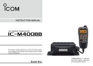
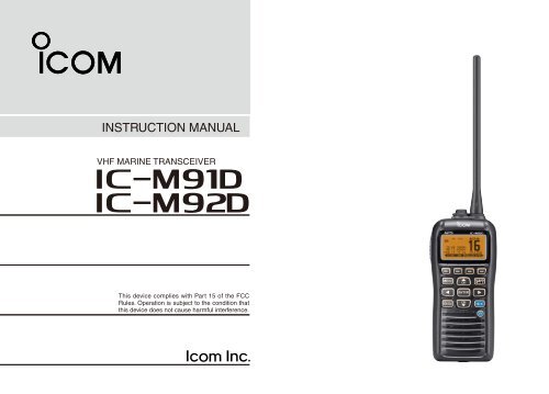
INSTRUCTION MANUAL<br />
VHF MARINE TRANSCEIVER<br />
i<strong>M91D</strong><br />
i<strong>M92D</strong><br />
CLEAR<br />
This device complies with Part 15 of the FCC<br />
Rules. Operation is subject to the condition that<br />
this device does not cause harmful interference.
FOREWORD<br />
Thank you for purchasing this Icom product. The <strong>IC</strong>-<strong>M91D</strong><br />
and <strong>IC</strong>-<strong>M92D</strong> VHF MARINE TRANSCEIVER are designed and built<br />
with Icom’s state of the art technology and craftsmanship.<br />
With proper care this radio should provide you with years of<br />
trouble-free operation.<br />
IMPORTANT<br />
READ ALL INSTRUCTIONS carefully and completely<br />
before using the transceiver.<br />
SAVE THIS INSTRUCTION MANUAL—This<br />
instruction manual contains important operating instructions<br />
for the <strong>IC</strong>-<strong>M91D</strong> and <strong>IC</strong>-<strong>M92D</strong>.<br />
This instruction manual includes some functions which are<br />
usable only when they are pre-programmed by your dealer.<br />
Ask your dealer for details.<br />
EXPL<strong>IC</strong>IT DEFINITIONS<br />
WORD<br />
RDANGER!<br />
RWARNING!<br />
CAUTION<br />
NOTE<br />
FEATURES<br />
DEFINITION<br />
Personal death, serious injury or an explosion<br />
may occur.<br />
Personal injury, fi re hazard or electric<br />
shock may occur.<br />
Equipment damage may occur.<br />
If disregarded, inconvenience only. No risk<br />
of personal injury, fire or electric shock.<br />
☞ Floats on water<br />
The transceiver floats in fresh or salt<br />
water even when the supplied accessories<br />
are attached.<br />
• When a third-party battery pack, strap, antenna,<br />
and so on is used, it may sink.<br />
☞ Floats and flashes<br />
When the transceiver detects that it has<br />
come in contact with water, the LCD<br />
backlight, keys and trim start to blink,<br />
making it easy to fi nd the transceiver<br />
even at night or in a dark environment.<br />
i
IN CASE OF EMERGENCY<br />
If your vessel requires assistance, contact other vessels and<br />
the Coast Guard by sending a distress call on Channel 16.<br />
Or, transmit your Distress call using digital selective calling<br />
on Channel 70.<br />
USING CHANNEL 16<br />
DISTRESS CALL PROCEDURE<br />
1. “MAYDAY MAYDAY MAYDAY.”<br />
2. “THIS IS ...............” (name of vessel).<br />
3. Say your call sign or other indication of the vessel (AND<br />
your 9-digit DSC ID, if you have one).<br />
4. “LOCATED AT ...............” (your position).<br />
5. State the nature of the distress and assistance required.<br />
6. Give any other information which might facilitate the<br />
rescue.<br />
USING DIGITAL SELECTIVE CALLING (Ch 70)<br />
DISTRESS CALL PROCEDURE<br />
1. While lifting up the key cover, hold down [DISTRESS] for<br />
3 seconds until you hear 3 short beeps and then one long<br />
beep.<br />
2. Wait for an acknowledgment on Channel 70 from a coast<br />
station.<br />
• After the acknowledgement is received, Channel 16 is<br />
automatically selected.<br />
3. Push and hold [PTT], then transmit the appropriate information<br />
as listed to the left.<br />
ii
RECOMMENDATION<br />
CLEAN THE TRANSCEIVER THOROUGHLY WITH FRESH<br />
WATER after exposure to saltwater. Otherwise, the transceiver's<br />
keys, switches and controllers may become inoperable<br />
due to salt crystallization.<br />
NOTE: DO NOT wash the transceiver in water if there is any<br />
reason to suspect the waterproofi ng may not be effective. For<br />
example, in cases where the battery pack rubber seal is damaged,<br />
the transceiver/battery pack is cracked or broken, or<br />
has been dropped, or when the battery pack is detached from<br />
the transceiver.<br />
PRECAUTIONS<br />
R WARNING! NEVER connect the transceiver to an<br />
AC outlet. This may pose a fi re hazard or result in an electric<br />
shock.<br />
R WARNING! NEVER hold the transceiver so that<br />
the antenna is very close to, or touching exposed parts of<br />
the body, especially the face or eyes, while transmitting. The<br />
transceiver will perform best if the microphone is 5 to 10 cm (2<br />
to 4 inches) away from the lips and the transceiver is vertical.<br />
R WARNING! NEVER operate the transceiver with<br />
other audio accessories at high volume levels. Hearing experts<br />
advise against continuous high volume operation. If you<br />
experience a ringing in your ears, reduce the volume level or<br />
discontinue use.<br />
DO NOT modify the transceiver. The transceiver warranty does<br />
not cover any problems caused by unauthorized modification.<br />
BE CAREFUL! The transceiver will become hot when<br />
operating it continuously for long periods of time.<br />
KEEP the transceiver and microphone at least 1 m (3.3 feet)<br />
away from the vessel’s magnetic navigation compass.<br />
KEEP the transceiver out of the reach of children.<br />
iii
PRECAUTIONS<br />
CAUTION: MAKE SURE the fl exible antenna, battery<br />
pack and jack cover are securely attached to the transceiver,<br />
and that the antenna and battery pack are dry before<br />
attachment. Exposing the inside of the transceiver to dust or<br />
water will result in serious damage to the transceiver.<br />
DO NOT operate the transceiver near unshielded electrical<br />
blast ing caps or in an explosive atmosphere.<br />
DO NOT push [PTT] when not actually intending to transmit.<br />
DO NOT use or place the transceiver in direct sunlight<br />
or in areas with temperatures below –20°C (–4°F) or above<br />
+60°C (+140°F), and for the Australian version, below –10°C<br />
or above +55°C (+140°F).<br />
The basic operations, transmission and reception of the<br />
transceiver are guaranteed within the specifi ed operating<br />
temperature range. However, the LCD display may not be<br />
operate correctly, or show an indication in the case of long<br />
hours of operation, or after being placed in extremely cold<br />
areas.<br />
DO NOT use harsh solvents such as benzine or alcohol<br />
when cleaning, as they will damage the transceiver surfaces.<br />
BE CAREFUL! The <strong>IC</strong>-<strong>M91D</strong> and <strong>IC</strong>-<strong>M92D</strong> meet IPX7*<br />
requirements for dust-tight and waterproof protection. However,<br />
once the transceiver has been dropped, dust-tight and<br />
waterproof protection cannot be guaranteed because of possible<br />
damage to the transceiver’s case or the waterproof<br />
seal.<br />
* Only when the jack cover or the optional HM-167 is attached.<br />
Even when the transceiver power is OFF, a slight current still<br />
fl ows in the circuits. Remove the battery pack or batteries<br />
from the trans ceiver when not using it for a long time. Otherwise,<br />
the installed battery pack or batteries will become exhausted,<br />
and will need to be recharged or replaced.<br />
BE CAREFUL! Even if the volume level is set low, the<br />
beeps of the Float ’n Flash, DSC alarm and AquaQuake functions<br />
are very loud.<br />
MAKE SURE to turn the transceiver power OFF before<br />
connect ing the supplied/optional equipment.<br />
For U.S.A. only:<br />
CAUTION: Changes or modifi cations to this transceiver, not<br />
expressly approved by Icom Inc., could void your authority to<br />
operate this transceiver under FCC regulations.<br />
iv
v<br />
FCC INFORMATION<br />
FOR CLASS B UNINTENTIONAL RADIATORS<br />
This equipment has been tested and found to comply with<br />
the limits for a Class B digital device, pursuant to part 15 of<br />
the FCC Rules. These limits are designed to provide reasonable<br />
protection against harmful interference in a residential<br />
installation. This equipment generates, uses and can radiate<br />
radio frequency energy and, if not installed and used in accordance<br />
with the instructions, may cause harmful interference<br />
to radio communications. However, there is no guarantee<br />
that interference will not occur in a particular installation.<br />
If this equipment does cause harmful interference to radio<br />
or television reception, which can be determined by turning<br />
the equipment off and on, the user is encouraged to try to<br />
correct the interference by one or more of the following measures:<br />
• Reorient or relocate the receiving antenna.<br />
• Increase the separation between the equipment and receiver.<br />
• Connect the equipment into an outlet on a circuit different<br />
from that to which the receiver is connected.<br />
• Consult the dealer or an experienced radio/TV technician<br />
for help.<br />
Icom, Icom Inc. and the Icom logo are registered trademarks of Icom Incorporated<br />
(Japan) in Japan, the United States, the United Kingdom, Germany,<br />
France, Spain, Russia and/or other countries.<br />
TABLE OF CONTENTS<br />
FOREWORD ......................................................................... i<br />
IMPORTANT .......................................................................... i<br />
EXPL<strong>IC</strong>IT DEFINITIONS ....................................................... i<br />
FEATURES ............................................................................ i<br />
IN CASE OF EMERGENCY ................................................. ii<br />
RECOMMENDATION .......................................................... iii<br />
PRECAUTIONS ................................................................... iii<br />
FCC INFORMATION ............................................................ v<br />
TABLE OF CONTENTS ........................................................ v<br />
1 OPERATING RULES ........................................................1<br />
2 SUPPLIED ACCESSORIES AND ATTACHMENTS .....2–3<br />
■ Supplied accessories ...................................................2<br />
■ Attachments .................................................................2<br />
3 PANEL DESCRIPTION .................................................4–9<br />
■ Front, top, side and rear panels ...................................4<br />
■ Softkeys .......................................................................6<br />
■ Function display ..........................................................7<br />
■ Softkey function............................................................9<br />
4 PREPARATION ...............................................................10<br />
■ MMSI code programming...........................................10<br />
5 BAS<strong>IC</strong> OPERATION .................................................11–16<br />
■ Channel selection ......................................................11<br />
■ Call channel programming .........................................13
TABLE OF CONTENTS<br />
■ Adjusting the volume level..........................................13<br />
■ Adjusting the squelch level.........................................13<br />
■ Receiving and transmitting.........................................14<br />
■ Lock function..............................................................15<br />
■ Monitor function .........................................................15<br />
■ AquaQuake water draining function ...........................15<br />
■ Backlight setting.........................................................15<br />
■ Channel name programming......................................16<br />
6 SCAN OPERATION ..................................................17–18<br />
■ Scan types ................................................................17<br />
■ Setting Favorite (TAG) channels ................................18<br />
■ Starting a scan...........................................................18<br />
7 DUALWATCH/TRI-WATCH .............................................19<br />
■ Description .................................................................19<br />
■ Operation ...................................................................19<br />
8 DSC OPERATION .....................................................20–70<br />
■ DSC address ID ........................................................20<br />
■ Position and time programming..................................23<br />
■ Distress call................................................................24<br />
■ Transmitting DSC calls...............................................28<br />
■ Receiving DSC calls ..................................................51<br />
■ Received Call log .......................................................63<br />
■ Transmitted Call log....................................................65<br />
■ DSC Settings .............................................................66<br />
9 OTHER FUNCTIONS ................................................71–81<br />
■ MOB (Man OverBoard) ..............................................71<br />
■ Waypoint ....................................................................74<br />
■ Navigation ..................................................................78<br />
■ Compass screen ........................................................80<br />
■ GPS status screen .....................................................81<br />
10 MENU SCREEN OPERATION ................................82–88<br />
■ Menu screen operation ..............................................82<br />
■ Menu screen items.....................................................83<br />
■ Radio Settings items ..................................................84<br />
■ Confi guration items ....................................................85<br />
11 BATTERY CHARGING ............................................89–93<br />
■ Battery caution ...........................................................89<br />
■ Regular battery charger .............................................91<br />
■ Optional battery chargers...........................................92<br />
12 OPTIONAL SPEAKER-M<strong>IC</strong>ROPHONE ........................94<br />
■ HM-167 descriptions ..................................................94<br />
■ Attachment.................................................................94<br />
13 TROUBLESHOOTING ...................................................95<br />
14 SPECIF<strong>IC</strong>ATIONS AND OPTIONS .........................96–97<br />
■ Specifi cations.............................................................96<br />
■ Options.......................................................................97<br />
15 VHF MARINE CHANNEL LIST .....................................98<br />
16 SAFETY TRAINING INFORMATION ....................99–100<br />
vi
1 OPERATING RULES<br />
D Priorities<br />
• Read all rules and regulations pertaining to priorities and<br />
keep an up-to-date copy handy. Safety and distress calls<br />
take priority over all others.<br />
• You must monitor Channel 16 when you are not operating<br />
on another channel.<br />
• False or fraudulent distress calls are prohibited under law.<br />
D Privacy<br />
• Information overheard but not intended for you cannot lawfully<br />
be used in any way.<br />
• Indecent or profane language is prohibited.<br />
D Radio licenses<br />
(1) SHIP STATION L<strong>IC</strong>ENSE<br />
You must have a current radio station license before using<br />
the transceiver. It is unlawful to operate a ship station which<br />
is not licensed.<br />
Inquire through your dealer or the appropriate government<br />
agency for a Ship-Radiotelephone license application. This<br />
government-issued license states the call sign which is your<br />
craft’s identifi cation for radio purposes.<br />
(2) OPERATOR’S L<strong>IC</strong>ENSE<br />
A Restricted Radiotelephone Operator Permit is the license<br />
most often held by small vessel radio operators when a radio<br />
is not required for safety purposes.<br />
The Restricted Radiotelephone Operator Permit must be<br />
posted or kept with the operator. Only a licensed radio operator<br />
may operate a transceiver.<br />
However, non-licensed individuals may talk over a transceiver<br />
if a licensed operator starts, supervises, ends the call and<br />
makes the necessary log entries.<br />
A current copy of the applicable government rules and regulations<br />
is only required to be on hand for vessels in which<br />
a radio telephone is compulsory. However, even if you are<br />
not required to have these on hand it is your responsibility to<br />
be thoroughly acquainted with all pertinent rules and regulations.<br />
NOTE: Even though the <strong>IC</strong>-<strong>M92D</strong> is capable of operation<br />
on VHF marine channels 3, 21, 23, 61, 64, 81, 82 and<br />
83, according to FCC regulations these simplex channels<br />
cannot be lawfully used by the general population in<br />
U.S.A. waters.<br />
1
SUPPLIED ACCESSORIES AND ATTACHMENTS<br />
2<br />
■ Supplied accessories<br />
Handstrap<br />
Battery pack<br />
Antenna<br />
Belt clip<br />
■ Attachments<br />
Battery charger<br />
(with 2 screws)<br />
D Flexible antenna<br />
Connect the supplied fl exible antenna<br />
to the antenna connector.<br />
CAUTION:<br />
• NEVER carry the transceiver by holding<br />
the antenna.<br />
• Transmitting without an antenna may<br />
damage the transceiver.<br />
AC adapter<br />
(Different type may be<br />
supplied, depending<br />
on the version)<br />
Cigarette lighter cable<br />
D Handstrap<br />
Pass the handstrap through<br />
the loop on the back side of<br />
the transceiver as illustrated<br />
at right. This facilitates carrying.<br />
D Belt clip<br />
Attach/detach the belt clip to the transceiver as illustrated<br />
below.<br />
To attach the belt clip<br />
To detach the belt clip<br />
w<br />
Be careful!<br />
Do not break<br />
your finger<br />
nails.<br />
q<br />
1<br />
2<br />
3<br />
4<br />
5<br />
6<br />
7<br />
8<br />
9<br />
10<br />
11<br />
12<br />
13<br />
14<br />
15<br />
16<br />
2
2 SUPPLIED ACCESSORIES AND ATTACHMENTS<br />
D Battery pack<br />
To remove the battery pack:<br />
Turn the screw counter clockwise one quarter turn, then pull<br />
the battery pack in the direction of the arrow, as shown below.<br />
To attach the battery pack:<br />
Insert the battery pack completely into the transceiver, then<br />
turn the screw clockwise one quarter turn.<br />
NEVER remove or insert the battery pack when the transceiver<br />
is wet or soiled. This may result water or dust getting<br />
into the transceiver or battery pack and may result in<br />
the transceiver being damaged.<br />
Screw position<br />
when removing battery<br />
NOTE: When removing or attaching the battery pack, use<br />
a coin or standard screwdriver to loosen or tighten the bottom<br />
screw.<br />
CAUTION:<br />
When attaching or removing a battery pack, make sure<br />
the rubber seal is set in the groove of the battery pack<br />
correctly. If the seal is not correctly in the groove, it may<br />
be damaged when attaching the battery pack. If the seal is<br />
damaged, waterproof protection is not guaranteed.<br />
NOTE:<br />
When attaching a battery pack, make sure dust or other<br />
material does not adhere to the rubber seal. If dust or other<br />
material is on the seal when attaching a battery pack,<br />
waterproof protection may not be guaranteed.<br />
Make sure the rubber seal is properly seated in the<br />
groove and dust or other material does not adhere to it.<br />
Screw position<br />
when attaching battery<br />
Correct position<br />
Incorrect position<br />
Battery pack<br />
Rubber seal<br />
Groove<br />
Battery pack<br />
3
PANEL DESCRIPTION<br />
3<br />
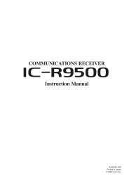
■ Front, top, side and rear panels<br />
q<br />
w<br />
e<br />
r<br />
t<br />
y<br />
Speaker<br />
<br />
Distress key<br />
(p. 24)<br />
Function<br />
display<br />
(pp. 7, 8, 9)<br />
!2<br />
!1<br />
!0<br />
o<br />
i<br />
u<br />
Microphone<br />
q ANTENNA CONNECTOR (p. 2)<br />
Connects to the supplied antenna.<br />
w SPEAKER-M<strong>IC</strong>ROPHONE CONNECTOR [SP M<strong>IC</strong>] (p. 94)<br />
Connects to the optional external speaker-microphone.<br />
NOTE: Attach the [SP M<strong>IC</strong>] cap when the optional<br />
speaker-microphone is not used. Otherwise, water will<br />
get into the transceiver.<br />
e PTT SWITCH [PTT]<br />
Hold down to transmit; release to receive. (p. 14)<br />
r MENU KEY<br />
Push to enter or exit the Menu screen.<br />
t LEFT AND RIGHT KEYS [Ω]/[≈]<br />
➥ Push to switch to the previous or next key function that<br />
is assigned to the softkeys. (p. 9)<br />
➥ Push to select the desired character or number in the<br />
table while in the channel name, position, MMSI code<br />
programming mode, and so on. (pp. 10, 16, 23)<br />
y VOLUME/SQUELCH KEY [VOL/SQL]<br />
➥ Push to enter the volume level adjustment mode.<br />
(p. 13)<br />
➥ Push again while in the volume level adjustment mode<br />
to enter the squelch level adjustment mode.<br />
➥ Hold down for 1 second to activate the monitor function.<br />
(p. 15)<br />
u POWER KEY [ ]<br />
Hold down for 1 second to turn the power ON or OFF.<br />
1<br />
2<br />
3<br />
4<br />
5<br />
6<br />
7<br />
8<br />
9<br />
10<br />
11<br />
12<br />
13<br />
14<br />
15<br />
16<br />
4
3 PANEL DESCRIPTION<br />
■ Front, top and rear panels (Continued)<br />
q<br />
w<br />
e<br />
r<br />
t<br />
y<br />
Speaker<br />
<br />
Distress key<br />
(p. 24)<br />
Function<br />
display<br />
(pp. 7, 8, 9)<br />
!2<br />
!1<br />
!0<br />
o<br />
i<br />
u<br />
Microphone<br />
i CHANNEL 16 KEY [16/C]<br />
➥ Push to select Channel 16. ( p. 11)<br />
➥ Hold down for 1 second to select the Call channel.<br />
(p. 11)<br />
➥ Hold down for 3 seconds to enter the Call channel<br />
programming mode when the Call channel is selected.<br />
(p. 13)<br />
o ENTER KEY<br />
Push to set the input data, selected item, and so on.<br />
!0 CLEAR/LOCK KEY [ ]<br />
➥ Push to cancel the entered data, or to return to the previous<br />
screen.<br />
➥ Hold down for 1 second to turn the key lock function ON<br />
or OFF. (p. 15)<br />
!1 UP AND DOWN/CHANNEL SELECT KEYS [∫•CH]/[√•CH]<br />
➥ Push to select the operating channels, Menu items,<br />
Menu settings, and so on. (p. 82)<br />
➥ Push to check Favorite (TAG) channels, change the<br />
scanning direction or manually resume a scan. (p. 18)<br />
!2 SOFTKEYS<br />
Slide the menu by pushing the [Ω]/[≈] keys, then push either<br />
of the 4 softkeys to select a menu displayed at the<br />
bottom of the LCD display.<br />
See Softkeys on the next page for more details. (p. 6)<br />
5
PANEL DESCRIPTION<br />
3<br />
■ Softkeys<br />
The desired functions as described below can be assigned<br />
in the Menu screen.<br />
Scan [ ] (p. 17)<br />
Push to start or stop a Normal or Priority scan.<br />
Dualwatch/Tri-watch [ ] (p. 19)<br />
➥ Push to start a Dualwatch or Tri-watch.<br />
➥ Push to stop a Dualwatch or Tri-watch when either is<br />
activated.<br />
High/Low [ ] (p. 14)<br />
Push to set the power to high or low.<br />
• Some channels are set to only low power.<br />
Channel/Weather Channel [ ] (p. 11)<br />
Push to select either the regular channels or the Weather<br />
channels.<br />
AquaQuake [ ] (p. 15)<br />
While holding down, the AquaQuake function is activated<br />
to clear water away from the speaker grill.<br />
Favorite channel [ ] (p. 18)<br />
➥ Push to set or clear the displayed channel as a Favorite<br />
(Tag) channel.<br />
➥ Hold down for 3 seconds to clear or set all Favorite<br />
channels in the selected channel group.<br />
Name [ ] (p. 16)<br />
Push to enter the channel name programming mode.<br />
Backlight [ ] (p. 15)<br />
Push to enter the LCD and key backlight brightness adjustment<br />
mode.<br />
• While in the adjustment mode, push [∫]/[√][Ω]/[≈] to adjust the<br />
brightness of the LCD and key backlight.<br />
MOB [ ] (p. 71)<br />
➥ Push to enter “MOB” in the menu screen.<br />
➥ Hold down for 1 second to memorize the current position<br />
as the MOB (Man OverBoard) point.<br />
Waypoint [ ] (p. 74)<br />
➥ Push to enter “WAYPOINT” in the menu screen.<br />
➥ Hold down for 1 second to memorize the current position<br />
as a Waypoint.<br />
1<br />
2<br />
3<br />
4<br />
5<br />
6<br />
7<br />
8<br />
9<br />
10<br />
11<br />
12<br />
13<br />
14<br />
15<br />
16<br />
6
3 PANEL DESCRIPTION<br />
■ Softkeys (Continued)<br />
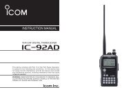
■ Function display<br />
Navigation [ ] (p. 78)<br />
After holding down [MOB], or in the MOB or Waypoint list<br />
screen, push this key to start navigating to the selected<br />
position.<br />
Compass [ ] (p. 80)<br />
Push to display the compass screen to show the vessel’s<br />
course heading, SOG (Speed Over Ground) and COG<br />
(Course Over Ground).<br />
!7<br />
!6<br />
!5<br />
!4<br />
!3<br />
q<br />
w e r t y u i<br />
o<br />
!0<br />
!1<br />
!2<br />
Log [ ] (p. 63)<br />
Push to enter “RCVD CALL LOG” in the DSC CALLS menu.<br />
q BUSY/TRANSMIT IND<strong>IC</strong>ATOR (p. 14)<br />
➥ “BUSY” appears when receiving a signal or when the<br />
squelch opens.<br />
➥ “TX” appears while transmitting.<br />
➥ “MONI” appears while the monitor function is activated.<br />
w POWER <strong>IC</strong>ON (p. 14)<br />
➥ “HI” appears when high power is selected.<br />
➥ “LOW” appears when low power is selected.<br />
e CHANNEL GROUP <strong>IC</strong>ON/ WEATHER CHANNEL (p. 12)<br />
➥ The selected channel group icon is displayed as U.S.A.<br />
“USA,” International “INT,” Canadian “CAN” or weather<br />
channel “WX,” depending on the transceiver version.<br />
r CALL CHANNEL <strong>IC</strong>ON (p. 11)<br />
Appears when Call channel is selected.<br />
7
PANEL DESCRIPTION<br />
3<br />
t DUPLEX <strong>IC</strong>ON (p. 12)<br />
Appears when a duplex channel is selected.<br />
y FAVORITE CHANNEL <strong>IC</strong>ON (p. 18)<br />
Appears while a Favorite (TAG) channel is selected.<br />
u MAIL <strong>IC</strong>ON (p. 51)<br />
Blinks when there is an unread message.<br />
i GPS <strong>IC</strong>ON<br />
➥ Stays ON while the GPS data is received, and a valid<br />
position is received.<br />
➥ Blinks when an invalid position is being received.<br />
o SWITCH <strong>IC</strong>ON (p. 67)<br />
Appears when the “CH 16 SWITCH” in DSC Settings is set<br />
to ‘OFF.’<br />
!0 LOCK <strong>IC</strong>ON (p. 15)<br />
Appears while the lock function is activated.<br />
!1 CHANNEL NUMBER READOUT<br />
Shows the selected operating channel number.<br />
• When a simplex channel is selected, “A” appears.<br />
!2 CHANNEL NAME FIELD (p. 16)<br />
➥ The channel name appears, if programmed.<br />
➥ “DSC CHECK” blinks while receiving on CH70.<br />
!3 KEY <strong>IC</strong>ON (p. 9)<br />
Shows the programmed function of the softkeys on the<br />
front panel.<br />
!4 TIME ZONE IND<strong>IC</strong>ATOR<br />
➥ Shows the current time when GPS data is received, or<br />
the time is manually programmed.<br />
• “??” will blink when invalid GPS data is received for 30<br />
seconds.<br />
• “??” will blink when manually input GPS data is no longer<br />
valid after 4 hours, and then “NO TIME” will appear after<br />
23.5 hours.<br />
➥ “LOCAL” appears when the offset time is set.<br />
➥ “NO TIME” appears when no GPS data is received and<br />
no time data is manually input.<br />
➥ “MNL” appears when the time is manually programmed.<br />
1<br />
2<br />
3<br />
4<br />
5<br />
6<br />
7<br />
8<br />
9<br />
10<br />
11<br />
12<br />
13<br />
14<br />
15<br />
16<br />
8
3 PANEL DESCRIPTION<br />
■ Function Display (Continued)<br />
!5 POSITION IND<strong>IC</strong>ATOR<br />
➥ Shows the current position when valid GPS data is received<br />
or the position is manually programmed.<br />
• “??” will blink when invalid GPS data is received for 30<br />
seconds.<br />
• “??” will blink when manually input GPS data is no longer<br />
valid after 4 hours, and then “NO POSITION” will appear<br />
after 23.5 hours.<br />
• “NO POSITION” is displayed when no GPS data is received<br />
since the transceiver power turned ON.<br />
• “NO POSITION” appears when no GPS data is received,<br />
and no position is manually input.<br />
!6 SCAN IND<strong>IC</strong>ATOR<br />
➥ “SCAN 16” is displayed during a Priority scan; “SCAN”<br />
appears during a Normal scan. (p. 17)<br />
➥ “DUAL 16” appears during Dualwatch; “TRI 16” appears<br />
during Tri-watch. (p. 19)<br />
!7 BATTERY IND<strong>IC</strong>ATOR<br />
Shows the battery’s remaining power.<br />
Indication<br />
Battery level<br />
Full Middle Charging<br />
required<br />
blinks when the battery is over charged.<br />
No battery<br />
■ Softkey function<br />
Various functions can be assigned to the softkeys.<br />
When the key function is assigned, the key icon is displayed<br />
above the softkeys, as shown below.<br />
D Softkey function selection<br />
When “Ω” or “≈” is displayed beside the key icon, pushing [Ω]<br />
or [≈] sequentially displays the previous or next key function<br />
that is assigned to the softkey.<br />
Push<br />
*<br />
*Push this key to start or stop a scan.<br />
Push<br />
The order of the key icons may differ, depending on the<br />
preprogramming.<br />
9
PREPARATION<br />
4<br />
■ MMSI code programming<br />
The 9 digit MMSI (Maritime Mobile Service Identity: DSC self<br />
ID) code can be programmed at power ON.<br />
This initial code setting can be performed only once.<br />
After being set, it can be changed by only your dealer<br />
or distributor. If your MMSI code has already been programmed,<br />
this programming is not necessary.<br />
q Hold down [ ] to turn ON the power.<br />
• Three short beeps sound, and “NO DSC MMSI” is displayed.<br />
w Push [ENTER] to start the MMSI code programming.<br />
• Push [CLEAR] twice to cancel the programming, and go to the<br />
normal operating screen. In this case, the transceiver cannot<br />
make a DSC call. To program the MMSI code, turn OFF the<br />
power, then turn it ON again.<br />
e Enter your MMSI code in the following manner:<br />
• Select a desired number using [∫]/[√]/[Ω]/[≈].<br />
• Push [ENTER] to set it.<br />
• To move the cursor, select either arrow, “←” or “→,” then push<br />
[ENTER].<br />
r Repeat step e to enter all 9 digits.<br />
t After entering the 9 digit code, “FINISH” is automatically<br />
selected, and then push [ENTER] to set it.<br />
y The “MMSI CONFIRMATION” screen is displayed.<br />
u Enter your MMSI code again for confirmation.<br />
• Enter in the same manner as steps e through t.<br />
i When your MMSI code programming is successfully completed,<br />
the screen as shown below is briefl y displayed.<br />
• After that, the normal operating screen is displayed.<br />
The programmed MMSI code can be checked in the MENU<br />
screen. (p. 83)<br />
1<br />
2<br />
3<br />
4<br />
5<br />
6<br />
7<br />
8<br />
9<br />
10<br />
11<br />
12<br />
13<br />
14<br />
15<br />
16<br />
10
5 BAS<strong>IC</strong> OPERATION<br />
■ Channel selection<br />
IMPORTANT: Prior to using the transceiver for the fi rst<br />
time, the battery pack must be fully charged for optimum<br />
life and operation. To avoid damage to the transceiver,<br />
turn the power OFF while charging.<br />
D Channel 16<br />
Channel 16 is the distress and safety channel. It is used for<br />
establishing initial contact with a station and for emergency<br />
communications. Channel 16 is monitored during both Dual-watch<br />
and Tri-watch. While in the standby condition, you<br />
must monitor Channel 16.<br />
q Push [16/C] to select Channel 16.<br />
w Push [ CH/WX] to return to the selected channel before<br />
Channel 16, or push [∫](CH) or [√](CH) to select an operating<br />
channel.<br />
D Call channel<br />
Each regular channel group has separate leisure-use call<br />
channels. The call channel is monitored during Tri-watch.<br />
The call channels can be programmed and are used to store<br />
your most often used channel in each channel group for quick<br />
recall. (p. 13)<br />
q Hold down [16/C] for 1 second to select Call channel.<br />
• “CALL” and the call channel number are displayed.<br />
• Call channel can be re-programmed. See the “Call channel programming”<br />
on page 13 for details.<br />
w Select [CH/WX] to return to the selected channel before<br />
the call channel, or push [∫](CH) or [√](CH) to select the<br />
operating channel.<br />
Hold down [16/C] key<br />
for 1 second<br />
Push [16/C] key<br />
11
BAS<strong>IC</strong> OPERATION<br />
5<br />
D Channel group selection<br />
There are preprogrammed U.S.A. channels, International<br />
channels and Canadian* channels. These channel groups<br />
may be specifi ed for the operating area.<br />
* For only the U.S.A. and EXP transceiver versions.<br />
q Push [MENU].<br />
w Push [ Y]/[Z] to select “Radio Settings”.<br />
e Push [ Y]/[Z] to select “CHAN Group”, and then push [EN-<br />
TER].<br />
r Push [Y]/[Z] to select the desired channel group, and then<br />
push [ENTER].<br />
• U.S.A. (USA), International (INT) and Canadian (CAN) channel<br />
groups can be selected.<br />
t Push [EXIT] to exit the Menu screen.<br />
y Push [Y](CH)/[Z](CH) to select a channel.<br />
• “DUP” appears for duplex channels.<br />
• “A” appears for simplex channel.<br />
D Weather channels<br />
The transceiver has 10 pre-programmed weather channels.<br />
These are used for monitoring broadcasts from NOAA (National<br />
Oceanographic and Atmospheric Administration.) The<br />
transceiver can automatically detect a weather alert tone on<br />
the selected weather channel or while scanning. (p. 17)<br />
To Select a Weather channel:<br />
Push [CH/WX] to select a weather channel.<br />
• “WX” is displayed when a weather channel is selected.<br />
• The Weather channel alert icon appears when the alert function<br />
is turned ON.<br />
To set the Weather Alert:<br />
q Push [MENU].<br />
w Push [ Y]/[Z] to select “Radio Settings” and then push<br />
[ENTER].<br />
e Select “WX Alert” and then push [ENTER].<br />
r Select “ON” or “ON with Scan” to set the Weather Alert.<br />
t Push [EXIT] to exit the Menu screen.<br />
• WX Alert icon appears.<br />
1<br />
2<br />
3<br />
4<br />
5<br />
6<br />
7<br />
8<br />
9<br />
10<br />
11<br />
12<br />
13<br />
14<br />
15<br />
16<br />
12
5 BAS<strong>IC</strong> OPERATION<br />
■ Call channel programming<br />
You can program the call channel with your most often-used<br />
channels in each channel group for quick recall.<br />
q Select the desired U.S.A., <strong>Canada</strong> or International channel<br />
group to be programmed. (p. 12)<br />
w Hold down [16/C] for 1 second to select the call channel of<br />
the selected channel group.<br />
• “CALL” and call channel number are displayed.<br />
e Hold down [16/C] again for 3 seconds until long beep stops<br />
with two short beeps.<br />
• The channel programming mode screen is displayed.<br />
r Push [Y](CH)/[Z](CH) to select the desired channel.<br />
t Push [ENTER] to program the selected channel as the call<br />
channel.<br />
• The display automatically returns to the normal operating mode.<br />
■ Adjusting the volume level<br />
The volume level can be adjusted with [VOL/SQL] and [∫]/<br />
[√]/[Ω]/[≈] keys.<br />
q Push [VOL/SQL] once to enter the volume adjustment<br />
mode, then adjust the volume level with [∫]/[√] or [Ω]/[≈].<br />
•The transceiver has 20 volume levels and OFF.<br />
• If no key operation is performed for 5 seconds, the transceiver<br />
sets the selected level, and returns to the normal mode.<br />
w Push [ENTER] to set, and exit the volume adjustment mode.<br />
• Push [CLEAR] to cancel.<br />
■ Adjusting the squelch level<br />
The squelch level can be adjusted with [VOL/SQL] and [∫]/<br />
[√]/[Ω]/[≈] keys.<br />
In order to receive signals properly, as well as for the scan<br />
to function effectively, the squelch must be adjusted to its<br />
proper level.<br />
q Push [VOL/SQL] twice to enter the squelch adjustment<br />
mode, then adjust the squelch level with [∫]/[√] or [Ω]/[≈].<br />
• The transceiver has 11 squelch levels: OPEN is completely<br />
open, 10 is tight squelch and 1 is loose squelch.<br />
• If no key operation is performed for 5 seconds, the transceiver<br />
sets the selected level, and returns to the normal mode.<br />
w Push [ENTER] to set, and exit the squelch adjustment mode.<br />
• Push [CLEAR] to cancel.<br />
13
BAS<strong>IC</strong> OPERATION<br />
5<br />
■ Receiving and transmitting<br />
CAUTION: Transmitting without an antenna will damage<br />
the transceiver.<br />
q Hold down [ ] for 1 second to turn power ON.<br />
w Set the volume and squelch levels with [VOL/SQL].<br />
e Push [Y](CH)/[Z](CH) to select the desired channel.<br />
• Further adjustment of the audio may be necessary at this point.<br />
r Select [HI/LO] to select the output power if necessary.<br />
• “HI” appears when high power is selected; “LOW” when low<br />
power is selected.<br />
• Choose low power for short range communications, choose<br />
high power for longer distance communications.<br />
• Some channels are for low power only.<br />
t Hold down [PTT] to transmit, then speak into the microphone.<br />
• “TX” appears.<br />
• Channel 70 cannot be used for transmission.<br />
y Release [PTT] to receive.<br />
✓ Information<br />
➥ The Noise Cancel function reduces random noise components<br />
in the transmit and/or receive signal. See page<br />
86 for details<br />
➥ The transceiver monitors channel 70 every specifi c<br />
time period even when standing by on an operating<br />
channel.<br />
• “DSC CHECK” is displayed when channel 70 is busy.<br />
• The channel 70 monitoring confi guration can be changed in<br />
DSC Settings. See page 69 for details.<br />
IMPORTANT: To maximize the readability of your transmitted<br />
signal, pause a few seconds after pushing [PTT], hold<br />
the microphone 5 to 10 cm (2 to 4 inches) from your mouth<br />
and speak into the microphone at a normal voice level.<br />
NOTE: The transceiver has a power save function to conserve<br />
battery power. The power save function is activated<br />
automatically when no signal is received for 5 seconds.<br />
To prevent accidental prolonged transmission, the transceiver<br />
has a time-out timer function. This timer cuts a<br />
transmission OFF after 5 minutes of continuous transmission.<br />
t<br />
y<br />
w<br />
r<br />
e<br />
q<br />
Microphone<br />
1<br />
2<br />
3<br />
4<br />
5<br />
6<br />
7<br />
8<br />
9<br />
10<br />
11<br />
12<br />
13<br />
14<br />
15<br />
16<br />
14
5 BAS<strong>IC</strong> OPERATION<br />
15<br />
■ Lock function<br />
This function electronically locks all keys (except for [PTT],<br />
[DISTRESS] and [ ]) to prevent accidental channel changes<br />
and function access.<br />
➥ Push [CLEAR/ ] for 1 second to turn the lock function<br />
ON and OFF.<br />
• The lock function is automatically released when DSC call is<br />
received, or [DISTRESS] is pushed.<br />
■ Monitor function<br />
Displayed when<br />
the lock function<br />
is activated.<br />
The Monitor function opens the squelch by holding down<br />
[VOL/SQL] for 1 second.<br />
• “ ” appears while the function is activated.<br />
The function can be set to “PUSH” or “HOLD” in the following<br />
manner.<br />
q Select “Configuration” in the “MENU” screen.<br />
w Select “Monitor” to enter the “Push” or “Hold” selecting mode.<br />
• Push: The monitor function is activated by holding down [VOL/SQL]<br />
for 1 second. The squelch opens while holding down the key.<br />
• Hold: The monitor function is activated by holding down [VOL/<br />
SQL] for 1 second. The squelch stays open until any key<br />
is pushed.<br />
■ AquaQuake water draining<br />
function<br />
The AquaQuake water draining function clears water away<br />
from the speaker grill. Without this function, water may muffl e<br />
the sound coming from the speaker. The transceiver emits a<br />
vibrating beep when this function is activated.<br />
➥ While holding down [AQUA], the AquaQuake function is activated<br />
to clear water away from the speaker grill.<br />
• Beep sounds, regardless of the volume level setting.<br />
• Activates for 10 seconds in maximum to drain water.<br />
• The transceiver never accepts key operation while the Aqua-<br />
Quake function is activated.<br />
• The AquaQuake function can not be activated when an optional<br />
speaker-microphone is connected.<br />
■ Backlight setting<br />
This function lights the function display and keys, and it is<br />
convenient for night-time operation.<br />
q Select [BKLT] to enter the backlight adjusting mode.<br />
w Push [∫]/[√] or [Ω]/[≈] to adjust the brightness level between<br />
1(minimum) to 7 (maximum) or OFF.<br />
• The default setting is 4.<br />
• The display returns automatically to the main menu after 5 seconds<br />
without no key operation is been performed.<br />
• The backlight automatically turns OFF when no key operation<br />
is performed for 5 seconds.
BAS<strong>IC</strong> OPERATION<br />
5<br />
■ Channel name programming<br />
Each channel can be assigned a unique alphanumeric ID of<br />
up to 10 characters.<br />
Capital letters, 0 to 9, some symbols (! " # $ % & ' ( ) * + , – .<br />
/ [ \ ] ^ _ : ; < = > ?) and space can be used.<br />
q Push [ ∫](CH) or [√](CH) to select a channel.<br />
• First, cancel the Dualwatch, Tri-watch or Scan function, if activated.<br />
w Push [NAME] to open the channel name programming<br />
screen.<br />
• A black box is displayed on the fi rst character.<br />
e Enter the desired channel name in the following manner:<br />
• Select a desired character using [∫]/[√]/[Ω]/[≈].<br />
• Push [ENTER].<br />
• To move the cursor, select either arrow, “←” or “→,” then push<br />
[ENTER].<br />
• Select “SPACE,” then push [ENTER] to input a space.<br />
• Select “DELETE,” then push [ENTER] to delete a character.<br />
• Push [CLEAR] to cancel and return to the previous screen.<br />
r Repeat step<br />
e to input all characters.<br />
t Push [ Ω]/[≈]/[∫]/[√] to select “FINISH,” then push [EN-<br />
TER] to set and return to the previous screen.<br />
1<br />
2<br />
3<br />
4<br />
5<br />
6<br />
7<br />
8<br />
9<br />
10<br />
11<br />
12<br />
13<br />
14<br />
15<br />
16<br />
16
6 SCAN OPERATION<br />
■ Scan types<br />
Scanning is an effi cient way to locate signals quickly over a<br />
wide frequency range. The transceiver has both priority scan<br />
and normal scan.<br />
When the Weather Alert function is turned ON, the weather<br />
channel is also checked while scanning. (p. 85)<br />
PRIORITY SCAN<br />
CH 01<br />
CH 02<br />
Set the Favorite channels (scanned channels) before scanning.<br />
Clear the Favorite for unwanted channels which inconveniently<br />
stop scanning, such as those for digital communications.<br />
Choose the desired scan type from “Priority” or “Normal” in<br />
the set mode. (p. 84)<br />
NORMAL SCAN<br />
CH 01 CH 02<br />
WX*<br />
CH 16<br />
CH 03<br />
WX*<br />
CH 03<br />
CH 05 CH 04<br />
* When the weather alert function is activated.<br />
Priority scan sequentially searches through all<br />
Favorite channels while monitoring Channel 16.<br />
When a signal is detected on Channel 16, scan<br />
pauses until the signal disappears; when a signal is<br />
detected on a channel other than Channel 16, scan<br />
becomes Dualwatch until the signal disappears.<br />
CH 05 CH 04<br />
* When the weather alert function is activated.<br />
Normal scan, like Priority scan, searches through all<br />
Favorite channels in sequence. However, unlike Priority<br />
scan, Channel 16 is not checked unless Channel 16 is<br />
set as a Favorite channel.<br />
17
SCAN OPERATION<br />
6<br />
■ Setting Favorite channels<br />
For more effi cient scanning, add the desired channels as Favorite<br />
channels, or clear “ ” for unwanted channels.<br />
Channels that are not tagged will be skipped while scanning.<br />
Favorite channels can be independently assigned to each<br />
channel group (U.S.A., International and <strong>Canada</strong>*).<br />
* For only the U.S.A. and EXP transceiver versions.<br />
q Select the desired channel group. (p. 12)<br />
w Select the desired channel to be set as a Favorite channel.<br />
e Push [ ] to set the displayed channel as a Favorite channel.<br />
• “ ”appears on the display.<br />
r To cancel the Favorite channel setting, repeat step e.<br />
• “ ”disappears.<br />
✓ Clearing (or setting) all tagged channels<br />
Hold down [] for 3 seconds (until a long beep changes to<br />
2 short beeps) to clear all Favorite channel settings in the<br />
selected channel group.<br />
• Repeat above procedure to set all channels as Favorite channels.<br />
[Example]: Starting a Normal scan.<br />
Push<br />
[SCAN]<br />
■ Starting a scan<br />
First, set the scan type (Priority or Normal scan), WX Alert function<br />
and scan resume timer in the Menu screen. (pp. 84, 85)<br />
q Select the desired channel group. (p. 12)<br />
w Set the Favorite channels, as described to the left.<br />
e Make sure the squelch is closed to start a scan.<br />
r Push [SCAN] to start a Priority or Normal scan.<br />
• “SCAN 16” appears during a Priority scan; “SCAN” appears<br />
during a Normal scan.<br />
• When a signal is detected, the scan pauses until the signal<br />
disappears, or resumes after pausing 5 seconds, depending<br />
on the setting. (Channel 16 is still monitored during a Priority<br />
scan.)<br />
• Push [Y]/[Z] check the scanning Favorite channels, change<br />
the scanning direction or manually resume the scan.<br />
• A beep tone sounds and “16” blinks when a signal is received<br />
on Channel 16 during a Priority scan.<br />
t To stop the scan, push [CLEAR] or repeat step r.<br />
Scan starts.<br />
When a signal is received.<br />
1<br />
2<br />
3<br />
4<br />
5<br />
6<br />
7<br />
8<br />
9<br />
10<br />
11<br />
12<br />
13<br />
14<br />
15<br />
16<br />
18
7 DUALWATCH/TRI-WATCH<br />
■ Description<br />
Dualwatch monitors Channel 16 while you are receiving on<br />
another channel; Tri-watch monitors Channel 16 and the<br />
call channel while receiving another channel. Dualwatch/Triwatch<br />
is convenient for monitoring Channel 16 when you are<br />
operating on another channel.<br />
DUALWATCH/TRI-WATCH SIMULATION<br />
Call<br />
channel<br />
Ch 16 Ch 88 Ch 88 Ch 16 Ch 88 Ch 9<br />
■ Operation<br />
q Select Dualwatch or Tri-watch in the Menu screen. (p. 84)<br />
w Push [ Y](CH) or [Z](CH) to select the desired operating<br />
channel.<br />
e Push [DW] to start a Dualwatch or Tri-watch scan.<br />
• “DUAL 16” appears during Dualwatch; “TRI 16” appears during<br />
Tri-watch.<br />
• A beep tone sounds when a signal is received on Channel 16.<br />
r To cancel Dualwatch or Tri-watch, push [DW] again.<br />
[Example]: Operating Tri-watch on INT Channel 25.<br />
Tri-watch starts.<br />
Signal is received<br />
on Call channel.<br />
Dualwatch<br />
Tri-watch<br />
• If a signal is received on Channel 16, Dualwatch/Tri-watch<br />
pauses on Channel 16 until the signal disappears.<br />
• If a signal is received on the call channel during Tri-watch,<br />
Tri-watch becomes Dualwatch until the signal disappears.<br />
• To transmit on the selected channel during Dualwatch/<br />
Tri-watch, hold down [PTT].<br />
Tri-watch resumes after<br />
the signal disappears.<br />
Signal received on Channel<br />
16 takes priority.<br />
19
DSC OPERATION<br />
8<br />
■ DSC address ID<br />
D Programming Individual ID<br />
A total of 100 DSC address IDs can be programmed and assigned<br />
a name of up to 10 characters.<br />
q Enter “INDIVIDUAL ID” in the DSC SETTINGS menu.<br />
❮MENU❯ ➪ ❮DSC Settings ❯ ➪ ❮Individual ID❯<br />
(Push [MENU]) (Push [Y]/[Z], then push [ENTER].)<br />
w Push [ADD].<br />
• The “INDIVIDUAL ID” program screen is displayed.<br />
e Enter a desired individual ID in the following way:<br />
• Select a desired number using [Ω]/[≈].<br />
• Push [ENTER] to set it.<br />
• To move the cursor, select either arrow, “←” or “→,” then push<br />
[ENTER].<br />
The fi rst digit is specifi ed as ‘0’ for a Group ID.<br />
The fi rst two digits are ‘0’ for any Coast station ID.<br />
r Repeat step<br />
e to enter all 9 digits.<br />
t After entering the 9 digit code, push [ENTER] to set it.<br />
• The ID name programming screen is displayed.<br />
y Enter a desired 10 digit ID name in the following way:<br />
• Select a desired character using [∫]/[√]/[Ω]/[≈].<br />
• Push [ENTER] to set it.<br />
• To move the cursor, select either arrow, “←” or “→,” then push<br />
[ENTER].<br />
• Push [123] then [!$?] then [ABC] to select a character group.<br />
u After entering the ID name, push [ ∫]/[√]/[Ω]/[≈] to select<br />
“FINISH,” then push [ENTER] to program it.<br />
• The “INDIVIDUAL ID” list screen is displayed.<br />
i Push [MENU] to exit the MENU screen.<br />
1<br />
2<br />
3<br />
4<br />
5<br />
6<br />
7<br />
8<br />
9<br />
10<br />
11<br />
12<br />
13<br />
14<br />
15<br />
16<br />
20
New2001<br />
New<br />
8 DSC OPERATION<br />
D Programming Group ID<br />
q Enter “GROUP ID” in the DSC SETTINGS menu.<br />
❮MENU❯ ➪ ❮DSC Settings❯ ➪ ❮Group ID❯<br />
(Push [MENU]) (Push [Y]/[Z], then push [ENTER].)<br />
t After entering the 9 digit code, push [ENTER] to set it.<br />
• The Group ID name programming screen is displayed.<br />
w Push [ADD].<br />
• The “GROUP ID” program screen is displayed.<br />
e Enter a desired group ID in the following way:<br />
• Select a desired number using [Ω]/[≈].<br />
• Push [ENTER] to set it.<br />
• To move the cursor, select either arrow, “←” or “→,” then push<br />
[ENTER].<br />
The fi rst digit is fi xed as ‘0’ for a Group ID.<br />
The fi rst two digits are ‘0’ for any Coast station ID.<br />
r Repeat step<br />
e to input the specifi c 9 digits group code.<br />
y Enter a desired 10 digit ID name in the following way:<br />
• Select a desired character using [∫]/[√]/[Ω]/[≈].<br />
• Push [ENTER] to set it.<br />
• To move the cursor, select either arrow, “←” or “→,” then push<br />
[ENTER].<br />
• Push [123], [!$?] or [ABC] to select a character group.<br />
u After entering the ID name, push [ ∫]/[√]/[Ω]/[≈] to select<br />
“FINISH,” then push [ENTER] to program it.<br />
• The “GROUP ID” list screen is displayed.<br />
i Push [MENU] to exit the MENU screen.<br />
21
New2001<br />
DSC OPERATION<br />
8<br />
D Deleting Individual/Group ID<br />
q Enter “INDIVIDUAL ID” or “GROUP ID” in the DSC SET-<br />
TINGS menu.<br />
❮MENU❯ ➪ ❮DSC Settings❯ ➪ ❮Individual ID❯/❮Group ID❯<br />
(Push [MENU]) (Push [Y]/[Z], then push [ENTER].)<br />
• When no address ID is programmed, “No ID” is displayed. In this<br />
case, push [MENU] to exit the MENU screen.<br />
w Push [ Y]/[Z] to select a desired ID name, then push<br />
[DEL].<br />
e Push [OK] to delete the ID, and return to the “INDIVIDUAL<br />
ID” or “GROUP ID” list screen.<br />
• Push [CANCEL] to cancel it.<br />
r Push [MENU] to exit the MENU screen.<br />
1<br />
2<br />
3<br />
4<br />
5<br />
6<br />
7<br />
8<br />
9<br />
10<br />
11<br />
12<br />
13<br />
14<br />
15<br />
16<br />
22
New2001<br />
New<br />
8 DSC OPERATION<br />
■ Position and time programming<br />
A Distress call should include the ship’s position and time. If<br />
no GPS data is received, your position and UTC (Universal<br />
Time Coordinated) time should be manually input.<br />
• <strong>Manual</strong> programming is disabled while GPS data is received.<br />
• <strong>Manual</strong>ly programmed position and time will be held for<br />
only 23.5 hours.<br />
q Enter “POSITION INPUT” in the DSC SETTINGS menu.<br />
❮MENU❯ ➪ ❮DSC Settings❯ ➪ ❮Position Input❯<br />
(Push [MENU]) (Push [Y]/[Z], then push [ENTER].)<br />
w Edit your latitude and longitude position using [ ∫]/[√]/[Ω]/<br />
[≈].<br />
• Select a desired number using [Ω]/[≈].<br />
• Push [ENTER] to set it.<br />
• To move the cursor, select either arrow, “←” or “→,” then push<br />
[ENTER].<br />
• Select N (North latitude) or S (South latitude) when the cursor is<br />
on the ‘N’ or ‘S’ position.<br />
• Select W (West longitude) or E (East longitude) when the cursor<br />
is on the ‘W’ or ‘E’ position.<br />
e After entering the position, push [ENTER] to program it.<br />
r The UTC time programming screen is displayed, enter the<br />
UTC time in the following way:<br />
• Select a desired number using [Ω]/[≈].<br />
• Push [ENTER] to set it.<br />
• To move the cursor, select either arrow, “←” or “→,” then push<br />
[ENTER].<br />
t Push [ENTER] to program your position and time.<br />
• Return to the “DSC SETTINGS” screen.<br />
23
New2001<br />
DSC OPERATION<br />
8<br />
■ Distress call<br />
A Distress call should be transmitted if, in the opinion of the<br />
Master, the ship or a person is in distress and requires immediate<br />
assistance.<br />
NEVER MAKE A DISTRESS CALL IF YOUR SHIP OR A<br />
PERSON IS NOT IN AN EMERGENCY. A DISTRESS<br />
CALL SHOULD BE MADE ONLY WHEN IMMEDIATE<br />
HELP IS NEEDED.<br />
D Simple call<br />
q Confi rm no Distress call is being received.<br />
w While lifting up the key cover on the back side of the transceiver,<br />
hold down [DISTRESS] for 3 seconds to transmit<br />
the Distress call.<br />
• While holding down [DISTRESS], count down beeps sound and<br />
both the key and display backlighting blink.<br />
• DSC channel (Channel 70) is automatically selected and the<br />
Distress call is transmitted.<br />
NOTE: The distress call is paused for up to 15 seconds<br />
when no valid position data is received. The distress call<br />
is made when a valid position data is received within 15<br />
seconds.<br />
• If valid position data cannot be received within 15 seconds, the<br />
distress call is made with a stored position data.<br />
e After the call, the transceiver waits for an acknowledgment<br />
call on channel 70 for 10 seconds, and then waits for a call<br />
by alternately monitoring channel 70 and channel 16.<br />
• The Distress call is automatically transmitted every 3.5 to 4.5<br />
minutes, until an acknowledgement is received (‘Call repeat’<br />
mode), or DSC Cancel call is made. (p. 27)<br />
• Push [RESEND] to manually transmit the Distress repeat call.<br />
• Push [Ω]/[≈] then push [INFO] to display the transmitted Distress<br />
call information.<br />
• Push [Ω]/[≈] then push [PAUSE] to pause the ‘Call repeat’ mode,<br />
push [RESUME] to resume it.<br />
r After receiving the acknowledgment, push [ALARM OFF]<br />
then reply using the microphone.<br />
➥ A distress alert default contains:<br />
• Nature of distress: Undesignated distress<br />
• Position information: The latest GPS or manual input position<br />
is held for 23.5 hours, or until the power is turned OFF.<br />
1<br />
2<br />
3<br />
4<br />
5<br />
6<br />
7<br />
8<br />
9<br />
10<br />
11<br />
12<br />
13<br />
14<br />
15<br />
16<br />
24
New2001<br />
New<br />
8 DSC OPERATION<br />
D Regular call<br />
The nature of the Distress call should be included in the Distress<br />
call.<br />
q Enter “DISTRESS CALL” in the DSC CALLS menu.<br />
❮MENU❯ ➪ ❮DSC Calls❯ ➪ ❮Distress Call❯<br />
(Push [MENU]) (Push [Y]/[Z], then push [ENTER].)<br />
r While lifting up the key cover on the back side of the transceiver,<br />
hold down [DISTRESS] for 3 seconds to transmit<br />
the Distress call.<br />
• While holding down [DISTRESS], count down beeps sound and<br />
both the key and display backlighting blink.<br />
• The selected nature of the distress is stored for 10 minutes.<br />
w Select the nature of the distress using [ Y]/[Z], then push<br />
[ENTER].<br />
•‘Undesignated,’ ‘Fire,Explosion,’ ‘Flooding,’ ‘Collision,’ ‘Grounding,’<br />
‘Capsizing,’ ‘Sinking,’ ‘Adrift,’ ‘Abandoning Ship,’ ‘Piracy’ or ‘Man<br />
Overboard’ is selectable.<br />
• The nature of the distress is stored for 10 minutes after a selection<br />
is made.<br />
e The Distress call confi rmation screen is displayed.<br />
• Push [Y]/[Z] to see the hidden lines.<br />
25
New2001<br />
DSC OPERATION<br />
8<br />
t After transmitting the call, the transceiver waits for an acknowledgment<br />
call.<br />
• The Distress call is automatically transmitted every 3.5 to 4.5<br />
minutes, until an acknowledgement is received (‘Call repeat’<br />
mode), or DSC cancel call is made. (p. 27)<br />
• Push [RESEND] to manually transmit the Distress repeat call.<br />
• Push [Ω]/[≈] then push [INFO] to display the transmitted Distress<br />
call information.<br />
• Push [Ω]/[≈] then push [PAUSE] to pause the ‘Call repeat’ mode,<br />
push [RESUME] to resume it.<br />
y After receiving an acknowledgment call, push [ALARM<br />
OFF] then reply using the microphone.<br />
➥ A distress alert contains:<br />
• Nature of distress : Selected in step w.<br />
• Position information : The latest GPS or manual input position<br />
is held for 23.5 hours, or until the power is<br />
turned OFF.<br />
When no GPS data is received or invalid data is received,<br />
and both position and time have been manually programmed,<br />
the screen as shown below appears. Edit your<br />
latitude and longitude position and UTC time as follows:<br />
➥ Push [CHG], then edit your latitude and longitude position<br />
and UTC time.<br />
• Select a desired number using [Ω]/[≈].<br />
• Push [ENTER] to set it.<br />
• To move the cursor, select either arrow, “←” or “→,” then push<br />
[ENTER].<br />
• Select N (North latitude) or S (South latitude) when the cursor<br />
is on the ‘N’ or ‘S’ position.<br />
• Select W (West longitude) or E (East longitude) when the cursor<br />
is on the ‘W’ or ‘E’ position.<br />
1<br />
2<br />
3<br />
4<br />
5<br />
6<br />
7<br />
8<br />
9<br />
10<br />
11<br />
12<br />
13<br />
14<br />
15<br />
16<br />
26
New2001<br />
New<br />
8 DSC OPERATION<br />
D Distress cancel call<br />
q While waiting for an acknowledgment call, push [CAN-<br />
CEL].<br />
r The Distress cancel call is transmitted.<br />
w Push [CONTINUE].<br />
• Push [BACK] to return to waiting for an acknowledgement call.<br />
t Channel 16 is automatically selected.<br />
• Report your situation using the microphone.<br />
• After the report, push [EXIT] to return to the normal operating<br />
mode.<br />
e Push [FINISH].<br />
• Push [EXIT] to return to waiting for an acknowledgement call.<br />
27
New2001<br />
DSC OPERATION<br />
8<br />
■ Transmitting DSC calls<br />
To ensure correct operation of the DSC function, make<br />
sure you correctly set the CH70 SQL LEVEL. (p. 68)<br />
D Transmitting an individual call<br />
The Individual call function allows you to transmit a DSC signal<br />
to only a specifi c station.<br />
q Enter “INDIVIDUAL CALL” in the DSC CALLS menu.<br />
❮MENU❯ ➪ ❮DSC Calls❯ ➪ ❮Individual Call❯<br />
(Push [MENU]) (Push [Y]/[Z], then push [ENTER].)<br />
w Select the desired preprogrammed individual address, or<br />
“<strong>Manual</strong> Input,” using [Y]/[Z], then push [ENTER].<br />
• The ID code for the Individual call can be set fi rst. (p. 20)<br />
• When “<strong>Manual</strong> Input” is selected, set a desired 9 digit MMSI ID<br />
code for the individual you wish to call.<br />
About <strong>Manual</strong> Inputting:<br />
Enter a desired individual ID in the following way:<br />
• Select a desired number using [Y]/[Z]/[Ω]/[≈].<br />
• Push [ENTER] to set it.<br />
• To move the cursor, select either arrow, “←” or “→,” then push<br />
[ENTER].<br />
• The fi rst digit is specifi ed as ‘0’ for a Group ID. If a Group ID is<br />
entered, an error beep sounds after pushing [FINISH].<br />
• The fi rst two digits are ‘0’ for any coast station ID.<br />
e Select Routine, Safety or Urgency as the desired call type<br />
using [Y]/[Z], then push [ENTER].<br />
NOTE: When a coast station is selected in step w, the<br />
voice channel is automatically specifi ed by the coast station.<br />
Therefore, skip step r and go directly to step t.<br />
1<br />
2<br />
3<br />
4<br />
5<br />
6<br />
7<br />
8<br />
9<br />
10<br />
11<br />
12<br />
13<br />
14<br />
15<br />
16<br />
28
New2001<br />
New<br />
8 DSC OPERATION<br />
D Transmitting an Individual call (continued)<br />
r Select a desired intership channel using [ Y](CH)/[Z](CH),<br />
then push [ENTER].<br />
• Intership channels are already preset into the transceiver in the<br />
recommended order.<br />
u Standby on Channel 70 until an acknowledgement is received.<br />
t A confi rmation screen appears.<br />
• Confi rm the call contents.<br />
• The transceiver waits on channel 70 for 10 secconds, then alternately<br />
monitors channel 70 and the operating channel.<br />
i When the acknowledgement ‘Able to comply’ is received,<br />
beeps sound and the screen below is displayed.<br />
y Push [CALL] to transmit the Individual call.<br />
• If Channel 70 is busy, the transceiver stands by until the channel<br />
becomes clear.<br />
Push [ALARM OFF] to stop the beeps and then select the<br />
intership channel specifi ed in step r.<br />
• A different intership channel will be selected if the station you<br />
called cannot use the channel.<br />
• Reply using the microphone. And go to step o.<br />
29
New2001<br />
DSC OPERATION<br />
8<br />
Or, when the acknowledgement ‘Unable to comply’ is received,<br />
beeps sound and the screen below is displayed.<br />
Push [ALARM OFF] to stop the beeps. Then push [EXIT]<br />
to return to the operating channel (before you entered the<br />
MENU screen).<br />
o After communicating, push [EXIT] to return to the normal<br />
operating mode.<br />
D Transmitting an Individual Acknowledgement<br />
When receiving an Individual call, you can transmit an acknowledgement<br />
(‘Able to Comply,’ ‘Propose New Channel’ or<br />
‘Unable to Comply’) by using the on-screen prompts (Quick<br />
ACK.) Also, you can send an acknowledgement through the<br />
MENU system (Man ual ACK.)<br />
Quick ACK:<br />
q When an Individual call is received, beeps sound and the<br />
screen below is displayed.<br />
Push [ALARM OFF] to stop the beeps.<br />
w Push [ACK].<br />
1<br />
2<br />
3<br />
4<br />
5<br />
6<br />
7<br />
8<br />
9<br />
10<br />
11<br />
12<br />
13<br />
14<br />
15<br />
16<br />
30
New2001<br />
New<br />
8 DSC OPERATION<br />
D Transmitting an Individual Acknowledgement (continued)<br />
e Select one of three options, then push [ENTER].<br />
r The Individual ACK confi rmation screen is displayed.<br />
Push [CALL] to transmit an acknowledgement call.<br />
• Able to Comply : Make an acknowledgment call without<br />
any changes.<br />
• Unable to Comply : You cannot make a communication.<br />
The Acknowledgement call (‘Unable to<br />
Comply’) can be automatically transmitted,<br />
if set. See page 66 for details.<br />
• Propose New Channel : You can make an acknowledgement<br />
call, but you specify the intership channel.<br />
Select a desired intership channel,<br />
using [Y](CH)/[Z](CH), then push<br />
[ENTER].<br />
t The screens shown below are displayed.<br />
y Reply to the call using the microphone.<br />
u Push [EXIT] to return to the normal operating mode.<br />
31
New2001<br />
DSC OPERATION<br />
8<br />
<strong>Manual</strong> ACK:<br />
q Enter “INDIVIDUAL ACK” in the DSC CALLS menu.<br />
❮MENU❯ ➪ ❮DSC Calls❯ ➪ ❮Individual ACK❯<br />
(Push [MENU]) (Push [Y]/[Z], then push [ENTER].)<br />
• When no Individual call has been received, “Individual ACK” item<br />
will not be displayed.<br />
w Select a desired individual address or ID code to reply to,<br />
using [Y]/[Z], then push [ENTER].<br />
e Perform steps e to u, as described in “Quick ACK:,” beginning<br />
on the previous page.<br />
D Transmitting a Group call<br />
The Group call function allows you to transmit a DSC signal<br />
to only a specifi c group.<br />
q Enter “GROUP CALL” in the DSC CALLS menu.<br />
❮MENU❯ ➪ ❮DSC Calls❯ ➪ ❮Group Call❯<br />
(Push [MENU]) (Push [Y]/[Z], then push [ENTER].)<br />
w Select the desired preprogrammed group address or<br />
“<strong>Manual</strong> Input,” using [Y]/[Z], then push [ENTER].<br />
• The ID code for the Group call can be set fi rst. (p. 21)<br />
• When “<strong>Manual</strong> Input” is selected, set the 8 digit ID code for the<br />
group you wish to call.<br />
e Select a desired intership channel using [ Y](CH)/[Z](CH),<br />
then push [ENTER].<br />
• Intership channels are already preset into the transceiver in the<br />
recommended order.<br />
1<br />
2<br />
3<br />
4<br />
5<br />
6<br />
7<br />
8<br />
9<br />
10<br />
11<br />
12<br />
13<br />
14<br />
15<br />
16<br />
32
New2001<br />
New<br />
8 DSC OPERATION<br />
D Transmitting a Group call (continued)<br />
About <strong>Manual</strong> Inputting:<br />
Enter a desired group ID in the following way:<br />
• Select a desired number using [Ω]/[≈].<br />
• Push [ENTER] to set it.<br />
• To move the cursor, select either arrow, “←” or “→,” then push<br />
[ENTER].<br />
• The fi rst digit is specifi ed as ‘0’ for a Group ID.<br />
• The fi rst two digits are ‘0’ for any Coast station ID.<br />
t Push [CALL] to transmit the Group call.<br />
• If Channel 70 is busy, the transceiver stands by until the channel<br />
becomes clear.<br />
y After the Group call has been transmitted, the following<br />
screen is displayed.<br />
r A confi rmation screen appears.<br />
• Confi rm the call contents.<br />
u Announce the information using the microphone.<br />
i After the announcement, push [EXIT] to return to the normal<br />
operating mode.<br />
33
New2001<br />
DSC OPERATION<br />
8<br />
D Transmitting an All Ships call<br />
All ships, that have DSC transceiver, use Channel 70 as their<br />
‘listening channel.’ When you want to announce a message to<br />
these ships within range, use the ‘All Ships Call’ function.<br />
q Enter “ALL SHIPS CALL” in the DSC CALLS menu.<br />
❮MENU❯ ➪ ❮DSC Calls❯ ➪ ❮All Ships Call❯<br />
(Push [MENU]) (Push [Y]/[Z], then push [ENTER].)<br />
w Select a desired category, using [ Y]/[Z], then push [EN-<br />
TER].<br />
• The selectable category may differ, depending on the programmed<br />
setting. Ask your dealer for the selectable categories.<br />
e Select a desired traffi c channel, using [ Y]/[Z], then push<br />
[ENTER].<br />
• The selected channel is displayed.<br />
r A confi rmation screen appears.<br />
• Confi rm the call contents.<br />
t Push [CALL] to transmit the All Ships call.<br />
• If Channel 70 is busy, the transceiver stands by until the channel<br />
becomes clear.<br />
y After the All Ships call has been transmitted, the following<br />
screen is displayed.<br />
1<br />
2<br />
3<br />
4<br />
5<br />
6<br />
7<br />
8<br />
9<br />
10<br />
11<br />
12<br />
13<br />
14<br />
15<br />
16<br />
u Announce the message using the microphone.<br />
i After the announcement, push [EXIT] to return to the normal<br />
operating mode.<br />
34
New2001<br />
New<br />
8 DSC OPERATION<br />
D Transmitting a Position Request Call<br />
Transmit a Position Request Call when you want to know a<br />
specifi c ship’s current position, etc.<br />
q Enter “POSITION REQUEST” in the DSC CALLS menu.<br />
❮MENU❯ ➪ ❮DSC Calls❯ ➪ ❮Position Request❯<br />
(Push [MENU]) (Push [Y]/[Z], then push [ENTER].)<br />
w Select the desired preprogrammed individual address, or<br />
“<strong>Manual</strong> Input,” using [Y]/[Z], then push [ENTER].<br />
• The ID code for the Position Request Call can be set first. (p. 20)<br />
• When “<strong>Manual</strong> Input” is selected, set a desired 9 digit MMSI ID<br />
code for the individual you wish to call.<br />
About <strong>Manual</strong> Inputting:<br />
Enter a desired individual ID in the following way:<br />
• Select a desired number using [Ω]/[≈].<br />
• Push [ENTER] to set it.<br />
• To move the cursor, select either arrow, “←” or “→,” then push<br />
[ENTER].<br />
• The fi rst digit is specifi ed as ‘0’ for a Group ID. If a Group ID is<br />
entered, an error beep sounds after pushing [FINISH].<br />
• The fi rst two digits are ‘0’ for any coast station ID.<br />
e A confi rmation screen appears.<br />
• Confi rm the call contents.<br />
35
New2001<br />
DSC OPERATION<br />
8<br />
r Push [CALL] to transmit the Position Request Call.<br />
• If Channel 70 is busy, the transceiver stands by until the channel<br />
becomes clear.<br />
t After the Position Request Call has been transmitted, the<br />
following screen is displayed.<br />
• The transceiver waits for an acknowledgment call on channel 70<br />
for 10 secconds, then waits for a call by alternately monitoring<br />
channel 70 and the operating channel.<br />
y When the acknowledgement call is received, beeps sound<br />
and the following screen is displayed.<br />
u Push [ALARM OFF] to stop the beeps, and then the screen<br />
as shown below is displayed.<br />
i Push [EXIT] to return to the normal operating mode.<br />
1<br />
2<br />
3<br />
4<br />
5<br />
6<br />
7<br />
8<br />
9<br />
10<br />
11<br />
12<br />
13<br />
14<br />
15<br />
16<br />
36
New2001<br />
New<br />
8 DSC OPERATION<br />
D Transmitting a Position Report Call<br />
Transmit a Position Report Call when you want to announce<br />
your own position to a specifi c ship.<br />
q Enter “POSITION REPORT” in the DSC CALLS menu.<br />
❮MENU❯ ➪ ❮DSC Calls❯ ➪ ❮Position Report❯<br />
(Push [MENU]) (Push [Y]/[Z], then push [ENTER].)<br />
w Select the desired preprogrammed individual address, or<br />
“<strong>Manual</strong> Input,” using [Y]/[Z], then push [ENTER].<br />
• The ID code for the Individual call can be set fi rst. (p. 20)<br />
• When “<strong>Manual</strong> Input” is selected, set a desired 9 digit MMSI ID<br />
code for the individual you wish to call.<br />
About <strong>Manual</strong> Inputting:<br />
Enter a desired individual ID in the following way:<br />
• Select a desired number using [Ω]/[≈].<br />
• Push [ENTER] to set it.<br />
• To move the cursor, select either arrow, “←” or “→,” then push<br />
[ENTER].<br />
• The fi rst digit is specifi ed as ‘0’ for a Group ID. If a Group ID is<br />
entered, an error beep sounds after pushing [FINISH].<br />
• The fi rst two digits are ‘0’ for any coast station ID.<br />
e A confi rmation screen appears.<br />
• Confi rm the call contents.<br />
37
New2001<br />
DSC OPERATION<br />
8<br />
r Push [CALL] to transmit the Position Report Call.<br />
• If Channel 70 is busy, the transceiver stands by until the channel<br />
becomes clear.<br />
t After the Position Report Call has been transmitted, the<br />
transceiver automatically returns to the normal operating<br />
mode.<br />
When no GPS data is received or invalid data is received,<br />
and both position and time have been manually programmed,<br />
the screen shown below appears. Edit your latitude and longitude<br />
position and UTC time as follows:<br />
➥ Push [CHG], then edit your latitude and longitude position<br />
and UTC time.<br />
• Select a desired number using [Ω]/[≈].<br />
• Push [ENTER] to set it.<br />
• To move the cursor, select either arrow, “←” or “→,” then push<br />
[ENTER].<br />
• Select N (North latitude) or S (South latitude) when the cursor<br />
is on the ‘N’ or ‘S’ position.<br />
• Select W (West longitude) or E (East longitude) when the cursor<br />
is on the ‘W’ or ‘E’ position.<br />
1<br />
2<br />
3<br />
4<br />
5<br />
6<br />
7<br />
8<br />
9<br />
10<br />
11<br />
12<br />
13<br />
14<br />
15<br />
16<br />
38
New2001<br />
New<br />
8 DSC OPERATION<br />
D Transmitting a Polling Request Call<br />
Transmit a Polling Request Call when you want to know a<br />
specifi c vessel is in the communication area, or not.<br />
q Enter “POLLING REQUEST” in the DSC CALLS menu.<br />
❮MENU❯ ➪ ❮DSC Calls❯ ➪ ❮Polling Request❯<br />
(Push [MENU]) (Push [Y]/[Z], then push [ENTER].)<br />
w Select the desired preprogrammed individual address, or<br />
“<strong>Manual</strong> Input,” using [Y]/[Z], then push [ENTER].<br />
• The ID code for the Individual call can be set fi rst. (p. 20)<br />
• When “<strong>Manual</strong> Input” is selected, set a desired 9 digit MMSI ID<br />
code for the individual you wish to call.<br />
About <strong>Manual</strong> Inputting:<br />
Enter a desired individual ID in the following way:<br />
• Select a desired number using [Ω]/[≈].<br />
• Push [ENTER] to set it.<br />
• To move the cursor, select either arrow, “←” or “→,” then push<br />
[ENTER].<br />
• The fi rst digit is specifi ed as ‘0’ for a Group ID. If a Group ID is<br />
entered, an error beep sounds after pushing [FINISH].<br />
• The fi rst two digits are ‘0’ for any coast station ID.<br />
e A confi rmation screen appears.<br />
• Confi rm the call contents.<br />
39
New2001<br />
DSC OPERATION<br />
8<br />
r Push [CALL] to transmit the Polling Request Call.<br />
• If Channel 70 is busy, the transceiver stands by until the channel<br />
becomes clear.<br />
t After the Polling Request Call has been transmitted, the<br />
following screen is displayed.<br />
• The transceiver waits for an acknowledgment call on channel 70<br />
for 10 secconds, then waits for a call by alternately monitoring<br />
channel 70 and the operating channel.<br />
y When the acknowledgement call is received, beeps sound<br />
and the following screen is displayed.<br />
u Push [ALARM OFF] to stop the beeps, and then the screen<br />
as shown below is displayed.<br />
i Push [EXIT] to return to the normal operating mode.<br />
1<br />
2<br />
3<br />
4<br />
5<br />
6<br />
7<br />
8<br />
9<br />
10<br />
11<br />
12<br />
13<br />
14<br />
15<br />
16<br />
40
New2001<br />
New<br />
8 DSC OPERATION<br />
D Transmitting a Test call<br />
Testing on the exclusive DSC distress and safety calling channels<br />
should be avoided as much as possible. When testing on<br />
a distress/safety channel is unavoidable, you should indicate<br />
that these are test transmissions.<br />
Normally the test call would require no further communications<br />
between the two stations involved.<br />
q Enter “TEST CALL” in the DSC CALLS menu.<br />
❮MENU❯ ➪ ❮DSC Calls❯ ➪ ❮Test Call❯<br />
(Push [MENU]) (Push [Y]/[Z], then push [ENTER].)<br />
w Select a desired preprogrammed individual address, or<br />
“<strong>Manual</strong> Input,” then push [ENTER].<br />
• The ID code for the Individual call can be set fi rst. (p. 20)<br />
• When “<strong>Manual</strong> Input” is selected, set the 9 digit MMSI ID code for<br />
the individual you wish to call.<br />
About <strong>Manual</strong> Inputting:<br />
Enter a desired address ID in the following way:<br />
• Select a desired number using [Ω]/[≈].<br />
• Push [ENTER] to set it.<br />
• To move the cursor, select either arrow, “←” or “→,” then push<br />
[ENTER].<br />
• The fi rst digit is specifi ed as ‘0’ for a Group ID. If a Group ID is<br />
entered, an error beep sounds after pushing [FINISH].<br />
• The fi rst two digits are ‘0’ for any Coast station ID.<br />
e A confi rmation screen appears.<br />
• Confi rm the call contents.<br />
41
New2001<br />
DSC OPERATION<br />
8<br />
r Push [CALL] to transmit the Test call.<br />
• If Channel 70 is busy, the transceiver stands by until the channel<br />
becomes clear.<br />
t After the Test call has been transmitted, the following<br />
screen is displayed.<br />
• The transceiver waits for an acknowledgment call on channel 70<br />
for 10 secconds, then waits for a call by alternately monitoring<br />
channel 70 and the operating channel.<br />
y When the acknowledgement call is received, beeps sound<br />
and the following screen is displayed.<br />
u Push [ALARM OFF] to stop the beeps, and then the screen<br />
as shown below is displayed.<br />
i Push [EXIT] to return to the normal operating mode.<br />
1<br />
2<br />
3<br />
4<br />
5<br />
6<br />
7<br />
8<br />
9<br />
10<br />
11<br />
12<br />
13<br />
14<br />
15<br />
16<br />
42
New2001<br />
New<br />
8 DSC OPERATION<br />
D Transmitting a Test Acknowledgement call<br />
When the “TEST ACK” in DSC settings is set to ‘Auto TX’<br />
(p. 66), the transceiver automatically transmits a reply call<br />
when receiving a Test call.<br />
Quick ACK:<br />
q When a Test call is received, beeps sound and the screen<br />
shown below is displayed.<br />
Push [ALARM OFF] to stop the beeps.<br />
e The Test ACK confi rmation screen is displayed.<br />
Push [CALL] to transmit the acknowledgement call.<br />
r While transmitting the acknowledgement call, the screen<br />
shown below is displayed, and then returns to the normal<br />
operating mode.<br />
w Push [ACK].<br />
• Push [INFO] to display the Test call information.<br />
Push [BACK] to return to the previous screen, or push [ACK].<br />
43
New2001<br />
DSC OPERATION<br />
8<br />
<strong>Manual</strong> ACK:<br />
q Enter “TEST ACK” in the DSC CALLS menu.<br />
❮MENU❯ ➪ ❮DSC Calls❯ ➪ ❮Test ACK❯<br />
(Push [MENU]) (Push [Y]/[Z], then push [ENTER].)<br />
• If no Test call has been received, the “TEST ACK” item will not<br />
be displayed.<br />
w Select a desired Test call to reply to, using [ Y]/[Z], then<br />
push [ENTER].<br />
e The Test ACK confi rmation screen is displayed.<br />
Push [CALL] to transmit the acknowledgement call.<br />
r While transmitting the acknowledgement call, the screen<br />
shown below is displayed, and then returns to the normal<br />
operating mode.<br />
1<br />
2<br />
3<br />
4<br />
5<br />
6<br />
7<br />
8<br />
9<br />
10<br />
11<br />
12<br />
13<br />
14<br />
15<br />
16<br />
44
New2001<br />
New<br />
8 DSC OPERATION<br />
D Transmitting a Position Reply call<br />
Transmit a Position Reply call when a Position Request call<br />
is received.<br />
When the “POSITION ACK” in DSC Settings is set to ‘Auto<br />
TX’ (p. 66), the transceiver automatically transmits a reply call<br />
when receiving a Position Request call.<br />
Quick Reply:<br />
q When a Position Request call is received, beeps sound<br />
and the screen shown below is displayed.<br />
Push [ALARM OFF] to stop the beeps.<br />
• Push [INFO] to display the Position Request call information.<br />
Push [BACK] to return to the previous screen, or push [ACK].<br />
e The Position Reply confi rmation screen is displayed.<br />
Push [CALL] to transmit the reply call.<br />
w Push [ACK].<br />
r While transmitting the reply call, the screen shown below<br />
is displayed, and then returns to the normal operating<br />
mode.<br />
45
New2001<br />
DSC OPERATION<br />
8<br />
<strong>Manual</strong> Reply:<br />
q Enter “POSITION REPLY” in the DSC CALLS menu.<br />
❮MENU❯ ➪ ❮DSC Calls❯ ➪ ❮Position Reply❯<br />
(Push [MENU]) (Push [Y]/[Z], then push [ENTER].)<br />
• If no Position Request call has been received, the “POSITION<br />
REPLY” item will not be displayed.<br />
w Select a desired Position Request call to reply to, using<br />
[Y]/[Z], then push [ENTER].<br />
e The Position Reply call confi rmation screen is displayed.<br />
Push [CALL] to transmit the acknowledgement call.<br />
r While transmitting the reply call, the screen shown below<br />
is displayed, and then returns to the normal operating<br />
mode.<br />
When no GPS data is received or invalid data is received,<br />
and both position and time have been manually programmed,<br />
the screen shown below appears. Edit your latitude and longitude<br />
position and UTC time as follows:<br />
➥ Push [CHG], then edit your latitude and longitude position<br />
and UTC time.<br />
• Select a desired number using [Ω]/[≈].<br />
• Push [ENTER] to set it.<br />
• To move the cursor, select either arrow, “←” or “→,” then push<br />
[ENTER].<br />
• Select N (North latitude) or S (South latitude) when the cursor<br />
is on the ‘N’ or ‘S’ position.<br />
• Select W (West longitude) or E (East longitude) when the cursor<br />
is on the ‘W’ or ‘E’ position.<br />
1<br />
2<br />
3<br />
4<br />
5<br />
6<br />
7<br />
8<br />
9<br />
10<br />
11<br />
12<br />
13<br />
14<br />
15<br />
16<br />
46
New2001<br />
New<br />
8 DSC OPERATION<br />
D Transmitting a Position Report Reply call<br />
Transmit a Position Report Reply call when a Position Report<br />
Request call is received.<br />
Quick Reply:<br />
q When a Position Report Request call is received, beeps<br />
sound and the screen as shown below is displayed.<br />
Push [ALARM OFF] to stop the beeps.<br />
• Push [INFO] to display the Position Report Request call information.<br />
Push [BACK] to return to the previous screen, or push [ACK].<br />
e The Position Report Reply confi rmation screen is displayed.<br />
Push [CALL] to transmit the reply call.<br />
w Push [ACK].<br />
r While transmitting the reply call, the screen shown below<br />
is displayed, and then returns to the normal operating<br />
mode.<br />
47
New2001<br />
DSC OPERATION<br />
8<br />
<strong>Manual</strong> Reply:<br />
q Enter “POSITION REPORT REPLY” in the DSC CALLS<br />
menu.<br />
❮MENU❯ ➪ ❮DSC Calls❯ ➪ ❮Position Report Reply❯<br />
(Push [MENU]) (Push [Y]/[Z], then push [ENTER].)<br />
• If no Position Report Request call has been received, the “POSI-<br />
TION REPORT REPLY” item will not be displayed.<br />
w Select a desired Position Report Request call to reply to,<br />
using [Y]/[Z], then push [ENTER].<br />
e The Position Report Reply call confi rmation screen is displayed.<br />
Push [CALL] to transmit the acknowledgement call.<br />
r While transmitting the reply call, the screen shown below<br />
is displayed, and then returns to the normal operating<br />
mode.<br />
1<br />
2<br />
3<br />
4<br />
5<br />
6<br />
7<br />
8<br />
9<br />
10<br />
11<br />
12<br />
13<br />
14<br />
15<br />
16<br />
48
New2001<br />
New<br />
8 DSC OPERATION<br />
D Transmitting a Polling Reply call<br />
Transmit a Polling Reply call when a Polling Request call is<br />
received.<br />
When the “POSITION ACK” in DSC Settings is set to ‘Auto<br />
TX’ (p. 66), the transceiver automatically transmits a reply call<br />
when receiving a Polling Request call.<br />
Quick Reply:<br />
q When a Polling Request call is received, beeps sound and<br />
the screen as shown below is displayed.<br />
Push [ALARM OFF] to stop the beeps.<br />
• Push [INFO] to display the Polling Request call information.<br />
Push [BACK] to return to the previous screen, or push [ACK].<br />
e The Polling Reply confi rmation screen is displayed.<br />
Push [CALL] to transmit the reply call.<br />
w Push [ACK].<br />
r While transmitting the reply call, the screen shown below<br />
is displayed, and then returns to the normal operating<br />
mode.<br />
49
New2001<br />
DSC OPERATION<br />
8<br />
<strong>Manual</strong> Reply:<br />
q Enter “POLLING REPLY” in the DSC CALLS menu.<br />
❮MENU❯ ➪ ❮DSC Calls❯ ➪ ❮Polling Reply❯<br />
(Push [MENU]) (Push [Y]/[Z], then push [ENTER].)<br />
• If no Polling Request call has been received, the “POLLING RE-<br />
PLY” item will not be displayed.<br />
w Select a desired Polling Request call to be replied, using<br />
[Y]/[Z], then push [ENTER].<br />
e The Polling Reply call confirmation screen is displayed.<br />
Push [CALL] to transmit the acknowledgement call.<br />
r While transmitting the reply call, the screen shown below<br />
is displayed, and then returns to the normal operating<br />
mode.<br />
1<br />
2<br />
3<br />
4<br />
5<br />
6<br />
7<br />
8<br />
9<br />
10<br />
11<br />
12<br />
13<br />
14<br />
15<br />
16<br />
50
New2001<br />
New<br />
8 DSC OPERATION<br />
■ Receiving DSC calls<br />
D Receiving a Distress Call<br />
When a Distress Call is received:<br />
➥ The emergency alarm sounds for 2 minutes.<br />
➥ “RCVD DISTRESS” pops up and the LCD backlight<br />
blinks.<br />
q Push [ALARM OFF] to stop the alarm and the blinking<br />
backlight.<br />
w Push a softkey to select your desired action.<br />
[INFO]<br />
➥ Push to display the Received call information. (p. 63)<br />
[ACPT]<br />
➥ Push to accept the call.<br />
And then, push [CH 16] to switch the operating channel<br />
to Channel 16, and then monitor it, as a coast station<br />
may require assistance.<br />
• If you haven’t pushed [CH 16] within 10 seconds, the operating<br />
channel automatically switches to Channel 16. (p. 67)<br />
[IGN]<br />
➥ Push to return to the normal operating mode.<br />
• The transceiver exits the DSC mode.<br />
• By pushing [PTT], the transceiver also exits the DSC mode.<br />
• “ ” continues to blink and the Call is stored in the Received<br />
Call Log.<br />
Push<br />
51
New2001<br />
DSC OPERATION<br />
8<br />
D Receiving a Distress Acknowledgement<br />
When a Distress Acknowledgement sent to another ship is<br />
received:<br />
➥ The emergency alarm sounds for 2 minutes.<br />
➥ “RCVD DISTRESS ACK” pops up and the LCD backlight<br />
blinks.<br />
q Push [ALARM OFF] to stop the alarm and the blinking<br />
backlight.<br />
w Push a softkey to select your desired action.<br />
[IGN]<br />
➥ Push to return to the normal operating mode.<br />
• The transceiver exits the DSC mode.<br />
• By pushing [PTT], the transceiver also exits the DSC mode.<br />
• “ ” continues to blink and the Call is stored in the Received<br />
Call Log.<br />
[INFO]<br />
➥ Push to display the Received call information. (p. 63)<br />
[ACPT]<br />
➥ Push to accept the call.<br />
And then, push [CH 16] to switch the operating channel<br />
to Channel 16, and then monitor it, as a coast station<br />
may require assistance.<br />
• If you haven’t pushed [CH 16] within 10 seconds, the operating<br />
channel automatically switches to Channel 16. (p. 67)<br />
Push<br />
1<br />
2<br />
3<br />
4<br />
5<br />
6<br />
7<br />
8<br />
9<br />
10<br />
11<br />
12<br />
13<br />
14<br />
15<br />
16<br />
52
New2001<br />
New<br />
8 DSC OPERATION<br />
D Receiving a Distress Relay Call<br />
When a Distress Relay call is received:<br />
➥ The emergency alarm sounds for 2 minutes.<br />
➥ “RCVD DISTRESS RELAY” pops up and the LCD backlight<br />
blinks.<br />
q Push [ALARM OFF] to stop the alarm and the blinking<br />
backlight.<br />
[INFO]<br />
➥ Push to display the Received call information. (p. 63)<br />
[ACPT]<br />
➥ Push to accept the call.<br />
And then, push [CH 16] to switch the operating channel<br />
to Channel 16, and then monitor it, as a coast station<br />
may require assistance.<br />
• If you haven’t pushed [CH 16] within 10 seconds, the operating<br />
channel automatically switches to Channel 16. (p. 67)<br />
w Push a softkey to select your desired action.<br />
Push<br />
[IGN]<br />
➥ Push to return to the normal operating mode.<br />
• The transceiver exits the DSC mode.<br />
• By pushing [PTT], the transceiver also exits the DSC mode.<br />
• “ ” continues to blink and the Call is stored in the Received<br />
Call Log.<br />
53
New2001<br />
DSC OPERATION<br />
8<br />
D Receiving a Distress Relay Acknowledgement<br />
When a Distress Relay Acknowledgement is received:<br />
➥ The emergency alarm sounds for 2 minutes.<br />
➥ “RCVD DIST RELAY ACK” pops up and the LCD backlight<br />
blinks.<br />
q Push [ALARM OFF] to stop the alarm and the blinking<br />
backlight.<br />
w Push a softkey to select your desired action.<br />
[IGN]<br />
➥ Push to return to the normal operating mode.<br />
• The transceiver exits the DSC mode.<br />
• By pushing [PTT], the transceiver also exits the DSC mode.<br />
• “ ” continues to blink and the Call is stored in the Received<br />
Call Log.<br />
[INFO]<br />
➥ Push to display the Received call information. (p. 63)<br />
[ACPT]<br />
➥ Push to accept the call.<br />
And then, push [CH 16] to switch the operating channel<br />
to Channel 16, and then monitor it, as a coast station<br />
may require assistance.<br />
• If you haven’t pushed [CH 16] within 10 seconds, the operating<br />
channel automatically switches to Channel 16. (p. 67)<br />
Push<br />
1<br />
2<br />
3<br />
4<br />
5<br />
6<br />
7<br />
8<br />
9<br />
10<br />
11<br />
12<br />
13<br />
14<br />
15<br />
16<br />
54
New2001<br />
New<br />
8 DSC OPERATION<br />
D Receiving an Individual Call<br />
When an Individual Call is received:<br />
➥ The alarm sounds for 2 minutes.<br />
➥ “RCVD INDIVIDUAL CALL” pops up. The LCD backlight<br />
may blink for 2 minutes, depending on the received Category.<br />
q Push [ALARM OFF] to stop the alarm and the blinking<br />
backlight.<br />
• If [ALARM OFF] is not pushed within 2 minutes, the next screen<br />
may appear, depending on the received Category.<br />
w Push a softkey to select your desired action.<br />
[IGN]<br />
➥ Push to ignore the Call and return to the normal operating<br />
mode.<br />
• The transceiver exits the DSC mode.<br />
• The Call is stored in the Received Call Log.<br />
• “ ” continues to blink and the Call is stored in the Received<br />
Call Log.<br />
[INFO]<br />
➥ Push to display the Received call information. (p. 63)<br />
[ACK]<br />
➥ Push to display the “INDIVIDUAL ACK” screen to reply<br />
to the Call, and select the channel specifi ed by the<br />
calling station for voice communication, depending on<br />
your situation. See page 30 for details of the Individual<br />
Acknowledgement procedure.<br />
When “INDIVIDUAL ACK” is set to “Auto ACK (Unable),”<br />
the transceiver automatically replies to the Call. In that<br />
case, both the TX and RX calls are stored in the Transmitted<br />
and Received Call Logs.<br />
55
New2001<br />
DSC OPERATION<br />
8<br />
D Receiving a Group Call<br />
When a Group Call is received:<br />
➥ The alarm sounds for 2 minutes.<br />
➥ “RCVD GROUP CALL” pops up. The LCD backlight may<br />
blink for 2 minutes, depending on the received Category.<br />
q Push [ALARM OFF] to stop the alarm and the blinking<br />
backlight.<br />
• If [ALARM OFF] is not pushed within 2 minutes, the next screen<br />
may appear, depending on the received Category.<br />
w Push a softkey to select your desired action.<br />
[IGN]<br />
➥ Push to ignore the Call and return to the normal operating<br />
mode.<br />
• The transceiver exits the DSC mode.<br />
• “ ” continues to blink and the Call is stored in the Received<br />
Call Log.<br />
[INFO]<br />
➥ Push to display the Received call information. (p. 63)<br />
[ACPT]<br />
➥ Push to monitor the channel specifi ed by the calling station<br />
(Example: 08) for an announcement from the calling<br />
station.<br />
1<br />
2<br />
3<br />
4<br />
5<br />
6<br />
7<br />
8<br />
9<br />
10<br />
11<br />
12<br />
13<br />
14<br />
15<br />
16<br />
56
New2001<br />
New<br />
8 DSC OPERATION<br />
D Receiving an All Ships Call<br />
When an All Ships Call is received:<br />
➥ The alarm sounds for 2 minutes.<br />
➥ “RCVD ALL SHIPS CALL” pops up. The LCD backlight may<br />
blink for 2 minutes, depending on the received Category.<br />
q Push [ALARM OFF] to stop the alarm and the blinking<br />
backlight.<br />
• If [ALARM OFF] is not pushed within 2 minutes, the next screen<br />
may appear, depending on the received Category.<br />
[IGN]<br />
➥ Push to ignore the Call and return to the normal operating<br />
mode.<br />
• The transceiver exits the DSC mode.<br />
• “ ” continues to blink and the Call is stored in the Received<br />
Call Log.<br />
[INFO]<br />
➥ Push to display the Received call information. (p. 63)<br />
[ACPT]<br />
➥ Push to monitor the channel specifi ed by the calling station<br />
(Example: 16) for an announcement from the calling<br />
station.<br />
w Push a softkey to select your desired action.<br />
57
New2001<br />
DSC OPERATION<br />
8<br />
D Receiving a Geographical Area Call<br />
When a Geographical Area Call (for the area you are in) is<br />
received:<br />
➥ The alarm sounds for 2 minutes.<br />
➥ “RCVD GEOGRAPH<strong>IC</strong>AL CALL” pops up. The LCD backlight<br />
may blink for 2 minutes, depending on the received<br />
Category.<br />
q Push [ALARM OFF] to stop the alarm and the blinking<br />
backlight.<br />
• If [ALARM OFF] is not pushed within 2 minutes, the next screen<br />
may appear, depending on the received Category.<br />
w Push a softkey to select your desired action.<br />
[IGN]<br />
➥ Push to ignore the Call and return to the normal operating<br />
mode.<br />
• The transceiver exits the DSC mode.<br />
• “ ” continues to blink and the Call is stored in the Received<br />
Call Log.<br />
[INFO]<br />
➥ Push to display the Received call information. (p. 63)<br />
[ACPT]<br />
➥ Push to monitor the channel specifi ed by the calling station<br />
(Example: 08) for an announcement from the calling<br />
station.<br />
When no GPS data is received or if there is a problem with<br />
the connected receiver, all Geographical Area Calls are<br />
received, regardless of your position.<br />
1<br />
2<br />
3<br />
4<br />
5<br />
6<br />
7<br />
8<br />
9<br />
10<br />
11<br />
12<br />
13<br />
14<br />
15<br />
16<br />
58
New2001<br />
New<br />
8 DSC OPERATION<br />
D Receiving a Position Request Call<br />
When a Position Request Call is received:<br />
➥ The alarm sounds for 2 minutes.<br />
➥ “RCVD POS REQUEST” pops up. The LCD backlight<br />
blinks for 2 minutes.<br />
q Push [ALARM OFF] to stop the alarm and the blinking<br />
backlight.<br />
• If [ALARM OFF] is not pushed within 2 minutes, the next screen<br />
may appear, depending on the received Category.<br />
[IGN]<br />
➥ Push to ignore the Call and return to the normal operating<br />
mode.<br />
• The transceiver exits the DSC mode.<br />
• “ ” continues to blink and the Call is stored in the Received<br />
Call Log.<br />
[INFO]<br />
➥ Push to display the Received call information. (p. 63)<br />
[ACK]<br />
➥ Push to display the “POSITION REPLY” screen and<br />
send a reply to the Call. (p. 45)<br />
w Push a softkey to select your desired action.<br />
When “POSITION ACK” is set to “Auto TX,” the transceiver<br />
automatically replies to the Call. In that case, both the TX<br />
and RX calls are stored in the Transmitted and Received<br />
Call Logs.<br />
59
New2001<br />
DSC OPERATION<br />
8<br />
D Receiving a Position Report Call<br />
When a Position Report Call is received:<br />
➥ The alarm sounds for 2 minutes.<br />
➥ “RCVD POSITION REPORT” pops up. The LCD backlight<br />
blinks for 2 minutes.<br />
q Push [ALARM OFF] to stop the alarm and the blinking<br />
backlight.<br />
• If [ALARM OFF] is not pushed within 2 minutes, the next screen<br />
may appear, depending on the received Category.<br />
w Push a softkey to select your desired action.<br />
[EXIT]<br />
➥ Push to ignore the Call and return to the normal operating<br />
mode.<br />
• The transceiver exits the DSC mode.<br />
• “ ” continues to blink and the Call is stored in the Received<br />
Call Log.<br />
[INFO]<br />
➥ Push to display the Received call information. (p. 63)<br />
1<br />
2<br />
3<br />
4<br />
5<br />
6<br />
7<br />
8<br />
9<br />
10<br />
11<br />
12<br />
13<br />
14<br />
15<br />
16<br />
60
New2001<br />
New<br />
8 DSC OPERATION<br />
D Receiving a Polling Request call<br />
When a Polling Request call is received:<br />
➥ The alarm sounds for 2 minutes.<br />
➥ “RCVD POLLING REQUEST” pops up. The LCD backlight<br />
blinks for 2 minutes.<br />
q Push [ALARM OFF] to stop the alarm and the blinking<br />
backlight.<br />
• If [ALARM OFF] is not pushed within 2 minutes, the next screen<br />
may appear, depending on the received Category.<br />
[IGN]<br />
➥ Push to ignore the Call and return to the normal operating<br />
mode.<br />
• The transceiver exits the DSC mode.<br />
• “ ” continues to blink and the Call is stored in the Received<br />
Call Log.<br />
[INFO]<br />
➥ Push to display the Received call information. (p. 63)<br />
[ACK]<br />
➥ Push to display the “POLLING REPLY” screen to reply<br />
to the Call. (p. 49)<br />
w Push a softkey to select your desired action.<br />
When “POSITION ACK” is set to “Auto TX,” the transceiver<br />
automatically replies to the Call. In that case, both the TX<br />
and RX calls are stored in the Transmitted and Received<br />
Call Logs.<br />
61
New2001<br />
DSC OPERATION<br />
8<br />
D Receiving a Test Call<br />
When a Test Call is received:<br />
➥ The alarm sounds for 2 minutes.<br />
➥ “RCVD TEST CALL” pops up. The LCD backlight blinks for<br />
2 minutes.<br />
q Push [ALARM OFF] to stop the alarm and the blinking<br />
backlight.<br />
• If [ALARM OFF] is not pushed within 2 minutes, the next screen<br />
may appear, depending on the received Category.<br />
w Push a softkey to select your desired action.<br />
[IGN]<br />
➥ Push to ignore the Call and return to the normal operating<br />
mode.<br />
• The transceiver exits the DSC mode.<br />
• “ ” continues to blink and the Call is stored in the Received<br />
Call Log.<br />
[INFO]<br />
➥ Push to display the Received call information. (p. 63)<br />
[ACK]<br />
➥ Push to display the “TEST ACK” screen to reply to the<br />
Call. (p. 43)<br />
When “TEST ACK” is set to “Auto TX,” the transceiver automatically<br />
replies to the Call. In that case, both the TX and<br />
RX calls are stored in the Transmitted and Received Call<br />
Logs.<br />
1<br />
2<br />
3<br />
4<br />
5<br />
6<br />
7<br />
8<br />
9<br />
10<br />
11<br />
12<br />
13<br />
14<br />
15<br />
16<br />
62
New2001<br />
New<br />
8 DSC OPERATION<br />
D Receiving a Test Acknowledgement Call<br />
When a Test Acknowledgement Call is received:<br />
➥ The alarm sounds for 2 minutes.<br />
➥ “RCVD TEST ACK” pops up. The LCD backlight blinks for<br />
2 minutes.<br />
q Push [ALARM OFF] to stop the alarm and the blinking<br />
backlight.<br />
• If [ALARM OFF] is not pushed within 2 minutes, the next screen<br />
may appear, depending on the received Category.<br />
w Push a softkey to select your desired action.<br />
■ Received Call log<br />
The transceiver automatically stores up to 50 distress messages<br />
and 50 other messages, and they can be used as a<br />
supplement to your logbook.<br />
• While in the normal operating mode, “ ” blinks in the upper right<br />
corner of the LCD when there is an unread message.<br />
D Distress message<br />
q Push [LOG] to enter “RCVD CALL LOG” in the DSC CALLS<br />
menu, or you can enter it through the Menu screen.<br />
❮MENU❯ ➪ ❮DSC Calls❯ ➪ ❮Received Call Log❯<br />
(Push [MENU]) (Push [Y]/[Z], then push [ENTER].)<br />
w Push [ ] or [] to select “Distress,” then push [ENTER].<br />
• The Distress messages are stored in “Distress.”<br />
• “ ” appears when there are unread messages.<br />
• “ ” appears when there are no unread messages.<br />
• No icon appears when there are no messages.<br />
[EXIT]<br />
➥ Push to return to the normal operating mode.<br />
• The transceiver exits the DSC mode.<br />
• “ ” continues to blink and the Call is stored in the Received<br />
Call Log.<br />
63
New2001<br />
DSC OPERATION<br />
8<br />
e Push [ ] or [] to select the desired item, then push [EN-<br />
TER].<br />
• The message in the unopened fi le has not been read.<br />
r Push [ ] or [] to scroll the message contents.<br />
• Pushing [WP] stores the received position. (p. 74)<br />
t To delete the displayed message, push [DEL].<br />
• The confi rmation screen appears, then push [OK] to delete.<br />
y Push [EXIT] to return to the normal operating mode.<br />
D Other messages<br />
q Push [LOG] to enter “RCVD CALL LOG” in the DSC CALLS<br />
menu, or you can enter it through the Menu screen.<br />
❮MENU❯ ➪ ❮DSC Calls❯ ➪ ❮Received Call Log❯<br />
(Push [MENU]) (Push [Y]/[Z], then push [ENTER].)<br />
w Push [ ] or [] to select “Others,” then push [ENTER].<br />
• The messages other than the Distress are stored in “Others.”<br />
• “ ” appears when there are unread messages.<br />
• “ ” appears when there are no unread messages.<br />
• No icon appears when there are no messages.<br />
e Push [ ] or [] to select the desired item, then push [EN-<br />
TER].<br />
• The message in the unopened fi le has not been read.<br />
1<br />
2<br />
3<br />
4<br />
5<br />
6<br />
7<br />
8<br />
9<br />
10<br />
11<br />
12<br />
13<br />
14<br />
15<br />
16<br />
64
New2001<br />
New<br />
8 DSC OPERATION<br />
D Other messages (Continued)<br />
r Push [ ] or [] to scroll the message contents.<br />
• The stored message has various information, depending on the<br />
DSC call type.<br />
• Pushing [WP] stores the received position. (p. 74)<br />
■ Transmitted Call log<br />
The transceiver automatically stores up to 50 transmitted<br />
calls, and the logs can be used as a supplement to your logbook.<br />
q Enter “TX CALL LOG” in the DSC CALLS menu.<br />
❮MENU❯ ➪ ❮DSC Calls❯ ➪ ❮Transmitted Call Log❯<br />
(Push [MENU]) (Push [Y]/[Z], then push [ENTER].)<br />
t To delete the displayed message, push [DEL].<br />
• The confi rmation screen appears, then push [OK] to delete.<br />
y Push [EXIT] to return to the normal operating mode.<br />
w Push [ ] or [] to select the desired item, then push [EN-<br />
TER].<br />
r Push [ ] or [] to scroll the message contents.<br />
r To delete the displayed message, push [DEL].<br />
• The confi rmation screen appears, then push [OK] to delete.<br />
t Push [EXIT] to return to the normal operating mode.<br />
65
New2001<br />
DSC OPERATION<br />
8<br />
■ DSC Settings<br />
D Position Input (See page 23)<br />
D Add Individual ID/Group ID (See pages 20 and 21)<br />
D Delete Individual ID/Group ID (See page 22)<br />
D Automatic Acknowledgement<br />
These items set the Automatic Acknowledgement function to<br />
“Auto TX” or “<strong>Manual</strong> TX.”<br />
When an Individual, Position Request, Polling Request or<br />
Test Call is received, the transceiver automatically transmits<br />
an Individual Acknowledgement, Position Reply, Polling Reply<br />
or Test Acknowledgement Call, respectively.<br />
When “INDIVIDUAL ACK” is set to “Auto TX,” the transceiver<br />
automatically transmits the Acknowledgment call<br />
including “Unable to Comply” (No Reason Given) after receiving<br />
the Individual call.<br />
q Enter either “INDIVIDUAL ACK,” “POSITION ACK” or “TEST<br />
ACK” in the DSC Settings menu.<br />
❮MENU❯ ➪ ❮DSC Settings❯ ➪ ❮Individual ACK❯<br />
(Push [MENU]) (Push [Y]/[Z], then push [ENTER].)<br />
❮MENU❯ ➪ ❮DSC Settings❯ ➪ ❮Position ACK❯<br />
❮MENU❯ ➪ ❮DSC Settings❯ ➪ ❮Test ACK❯<br />
w Push [ ] or [] to select “Auto TX” or “<strong>Manual</strong> TX,” then<br />
push [ENTER].<br />
• Push [BACK] to cancel and return to the DSC Settings menu.<br />
(default: <strong>Manual</strong>)<br />
(default: Auto TX)<br />
(default: Auto TX)<br />
e Push [EXIT] to return to the normal operating mode.<br />
1<br />
2<br />
3<br />
4<br />
5<br />
6<br />
7<br />
8<br />
9<br />
10<br />
11<br />
12<br />
13<br />
14<br />
15<br />
16<br />
66
New2001<br />
New<br />
8 DSC OPERATION<br />
D Channel 16 Switch function<br />
By regulation, after receiving a Distress call, the transceiver<br />
switches the operating channel to Channel 16. However,<br />
when this setting is set to “OFF,” the function enables the<br />
transceiver to remain on the operating channel, even after<br />
receiving a Distress call.<br />
q Enter “CH 16 SWITCH” in the DSC Settings menu.<br />
❮MENU❯ ➪ ❮DSC Settings❯ ➪ ❮CH 16 Switch❯<br />
(Push [MENU]) (Push [Y]/[Z], then push [ENTER].)<br />
w Push [] or [] to set the Channel 16 Switch function to<br />
“Auto (No Delay),” “10 Second Delay” or “OFF,” then push<br />
[ENTER].<br />
• Push [BACK] to cancel and return to the DSC Settings menu.<br />
(default)<br />
Auto (No Delay) : After receiving a Distress call, and<br />
[ACPT] is pushed on the confirmation<br />
screen, the transceiver immediately<br />
switches to Channel 16.<br />
10 Second Delay : After receiving a Distress call, and<br />
[ACPT] is pushed on the confirmation<br />
screen, the transceiver remains<br />
on the current operating channel for<br />
10 seconds. After that, the transceiver<br />
automatically switches to Channel 16.<br />
(default)<br />
OFF<br />
: Even after receiving a Distress call,<br />
the transceiver remains on the operating<br />
channel.<br />
• “ ” appears.<br />
e Push [EXIT] to return to the normal operating mode.<br />
67
New2001<br />
DSC OPERATION<br />
8<br />
D Alarm<br />
Set the Alarm function ON or OFF, depending on the Category<br />
or Status.<br />
q Enter “ALARM” in the DSC Settings menu.<br />
❮MENU❯ ➪ ❮DSC Settings❯ ➪ ❮Alarm❯<br />
(Push [MENU]) (Push [Y]/[Z], then push [ENTER].)<br />
w Push [] or [] to select the status, then push [ENTER].<br />
• Push [BACK] to cancel and return to the DSC Settings menu.<br />
• “ Safety,” “Routine,” “Warning,” “Self-Terminate” and “Discrete” are<br />
selectable. (default: ON)<br />
e Push [ ] or [] to set the Alarm setting to “ON” or “OFF.”<br />
r Push [EXIT] to return to the normal operating mode.<br />
D Channel 70 Squelch level<br />
Set the squelch level on Channel 70.<br />
The transceiver has 11 squelch levels between 1 (loose<br />
squelch) and 10 (tight squelch) and OPEN.<br />
OPEN is completely open.<br />
q Enter “CH 70 SQL LEVEL” in the DSC Settings menu.<br />
❮MENU❯ ➪ ❮DSC Settings❯ ➪ ❮CH 70 SQL Level❯<br />
(Push [MENU]) (Push [Y]/[Z], then push [ENTER].)<br />
w Push []/[]/[]/[] to adjust the squelch level until the<br />
noise just disappears, then push [ENTER].<br />
• Push [BACK] to cancel and return to the DSC Settings menu.<br />
(default)<br />
e Push [EXIT] to return to the normal operating mode.<br />
1<br />
2<br />
3<br />
4<br />
5<br />
6<br />
7<br />
8<br />
9<br />
10<br />
11<br />
12<br />
13<br />
14<br />
15<br />
16<br />
68
New2001<br />
New<br />
8 DSC OPERATION<br />
D DSC Loop Test<br />
The DSC loop test function sends transmit DSC signals to<br />
the receive AF circuit to compare and check the TX and RX<br />
signals at the AF level.<br />
q Enter “DSC LOOP TEST” in the DSC Settings menu.<br />
❮MENU❯ ➪ ❮DSC Settings❯ ➪ ❮DSC Loop Test❯<br />
(Push [MENU]) (Push [Y]/[Z], then push [ENTER].)<br />
w Push [ENTER] to start the DSC loop test.<br />
• Push [BACK] to cancel and return to the DSC Settings menu.<br />
D Channel 70 Watch function<br />
Select whether or not the transceiver monitors Channel 70.<br />
q Enter “CH 70 Watch” in the DSC Settings menu.<br />
❮MENU❯ ➪ ❮DSC Settings❯ ➪ ❮CH 70 Watch❯<br />
(Push [MENU]) (Push [Y]/[Z], then push [ENTER].)<br />
w Push [] or [] to set the Channel 70 Watch function to<br />
“OFF with Power Save,” “OFF,” “Busy” or “Standby,” then<br />
push [ENTER].<br />
• Push [BACK] to cancel and return to the DSC Settings menu.<br />
(default)<br />
• When the transmit DSC and receive DSC signals are matched,<br />
“OK” appears.<br />
e Push [EXIT] to return to the normal operating mode.<br />
If “NG” appears in step w, either or both TX and RX DSC<br />
circuits has a problem. In that case, you will have to send<br />
the transceiver to your nearest dealer for repair.<br />
69
New2001<br />
DSC OPERATION<br />
8<br />
Standby : While receiving no signal, the transceiver monitors<br />
Channel 70 according to the Scan Speed<br />
time cycle.<br />
Busy<br />
: While receiving no signal on the operating channel,<br />
the transceiver monitors Channel 70 according<br />
to the Scan Speed time cycle.<br />
While receiving a signal on the operating channel,<br />
the transceiver monitors Channel 70 every<br />
1.5 seconds.<br />
OFF : The transceiver does not monitor Channel 70.<br />
OFF with Power Save<br />
: The transceiver does not monitor Channel 70.<br />
While receiving no signal, the power save function<br />
will be activated.<br />
e Push [EXIT] to return to the normal operating mode.<br />
1<br />
2<br />
3<br />
4<br />
5<br />
6<br />
7<br />
8<br />
9<br />
10<br />
11<br />
12<br />
13<br />
14<br />
15<br />
16<br />
70
9 OTHER FUNCTIONS<br />
■ MOB (Man OverBoard)<br />
The transceiver can register an MOB (Man OverBoard*) point<br />
with its position data.<br />
* The situation in which a person has fallen into the water and is in<br />
need of rescue.<br />
To store an MOB point:<br />
q Hold down [MOB] for 1 second to store the MOB point.<br />
• Two beeps sound.<br />
• After memorizing the MOB point, the information screen “MAN<br />
OVERBOARD!” appears.<br />
• If the GPS receiver has not yet calculated the position, the<br />
MOB point cannot be stored.<br />
• Only one MOB point can be memorized, and the previously<br />
stored point is overwritten when a new MOB point is stored.<br />
w After the information screen appears, push [ENTER] to<br />
open the MOB screen, then the navigation to the stored<br />
point will start. See page 78 for the navigation details.<br />
• If no key operation is performed for 10 seconds, the transceiver<br />
returns to the previous screen. Or push any key to manually<br />
return.<br />
e Push [EXIT] to exit the Navigation screen and return to the<br />
normal operating mode.<br />
71
OTHER FUNCTIONS<br />
9<br />
To check the stored MOB point:<br />
q Push [MENU] to enter the MENU screen.<br />
w Push []/[] and select “MOB” to enter the MOB screen.<br />
• The MOB screen appears.<br />
• Pushing [MOB] on the softkey also opens the screen.<br />
• When the MOB point has not been stored, or has been deleted,<br />
a blank screen appears.<br />
e Push a softkey to select your desired action.<br />
• Push [EXIT] to return to the normal operating mode.<br />
• Push [BACK] to return to the MENU screen.<br />
Starting Navigation to the MOB point: Push [NAV]<br />
The transceiver can navigate to the MOB point.<br />
➥ Push [NAV] to start navigation to the MOB point.<br />
See page 78 for navigation details.<br />
1<br />
2<br />
3<br />
4<br />
5<br />
6<br />
7<br />
8<br />
9<br />
10<br />
11<br />
12<br />
13<br />
14<br />
15<br />
16<br />
72
9 OTHER FUNCTIONS<br />
■<br />
MOB (Man Overboard) (Continued)<br />
Editing the MOB point: Push [EDIT]<br />
The stored MOB position can be changed.<br />
q Push [EDIT] to enter the position data editing screen.<br />
w Edit specifi c latitude and longitude data in the following<br />
way:<br />
• Select a desired number using [Y]/[Z]/[Ω]/[≈].<br />
• Push [ENTER] to set the digit.<br />
• Select N (North latitude) or S (South latitude) when the cursor<br />
is on the ‘N’ or ‘S’ position.<br />
• Select W (West longitude) or E (East longitude) when the cursor<br />
is on the ‘W’ or ‘E’ position.<br />
• To move the cursor, select either arrow, “←” or “→,” then push<br />
[ENTER].<br />
• To set the screen data, select “FINISH,” then push [ENTER].<br />
Deleting an MOB point: Push [DEL]<br />
The stored the MOB point can be deleted.<br />
Please note that a deleted MOB point cannot be restored.<br />
q Push [DEL] to delete the MOB point.<br />
• The confi rmation screen “ARE YOU SURE?” appears.<br />
w Push [OK] to delete the data and return to the MOB<br />
screen.<br />
e After the confi rmation screen appears, push [OK] to save<br />
the position data and return to the MOB screen.<br />
• A blank screen appears.<br />
• Push [EXIT] to return to the normal operating mode.<br />
• Push [BACK] to return to the MENU screen.<br />
73
OTHER FUNCTIONS<br />
9<br />
■ Waypoint<br />
You can store your vessel’s position information wherever you<br />
are, and also the position information of the vessel you received<br />
a DSC call from, as a waypoint. The transceiver can<br />
store up to 50 waypoints. Each waypoint can be programmed<br />
with an alphanumeric name for easy recognition. Names can<br />
be a maximum of 10 characters.<br />
To store your position:<br />
➥ Hold down [WP] for 1 second to store the waypoint.<br />
• Two beeps sound.<br />
• After memorizing the waypoint, the information screen “WAY-<br />
POINT WAS STORED” appears.<br />
• If the GPS receiver has not yet calculated the position, the waypoint<br />
cannot be stored.<br />
• If you have already stored 50 waypoints, the new waypoint cannot<br />
be stored.<br />
To store a received position:<br />
After receiving a DSC call that includes the position information,<br />
the position can be registered as a waypoint.<br />
q Enter “RCVD CALL LOG” in the DSC CALLS menu.<br />
❮MENU❯ ➪ ❮DSC Calls❯ ➪ ❮Received Call Log❯<br />
(Push [MENU]) (Push []/[], then push [ENTER].)<br />
• Pushing the [LOG] softkey also opens the screen.<br />
w Push [ ] or [] to select “Distress” or “Others,” then push<br />
[ENTER].<br />
e Push [ ] or [] to select the desired item, then push [EN-<br />
TER].<br />
r Push [WP] to store.<br />
• The confi rmation screen “STORE WAYPOINT?” appears.<br />
t Push [OK] to register the received position as a waypoint.<br />
• If you have already stored 50 waypoints, the new waypoint cannot<br />
be stored.<br />
• The received position is stored with its MMSI ID code as the<br />
waypoint name. If the ID code has been programmed in your<br />
Individual address, the position is stored with the name instead<br />
of the ID code.<br />
1<br />
2<br />
3<br />
4<br />
5<br />
6<br />
7<br />
8<br />
9<br />
10<br />
11<br />
12<br />
13<br />
14<br />
15<br />
16<br />
74
9 OTHER FUNCTIONS<br />
■ Waypoint (Continued)<br />
To check the stored waypoint:<br />
q Push [MENU] to enter the MENU screen.<br />
w Push []/[] to select “Waypoint” to enter the waypoint<br />
list screen.<br />
• The waypoint list screen appears.<br />
• Pushing the [WP] softkey also opens the screen.<br />
Sorting the waypoints: Push [SORT]<br />
The transceiver can sort the waypoints on the waypoint list<br />
screen.<br />
➥ Push [SORT] one or more times to sort your desired waypoint’s<br />
order.<br />
• The forward or reverse order of the “MMSI/NAME” and forward<br />
or reverse order of the “RNG” (Range) can be selected.<br />
• “” or “” appears beside the MMSI/NAME or RNG title.<br />
e Push []/[] to select the desired waypoint, then push<br />
[ENTER] to open the waypoint screen. Or push a softkey<br />
on the waypoint list screen to select your desired action.<br />
Starting Navigation to the waypoint: Push [NAV]<br />
The transceiver can navigate to the waypoint.<br />
➥ Push [NAV] to start navigation to the waypoint.<br />
Push [ENTER]<br />
See page 78 for navigation details.<br />
75
OTHER FUNCTIONS<br />
9<br />
Adding the waypoint: Push [ADD]<br />
New waypoints can be manually programmed with a name<br />
and position data.<br />
q Push [ADD] to enter the name programming screen.<br />
• Any one of “WP01” to “WP50” appears as a default name.<br />
w If desired, enter a 10 digit name in the following way:<br />
• Select a desired character using [Y]/[Z]/[Ω]/[≈].<br />
• Push [ENTER] to set it.<br />
• To move the cursor, select either arrow, “←” or “→,” then push<br />
[ENTER].<br />
• Push [123], [!$?] or [ABC] to select a character group.<br />
e After entering the name, select “FINISH” by pushing [ Y]/<br />
[Z]/[Ω]/[≈], then push [ENTER] to set it and enter the position<br />
data editing screen.<br />
• The current position data appears on each screen, as the default.<br />
• Select a desired number using [Y]/[Z]/[Ω]/[≈].<br />
• Select N (North latitude) or S (South latitude) when the cursor<br />
is on the ‘N’ or ‘S’ position.<br />
• Select W (West longitude) or E (East longitude) when the cursor<br />
is on the ‘W’ or ‘E’ position.<br />
• To move the cursor, select either arrow, “←” or “→,” then push<br />
[ENTER].<br />
• To set the screen data, select “FINISH,” then push [ENTER].<br />
r After the confi rmation screen appears, push [OK] to save<br />
the waypoint and return to the waypoint list screen.<br />
1<br />
2<br />
3<br />
4<br />
5<br />
6<br />
7<br />
8<br />
9<br />
10<br />
11<br />
12<br />
13<br />
14<br />
15<br />
16<br />
76
9 OTHER FUNCTIONS<br />
■ Waypoint (Continued)<br />
Editing the waypoint: Push [EDIT]<br />
The stored waypoint name and its position data can be<br />
changed.<br />
q Push [EDIT] to enter the name programming screen.<br />
• The preprogrammed name is displayed.<br />
• If desired, enter a 10 digit name as described in the step w of<br />
the previous page.<br />
e After the confi rmation screen appears, push [OK] to save<br />
the waypoint and return to the waypoint list screen.<br />
w Edit specifi c latitude and longitude data in the following way:<br />
• The preprogrammed position data appears on each screen.<br />
• Select a desired number using [Y]/[Z]/[Ω]/[≈].<br />
• Push [ENTER] to set the digit.<br />
• Select N (North latitude) or S (South latitude) when the cursor<br />
is on the ‘N’ or ‘S’ position.<br />
• Select W (West longitude) or E (East longitude) when the cursor<br />
is on the ‘W’ or ‘E’ position.<br />
• To move the cursor, select either arrow, “←” or “→,” then push<br />
[ENTER].<br />
• To set the screen data, select “FINISH,” then push [ENTER].<br />
Deleting the waypoint: Push [DEL]<br />
The stored waypoint can be deleted.<br />
Please note that a deleted waypoint cannot be restored.<br />
q Push [DEL] to delete the waypoint.<br />
• The confi rmation screen “ARE YOU SURE?” appears.<br />
w Push [OK] to delete the waypoint and return to the waypoint<br />
list screen.<br />
77
OTHER FUNCTIONS<br />
9<br />
■ Navigation<br />
The Navigation function navigates from your current position<br />
to the specifi ed waypoint (including MOB point).<br />
The MOB point or waypoint has already been registered.<br />
Starting Navigation to the MOB point:<br />
The transceiver can navigate to the MOB point.<br />
q Push [MENU] to enter the MENU screen.<br />
w Push []/[] and select “MOB” to enter the MOB screen.<br />
• The MOB screen appears.<br />
• Pushing the [MOB] softkey also opens the screen.<br />
e Push [NAV] to start navigation to the MOB point.<br />
Starting Navigation to the waypoint:<br />
q Push [MENU] to enter the MENU screen.<br />
w Push []/[] to select “Waypoint” to enter the waypoint<br />
list screen.<br />
• The waypoint list screen appears.<br />
• Pushing the [WP] softkey also opens the screen.<br />
e Push []/[] to select the desired waypoint, then push<br />
[NAV] to start navigation to the waypoint.<br />
1<br />
2<br />
3<br />
4<br />
5<br />
6<br />
7<br />
8<br />
9<br />
10<br />
11<br />
12<br />
13<br />
14<br />
15<br />
16<br />
78
9 OTHER FUNCTIONS<br />
■ Navigation (Continued)<br />
Navigation screen description:<br />
Distance<br />
Destination<br />
Compass direction<br />
Waypoint<br />
• Push [RNG] to open the range setting window, then push<br />
[∫]/[√]/[Ω]/[≈] to select the desired range.<br />
Eight ranges are selectable. The range shows the radius<br />
of a compass circle.<br />
SOG (Speed Over Ground)<br />
COG (Course Over Ground)<br />
Bearing<br />
• Push [DISP] to toggle the display type. Two display types<br />
are selectable.<br />
Push [DISP]<br />
• Push [SEL] to select compass direction from N-UP, W-UP<br />
and AC-UP.<br />
- N-UP : The top is always north.<br />
- W-UP : The top is always the waypoint (your destination).<br />
- AC-UP : The compass is always pointed in your<br />
course heading direction.<br />
• Push [EXIT] to return to the normal operating mode.<br />
79
OTHER FUNCTIONS<br />
9<br />
■ Compass screen<br />
The compass screen displays your vessel’s COG (Course<br />
Over Ground) and SOG (Speed Over Ground) which can be<br />
checked at a glance.<br />
Push [COMP].<br />
• The screen as shown below is displayed.<br />
COG display<br />
Shows compass direction<br />
SOG display<br />
• Push [SEL] to select compass direction between N-UP<br />
and AC-UP.<br />
- N-UP : The top is always north<br />
- AC-UP : The compass is always pointed in your<br />
course heading direction.<br />
• Push [EXIT] to return to the normal operating mode.<br />
■ GPS status screen<br />
GPS Status displays the quantity, signal power and position<br />
of the GPS satellites.<br />
Sky view shows the position of visible GPS satellites.<br />
The screen also shows the direction, elevation angle, satellite<br />
numbers and their receiving signal strength status.<br />
q Push [MENU] to enter the menu screen.<br />
w Push [ Y]/[[Z] to select “GPS Status,” then push [ENTER].<br />
• Sky view screen is displayed.<br />
Your position (Longitude)<br />
Your position (Latitude)<br />
Sky view<br />
GPS mode*<br />
• Push [DISP] each time to toggle between the sky view<br />
and satellite signal power screens.<br />
• Push [BACK] to return to the menu screen.<br />
• Push [EXIT] to return to the normal operating mode.<br />
*“ 3D” is displayed when more than 4 satellites are tracked. When<br />
less than 3 satellites are tracked, “2D” is displayed.<br />
1<br />
2<br />
3<br />
4<br />
5<br />
6<br />
7<br />
8<br />
9<br />
10<br />
11<br />
12<br />
13<br />
14<br />
15<br />
16<br />
80
9 OTHER FUNCTIONS<br />
■ GPS status screen (Continued)<br />
• About the sky view<br />
●: Tracking satellite.<br />
Satellite A<br />
○: Untracking satellite<br />
Elevation angle 0 degree line<br />
Elevation angle 30 degree line<br />
Elevation angle 60 degree line<br />
Elevation angle 90 degree line<br />
(Zenith)<br />
• The image of the satellite<br />
Satellite A<br />
<br />
Elevation angle 90 degree line (Zenith)<br />
Elevation angle 60 degree line<br />
<br />
Elevation angle 30 degree line<br />
Elevation angle 0 degree line<br />
• Satellite signal power screen description<br />
Satellite<br />
number<br />
Satellite signal power<br />
Satellite number<br />
The untracking satellite numbers blink.<br />
Satellite<br />
signal<br />
power<br />
<br />
<br />
81
MENU SCREEN OPERATION<br />
10<br />
■ Menu screen operation<br />
The Menu screen is used for programming infrequently<br />
changed values, function settings or sending DSC calls.<br />
In addition to this page, see pages 84 through 88 for details.<br />
[BACK]<br />
[EXIT]<br />
[MENU]<br />
[ENTER]<br />
Menu lists<br />
[ENT]<br />
[CLEAR]<br />
[Y]/[Z]<br />
D Entering the Menu screen and operation<br />
Example: Set the channel group to “USA.”<br />
q Push [MENU].<br />
w Push [ ∫]/[√] to select the root item<br />
(Radio Settings), and then push [EN-<br />
TER].<br />
• If [∫] or [√] is continuously held down,<br />
the items are sequentially highlighted.<br />
e Push [ ∫]/[√] to select “CHAN Group,”<br />
and then push [ENTER].<br />
r Push [ ∫]/[√] to select “USA,” and<br />
then push [ENTER] to set it.<br />
• “✔” is displayed next to “USA.”<br />
t Push [EXIT] to exit the Menu screen.<br />
• Push [CLEAR] or [BACK] to return to<br />
the previous screen.<br />
1<br />
2<br />
3<br />
4<br />
5<br />
6<br />
7<br />
8<br />
9<br />
10<br />
11<br />
12<br />
13<br />
14<br />
15<br />
16<br />
82
10MENU SCREEN OPERATION<br />
83<br />
■ Menu screen items<br />
The Menu screen contains the following items.<br />
D DSC Calls<br />
Item Ref. Item Ref.<br />
• Individual Call p. 28 • Transmitted Call Log p. 65<br />
• Individual ACK* 1 p. 30 • Position Request p. 35<br />
• Group Call p. 32 • Position Report p. 37<br />
• All Ships Call p. 34 • Polling Request p. 39<br />
• Distress Call p. 24 • Test Call p. 41<br />
• Received Call Log p. 63 • Test ACK* 1 p. 43<br />
D DSC Settings<br />
Item Ref. Item Ref.<br />
• Position Input* 2 p. 23 • CH 16 Switch p. 67<br />
• Individual ID p. 20 • Alarm p. 68<br />
• Group ID p. 21 • CH 70 SQL Level p. 68<br />
• Individual ACK p. 66 • DSC Loop Test p. 69<br />
• Position ACK p. 66 • CH 70 Watch p. 69<br />
• Test ACK p. 66<br />
D Radio Settings<br />
Item Ref. Item Ref.<br />
• Scan Type p. 84 • Channel Group p. 84<br />
• Scan Timer p. 84 • WX Alert p. 85<br />
• Dual/Tri-Watch p. 84<br />
D Configuration<br />
Item Ref. Item Ref.<br />
• Backlight p. 85 • Noise Cancel p. 86<br />
• Display Contrast p. 85 • Inactivity Timer p. 87<br />
• Key Beep p. 85 • Float 'n Flash p. 88<br />
• Key Assignment p. 86 • Monitor p. 88<br />
• UTC Offset p. 86 • Unit p. 88<br />
* 1 Appears only after receiving a corresponding call.<br />
* 2 Appears only when no GPS information is received.<br />
D MMSI/GPS Information<br />
The transceiver shows the programmed MMSI code and<br />
GPS information.<br />
If the code is not programmed, “NO DSC MMSI” is displayed.<br />
D MOB (See pages 71 to 73 for information)<br />
D Waypoint (See pages 74 to 77 for information)<br />
D GPS Status (See pages 80 to 81 for information)
MENU SCREEN OPERATION 10<br />
■ Radio Settings items<br />
D Scan type<br />
The transceiver has two scan types; Normal scan and Priority<br />
scan. A Normal scan searches all Favorite channels in the<br />
selected channel group. A Priority scan sequentially searches<br />
all Favorite channels, while monitoring Channel 16.<br />
(Default: Normal Scan)<br />
D Scan timer<br />
The scan resume timer can be selected as a pause (OFF) or<br />
a timer scan (ON). When OFF is selected, the scan pauses<br />
until the signal disappears. When ON is selected, the scan<br />
pauses for 5 seconds and then resumes, even if a signal has<br />
been received on any channel other than Channel 16.<br />
(Default: OFF)<br />
D Dual/Tri-watch<br />
This item can be selected as Dualwatch or Tri-watch. (p. 19)<br />
(Default: Dualwatch)<br />
D Channel Group<br />
A channel group suitable for your operating area can be selected.<br />
Depending on the transceiver version, INT, USA or<br />
CAN may be selectable.<br />
(Default: USA)<br />
See page 12 for details.<br />
• The screen below shows the U.S.A. version.<br />
1<br />
2<br />
3<br />
4<br />
5<br />
6<br />
7<br />
8<br />
9<br />
10<br />
11<br />
12<br />
13<br />
14<br />
15<br />
16<br />
84
10MENU SCREEN OPERATION<br />
■ Radio settings items (Continued)<br />
D WX Alert<br />
A NOAA broadcast station transmits a weather alert tone before<br />
important weather information.<br />
“WX ” blinks until the transceiver is operated after the<br />
transceiver detects the alert.<br />
• “WX ” appears instead of “WX” when the function is set<br />
ON.<br />
(Default: OFF)<br />
ON with Scan : The preprogrammed weather channels are<br />
sequentially checked while scanning.<br />
ON<br />
: The previously selected (last used) weather<br />
channel is checked while scanning.<br />
OFF : The transceiver does not detect a weather<br />
alert tone.<br />
■ Configuration items<br />
D Backlight<br />
The function display and keys can be backlit for better visibility<br />
under low light conditions.<br />
The backlight can be set to 7 levels and OFF. (Default: 4)<br />
D Display contrast<br />
This item adjusts the contrast of the LCD in 8 steps.<br />
Level 1 is the lowest contrast, and level 8 is the highest contrast.<br />
(Default: 3)<br />
D Key Beep<br />
You can turn OFF beep tones for silent operation, or you can<br />
turn ON the tones to have confi rmation beeps sound when a<br />
key is pushed.<br />
(Default: ON)<br />
85
MENU SCREEN OPERATION 10<br />
D Key Assignment<br />
Desired functions can be assigned to the softkeys.<br />
q When the “KEY ASSIGNMENT” screen is displayed, push<br />
[∫]/[√] to select the desired softkey, and then push [EN-<br />
TER].<br />
• To return to the default, select “Set default” and then push [EN-<br />
TER].<br />
e Push [ ∫]/[√] to select the option, and then push [ENTER]<br />
to set it.<br />
• “✔” is displayed next to the selected option.<br />
D UTC Offset<br />
Set the offset time between the UTC (Universal Time Coordinated)<br />
and your local time to between –14:00 and +14:00 (in<br />
1 minute steps). (Default: 00:00)<br />
D Noise Cancel<br />
Set the Noise Cancel function for both receive and transmit.<br />
q When the “NOISE CANCEL” screen is displayed, push [ ∫]/<br />
[√] to select “RX” or “TX,” and then push [ENTER].<br />
w Push [ ∫]/[√] to select the option, and then push [ENTER]<br />
to set it.<br />
• “✔” is displayed next to the selected option.<br />
e Push [EXIT] to exit the Menu screen.<br />
• Push [CLEAR] or [BACK] to return to the previous screen.<br />
1<br />
2<br />
3<br />
4<br />
5<br />
6<br />
7<br />
8<br />
9<br />
10<br />
11<br />
12<br />
13<br />
14<br />
15<br />
16<br />
86
10MENU SCREEN OPERATION<br />
■ Confi guration items (Continued)<br />
• RX<br />
Turn the receive Noise Cancel function ON or OFF.<br />
(Default: OFF)<br />
OFF : Turns OFF the function.<br />
1 : The Noise Cancel function reduces random noise components<br />
in the received signal to approximately one half.<br />
2 : The Noise Cancel function reduces random noise components<br />
in the received signal to approximately one third.<br />
3 : The Noise Cancel function reduces random noise components<br />
in the received signal to approximately one tenth.<br />
D Inactivity Timer<br />
Set the inactivity timer to between 1 and 10 minutes (in 1 minute<br />
steps) or OFF for the “Not DSC Related” items, and to between<br />
1 and 15 minutes or OFF for the “DSC Related” items. The count<br />
down alarm sounds 10 seconds before the Inactive timer returns<br />
the current screen to the normal operating screen.<br />
q When the “INACTIVITY TIMER” screen is displayed, push<br />
[∫]/[√] to select “Not DSC Related” or “DSC Related,” and<br />
then push [ENTER].<br />
w Push [ ∫]/[√] to select the option, and then push [ENTER]<br />
to set it.<br />
• “✔” is displayed next to the selected option.<br />
e Push [EXIT] to exit the Menu screen.<br />
• Push [CLEAR] or [BACK] to return to the previous screen.<br />
• TX<br />
Turn the transmit Noise Cancel function ON or OFF.<br />
(Default: OFF)<br />
OFF : Turns OFF the function.<br />
ON : The Noise Cancel function reduces random noise<br />
components in the transmitted signal to one third.<br />
• Not DSC Related<br />
When the LCD displays a screen other than the normal operation<br />
screen, or one not related to the DSC, and no key operation<br />
occurs for this set period, the transceiver automatically<br />
returns to the normal operating screen. (Default: 10 min)<br />
87
MENU SCREEN OPERATION 10<br />
• DSC Related<br />
When the LCD displays the screen related to the DSC, and no<br />
key operation occurs for this set period except during distress<br />
operation, the transceiver automatically returns to the normal<br />
operating screen.<br />
(Default: 15 min)<br />
D Monitor<br />
Select the desired Monitor switch action. See page 15 for<br />
details (Monitor function).<br />
Push<br />
Hold<br />
: The monitor function is activated by holding down<br />
[VOL/SQL] for 1 second. The squelch opens<br />
while holding down the key.<br />
: The monitor function is activated by holding down<br />
[VOL/SQL] for 1 second. The squelch stays open<br />
until any key is pushed.<br />
D Unit<br />
Select either the Nautical Mile or Kilo-Meter format to display<br />
the distance.<br />
D Float ’n Flash<br />
Float ’n Flash function detects that the transceiver has come<br />
in contact with water. When the function activates, LCD backlight,<br />
keys and trim start to blink to make it easy to fi nd the<br />
transceiver even at night or in a dark environment.<br />
Function : Turn the Float 'n Flash function ON or OFF.<br />
(Default: ON)<br />
Auto OFF : Set the Auto OFF time period to between 0<br />
and 30 seconds (in 10 second steps). After<br />
taking the transceiver out of the water, the<br />
LCD backlight keeps blinking during this set<br />
period.<br />
(Default: 20 seconds)<br />
Cycle : Set the LCD backlight blinking cycle to 0.5, 1,<br />
2 or 4 seconds. The LCD backlight turns ON<br />
for 0.5 seconds, and then turns OFF for this<br />
set time period. (Default: 0.5 seconds)<br />
Alarm : Select whether or not the alarm sounds while<br />
the LCD backlight, keys and trim blink when<br />
the Float 'n Flash function is activated.<br />
(Default: OFF)<br />
1<br />
2<br />
3<br />
4<br />
5<br />
6<br />
7<br />
8<br />
9<br />
10<br />
11<br />
12<br />
13<br />
14<br />
15<br />
16<br />
88
11 BATTERY CHARGING<br />
■ Battery caution<br />
Misuse of Lithium-ion batteries may result in the following<br />
hazards: smoke, fi re, or the battery may rupture.<br />
Misuse can also cause damage to the battery or degradation<br />
of battery performance.<br />
R DANGER! Use and charge only specifi ed Icom battery pack with<br />
Icom radios or Icom chargers. Only Icom battery packs are tested<br />
and approved for use and charge with Icom radios or Icom chargers.<br />
Using third-party or counterfeit battery packs or chargers may cause<br />
smoke, fi re, or cause the battery to burst.<br />
D Battery caution<br />
R DANGER! DO NOT hammer or otherwise impact the battery. Do<br />
not use the battery if it has been severely impacted or dropped, or if<br />
the battery has been subjected to heavy pressure. Battery damage<br />
may not be visible on the outside of the case. Even if the surface<br />
of the battery does not show cracks or any other damage, the cells<br />
inside the battery may rupture or catch fi re.<br />
R DANGER! NEVER use or leave battery pack in areas with temperatures<br />
above +60˚C (+140˚F)(+55˚C for Australian version). High<br />
temperature buildup in the battery, such as could occur near fires<br />
or stoves, inside a sun-heated car, or by setting the battery in direct<br />
sunlight may cause the battery to rupture or catch fire. Excessive<br />
temperatures may also degrade battery performance or shorten battery<br />
life.<br />
R DANGER! DO NOT expose the battery to rain, snow, saltwater,<br />
or any other liquids. Never charge or use a wet battery. If the battery<br />
gets wet, be sure to wipe it dry before using. The battery by itself is<br />
not waterproof.<br />
R DANGER! NEVER incinerate a used battery pack since internal<br />
battery gas may cause them to rupture or may cause an explosion.<br />
R DANGER! NEVER solder the battery terminals, or NEVER<br />
modify the battery pack. This may cause heat generation, and the<br />
battery may rupture, emit smoke or catch fi re.<br />
R DANGER! Use the battery only with the transceiver for which it is<br />
specifi ed. Never use a battery with any other equipment, or for any<br />
purpose that is not described in this instruction manual.<br />
R DANGER! If fluid from inside the battery gets in your eyes, blindness<br />
can result. Rinse your eyes with clean water, without rubbing<br />
them, and see a doctor immediately.<br />
WARNING! Immediately stop using the battery if it emits an abnormal<br />
odor, heats up, or is discolored or deformed. If any of these conditions<br />
occur, contact your Icom dealer or distributor.<br />
WARNING! Immediately wash, using clean water, any part of the<br />
body that comes into contact with fl uid from inside the battery.<br />
WARNING! NEVER put the battery in a microwave oven, highpressure<br />
container, or in an induction heating cooker. This could cause<br />
overheating, a fire, or cause the battery to rupture.<br />
89
BATTERY CHARGING 11<br />
CAUTION: Always use the battery within the specific temperature<br />
range for the transceiver and the battery itself (–20˚C to +60˚C (-4˚F<br />
to +140˚F) for U.S.A. and EXP versions, and –10˚C to +55˚C for<br />
Australian version). Using the battery out of its specifi c temperature<br />
range will reduce the battery’s performance and battery life. Please<br />
note that the specifi ed temperature range of the battery may exceed<br />
that of the transceiver. In such cases, the transceiver may not work<br />
properly because it is out of its operating temperature range.<br />
CAUTION: Shorter battery life could occur if the battery is left fully<br />
charged, completely discharged, or in an excessive temperature environment<br />
(above +50˚C (+122˚F)) for an extended period of time. If<br />
the battery must be left unused for a long time, it must be detached<br />
from the radio after discharging. You may use the battery until the<br />
remaining capacity is about half, then keep it safely in a cool dry<br />
place with the temperature range as follows:<br />
–20˚C to +50˚C (–4˚F to +122˚F) (within a month)<br />
–20˚C to +35˚C (–4˚F to +95˚F) (within three months)<br />
–20˚C to +25˚C (–4˚F to +77˚F) (within a year)<br />
D Charging caution<br />
Charge the battery pack at least once every six months, even if it<br />
has been not used for a long period of time. The battery pack will<br />
have slowly self-discharged, even though it has not been used. If the<br />
battery pack is left for a long period without being charged, its life<br />
cycle will be shorter, or worse, it will never accept a charge again.<br />
Due to the characteristics of the Li-ion rectangular battery, the<br />
battery pack may change its shape as the charge and discharge<br />
cycles are repeated. This is a normal phenomenon, and it is quite<br />
safe to continue to use the pack, as long as it is properly handled.<br />
However, when the shape of the battery pack is so changed that<br />
the battery pack or battery cover can not be correctly attached to<br />
the transceiver, it is time to replace it with a new one. Otherwise, the<br />
transceiver can be damaged due to the loss of air tightness.<br />
R DANGER! NEVER charge the battery pack in areas with extremely<br />
high temperatures, such as near fires or stoves, inside<br />
a sun-heated car, or in direct sunlight. In such environments, the<br />
safety/protection circuit in the battery will activate, causing the battery<br />
to stop charging.<br />
WARNING! DO NOT charge or leave the battery in the battery charger<br />
beyond the specifi ed time for charging. If the battery is not completely<br />
charged by the specifi c time, stop charging and remove the<br />
battery from the battery charger. Continuing to charge the battery<br />
beyond the specifi c time limit may cause a fi re, overheating, or the<br />
battery may rupture.<br />
WARNING! NEVER insert the transceiver (battery attached to the<br />
transceiver) into the charger if it is wet or soiled. This could corrode<br />
the battery charger terminals or damage the charger. The charger is<br />
not waterproof.<br />
CAUTION: DO NOT charge the battery outside of the specified<br />
temperature range: ±0˚C to +45˚C (+32˚F to +113˚F). Icom recommends<br />
charging the battery at +20˚C (+68˚F). The battery may heat<br />
up or rupture if charged out of the specifi ed temperature range, and<br />
battery performance or battery life may be reduced.<br />
1<br />
2<br />
3<br />
4<br />
5<br />
6<br />
7<br />
8<br />
9<br />
10<br />
11<br />
12<br />
13<br />
14<br />
15<br />
16<br />
90
11BATTERY CHARGING<br />
■ Regular battery charger<br />
D BC-204 installation<br />
• To a desktop • To a wall<br />
Supplied screws<br />
Supplied screws<br />
q<br />
e<br />
w<br />
D Regular charging with the BC-204 + BC-147S<br />
The BC-204 with BC-147S provides regular charging of the<br />
Li-ion battery pack.<br />
• Charging time: approximately 13 hours.<br />
CP-25 or optional<br />
OPC-515L* (for a<br />
13.8 V power<br />
source) or CP-23L<br />
(for a 12 V cigarette<br />
lighter socket) can<br />
be used instead of<br />
the AC adapter.<br />
Battery<br />
pack<br />
Transceiver<br />
Turn power OFF<br />
BC-147S<br />
* CAUTION: NEVER connect the OPC-515L to a power<br />
source using reverse polarity. This will ruin the battery<br />
charger.<br />
White line: Black line :<br />
91
BATTERY CHARGING 11<br />
■ Optional battery chargers<br />
D Rapid charging with the BC-205 + BC-123S<br />
The optional BC-205 with the BC-123S will provide rapid<br />
charging of the Li-ion battery pack. (Charging time: approximately<br />
4 hours)<br />
• An AC adapter or the OPC-515/CP-23L DC power cable is additionally<br />
required, and may be supplied with BC-205, depending<br />
on the version.<br />
OPC-515L* (for a<br />
13.8 V power<br />
source) or the<br />
CP-23L (for a 12 V<br />
cigarette lighter<br />
socket) can be used<br />
instead of the AC<br />
adapter.<br />
Battery<br />
pack<br />
Transceiver<br />
Turn power OFF<br />
BC-123S<br />
AC adapter<br />
* CAUTION: NEVER connect the OPC-515L to a power<br />
source using reverse polarity. This will ruin the battery<br />
charger.<br />
White line: Black line :<br />
D Rapid charging with the BC-197 + BC-157S<br />
or OPC-656<br />
The optional BC-197 with the BC-157S will simultaneously<br />
charge up to 6 Li-ion battery packs. The following items are<br />
additionally required. (Charging time: approximately 4 hours)<br />
• Six AD-124 charger adapters.<br />
• The OPC-656 DC power cable.<br />
Battery<br />
pack<br />
Transceiver<br />
Turn power OFF<br />
The charger adapters<br />
are installed in each slot.<br />
The type of the charger<br />
adapter depends on the<br />
version of the BC-197.<br />
Status indicator<br />
(each indicator independently functions)<br />
* DC power cable (OPC-656)<br />
(Connect to a DC power supply: 12 to 16 V/at least 7 A)<br />
NEVER transmit near<br />
the BC-197 or the AC<br />
adapter while<br />
charging<br />
AC adapter<br />
(An AC adapter is<br />
not supplied with<br />
some versions.)<br />
OPC-656*<br />
DC power cable<br />
NEVER reverse the polarity when connecting the power cable to<br />
a power source. This will ruin the battery charger.<br />
Red line : + Black line : _<br />
1<br />
2<br />
3<br />
4<br />
5<br />
6<br />
7<br />
8<br />
9<br />
10<br />
11<br />
12<br />
13<br />
14<br />
15<br />
16<br />
92
11BATTERY CHARGING<br />
IMPORTANT: Battery charging caution<br />
Ensure the guide tabs on the battery pack are correctly<br />
aligned with the guide rails inside the charger adapter.<br />
(This is an illustration of the BC-204.)<br />
Tabs<br />
Guide rail<br />
93
OPTIONAL SPEAKER-M<strong>IC</strong>ROPHONE<br />
12<br />
■ HM-167 descriptions<br />
Alligator type clip<br />
To attach the speaker-microphone<br />
to your shirt or collar, etc.<br />
PTT switch<br />
Push to transmit.<br />
Release to receive.<br />
Microphone<br />
Speaker<br />
Turn the transceiver power OFF<br />
when connecting the HM-167.<br />
NEVER immerse the connector in water. If the connector<br />
becomes wet, be sure to dry it BEFORE attaching it to the<br />
transceiver.<br />
NOTE: The microphone is located near the top of the<br />
speaker-microphone, as shown in the illustration above.<br />
To maximize the readability of your transmitted signal<br />
(voice), hold the microphone approximately 5 to 10 cm<br />
(2 to 4 inches) from your mouth, and speak at a normal<br />
voice level.<br />
■ Attachment<br />
Turn power OFF before attaching the speaker-microphone.<br />
Then, insert the speaker-microphone’s connector into the<br />
[SP M<strong>IC</strong>] connector and carefully screw it tight, as shown in<br />
the diagram below. Be careful not to cross-thread the connection.<br />
IMPORTANT: KEEP the transceiver’s [SP M<strong>IC</strong>] cap attached<br />
when the speaker-microphone is not used. If the cover is not<br />
attached, water will get into the transceiver. Moreover, the<br />
terminals (pins) will become rusty, or the transceiver will<br />
function abnormally if the connector gets wet.<br />
Set the triangle mark K<br />
to the back side.<br />
CAUTION: Attach the speakermicrophone’s<br />
connector securely<br />
to prevent accidental dropping, or<br />
water intrusion in the connector.<br />
Detaching:<br />
Pull up the cap<br />
in the direction<br />
of the arrow to<br />
detach it.<br />
Attaching:<br />
Attach the cap<br />
in the direction<br />
of the arrow<br />
completely.<br />
1<br />
2<br />
3<br />
4<br />
5<br />
6<br />
7<br />
8<br />
9<br />
10<br />
11<br />
12<br />
13<br />
14<br />
15<br />
16<br />
94
13 TROUBLESHOOTING<br />
PROBLEM POSSIBLE CAUSE SOLUTION REF.<br />
The transceiver does<br />
not turn ON.<br />
Little or no sound comes<br />
from the speaker.<br />
Transmitting is impossible<br />
• The Battery is exhausted or over discharged.<br />
• The Battery pack is notcorrectly attached.<br />
• The squelch level is set too high.<br />
• The volume level is set too low.<br />
• The speaker has been exposed to water.<br />
• Recharge the battery pack.<br />
• Correctly attach the battery pack.<br />
• Water has entered to [SP/M<strong>IC</strong>] connector.<br />
• Some channels are programmed for low • Change channels.<br />
power or receive only by regulations.<br />
• The battery is exhausted.<br />
• The battery is overcharged.<br />
• The output power is set to low.<br />
• Set the squelch to the threshold point.<br />
• Set the volume to a suitable level.<br />
• Remove the water with the AquaQuake function.<br />
• Dry [SP/M<strong>IC</strong>] connector<br />
• Recharge the battery pack.<br />
• Verify the battery voltage is correct.<br />
• Push [HI/LO] to select high power.<br />
Scan does not start. • Favorite channels are not programmed. • Set the desired channels as Favorite channels.<br />
No beeps sound. • Beep tones are turned OFF. • Turn the beep tones ON in the CONFIGURA-<br />
TION menu.<br />
Distress calls cannot be<br />
transmitted.<br />
• MMSI (DSC self ID) code is not programmed.<br />
p. 89<br />
p. 3<br />
p. 13<br />
p. 15<br />
–<br />
p. 11<br />
p. 91<br />
p. 14<br />
p. 18<br />
p. 85<br />
• Program the MMSI (DSC self ID) code. p. 10<br />
95
SPECIF<strong>IC</strong>ATIONS AND OPTIONS<br />
14<br />
■ Specifications<br />
D General<br />
• Frequency coverage<br />
Tx 156.025–157.425 MHz<br />
Rx 156.050–163.275 MHz (USA and EXP versions)<br />
Rx 156.300–162.025 MHz (AUS version)<br />
• Mode<br />
: FM (16K0G3E), DSC (16K0G2B)<br />
• Operating temperature range<br />
USA and EXP versions : –20°C to +60°C (–4°F to +140°F)<br />
AUS version<br />
: –10°C to +55°C<br />
• Current drain (at 7.4 V) : TX high 1.5 A<br />
(approximately)<br />
Max. audio 0.5 A<br />
• Power supply requirement : 7.4 V DC nominal (negative ground)<br />
• Frequency stability<br />
USA and EXP versions : ±10 ppm (–20°C to +60°C)<br />
AUS version<br />
: ±10 ppm (–10°C to +55°C)<br />
• Antenna impedance<br />
: 50 ˘ nominal<br />
• Dimensions (approximately) : 61.2(W) 141.4(H) 43.2(D)mm<br />
(Projections not included) : 2.4(W) 5.6(H) 1.7(D) inches<br />
• Weight (approximately)<br />
D Transmitter<br />
• Output power<br />
USA and EXP versions<br />
AUS version<br />
: 287 g/10.1 oz with BP-275<br />
: 5 W/1 W<br />
: 5 W (approximately)/1 W<br />
All stated specifications are subject to change without notice<br />
or obligation.<br />
• Modulation system<br />
• Max. frequency deviation<br />
• Adjacent channel power<br />
• Spurious emissions (typical)<br />
USA and EXP versions<br />
: Variable reactance frequency<br />
modulation<br />
: ±5.0 kHz<br />
: 70 dB<br />
: –68 dBc<br />
AUS version : 0.25 µW<br />
D Receiver<br />
• Sensitivity (typical)<br />
USA and EXP versions : 0.25 µV (12 dB SINAD)<br />
AUS version<br />
: –5 dBµ emf (20 dB SINAD)<br />
• Squelch sensitivity (at threshold, typical)<br />
USA and EXP versions : 0.35 µV<br />
AUS version<br />
: –6 dBµ emf<br />
• Intermodulation rejection ratio<br />
USA and EXP versions : 70 dB (typical)<br />
AUS version<br />
: 65 dB<br />
• Spurious response rejection ratio:<br />
USA and EXP versions : 70 dB (typical)<br />
AUS version<br />
: 65 dB<br />
• Adjacent channel selectivity :<br />
USA and EXP versions : 70 dB (typical)<br />
AUS version<br />
: 65 dB<br />
• Audio output power (at 10% distortion with an 8 ˘ load)<br />
USA and EXP versions : 0.35 W typical (External)<br />
: 0.7 W typical (Internal)<br />
AUS version<br />
: 0.2 W (External)<br />
: 0.7 W typical at 1 kHz (Internal)<br />
1<br />
2<br />
3<br />
4<br />
5<br />
6<br />
7<br />
8<br />
9<br />
10<br />
11<br />
12<br />
13<br />
14<br />
15<br />
16<br />
96
14SPECIF<strong>IC</strong>ATIONS AND OPTIONS<br />
■ Options<br />
• BP-275 Li-ion BATTERY PACK<br />
Battery pack Voltage Capacity Battery life*<br />
1500 mAh (min.)<br />
BP-275 7.4 V<br />
8 hrs.<br />
1590 mAh (typ.)<br />
* The operating periods are calculated under the following<br />
conditions; TX : RX : Standby = 5 : 5 : 90 (Power save : OFF)<br />
• HM-167 SPEAKER M<strong>IC</strong>ROPHONE<br />
Full sized waterproof speaker-microphone including alligator type<br />
clip to attach to your shirt or collar.<br />
• FA-SC59V ANTENNA<br />
• MB-109 BELT CLIP<br />
• MB-96F LEATHER BELT HANGER<br />
97<br />
• BC-204 REGULAR CHARGER + BC-147S AC ADAPTER<br />
Used for regular charging of battery pack.<br />
(Charging time: approximately 13 hours)<br />
• BC-205 RAPID CHARGER + BC-123S AC ADAPTER<br />
For rapid charging of battery pack.<br />
(Charging time: approximately 4 hours)<br />
• BC-197 RAPID CHARGER + BC-157S AC ADAPTER<br />
For rapid charging of 6 battery packs.<br />
(Charging time: approximately 4 hours)<br />
• CP-25/CP-23L CIGARETTE LIGHTER CABLE<br />
For charging with the BC-204 or BC-205 charger through a 12 V<br />
cigarette lighter socket.<br />
(CP-25 for BC-204 : CP-23L for BC-205)<br />
• OPC-515L/OPC-656 DC POWER CABLE<br />
For charging of the battery packs using a 12 V DC power source<br />
instead of the AC adapter.<br />
(OPC-515L for BC-204 and BC-205 : OPC-656 for BC-197)<br />
Approved Icom optional equipment is designed for optimal performance<br />
when used with an Icom transceiver. Icom is not responsible<br />
for the destruction or damage to an Icom transceiver in the event<br />
the Icom transceiver is used with equipment that is not manufactured<br />
or approved by Icom.
VHF MARINE CHANNEL LIST<br />
15<br />
Channel number Frequency (MHz)<br />
USA INT CAN Transmit Receive<br />
01 01 156.050 160.650<br />
01A 156.050 156.050<br />
02 02 156.100 160.700<br />
03 03 156.150 160.750<br />
03A 156.150 156.150<br />
04 156.200 160.800<br />
04A 156.200 156.200<br />
05 156.250 160.850<br />
05A 05A 156.250 156.250<br />
06 06 06 156.300 156.300<br />
07 156.350 160.950<br />
07A 07A 156.350 156.350<br />
08 08 08 156.400 156.400<br />
09 09 09 156.450 156.450<br />
10 10 10 156.500 156.500<br />
11 11 11 156.550 156.550<br />
12 12 12 156.600 156.600<br />
13* 1 13 13* 1 156.650 156.650<br />
14 14 14 156.700 156.700<br />
15* 1 15* 1 15* 1 156.750 156.750<br />
16 16 16 156.800 156.800<br />
17* 1 17 17* 1 156.850 156.850<br />
18 156.900 161.500<br />
18A<br />
19<br />
18A 156.900 156.900<br />
156.950 161.550<br />
19A 19A 156.950 156.950<br />
20 20 20* 1 157.000 161.600<br />
20A 157.000 157.000<br />
Channel number Frequency (MHz)<br />
USA INT CAN Transmit Receive<br />
21 21 157.050 161.650<br />
21A 21A 157.050 157.050<br />
21b Rx only 161.650<br />
22 157.100 161.700<br />
22A 22A 157.100 157.100<br />
23 23 157.150 161.750<br />
23A 157.150 157.150<br />
24 24 24 157.200 161.800<br />
25 25 25 157.250 161.850<br />
25b Rx only 161.850<br />
26 26 26 157.300 161.900<br />
27 27 27 157.350 161.950<br />
28 28 28 157.400 162.000<br />
28b Rx only 162.000<br />
60 60 156.025 160.625<br />
61 156.075 160.675<br />
61A 61A 156.075 156.075<br />
62 156.125 160.725<br />
62A 156.125 156.125<br />
63 156.175 160.775<br />
63A 156.175 156.175<br />
64 64 156.225 160.825<br />
64A 64A 156.225 156.225<br />
65 156.275 160.875<br />
65A 65A 65A 156.275 156.275<br />
66 156.325 160.925<br />
66A 66A 66A* 1 156.325 156.325<br />
67* 1 67 67 156.375 156.375<br />
Channel number Frequency (MHz)<br />
USA INT CAN Transmit Receive<br />
68 68 68 156.425 156.425<br />
69 69 69 156.475 156.475<br />
70 70 70 RX only 156.525<br />
71 71 71 156.575 156.575<br />
72 72 72 156.625 156.625<br />
73 73 73 156.675 156.675<br />
74 74 74 156.725 156.725<br />
75* 1 75* 1 75* 1 156.775 156.775<br />
76* 1 76* 1 76* 1 156.825 156.825<br />
77* 1 77 77* 1 156.875 156.875<br />
78 156.925 161.525<br />
78A<br />
79<br />
78A 156.925 156.925<br />
156.975 161.575<br />
79A<br />
80<br />
79A 156.975 156.975<br />
157.025 161.625<br />
80A<br />
81<br />
80A 157.025 157.025<br />
157.075 161.675<br />
81A<br />
82<br />
81A 157.075 157.075<br />
157.125 161.725<br />
82A 82A 157.125 157.125<br />
83 83 157.175 161.775<br />
83A 83A 157.175 157.175<br />
83b Rx only 161.775<br />
84 84 84 157.225 161.825<br />
84A 157.225 157.225<br />
85 85 85 157.275 161.875<br />
85A 157.275 157.275<br />
86 86 86 157.325 161.925<br />
Channel number Frequency (MHz)<br />
USA INT CAN Transmit Receive<br />
86A<br />
157.325 157.325<br />
87 87 87 157.375 161.975<br />
87A 157.375 157.375<br />
88 88 88 157.425 162.025<br />
88A<br />
A1* 2<br />
157.425 157.425<br />
161.975 161.975<br />
A2* 2 162.025 162.025<br />
WX channel<br />
Frequency (MHz)<br />
Transmit Receive<br />
1 RX only 162.550<br />
2 RX only 162.400<br />
3 RX only 162.475<br />
4 RX only 162.425<br />
5 RX only 162.450<br />
6 RX only 162.500<br />
7 RX only 162.525<br />
8 RX only 161.650<br />
9 RX only 161.775<br />
10 RX only 163.275<br />
1<br />
2<br />
3<br />
4<br />
5<br />
6<br />
7<br />
8<br />
9<br />
10<br />
11<br />
12<br />
13<br />
14<br />
15<br />
16<br />
* 1 Low power only. * 2 Australian version only<br />
NOTE: Simplex channels, 3, 21, 23, 61, 64, 81, 82 and 83 CANNOT<br />
be lawfully used by the general public in U.S.A. waters.<br />
98
16 SAFETY TRAINING INFORMATION<br />
Your Icom radio generates RF electromagnetic energy during<br />
transmit mode. This radio is designed for and classified as<br />
“General Population Use” in an uncontrolled environment.<br />
This radio has been evaluated for compliance at the distance<br />
of 2.5 cm (1 inch) with the FCC RF exposure limits for “General<br />
Population Use.” In addition, your Icom radio complies<br />
WARNING with the following Standards and Guidelines with regard to RF<br />
energy and electromagnetic energy levels and evaluation of<br />
such levels for exposure to humans:<br />
• FCC OET Bulletin 65 Edition 01-01 Supplement C, Evaluating Compliance<br />
with FCC Guidelines for Human Exposure to Radio Frequency<br />
Electromagnetic Fields.<br />
• American National Standards Institute (C95.1-1992), IEEE Standard<br />
for Safety Levels with Respect to Human Exposure to Radio Frequency<br />
Electromagnetic Fields, 3 kHz to 300 GHz.<br />
• American National Standards Institute (C95.3-1992), IEEE Recommended<br />
Practice for the Measurement of Potentially Hazardous Electromagnetic<br />
Fields– RF and Microwave.<br />
• The following accessories are authorized for use with this product. Use of<br />
accessories other than those specifi ed may result in RF exposure levels<br />
exceeding the FCC requirements for wireless RF exposure.; Belt Clip<br />
(MB-109), Rechargeable Li-ion Battery Pack (BP-275).<br />
To ensure that your expose to RF electromagnetic energy<br />
is within the FCC allowable limits for general population<br />
use, always adhere to the following guidelines:<br />
• DO NOT operate the radio without a proper antenna attached, as this<br />
may damaged the radio and may also cause you to exceed FCC RF exposure<br />
limits. A proper antenna is the antenna supplied with this radio by<br />
the manufacturer or antenna specifi cally authorized by the manufacturer<br />
for use with this radio.<br />
• DO NOT transmit for more than 50% of total radio use time (“50% duty<br />
cycle”). Transmitting more than 50% of the time can cause FCC RF exposure<br />
compliance requirements to be exceeded. The radio is transmitting<br />
when the “transmit indicator” appears on the LCD. You can cause the<br />
radio to transmit by pressing the “PTT” switch.<br />
• ALWAYS keep the antenna at least 2.5 cm (1 inch) away from the body<br />
when transmitting and only use the Icom belt clip which is listed on<br />
page 97 when attaching the radio to your belt, etc., to ensure FCC RF<br />
exposure compliance requirements are not exceeded. To provide the recipients<br />
of your transmission the best sound quality, hold the antenna at<br />
least 5 cm (2 inches) from your mouth, and slightly off to one side.<br />
The information listed above provides the user with the information needed<br />
to make him or her aware of RF exposure, and what to do to assure that this<br />
radio operates with the FCC RF exposure limits of this radio.<br />
Electromagnetic Interference/Compatibility<br />
During transmissions, your Icom radio generates RF energy that can possibly<br />
cause interference with other devices or systems. To avoid such interference,<br />
turn off the radio in areas where signs are posted to do so. DO NOT operate<br />
the transmitter in areas that are sensitive to electromagnetic radiation such as<br />
hospitals, aircraft, and blasting sites.<br />
CAUTION<br />
99
SAFETY TRAINING INFORMATION 16<br />
Votre radio Icom produit une énergie électromagnétique<br />
de radiofréquences (RF), en mode de transmission. Elle<br />
est conçue pour une «utilisation grand public», dans un<br />
environnement non contrôlé. Cet appareil a été évalué et<br />
jugé conforme, à 2,5 cm, aux limites d'exposition aux RF de<br />
AVERTISSEMENT la FCC, pour une «utilisation grand public». En outre, votre<br />
radio Icom satisfait les normes et directives qui suivent en<br />
matière de niveaux d'énergie et d'énergie électromagnétique<br />
de RF et d'évaluation de tels niveaux en ce qui concerne<br />
l'exposition humaine :<br />
• Supplément C, édition 01-01, du Bulletin OET de la FCC, «Evaluating<br />
Compliance with FCC Guidelines for Human Exposure to Radio Frequency<br />
Electromagnetic Fields».<br />
• Norme de l’American National Standards Institute (ANSI) : IEEE C95.1-<br />
1992 sur les niveaux de sécurité compatibles avec l’exposition humaine aux<br />
champs électromagnétiques de radiofréquences (3 kHz à 300 GHz).<br />
• Norme de l’ANSI : IEEE C95.3-1992 sur la méthode d’évaluation recommandée<br />
du champ magnétique potentiellement dangereux des radiofréquences<br />
et des micro-ondes.<br />
• Les accessoires qui suivent sont approuvés pour une utilisation avec ce<br />
produit. L'utilisation d'accessoires autres que ceux précisés peut entraîner<br />
des niveaux d'exposition aux RF supérieures aux limites établies par la<br />
FCC en matière d'exposition aux RF sans fi l; attache pour ceinture (MB-<br />
109), bloc-piles rechargeable au lithium-ion (BP-275).<br />
CAUTION<br />
Afin de vous assurer que votre exposition à une<br />
énergie électromagnétique de RF se situe dans les<br />
limites permises par la FCC pour une utilisation grand<br />
public, veuillez en tout temps respecter les directives<br />
MISE EN GARDEsuivantes<br />
:<br />
• NE PAS faire fonctionner la radio sans qu'une antenne appropriée y soit<br />
fixée, car ceci risque d'endommager la radio et causer une exposition<br />
supérieure aux limites établies par la FCC. L'antenne appropriée est celle<br />
qui est fournie avec cette radio par le fabricant ou une antenne spécialement<br />
autorisée par le fabricant pour être utilisée avec cette radio.<br />
• NE PAS émettre pendant plus de 50% du temps total d'utilisation de<br />
l'appareil («50% du facteur d'utilisation»). Émettre pendant plus de 50% du<br />
temps total d'utilisation peut causer une exposition aux RF supérieure aux<br />
limites établies par la FCC. La radio est en train d’émettre lorsque le témoin<br />
du mode de transmission s'affi che sur l'écran ACL. La radio émettra si vous<br />
appuyez sur le bouton du microphone.<br />
• TOUJOURS tenir l'antenne éloignée d'au moins 2,5 cm de votre corps<br />
au moment d'émettre et utiliser uniquement l'attache pour ceinture Icom<br />
illustrée à la p. 97, lorsque vous attachez la radio à votre ceinture, ou à autre<br />
chose, de façon à vous assurer de ne pas provoquer une exposition aux RF<br />
supérieure aux limites fi xées par la FCC. Pour offrir à vos interlocuteurs la<br />
meilleure qualité de transmission possible, tenez l'antenne à au moins 5 cm<br />
de votre bouche et légèrement de côté.<br />
Les renseignements ci-dessus fournissent à l'utilisateur toute l'information<br />
nécessaire sur l'exposition aux RF et sur ce qu'il faut faire pour assurer que<br />
cette radio fonctionne en respectant les limites d'exposition aux RF établies<br />
par la FCC.<br />
Interférence électromagnétique et compatibilité<br />
En mode de transmission, votre radio Icom produit de l'énergie de RF qui<br />
peut provoquer des interférences avec d'autres appareils ou systèmes. Pour<br />
éviter de telles interférences, mettez la radio hors tension dans les secteurs<br />
où une signalisation l’exige. NE PAS faire fonctionner l'émetteur dans des<br />
secteurs sensibles au rayonnement électromagnétique tels que les hôpitaux,<br />
les aéronefs et les sites de dynamitage.<br />
1<br />
2<br />
3<br />
4<br />
5<br />
6<br />
7<br />
8<br />
9<br />
10<br />
11<br />
12<br />
13<br />
14<br />
15<br />
16<br />
100
A-7023D-1EX<br />
Printed in Japan<br />
© 2012 Icom Inc.<br />
Printed on recycled paper with soy ink.<br />
1-1-32 Kamiminami, Hirano-ku, Osaka 547-0003, Japan