

Leybold Vacuum Products, TRIVAC A, Dual Stage, Rotary Vane ...
Leybold Vacuum Products, TRIVAC A, Dual Stage, Rotary Vane ...
Leybold Vacuum Products, TRIVAC A, Dual Stage, Rotary Vane ...

You also want an ePaper? Increase the reach of your titles
YUMPU automatically turns print PDFs into web optimized ePapers that Google loves.
60<br />
52<br />
D2AMODULE<br />
lTA-4.15<br />
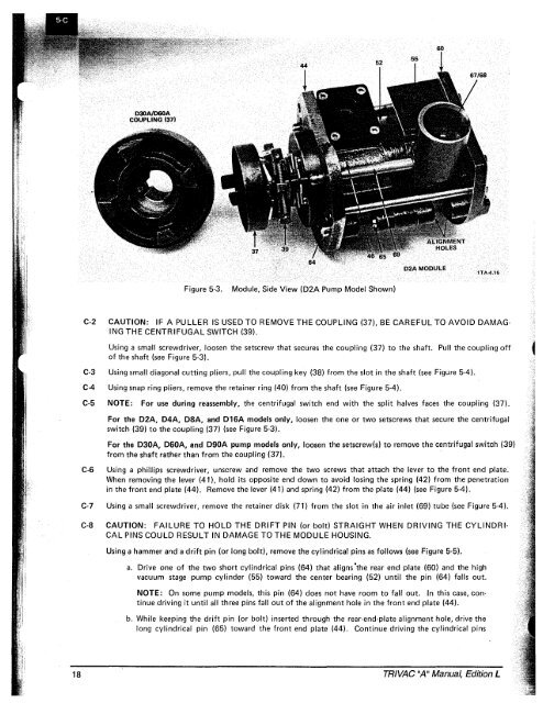
Figure 5-3.<br />
Module, Side View (D2A Pump Model Shown)<br />
C-2 CAUTION: IF A PULLER IS USED TO REMOVE THE COUPLING (37), BE CAREFUL TO AVOID DAMAG<br />
ING THE CENTRIFUGAL SWITCH (39).<br />
Using a small screwdriver, loosen the setscrew that secures the coupling (37) to the shaft. Pull the coupling off<br />
of the shaft (see Figure 5-3).<br />
C-3 Using small diagonal cutting pliers, pull the coupling key (38) from the slot in the shaft (see Figure 5-4).<br />
C-4 Using snap ring pliers, remove the retainer ring (40) from the shaft (see Figure 5-4).<br />
C-5 NOTE: For use during reassembly, the centrifugal switch end with the split halves faces the coupling (37).<br />
For the D2A, D4A, D8A, and D16A models only, loosen the one or two setscrews that secure the centrifugal<br />
switch (39) to the coupling (37) (see Figure 5-3).<br />
For the D30A, D60A, and D90A pump models only, loosen the setscrew(s) to remove the centrifugal switch (39)<br />
from the shaft rather than from the coupling (37).<br />
C-6 Using a phillips screwdriver, unscrew and remove the two screws that attach the lever to the front end plate~<br />
When removing the lever (41), hold its opposite end down to avoid losing the spring (42) from the penetration<br />
in the front end plate (44). Remove the lever (41) and spring (42) from the plate (44) (see Figure 5-4).<br />
C-7 Using a small screwdriver, remove the retainer disk (71) from the slot in the air inlet (69) tube (see Figure 5-4).<br />
C-8 CAUTION: FAILURE TO HOLD THE DRIFT PIN (or bolt) STRAIGHT WHEN DRIVING THE CYLINDRI<br />
CAL PINS COULD RESULT IN DAMAGE TO THE MODULE HOUSING.<br />
Using a hammer and a drift pin (or long bolt). remove the cylindrical pins as follows (see Figure 5-5).<br />
a. Drive one of the two short cylindrical pins (64) that aligns 'the rear end plate (60) and the high<br />
vacuum stage pump cylinder (55) toward the center bearing (52) until the pin (64) falls out.<br />
NOTE: On some pump models, this pin (64) does not have room to fall out. In this case, continue<br />
driving it until all three pins fall out of the alignment hole in the front end plate (44).<br />
b. While keeping the drift pin (or bolt) inserted through the rear-end-plate alignment hole, drive the<br />
long cylindrical pin (65) toward the front end plate (44). Continue driving the cylindrical pins<br />
18<br />
<strong>TRIVAC</strong> "A" Manual, Edition L


