Polarization and Polarization Controllers - NTNU
Polarization and Polarization Controllers - NTNU
Polarization and Polarization Controllers - NTNU

Create successful ePaper yourself
Turn your PDF publications into a flip-book with our unique Google optimized e-Paper software.
5 Applications<br />
Applications of polarization controllers in optical networks range from compensation of polarization<br />
related effects that are detrimental to system performance, to useful exploitation of the polarization<br />
phenomenon. Three cases are presented briefly: polarization optimization, PMD compensation <strong>and</strong><br />
polarization demultiplexing.<br />
All cases involve dynamic (also called automatic) polarization control. Since the SOP changes<br />
r<strong>and</strong>omly with time in installed fiber cables, one needs an automatic control system that monitors the<br />
system <strong>and</strong> continuously adjusts the controllers to ensure that the system performs optimally.<br />
5.1 <strong>Polarization</strong> optimization<br />
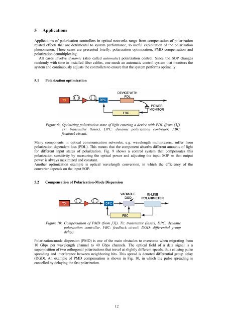
Figure 9: Optimizing polarization state of light entering a device with PDL (from [3]).<br />
Tx: transmitter (laser), DPC: dynamic polarization controller, FBC:<br />
feedback circuit.<br />
Many components in optical communication networks, e.g. wavelength multiplexers, suffer from<br />
polarization dependent loss (PDL). This means that the component absorbs different amounts of light<br />
for different input states of polarization. Fig. 9 shows a control system that compensates this<br />
polarization sensitivity by measuring the optical power <strong>and</strong> adjusting the input SOP so that output<br />
power is always maximized <strong>and</strong> constant.<br />
Another optimization example is optical wavelength conversion, in which the efficiency of the<br />
converter depends on the input SOP.<br />
5.2 Compensation of <strong>Polarization</strong>-Mode Dispersion<br />
Figure 10: Compensation of PMD (from [3]). Tx: transmitter (laser), DPC: dynamic<br />
polarization controller, FBC: feedback circuit, DGD: differential group<br />
delay).<br />
<strong>Polarization</strong>-mode dispersion (PMD) is one of the main obstacles to overcome when migrating from<br />
10 Gbps per wavelength channel to 40 Gbps channels. The optical field of a data signal is a<br />
superposition of two orthogonal polarizations that travel at slightly different speeds, thus causing pulse<br />
spreading <strong>and</strong> interference between neighboring bits. This spread is denoted differential group delay<br />
(DGD). An example of PMD compensation is shown in Fig. 10, in which the pulse spreading is<br />
cancelled by delaying the fast polarization.<br />
12