An Indigenous Device for Water Film Thickness Monitoring
An Indigenous Device for Water Film Thickness Monitoring
An Indigenous Device for Water Film Thickness Monitoring

Create successful ePaper yourself
Turn your PDF publications into a flip-book with our unique Google optimized e-Paper software.
TECHNOLOGY-24<br />
<strong>An</strong> <strong>Indigenous</strong> <strong>Device</strong> <strong>for</strong> <strong>Water</strong> <strong>Film</strong> <strong>Thickness</strong> <strong>Monitoring</strong><br />
EXECUTIVE SUMMARY<br />
In-house developed unique pulsating type position and conductance sensors were integrated <strong>for</strong> development of a device<br />
<strong>for</strong> determination of water film thickness. The device was deployed <strong>for</strong> rapid measurement of variation in film thickness<br />
across falling water layer sliding along a weir crest at different flow rates towards optimisation of conditions <strong>for</strong> avoidance<br />
of flow separation. Measurements were needed in a water simulated facility to test the weir crest design of the thermal<br />
baffle located inside the main reactor vessel of PFBR. Construction and operational details of the horizontally mountable<br />
device <strong>for</strong> this application are described.<br />
OUTLINE<br />
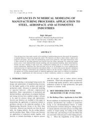
<strong>Film</strong> thicknesses were determined by configuring a<br />
laboratory made pulsating position sensor that enabled<br />
measurement of linear displacement of a horizontally<br />
mounted thin moving rod perpendicular to the vertically<br />
falling water surface. A pair of tiny electrodes as<br />
conductance sensor, mounted aboard the moving rod at<br />
its tip, projecting in the direction of the rod, sensed airwater<br />
interface in front as well as the water-solid surface<br />
interface behind the film. The displacement during<br />
movement of the rod from one interface to the other is the<br />
measure of water film thickness. The device is shown<br />
schematically in Figure 1.<br />
The other end of the rod was fixed to a cylindrical ferrite<br />
core which is partially placed within an inductor coil, and<br />
the linear movement was effected manually by turning<br />
slowly a teflon screw head, the non-threaded end of which<br />
pushed the ferrite core and remained always in contact<br />
with it by action of a spring. The inductor was part of an<br />
oscillator circuit, the output of which was a train of pulses<br />
with frequency at any instant was determined by the<br />
position of the ferrite core and hence that of the tip of the<br />
rod. Shift in pulse frequency was calibrated appropriately<br />
against independently measured displacements prior to<br />
deployment of the device.<br />
The pair of closely placed electrodes <strong>for</strong> conductance<br />
sensing at the tip of the bar was again a part of another<br />
oscillator of different kind, the output pulse frequency of<br />
which was governed by the conductance offered by the<br />
medium that was in contact with the electrodes at a given<br />
moment. Initially, during measurement, as the tip<br />
approaches the water film from air space, the pulse<br />
frequency is nearly zero. Frequency jumps as soon as the<br />
tip touches the air-water interface. The design of the<br />
sensor was such that, thereafter, it increased with<br />
progressive movement towards a value determined by the<br />
conductivity of water. The device had a 0.1 mm thick<br />
stainless steel sheet fixed to the ends of its three legs,<br />
which is pressed firmly against the solid surface, resulting<br />
in the film flowing over the sheet in a small region.<br />
Conductance, and hence the pulse frequency, increased<br />
sharply when, on further advance of the tip, the electrodes<br />
touched the stainless steel surface at the other end of the<br />
film. With no further movement in the <strong>for</strong>ward direction<br />
being possible, the pulse frequencies in both conductance<br />
and position channels attained upper limiting values.<br />
Likewise, during retraction, the air-water interface was<br />
trapped again by sudden fall of pulse frequency to near<br />
zero in the conductance monitoring channel.<br />
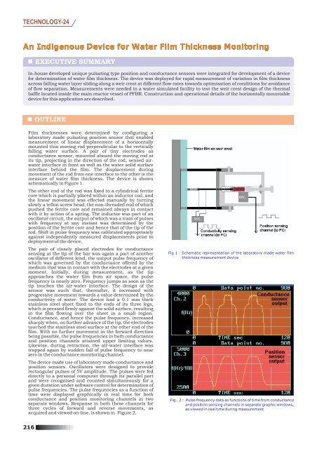
The device made use of laboratory made conductance and<br />
position sensors. Oscillators were designed to provide<br />
rectangular pulses of 5V amplitude. The pulses were fed<br />
directly to a personal computer through its parallel port<br />
and were recognised and counted simultaneously <strong>for</strong> a<br />
given duration under software control <strong>for</strong> determination of<br />
pulse frequencies. The pulse frequencies as a function of<br />
time were displayed graphically in real time <strong>for</strong> both<br />
conductance and position monitoring channels in two<br />
separate windows. Response in both these channels <strong>for</strong><br />
three cycles of <strong>for</strong>ward and reverse movements, as<br />
acquired and viewed on-line, is shown in Figure 2.<br />
Fig 1 : Schematic representation of the laboratory made water film<br />
thickness measurement device<br />
Fig. 2 : Pulse frequency data as functions of time from conductance<br />
and position sensing channels in separate graphic windows,<br />
as viewed in real time during measurement<br />
216
TECHNOLOGY-24<br />
PERFORMANCE OF THE DEVICE<br />
The device was designed <strong>for</strong> measurement of thickness of the film in the range 0 – 10 mm. Inherent standard deviation of<br />
0.3 mm <strong>for</strong> was largely due to small ripples introduced by the hand-held dynamic device in addition to unavoidable factors<br />
such as surface tension that manifests when the conductance sensing electrode tips touch or leave the air-water interface.<br />
EXTRACTION OF WATER FILM THICKNESS DATA<br />
The difference in measured pulse frequencies in position<br />
monitoring channel, between the upper limiting value,<br />
corresponding to the steel-water interface, and that at the<br />
instant of sharp change in conductance as the rod enters or<br />
leaves the air-water interface, provided data on displacement<br />
from one interface to the other and, hence, the film thickness.<br />
<strong>Thickness</strong> data in duplicate was obtained in one cycle of<br />
<strong>for</strong>ward and reverse movement. Three such cycles were<br />
repeated in succession at a given location and flow rate. The<br />
film thickness values are thus average of six data in each case.<br />
The manner by which the change in frequency in the position<br />
sensing channel corresponding to film thickness was derived is<br />
further depicted in the Figure 3 by presenting the data from<br />
both the channels together. Movement of the rod between two<br />
interfaces across the film thickness is derived from the<br />
frequency shift to displacement relationship established prior<br />
to measurement.<br />
The vertical lines correspond to onset or disappearance of<br />
conductance signal. The points of intersections with the<br />
position sensor output plot give the pulse frequencies<br />
corresponding to the position of the tip at air-water interface,<br />
with the mean value depicted by the lower horizontal line. The<br />
frequency shift from the upper horizontal line, the water-solid<br />
surface interface, provides data on displacement of the tip<br />
between the interfaces and, thereby, the film thickness.<br />
Fig. 3 : Time dependent pulse frequency data from position and<br />
conductance monitoring channels during <strong>for</strong>ward and<br />
reverse movements of the rod in three cycles<br />
BASIC APPROACH TO SENSING<br />
Position sensing is realised through partial positioning of a ferrite rod within an inductor coil. The inductor is placed in the<br />
timing circuit of a specially designed miniature R-C-L oscillator with fixed R and C. The digital pulse frequency at the<br />
output changes as the inductance (L) offered by the coil varies sensitively with the movement of ferrite rod. Likewise, an<br />
electrode pair is placed in the timing circuit of an appropriately designed R-C oscillator with fixed C to measure<br />
conductance. The output digital pulse frequency changes as the conductance (1/R) varies. Similarity in approach to the<br />
directly measurable primary signal and absence of any signal conditioning hardware led to development of the compact<br />
device <strong>for</strong> water film thickness monitoring.<br />
ACHIEVEMENT<br />
The device has been used successfully <strong>for</strong> an important application as mentioned above. Designers of the weir crest could<br />
experimentally determine the drag coefficient. The device design is of generic nature and can be adopted <strong>for</strong> thickness<br />
monitoring of any conducting liquid film or solid layer, with much better precision <strong>for</strong> the latter. There is also a definite<br />
scope <strong>for</strong> total automation, if needed.<br />
PUBLICATIONS ARISING OUT OF THIS STUDY AND RELATED WORK<br />
K. Veluswamy, G.R. Ravi Prasan, M.P. Pradeep, P. Sahoo, P. Selvaraj, P. Chellapandi and B. Saha,Design note Report No.<br />
PFBR/31260/DN/1007/Rev.A ( 2004).<br />
Further inquiries:<br />
Shri B. Saha, Innovative Instrumentation Section<br />
Electronics and Instrumentation Group, IGCAR, e-mail: saha@igcar.gov.in<br />
217