Seismic Design of Slopes I - Indian Institute of Technology ...
Seismic Design of Slopes I - Indian Institute of Technology ...
Seismic Design of Slopes I - Indian Institute of Technology ...

You also want an ePaper? Increase the reach of your titles
YUMPU automatically turns print PDFs into web optimized ePapers that Google loves.
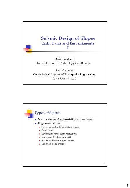
<strong>Seismic</strong> <strong>Design</strong> <strong>of</strong> <strong>Slopes</strong><br />
Earth Dams and Embankments<br />
I<br />
Amit Prashant<br />
<strong>Indian</strong> <strong>Institute</strong> <strong>of</strong> <strong>Technology</strong> Gandhinagar<br />
Short Course on<br />
Geotechnical Aspects <strong>of</strong> Earthquake Engineering<br />
04 – 08 March, 2013<br />
Types <strong>of</strong> <strong>Slopes</strong><br />
• Natural slopes w/o existing slip surfaces<br />
• Engineered slopes<br />
• Highway and railway embankments<br />
• Earth dams<br />
• Levees and River bank protections<br />
• Cut slopes (with natural soil)<br />
• <strong>Slopes</strong> with retaining structures<br />
• Landfills (Solid waste)<br />
2<br />
1
Embankment failure due to liquefaction in<br />
south <strong>of</strong> Lima Peru near the Pacific Ocean<br />
Slope Failures<br />
A Dam Breach – Piping Failure<br />
3<br />
Location: Walla Walla County<br />
Slope Failure!!<br />
Lower San Fernando Dam following the earthquake <strong>of</strong> 1971<br />
(Photos from National Information Service for Earthquake<br />
Engineering, University <strong>of</strong> California, Berkeley)<br />
4<br />
2
Cause <strong>of</strong> Failure<br />
• Major Cause<br />
• Slope failure because <strong>of</strong> inertial loading<br />
• Increase in Shear Stress<br />
• S<strong>of</strong>tening <strong>of</strong> materials strength or liquefaction.<br />
• Decrease in Shear Strength<br />
• Other Causes<br />
• Crest settlement <strong>of</strong> dam caused by settlement or by<br />
earthquake generated water waves in the reservoir.<br />
• Permanent deformation <strong>of</strong> foundation soils or dam body.<br />
• Fault displacement under the foundation.<br />
• Piping and erosion<br />
5<br />
Cause <strong>of</strong> Failure<br />
Increase in Shear Stress<br />
• Erosion / Excavation at the bottom <strong>of</strong> slope<br />
• Sudden drop in water level or drawdown <strong>of</strong> water bodies<br />
• Overloading at the top <strong>of</strong> slope<br />
• Water pressure from crack and fishers<br />
• Freezing <strong>of</strong> water creates even more pressure<br />
• Saturation <strong>of</strong> slopes due to rainfall<br />
• Transitory loading Earthquake loading<br />
6<br />
3
Cause <strong>of</strong> Failure<br />
Decrease in Shear Strength<br />
• Weathering due to physicochemical activities<br />
• Decomposition <strong>of</strong> rocks / boulders due to wetting / drying<br />
process.<br />
• Structural degradation due to cyclic loading<br />
• Traffic, Earthquake loading, Hydrodynamic forces, etc.<br />
• Creep effects under sustained shear loading and seasonal<br />
variations on slopes<br />
• Cracking in cohesive soils<br />
• Change in void ratio in swelling clays<br />
• Decrease in effective stress due to pore pressure build-up<br />
• Earthquake!!<br />
• Effect <strong>of</strong> vibrations on sensitive clays Earthquakes!!<br />
• Erosion <strong>of</strong> dispersive soils (cavity formations) during seepage<br />
• Progressive failure due to strain s<strong>of</strong>tening soil mass<br />
7<br />
Failure Modes in Dams<br />
• Overtopping<br />
• Erosion<br />
• Progressive failure to catastrophe<br />
• Piping<br />
• Uncontrolled Seepage water<br />
• Structural Failure<br />
• Failure <strong>of</strong> upstream/downstream slope<br />
• Cracking, deformation, and settlement<br />
Overtopping / Piping<br />
8<br />
4
Preventive Measures<br />
1. Additional dam height<br />
2. Measures to minimize erosion in the event <strong>of</strong> overtopping.<br />
3. Filter sections as a defense against cracking.<br />
4. Use <strong>of</strong> subrounded gravel/sand as filter material.<br />
5. Near vertical chimney drain in the center portion<br />
6. Zoning <strong>of</strong> the section to minimize saturation <strong>of</strong> materials.<br />
7. Uniformly graded filter materials Self healing if cracking occurs.<br />
8. Safe Rim slopes to avoid large slides into the reservoir.<br />
9. Ground improvement to mitigate liquefaction potential<br />
10. Suitable features to prevent piping.<br />
9<br />
Investigations<br />
• Seismological Investigations<br />
• Past earthquakes probability <strong>of</strong> future earthquakes<br />
• Need long seismic history<br />
• Geotechnical Investigations<br />
• Topographic conditions.<br />
• Description <strong>of</strong> geology.<br />
• Foundation soils, bedrock and soils from borrow area.<br />
• Principal engineering properties: grain characteristics,<br />
plasticity, compaction, shear strength, dispersivity and<br />
hydraulic properties.<br />
• In-situ testing: piezocone penetration test, Standard<br />
Penetration Test or Field Vane Shear Test, seismic velocity<br />
pr<strong>of</strong>iling.<br />
10<br />
5
Liquefaction<br />
• Foundation Soil<br />
• Effective stress may not go to zero, but reduced shear<br />
strength due to low effective stresses can cause large<br />
deformations<br />
• Sensitive clays <strong>of</strong> low to moderate plasticity are problem<br />
• Compaction <strong>of</strong> Embankment<br />
• Compacted enough to make the material dilative<br />
• Compaction density<br />
• > 95% <strong>of</strong> MDD through standard proctor for embankments<br />
• > 98% <strong>of</strong> MDD through standard proctor for dams<br />
• Cohesive soils compacted at moisture content 2-4% higher<br />
than optimum<br />
• In cohesionless soils, 80% relative density is achieved<br />
11<br />
<strong>Seismic</strong> Slope Stability<br />
• Static Slope Stability Analysis First!!<br />
• <strong>Seismic</strong> slope stability analysis<br />
• Pseudo-static analysis<br />
• Assuming equivalent static force for seismic acceleration in<br />
unstable region<br />
• Factor <strong>of</strong> safety estimation<br />
• Permanent deformation analysis<br />
• Based on sliding block concept<br />
• Useful if Pseudo-static analysis does not satisfy required FOS.<br />
• Sophisticated dynamic analysis<br />
• Requires good estimates <strong>of</strong> material properties and input<br />
ground motion.<br />
• Useful if Permanent deformation analysis fails to satisfy<br />
requirements. Needed in big projects<br />
12<br />
6
Static Slope Stability Analysis<br />
• Infinite <strong>Slopes</strong><br />
• Movement predominantly along planar or gently<br />
undulating surfaces over a long stretch<br />
• Land Spreading!!<br />
• Finite <strong>Slopes</strong><br />
• Planer Wedge Method<br />
• Circular Slip surface<br />
• Swedish circle, Friction circle<br />
• Method <strong>of</strong> slices: OMS, Simplified Bishop’s, Bishop’s Rigorous<br />
method<br />
• Non-circular Slip surface<br />
• Log spiral<br />
• Method <strong>of</strong> slices: Simplified Janbu’s, Janbu’s rigorous method,<br />
Generalized Limit Equilibrium method<br />
13<br />
Non-circular Slip Surface<br />
14<br />
7
Conditions for Stability Analysis<br />
• Various Phases <strong>of</strong> Construction<br />
• Short-term stability after construction<br />
• Long-term stability after construction<br />
• Rapid drawdown: dams and Levees<br />
AND THEN…..<br />
• Natural disturbance<br />
• Flooding<br />
• Heavy precipitations<br />
• Accumulation <strong>of</strong> material from up stream<br />
• Earthquakes<br />
15<br />
Total-Stress / Effective-Stress Analysis<br />
Total Stress Analysis<br />
Effective Stress Analysis<br />
<br />
f u = 0, saturated clay<br />
c u<br />
f u ≥ 0<br />
Partially saturated clay<br />
c<br />
tanf<br />
c f<br />
Parameters obtained from:<br />
UC test<br />
UU test<br />
CU test (without pore pressure)<br />
<br />
<br />
f<br />
Parameters obtained from:<br />
Direct Shear<br />
CU test (with pore pressure)<br />
CD test<br />
<br />
Applicable to<br />
• Undrained conditions<br />
• Clays<br />
Applicable to<br />
• Drained/Undrained conditions<br />
• Clays and Sands<br />
16<br />
8
Factor <strong>of</strong> safety<br />
• Along critical slip surface<br />
Resisting force<br />
FOS Driving force<br />
• It does not account for uncertainties involved in determination<br />
<strong>of</strong> soil properties and geometric properties <strong>of</strong> the slope<br />
• More uncertainty Larger FOS<br />
• Higher FOS is taken if slope failure may cause:<br />
• Expensive repair/reconstruction<br />
• Secondary failures to other structures<br />
• Damage to structures <strong>of</strong> high importance<br />
• Usual range <strong>of</strong> FOS for Static analysis = 1.25 – 1.5<br />
17<br />
Back to- <strong>Seismic</strong> Slope Stability<br />
Pseudo-static analysis: Basics<br />
a h (t)<br />
Sliding<br />
Slope<br />
a v (t)<br />
F<br />
h<br />
ahW<br />
<br />
g<br />
k W<br />
h<br />
F<br />
v<br />
avW<br />
<br />
g<br />
k W<br />
v<br />
<strong>Seismic</strong> Coefficient:<br />
k<br />
h <br />
ah<br />
g<br />
k<br />
v <br />
av<br />
g<br />
18<br />
9
Factor <strong>of</strong> Safety and <strong>Seismic</strong> Coefficient<br />
• Complex ground shaking replaced by a single<br />
constant unidirectional pseudo-static acceleration<br />
• Can we consider peak seismic acceleration with<br />
FOS=1? (No deformation…)<br />
• Too conservative<br />
• We can allow some deformation, what should be the seismic<br />
coefficient.<br />
• For sure, some deformation is acceptable….<br />
• A value lower than peak seismic acceleration can be used to<br />
compute seismic coefficient<br />
• FOS can be taken in the range <strong>of</strong> 1.0 - 1.1<br />
• Is there any other factor to consider?<br />
19<br />
Waves travelling through Slope<br />
Kramer, 1996<br />
• Long wavelengths (Low frequency) cause the<br />
unstable zone to move in-phase along the full height.<br />
• Fort short wavelengths (higher frequency) the soil at<br />
two different locations in unstable zone may move in<br />
opposite directions<br />
20<br />
10
Concept <strong>of</strong> Average Acceleration<br />
Kramer, 1996<br />
• We can compute the stresses at different points<br />
throughout the slope for a given seismic input.<br />
• Integrate horizontal components <strong>of</strong> the stresses in the<br />
area above slip surface total horizontal force in<br />
that region.<br />
• Average acceleration = Total horizontal force divided<br />
by mass <strong>of</strong> the zone.<br />
21<br />
Example <strong>of</strong> Average acceleration<br />
22<br />
11
<strong>Seismic</strong> coefficient<br />
• <strong>Seismic</strong> coefficient can be slightly lower than peak<br />
average acceleration (a avg ) max <br />
a avg<br />
0.5<br />
0.8<br />
• From example<br />
a max = 0.60g<br />
(a avg ) max = 0.22g<br />
k h = 0.11g to 0.18g<br />
k<br />
h<br />
<br />
g<br />
max<br />
23<br />
<strong>Seismic</strong> coefficient (contd….)<br />
• Terzaghi (1950)<br />
• 0.1g for severe earthquake (RF Intensity IX)<br />
• 0.2g for violent, destructive earthquake (RF X)<br />
• 0.50g for catastrophic earthquake<br />
• Mercuson (1981)<br />
• <strong>Seismic</strong> coefficient should be one-third to one-half <strong>of</strong> the<br />
PGA the embankment is subjected to<br />
What do you Think?<br />
24<br />
12
<strong>Seismic</strong> coefficient (contd….)<br />
• Hynes and Franklin (1984)<br />
• Embankment with yield acceleration (FOS=1.0) <strong>of</strong><br />
• one-half the PGA will experience permanent deformation <strong>of</strong><br />
less than about 0.1m.<br />
• Deformation limited to 1.0m if yield acceleration is greater than<br />
one-sixth <strong>of</strong> Peak Average Acceleration<br />
• Based on upper bound graph<br />
• See figure for the concept <strong>of</strong> peak average acceleration<br />
25<br />
Permanent <strong>Seismic</strong> Deformation (Hynes and Franklin, 1984)<br />
26<br />
13
<strong>Seismic</strong><br />
coefficients<br />
suggested in<br />
1966 for use in<br />
pseudostatic<br />
analysis<br />
(after Seed 1966)<br />
27<br />
IITK-GSDMA Guidelines for<br />
<strong>Seismic</strong> Coefficient<br />
In the absence <strong>of</strong> site-specific estimates <strong>of</strong> design peak ground, the design<br />
seismic inertia forces for equivalent-static slope stability assessment shall be<br />
taken as:<br />
Where F H is the horizontal inertial force, Z is the Zone Factor given in IS:1893<br />
- Part 1 (2002), I is the importance factor as per Table 1, S is an empirical<br />
coefficient to account for the amplification <strong>of</strong> ground motion between<br />
bedrock and the elevation <strong>of</strong> the toe <strong>of</strong> the dam or embankment (Table 2),<br />
and W is the weight <strong>of</strong> the sliding mass.<br />
If the estimate <strong>of</strong> design peak ground horizontal acceleration (PHGA) at the<br />
elevation <strong>of</strong> the toe <strong>of</strong> the dam is available, the design seismic inertia forces<br />
for equivalent-static slope stability assessment shall be taken as:<br />
where a max is the design PHGA at the elevation <strong>of</strong> the toe <strong>of</strong> the dam.<br />
The vertical inertial force during an earthquake may be neglected in the<br />
design.<br />
28<br />
14
IITK-GSDMA Guidelines for<br />
<strong>Seismic</strong> Coefficient (contd…)<br />
IS:1893<br />
IITK-GSDMA<br />
29<br />
IITK-GSDMA<br />
30<br />
15
31<br />
Thank You<br />
32<br />
16