3D Cranio-Facial Surface Modeling from 2D CT Slices Using ... - ijcee
3D Cranio-Facial Surface Modeling from 2D CT Slices Using ... - ijcee
3D Cranio-Facial Surface Modeling from 2D CT Slices Using ... - ijcee

Create successful ePaper yourself
Turn your PDF publications into a flip-book with our unique Google optimized e-Paper software.
International Journal of Computer and Electrical Engineering, Vol. 2, No. 5, October, 2010<br />
1793-8163<br />
<strong>3D</strong> <strong>Cranio</strong>-<strong>Facial</strong> <strong>Surface</strong> <strong>Modeling</strong> <strong>from</strong> <strong>2D</strong> <strong>CT</strong><br />
<strong>Slices</strong> <strong>Using</strong> Fast Corner Detector<br />
Menaka.R and Chellamuthu. C<br />
<br />
Abstract—This paper presents a novel approach for <strong>3D</strong><br />
<strong>Cranio</strong>-<strong>Facial</strong> reconstruction using Fast Corner detector. The<br />
Method involves Bilateral Filtering as the preprocessing step to<br />
suppress unwanted distortions.The contours representing the<br />
bony areas of the skull are extracted using Region of interest<br />
processing.The feature points required for the point cloud<br />
generation are detected by FAST corner detector. The<br />
generated point cloud is subjected to Delaunay triangulation<br />
for surface reconstruction. The results are compared with three<br />
different <strong>3D</strong> reconstruction methods.<br />
Index Terms—Fast Corner Detector, point cloud, <strong>3D</strong><br />
Reconstruction, Triangulation<br />
I. INTRODU<strong>CT</strong>ION<br />
Retrieving three-dimensional geometric information of<br />
objects <strong>from</strong> two-dimensional images is one of the challenging<br />
tasks in Medical image modeling. Reconstruction of <strong>3D</strong><br />
surface models using <strong>2D</strong> Computed Tomographic slices<br />
provides many advantages to the doctors in diagnosing the<br />
pathological formations and preparing the treatment plans. <strong>3D</strong><br />
<strong>Surface</strong> rendering is used for visualizing the shapes of <strong>3D</strong><br />
objects and the spatial relationships among these objects. The<br />
surfaces of objects are first defined by set of points in <strong>3D</strong> and<br />
modeled by polygons or other geometric primitives through<br />
segmentation or surface detection. These geometrical<br />
primitives are then rendered using the conventional computer<br />
graphics techniques for geometrical objects. The set of points<br />
extracted <strong>from</strong> each <strong>CT</strong> slice is referred to as point cloud where<br />
the terms “feature point” and “corner” refer to a small point of<br />
interest with variation in two dimensions. Such points often<br />
arise as the result of geometric discontinuities, such as the<br />
corners of real world objects, but these may also arise <strong>from</strong><br />
small patches of texture.<br />
There are numerous techniques available for point cloud<br />
generation and surface reconstruction. Some of the corner<br />
point detectors are Harris detector, Susan detector etc.<br />
Harris. C, Stephens .M, [2] suggests that the Harris corner<br />
detector computes a matrix related to the autocorrelation<br />
function of the image and the eigen values of the resulting<br />
matrix are the principal curvatures of the Auto-correlation<br />
function. An interest point is detected if the found two<br />
curvatures are high. The main advantage of Harris operator is<br />
that the detected points are well proportioned and valid. The<br />
disadvantage is the detection accuracy can only reach one<br />
pixel.<br />
Jie Chen, Li-hui Zou [3], describes that Susan corner<br />
detector, places a circular mask over the pixel to be tested (the<br />
nucleus). If the brightness of each pixel within a mask is<br />
compared with the brightness of that mask's nucleus , then an<br />
area of the mask can be defined which has the same (or similar)<br />
brightness as the nucleus. The disadvantage is that a fixed<br />
global threshold is not suitable and the anti-noise ability is<br />
weak.<br />
Some of the surface reconstruction includes trilinear<br />
interpolation, Marching cubes, Delaunay triangulation etc.<br />
William. E Lorensen, Harvey, [8] describes Marching Cubes<br />
technique that creates a triangular mesh to approximate the<br />
iso-surface. Algorithm works by locating the surface in a cube<br />
of eight pixels and calculates normals. I.Fujishiro, Y. Maeda, H.<br />
Sato, et al [6], extracted the tetrahedral meshes between two<br />
isosurfaces <strong>from</strong> volume datasets. Drawback is that holes will<br />
get generated in the model<br />
Fasto Bernardini, Joshua Mittleman, [1] computes a triangle<br />
mesh interpolating a given point cloud. But, it fails to work well<br />
for large quantity of points.<br />
The reconstruction of a surface consistent with the parallel<br />
contours is a very intriguing and challenging problem, as the<br />
construction can be non-unique due to severe topology<br />
variations or sparseness of contours. In this work, FAST<br />
corner detector is used for Point cloud generation due to its<br />
Computational time efficiency. Delaunay triangulation is<br />
employed for surface reconstruction.<br />
II. PROPOSED SYSTEM<br />
A method is proposed using FAST (Features <strong>from</strong><br />
Accelerated Segment Test) Corner Detector to locate the<br />
interest points for point cloud generation. Delaunay<br />
Triangulation is applied to the point cloud for <strong>3D</strong> surface<br />
Reconstruction.<br />
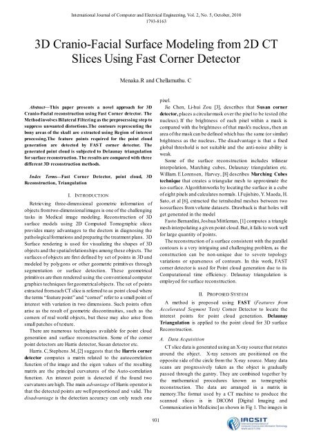
A. Data Acquisition<br />
<strong>CT</strong> slice data is generated using an X-ray source that rotates<br />
around the object. X-ray sensors are positioned on the<br />
opposite side of the circle <strong>from</strong> the X-ray source. Many data<br />
scans are progressively taken as the object is gradually<br />
passed through the gantry. They are combined together by<br />
the mathematical procedures known as tomographic<br />
reconstruction. The data are arranged in a matrix in<br />
memory.The format used by a <strong>CT</strong> machine to produce the<br />
scanned slices is in DICOM [Digital Imaging and<br />
Communication in Medicine] as shown in Fig 1. The images in<br />
931
International Journal of Computer and Electrical Engineering, Vol. 2, No. 5, October, 2010<br />
1793-8163<br />
this format contains information about the slice angle, depth<br />
etc. Normally the thickness of the slice will be .75 mm.<br />
Fig 1. DICOM Image<br />
with a pixel spacing of [2 X 1 double] and with a height and<br />
width of 512 X 512. DICOM format can differentiate up to 1024<br />
gray levels whereas TIFF format can differentiate up to 256<br />
levels proposed system is intended to have low memory<br />
requirements. Hence slices are converted <strong>from</strong> DICOM format<br />
to TIFF format, without losing the structural information.<br />
B. System Description<br />
The functional modules of the system have two phases<br />
namely pre-processing and reconstruction. Pre-processing<br />
involves bilateral filtering and further processing includes<br />
Slice Thresholding, ROI processing, FAST corner detection<br />
and Point cloud generation.<br />
<strong>Surface</strong> reconstruction is performed through Delaunay<br />
triangulation. Fig 2 depicts the System architecture of the<br />
system<br />
C. Pre-processing<br />
Pre-processing is carried out to suppress unwanted<br />
distortions or enhances some image features important for<br />
further processing. Bilateral Filtering is applied to remove<br />
unwanted noise and distortions.<br />
D. Bilateral Filtering:<br />
A bilateral filter is an edge-preserving smoothing filter. It<br />
replaces a pixel's value by a weighted average of its neighbors<br />
in both space and range (pixel value). This preserves sharp<br />
edges by systematically excluding pixels across<br />
discontinuities <strong>from</strong> consideration. For the central pixel of the<br />
neighborhood ao, its new value, denoted by,<br />
Fig 3. Bilateral Filtered Image<br />
where „g‟ is the domain filter and ‘r’ is the range filter, ‘k‟ being<br />
the normalization constant. Bilateral filtered image is shown in<br />
Fig 3.<br />
E. Region of Interest (ROI) Processing<br />
ROI returns a region of interest within an indexed or<br />
intensity image and returns a binary image. Threshold required<br />
for ROI processing is determined by global thresholding of <strong>CT</strong><br />
slice.<br />
Global Threshold:<br />
Global threshold is computed by determining the average<br />
value of the maximum and the minimum pixel value of the <strong>CT</strong><br />
slices. Threshold range used is tabulated in Table 1.<br />
TABLE 1. THRESHOLD RANGE<br />
SLICE NO<br />
THRESHO LD RANGE<br />
1-215 0.4-0.5<br />
216-236 0.3-0.4<br />
ROI processing is carried out for each <strong>CT</strong> slice and the result<br />
of this process is shown in Fig 4.<br />
F. FAST Corner Detection<br />
The feature detector considers pixels in a Bresenham<br />
circle of radius r around the candidate point. If n contiguous<br />
pixels are all brighter than the nucleus by at least threshold<br />
„t‟ or all darker than the nucleus by „t‟, then the pixel under the<br />
nucleus is considered to be a feature.<br />
FAST corner detector operates in two stages. It begins by<br />
using the segment test criterion for „n‟ number of pixels and a<br />
convenient threshold.<br />
... ( 1 )<br />
Fig 4. ROI processed image<br />
Fig 2. System Architecture<br />
932<br />
Let P be the set of all pixels in the test image. P is partitioned<br />
into three subsets Pd (darker), Ps (similar), Pb (Brighter). Every<br />
center pixel is compared with the set of contiguous pixels<br />
around it. If all the contiguous pixels are all either darker or<br />
brighter when compared to the center pixel, then the pixel<br />
under consideration can be defined as a corner point.<br />
FAST Corner Detector is computationally efficient and<br />
provides stable features. It has high detection rate and the
International Journal of Computer and Electrical Engineering, Vol. 2, No. 5, October, 2010<br />
1793-8163<br />
factor of repeatability proves to be good for affine<br />
transformations.FAST corner detector is applied to the ROI<br />
detected image to locate the interest points and the result is<br />
shown in Fig 5.<br />
G. Point Cloud Generation:<br />
Point cloud represents visible surfaces of an object. point<br />
cloud is generated by processing all the <strong>2D</strong> images required to<br />
reconstruct the three dimensional structure. To obtain the<br />
point cloud, metadata contained in the header of each<br />
individual slice is collected .The contoured slices are<br />
processed to obtain the three dimensional coordinate vertices<br />
of the points. The coordinate positions of the pixels are taken<br />
with respect to a reference point for each slice. These three<br />
dimensional vertices represents the point cloud. The following<br />
equations are used for finding the vertices<br />
X new = x (i,j)* pixelspace + offsetx (2)<br />
Y new = y (i,j)* pixelspace + offset y (3)<br />
Z k = z k-1 - Gap (K=2….No of slices) (4)<br />
Z 1 = Offset z (5)<br />
Offset x - reference point (origin) in the<br />
X direction<br />
Offset y - reference point (origin) in the<br />
Y direction<br />
Offset z - reference point in the (origin)<br />
in the Z direction.<br />
Gap - the distance between the adjacent slices.<br />
i, j – coordinates in X ,Y direction.<br />
The point cloud for the <strong>CT</strong> slices is shown in Fig 6.<br />
A Delaunay triangulation for a set P of points in the plane is<br />
a triangulation DT (P) such that no point in P is inside the<br />
circumcircle of any triangle in DT (P) as shown in Fig 7.<br />
It maximizes the minimum angle of all the angles of the<br />
triangles in the triangulation. They tend to avoid skinny<br />
triangles.<br />
Delaunay triangulation is applied to the co-ordinates<br />
obtained <strong>from</strong> the point cloud. The resultant output of this<br />
process is shown in Fig 8.<br />
III. RESULTS AND DISCUSSION<br />
A set of 236 <strong>CT</strong> slices in axial plane has been collected <strong>from</strong><br />
a male patient. It is subjected to both preprocessing and<br />
reconstruction phases. The final <strong>3D</strong> reconstructed structure is<br />
shown in Fig 9.<br />
The final reconstructed structure obtained by various<br />
methods is compared in Fig. 10, 11 and 12. The time taken for<br />
reconstruction using FMWP (FAST method without<br />
preprocessing) and FMP (FAST method with preprocessing)<br />
is found to be comparable with the Marching Cubes method<br />
(MCR), Sobel detector based reconstruction (SBR) and Harris<br />
detector based reconstruction.(HBR<br />
Fig 7. Circumcircle property<br />
Fig 5. FAST Corner Detection<br />
Fig 8. Delaunay Triangulation<br />
H. Reconstruction:<br />
Fig 6. Generated Point cloud<br />
Reconstruction is performed to obtain the <strong>3D</strong> structure.<br />
Delaunay Triangulation is used in the reconstruction process .<br />
Delaunay Triangulation<br />
Fig 9. <strong>3D</strong> Reconstructed Skull<br />
Chart 1. Comparison of Reconstruction time<br />
933
Method<br />
International Journal of Computer and Electrical Engineering, Vol. 2, No. 5, October, 2010<br />
1793-8163<br />
FMP<br />
HBR<br />
SBR<br />
0 200 400 600<br />
Reconstruction time<br />
(Sec)<br />
TABLE 2. COMPARISON OF T RIANGULAR INDICES<br />
No. of Triangular<br />
Method<br />
Indices<br />
Sobel detector based <strong>3D</strong><br />
reconstruction 30,784<br />
Harris Detector based <strong>3D</strong><br />
Reconstruction ( without<br />
Preprocessing )<br />
FAST Detector based <strong>3D</strong><br />
Reconstruction ( without<br />
Preprocessing )<br />
Fast Detector based <strong>3D</strong><br />
Reconstruction (with Bilateral<br />
Filtering )<br />
8,522<br />
10,348<br />
9,617<br />
Fig 10. Final reconstructed structure by Sobel operator based Method.<br />
Fig 11. Final reconstructed structure by Harris detector Method.<br />
feature point detection and point cloud generation and the <strong>3D</strong><br />
reconstructed structure of the skull is visualized. It has been<br />
observed that the reconstruction time is reduced by 40% when<br />
compared to sobel detector based reconstruction. Also the<br />
number of triangular indices formed is reduced by 30%.<br />
Reconstruction time is much reduced due to high detection<br />
rate of FAST corner detector. FAST corner detector is applied<br />
to medical images for the first time. The work of this paper<br />
provides a new direction in the improvement of point cloud<br />
generation.<br />
ACKNOWLEDGEMENT<br />
The authors wish to thank RAGAS DENTAL COLLEGE,<br />
CHENNAI for providing the <strong>CT</strong> <strong>Slices</strong> and Dr. Gnanasundaram<br />
Professor Dept of Oral Medicine, SAVEETHA DENTAL<br />
COLLEGE for his several key suggestions in improving this<br />
paper.<br />
REFERENCES<br />
[1] Fausto Bernardini, Joshua Mittleman Holly Rushmeier Cl áudio<br />
Silva Gabriel Taubin. “The Ball Pivoting Algorithm for surface<br />
reconstruction”, IEEE Transactions on Visualization and<br />
Computer Graphics, 5(4), Oct-Dec, 1999, pp. 349-359.<br />
[2] Harris, C., Stephens, M, “ A combined corner and edge detector”.<br />
In: Fourth Alvey Vision Conference, Manchester, UK, pp.147-151,<br />
1988.<br />
[3] Jie Chen, Li-hui Zou, Juan Zhang and Li-hua Dou., “The<br />
Comparison and Application of Corner Detection<br />
Algorithms” ,Journal of Multimedia, Vol. 4, no. 6, December 2009.<br />
[4] E. Rosten and T. Drummond ,”Machine learning for high-speed<br />
corner detection”, ECCV 2006.<br />
[5] Sander Koelstra, Ioannis Patras, "The fast-<strong>3D</strong> spatio-temporal<br />
interest region detector”, 10th Workshop on Image Analysis for<br />
Multimedia Interactive Services 2009.<br />
[6] .Fujishiro, Y. Maeda, H. Sato, et al., “Volumetric data exploration<br />
using interval volume”,IEEE Tran. Visualization and Computer<br />
Graphics, 1996, Vol. 2, pp. 144-155.<br />
[7] Wenlian Cheng, Zhiya Qian, Lina Lu,”Research On Medical Image<br />
Three Dimensional Visualization System”.<br />
[8] William E. Lorensen, Harvey E.Cline “ Marching Cubes: A High<br />
Resolution <strong>3D</strong> <strong>Surface</strong> Construction Algorithm”, – SIG ‟87<br />
IEEE/ICME International Conference on Complex Medical<br />
Engineering, 2007.<br />
[9] Wu Z, Sullivan JM., “ Multiple material marching cubes<br />
algorithm”, International Journal for Numerical Methods in<br />
Engineering 2003; 58(2):189 –2007.<br />
Mrs R Menaka , received the master degree in Engineering in Applied<br />
Electronics <strong>from</strong> Anna University, Chennai., India. Bachelor of<br />
Engineering in Electronics and Communication Engineering <strong>from</strong><br />
Madurai Kamaraj University, India. Currently she is currently working<br />
as Associate Professor in School of electronics , VIT University,<br />
Chennai. and also a research Scholar in Anna University, Chennai, India.<br />
Her areas interest are Image processing, Neural Networks and fuzzy<br />
logic.<br />
Dr C Chellamuthu received his PhD degree in Power Electronics<br />
<strong>from</strong> IIT, Chennai, India. After working as Associate lecturer in G<strong>CT</strong>,<br />
Coimbatore, India, he joined Anna University, Chennai, India.as<br />
Lecturer. He served there as Asst professor ,professor and as Head of<br />
Department of Electrical and Electronics Engineering. He is currently<br />
Fig 12. Final reconstructed structure by FAST detector method. working as professor at RMK College of Engineering, Chennai, India.<br />
He has published his works in Several International and National journals,<br />
pioneered several new research directions, made a number of landmark<br />
contribution in his field. His areas of interest are power<br />
IV. CONCLUSION AND FUTURE WORK<br />
Electronics .PMBDLC designs, Wind Energy, Microprocessor based<br />
FAST Corner detector was applied on each <strong>CT</strong> slice for system design, Image and Video processing and controller area networks.<br />
934