A Low Power, Fully Differential Bulk Driven OTA in 180 nm ... - ijcee
A Low Power, Fully Differential Bulk Driven OTA in 180 nm ... - ijcee
A Low Power, Fully Differential Bulk Driven OTA in 180 nm ... - ijcee

Create successful ePaper yourself
Turn your PDF publications into a flip-book with our unique Google optimized e-Paper software.
International Journal of Computer and Electrical Eng<strong>in</strong>eer<strong>in</strong>g, Vol. 4, No. 3, June 2012<br />
A <strong>Low</strong> <strong>Power</strong>, <strong>Fully</strong> <strong>Differential</strong> <strong>Bulk</strong> <strong>Driven</strong> <strong>OTA</strong> <strong>in</strong> <strong>180</strong><br />
<strong>nm</strong> CMOS Technology<br />
Rekha S. and Laxm<strong>in</strong>idhi T.<br />
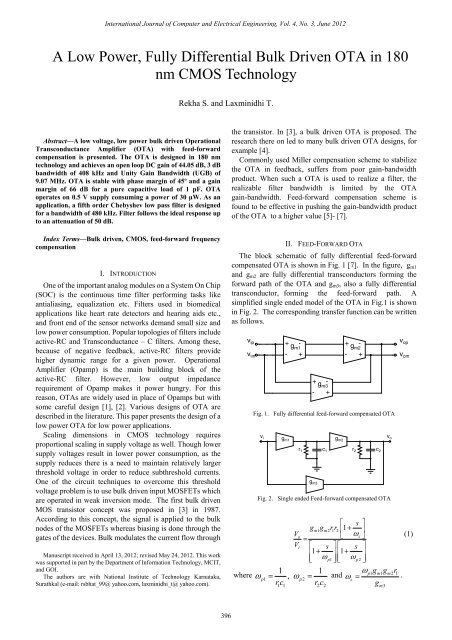
Abstract—A low voltage, low power bulk driven Operational<br />
Transconductance Amplifier (<strong>OTA</strong>) with feed-forward<br />
compensation is presented. The <strong>OTA</strong> is designed <strong>in</strong> <strong>180</strong> <strong>nm</strong><br />
technology and achieves an open loop DC ga<strong>in</strong> of 44.05 dB, 3 dB<br />
bandwidth of 408 kHz and Unity Ga<strong>in</strong> Bandwidth (UGB) of<br />
9.07 MHz. <strong>OTA</strong> is stable with phase marg<strong>in</strong> of 45º and a ga<strong>in</strong><br />
marg<strong>in</strong> of 66 dB for a pure capacitive load of 1 pF. <strong>OTA</strong><br />
operates on 0.5 V supply consum<strong>in</strong>g a power of 30 µW. As an<br />
application, a fifth order Chebyshev low pass filter is designed<br />
for a bandwidth of 480 kHz. Filter follows the ideal response up<br />
to an attenuation of 50 dB.<br />
Index Terms—<strong>Bulk</strong> driven, CMOS, feed-forward frequency<br />
compensation<br />
I. INTRODUCTION<br />
One of the important analog modules on a System On Chip<br />
(SOC) is the cont<strong>in</strong>uous time filter perform<strong>in</strong>g tasks like<br />
antialias<strong>in</strong>g, equalization etc. Filters used <strong>in</strong> biomedical<br />
applications like heart rate detectors and hear<strong>in</strong>g aids etc.,<br />
and front end of the sensor networks demand small size and<br />
low power consumption. Popular topologies of filters <strong>in</strong>clude<br />
active-RC and Transconductance – C filters. Among these,<br />
because of negative feedback, active-RC filters provide<br />
higher dynamic range for a given power. Operational<br />
Amplifier (Opamp) is the ma<strong>in</strong> build<strong>in</strong>g block of the<br />
active-RC filter. However, low output impedance<br />
requirement of Opamp makes it power hungry. For this<br />
reason, <strong>OTA</strong>s are widely used <strong>in</strong> place of Opamps but with<br />
some careful design [1], [2]. Various designs of <strong>OTA</strong> are<br />
described <strong>in</strong> the literature. This paper presents the design of a<br />
low power <strong>OTA</strong> for low power applications.<br />
Scal<strong>in</strong>g dimensions <strong>in</strong> CMOS technology requires<br />
proportional scal<strong>in</strong>g <strong>in</strong> supply voltage as well. Though lower<br />
supply voltages result <strong>in</strong> lower power consumption, as the<br />
supply reduces there is a need to ma<strong>in</strong>ta<strong>in</strong> relatively larger<br />
threshold voltage <strong>in</strong> order to reduce subthreshold currents.<br />
One of the circuit techniques to overcome this threshold<br />
voltage problem is to use bulk driven <strong>in</strong>put MOSFETs which<br />
are operated <strong>in</strong> weak <strong>in</strong>version mode. The first bulk driven<br />
MOS transistor concept was proposed <strong>in</strong> [3] <strong>in</strong> 1987.<br />
Accord<strong>in</strong>g to this concept, the signal is applied to the bulk<br />
nodes of the MOSFETs whereas bias<strong>in</strong>g is done through the<br />
gates of the devices. <strong>Bulk</strong> modulates the current flow through<br />
Manuscript received <strong>in</strong> April 13, 2012; revised May 24, 2012. This work<br />
was supported <strong>in</strong> part by the Department of Information Technology, MCIT,<br />
and GOI.<br />
The authors are with National Institute of Technology Karnataka,<br />
Surathkal (e-mail: rsbhat_99@ yahoo.com, laxm<strong>in</strong>idhi_t@ yahoo.com).<br />
the transistor. In [3], a bulk driven <strong>OTA</strong> is proposed. The<br />
research there on led to many bulk driven <strong>OTA</strong> designs, for<br />
example [4].<br />
Commonly used Miller compensation scheme to stabilize<br />
the <strong>OTA</strong> <strong>in</strong> feedback, suffers from poor ga<strong>in</strong>-bandwidth<br />
product. When such a <strong>OTA</strong> is used to realize a filter, the<br />
realizable filter bandwidth is limited by the <strong>OTA</strong><br />
ga<strong>in</strong>-bandwidth. Feed-forward compensation scheme is<br />
found to be effective <strong>in</strong> push<strong>in</strong>g the ga<strong>in</strong>-bandwidth product<br />
of the <strong>OTA</strong> to a higher value [5]- [7].<br />
II. FEED-FORWARD <strong>OTA</strong><br />
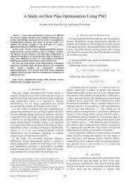
The block schematic of fully differential feed-forward<br />
compensated <strong>OTA</strong> is shown <strong>in</strong> Fig. 1 [7]. In the figure, g m1<br />
and g m2 are fully differential transconductors form<strong>in</strong>g the<br />
forward path of the <strong>OTA</strong> and g m3 , also a fully differential<br />
transconductor, form<strong>in</strong>g the feed-forward path. A<br />
simplified s<strong>in</strong>gle ended model of the <strong>OTA</strong> <strong>in</strong> Fig.1 is shown<br />
<strong>in</strong> Fig. 2. The correspond<strong>in</strong>g transfer function can be written<br />
as follows.<br />
v ip<br />
v im<br />
+<br />
g<br />
- + -<br />
m1<br />
g m2<br />
- + - +<br />
+<br />
-<br />
g m3<br />
Fig. 1. <strong>Fully</strong> differential feed-forward compensated <strong>OTA</strong><br />
v i<br />
where ω<br />
-<br />
+<br />
g m1 g m2<br />
r 1 c 1 r 2 c 2<br />
g m3<br />
Fig. 2. S<strong>in</strong>gle ended Feed-forward compensated <strong>OTA</strong><br />
v o<br />
v op<br />
v om<br />
⎡ s ⎤<br />
gm<br />
1gm2rr<br />
1 2 ⎢1<br />
+<br />
V<br />
ω<br />
⎥<br />
o<br />
⎣ z ⎦<br />
(1)<br />
=<br />
Vi<br />
⎡ s ⎤⎡ s ⎤<br />
⎢1+ ⎥⎢1+<br />
⎥<br />
⎢⎣ ωp<br />
1⎥⎢ ⎦⎣ ωp2⎥⎦<br />
1 1 ωp 1gm1gm2r1<br />
= , ωp<br />
= and ω<br />
z<br />
= .<br />
rc rc<br />
g<br />
p1 2<br />
1 1 2 2<br />
m3<br />
396
International Journal of Computer and Electrical Eng<strong>in</strong>eer<strong>in</strong>g, Vol. 4, No. 3, June 2012<br />
The feed-forward path thus <strong>in</strong>troduces a left half s-plane<br />
zero at s = - ω z which improves the phase marg<strong>in</strong> of the <strong>OTA</strong><br />
without compromis<strong>in</strong>g the band width.<br />
III. FULLY DIFFERENTIAL BULK DRIVEN TRAN CONDUCTOR<br />
It is a common practice to use source coupled differential<br />
pair to realize the transconductor. But due to the limitations<br />
on overhead when operat<strong>in</strong>g with low supply voltages, it is<br />
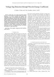
common to use a pseudo differential architecture. A pseudo<br />
differential transconductor is shown <strong>in</strong> Fig. 3. In the figure,<br />
vip and vim are the differential <strong>in</strong>puts and vop and vom are<br />
the differential outputs. M1 and M2 are the <strong>in</strong>put transistors<br />
operat<strong>in</strong>g <strong>in</strong> saturation. M3 and M4 form the NMOS loads<br />
and operate <strong>in</strong> weak <strong>in</strong>version.<br />
V DD<br />
transfer function can be written as <strong>in</strong> (2).<br />
( c c )<br />
2 ⎡ sc ⎤⎡ 1<br />
+ ⎤<br />
1 2 ⎢1<br />
−<br />
c<br />
c<br />
s<br />
g<br />
mb<br />
r r ⎥⎢1<br />
+ ⎥<br />
V<br />
=<br />
⎣ g ⎦⎣<br />
g<br />
o mb<br />
mb ⎦ (2)<br />
2<br />
V<br />
As + Bs + 1<br />
i<br />
V DD<br />
M 1 M 2<br />
v im<br />
v om<br />
v op<br />
v ip<br />
M 1d M 2d<br />
M 3 M 4<br />
M 5<br />
i dc<br />
v cm<br />
v cmfb<br />
v ip<br />
v om<br />
M 1 M 2<br />
v im<br />
v op<br />
v cm<br />
M 3 M 4<br />
M 5<br />
i dc<br />
v cmfb<br />
Fig. 3. Pseudo differential bulk driven transconductor<br />
v ip<br />
c c<br />
-g mb<br />
v om<br />
R <strong>in</strong> C <strong>in</strong> R out C out<br />
Fig. 4. S<strong>in</strong>gle ended small signal model of the transconductor<br />
A s<strong>in</strong>gle ended small signal equivalent circuit of the<br />
differential transconductor is shown <strong>in</strong> Fig. 4. In the figure,<br />
g mb is the transconductance of bulk driven transistor (M 1 /<br />
M 2 ). C <strong>in</strong> and C out are the effective capacitances at <strong>in</strong>put and<br />
output respectively. Similarly, R <strong>in</strong> and R out are the effective<br />
<strong>in</strong>put and output resistances respectively. C c is the effective<br />
coupl<strong>in</strong>g capacitance between the <strong>in</strong>put and the output (bulk<br />
and the dra<strong>in</strong>). This coupl<strong>in</strong>g capacitance can not be ignored<br />
as it is the dra<strong>in</strong> junction capacitance and it <strong>in</strong>troduces a right<br />
half plane zero. A simple scheme to compensate for this<br />
effect is shown <strong>in</strong> Fig. 5. It is to be noted that this will only<br />
compensate for the capacitance but will not cancel the<br />
capacitance altogether.<br />
IV. BULK DRIVEN FEED-FORWARD <strong>OTA</strong><br />
<strong>Bulk</strong> driven feed-forward <strong>OTA</strong> shown <strong>in</strong> Fig. 1 is realized<br />
us<strong>in</strong>g the differential transconductor shown <strong>in</strong> Fig. 5. S<strong>in</strong>gle<br />
ended small signal equivalent circuit of the differential<br />
feed-forward <strong>OTA</strong> is shown <strong>in</strong> Fig. 6 and the correspond<strong>in</strong>g<br />
where<br />
Fig. 5. <strong>Fully</strong> differential <strong>Bulk</strong> driven Transconductor<br />
A = r<br />
1<br />
1<br />
2<br />
( c c + 2c<br />
c + 2c<br />
c + 3c<br />
)<br />
1<br />
r2<br />
1 2 c 1 c 2 c<br />
,<br />
B = r c + r c<br />
2<br />
2<br />
+ g<br />
r r c<br />
mb 1 2<br />
And r1, c 1 and r 2 , c 2 represent the effective impedance seen<br />
at the <strong>in</strong>termediate node of the forward path and output<br />
respectively with respect to small signal ground. In (2), it can<br />
be seen that there are two zeros, one on the left half of s-plane<br />
− gmb<br />
(at )and the other on the right half of s-plane (at<br />
c + c<br />
g<br />
c<br />
mb<br />
c<br />
1<br />
c<br />
). While the left half plane zero is <strong>in</strong>troduced by the<br />
feed-forward transconductor to compensate the <strong>OTA</strong>, the<br />
right half plane zero is <strong>in</strong>troduced due to the coupl<strong>in</strong>g<br />
capacitance, c c . Note that the transistors M 1d and M 2d <strong>in</strong> Fig.<br />
5 attempt to reduce c c to a m<strong>in</strong>imum so that the effect of right<br />
half plane zero is m<strong>in</strong>imized.<br />
c c c c<br />
v i -g mb -g v o<br />
mb<br />
c 1 r c r 2 2<br />
1<br />
c c<br />
-v i -g mb<br />
Fig. 6. Small signal model of feed-forward <strong>OTA</strong><br />
V. SIMULATION RESULTS<br />
A bulk driven differential transconductor is designed <strong>in</strong><br />
<strong>180</strong> <strong>nm</strong> technology to operate at 0.5 V supply. The <strong>in</strong>put and<br />
output common mode voltages of the transconductor are<br />
fixed at 0.25 V. In Fig. 5, gates of M 1 and M 2 are biased to<br />
carry a quiescent current of 10 µA and are sized for a bulk<br />
transconductance of 45 µS. Gates of M 3 and M 4 are biased<br />
2<br />
397
International Journal of Computer and Electrical Eng<strong>in</strong>eer<strong>in</strong>g, Vol. 4, No. 3, June 2012<br />
with a common mode feedback voltage which sets the output<br />
common mode voltage. Transconductor is modeled and<br />
modeled values are as follows.<br />
R <strong>in</strong><br />
R out<br />
C <strong>in</strong><br />
= 14.36 MΩ<br />
= 385.8 kΩ<br />
= 443.577 fF<br />
C out = 189.632 fF<br />
C c = 0.68248 fF<br />
After compensation. It is worth not<strong>in</strong>g that, without the<br />
compensation, C c was 47 fF. Fig. 7 compares the frequency<br />
response of the transistor level transconductor and that of its<br />
model.<br />
Fig. 7. Frequency response of Transistor level differential Transconductor<br />
and of its model<br />
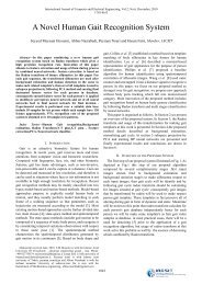
A bulk driven feed-forward compensated <strong>OTA</strong> then built<br />
us<strong>in</strong>g the transconductors. Fig. 8 compares the frequency<br />
response of the transistor level differential <strong>OTA</strong> and of its<br />
model (Fig. 4). <strong>OTA</strong> has an open loop DC ga<strong>in</strong> of 44 dB.<br />
Under no load condition the <strong>OTA</strong> has a 3 dB bandwidth of<br />
601 kHz, UGB of 22 MHz, phase marg<strong>in</strong> of 68.5º and a ga<strong>in</strong><br />
marg<strong>in</strong> of 54.89 dB. It is to be noted that, if it were a Miller<br />
compensation, for the same UGB of 22 MHz, the 3-dB<br />
bandwidth would have been 138 kHz. For a pure capacitive<br />
load of 1 pF, <strong>OTA</strong> has 3 dB bandwidth of 408 kHz, UGB of<br />
9.07 MHz, a phase marg<strong>in</strong> of 45º and a ga<strong>in</strong> marg<strong>in</strong> of 66 dB.<br />
If resistive loads are considered, the phase marg<strong>in</strong> is sure to<br />
be improved as the damp<strong>in</strong>g <strong>in</strong>creases. Table I lists the<br />
parameters of the <strong>OTA</strong>. A comparison of performance<br />
parameters of the designed <strong>OTA</strong> with other low voltage<br />
<strong>OTA</strong>s found <strong>in</strong> the literature is listed <strong>in</strong> Table II.<br />
TABLE I: PARAMETERS OF <strong>OTA</strong><br />
Parameter<br />
Simulate<br />
d values<br />
of <strong>OTA</strong><br />
Supply [V] 0.5<br />
Open loop DC ga<strong>in</strong> [dB] 44<br />
No load 601<br />
3 dB bandwidth [kHz] I pF capacitive load 408<br />
No load 22<br />
UGB [MHz]<br />
I pF capacitive load 9.07<br />
No load 68.5<br />
Phase marg<strong>in</strong><br />
I pF capacitive load 45<br />
[degree]<br />
No load 54.89<br />
Ga<strong>in</strong> marg<strong>in</strong> [dB] I pF capacitive load 66<br />
<strong>Power</strong> [μW] 30 *<br />
Technology [μm] 0.18<br />
Input referred<br />
noise [nV/√Hz]<br />
* exclud<strong>in</strong>g CMFB circuit<br />
@10 kHz 95.8<br />
@1 MHz 65.72<br />
Fig. 8. Frequency response of feed-forward <strong>OTA</strong><br />
TABLE II: COMPARISON WITH OTHER LOW VOLTAGE <strong>OTA</strong> DESIGNS<br />
Parameter [4] [8] [9] [10] [11] [12]<br />
Present<br />
work<br />
Supply (V) 0.5 1 1 0.8 0.9 1.3 0.5<br />
DC ga<strong>in</strong><br />
(dB)<br />
52 70 49 53 70 84 44<br />
UGB<br />
(MHz)<br />
2.5 0.2 1.3 1.3<br />
0.00<br />
6<br />
1.3 9.07<br />
<strong>Power</strong> (μW) 110 5 300 -- 0.5 460 30 *<br />
Technology<br />
(μm)<br />
0.18 0.35 2 0.5 2.5 0.7 0.18<br />
C L (pF) 20 7 22 20 12 -- 1<br />
Input<br />
referred<br />
noise @ 10 220 260 181 -- -- -- 95.8<br />
kHz<br />
[nV/√Hz]<br />
Input<br />
referred<br />
noise @ 1<br />
MHz<br />
[nV/√Hz]<br />
90 -- 43.6 -- -- -- 65.72<br />
* exclud<strong>in</strong>g CMFB circuit<br />
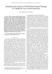
To demonstrate the application of the designed <strong>OTA</strong>, a<br />
fifth order Chebyshev low pass filter is designed and the<br />
schematic of the filter is shown <strong>in</strong> Fig. 9. The filter has a<br />
bandwidth of 480 kHz and a pass band ripple of 1 dB. It is<br />
derived from the ladder architecture [6].<br />
V ip<br />
V im<br />
R<br />
R<br />
R<br />
2<br />
R<br />
2<br />
C 2<br />
C 3<br />
C 4<br />
C 5<br />
R<br />
R<br />
R<br />
R z C 1<br />
R z<br />
R z<br />
R z<br />
R z<br />
-<br />
+<br />
+<br />
-<br />
+<br />
-<br />
-<br />
+<br />
- +<br />
R<br />
R<br />
R<br />
R z C R 1 z C R z<br />
R 2<br />
2 C 3 z C 4 R z<br />
C 5<br />
R<br />
R<br />
2<br />
R<br />
2<br />
+<br />
- -<br />
+<br />
+<br />
-<br />
- + + -<br />
R<br />
R<br />
R<br />
R<br />
R<br />
2<br />
2<br />
Fig. 9. Schematic of fifth order chebyshev filter.<br />
Fig. 10 shows the magnitude response of the transistor<br />
level filter. It can be seen that the response closely matches<br />
with the ideal response up to 1 MHz where the attenuation of<br />
the filter is about 50 dB. The deviation beyond 1 MHz is<br />
attributed to parasitic poles/zeros.<br />
VI. CONCLUSIONS<br />
A fully differential low power <strong>OTA</strong> is described. The <strong>OTA</strong><br />
designed is <strong>in</strong> <strong>180</strong> <strong>nm</strong> CMOS technology and is feed-forward<br />
compensated. It has 44 dB DC ga<strong>in</strong>, 9.07 MHz UGB, 45º<br />
phase marg<strong>in</strong> and 66 dB ga<strong>in</strong> marg<strong>in</strong> at 1 pF pure capacitive<br />
V op<br />
V om<br />
398
International Journal of Computer and Electrical Eng<strong>in</strong>eer<strong>in</strong>g, Vol. 4, No. 3, June 2012<br />
load consum<strong>in</strong>g a power of 30µW from 0.5 V supply. A fifth<br />
order Chebyshev low pass active – RC filter with the cutoff<br />
frequency of 480 kHz is designed as an application of the<br />
<strong>OTA</strong>. Filter response closely matches with the ideal response<br />
up to 1 MHz where the attenuation of the filter is 50 dB.<br />
Fig. 10. Magnitude response of fifth order chebyshev filter<br />
REFERENCES<br />
[1] C. F. Wheatley and H. A. Wittl<strong>in</strong>ge, “<strong>OTA</strong> obsoletes OPAMP," <strong>in</strong><br />
Proc. of National Econ. Conference I, pp.152-157, 1969.<br />
[2] Y. P. Tsividis, “Integrated Cont<strong>in</strong>uous time filters design – An<br />
Overview,” IEEE Journal of solid state circuits, vol. 29, no. 3, pp.<br />
166-176, March 1994.<br />
[3] A .Guz<strong>in</strong>ski, M. Bialko, and J. C. Matheau, “Body driven differential<br />
amplifier for applications <strong>in</strong> cont<strong>in</strong>uous time active-C filter," <strong>in</strong> Proc.<br />
European Conf. Circuit Theory and Design (ECCTD'87), pp. 315-320,<br />
1987.<br />
[4] S. Chatterjee, Y. Tsividis, and P. K<strong>in</strong>get, “0.5V Analog Circuit<br />
Techniques and their Application <strong>in</strong> <strong>OTA</strong> and filter design," IEEE<br />
Journal of Solid-state Circuits, vol. 40, no. 12, pp. 2373-2387, 2005.<br />
[5] J. N. Harrison and N. Weste, “350 MHz Opamp-RC filter <strong>in</strong> 0.18 µm<br />
CMOS,” IEE Electronics Letters, pp.259-260, 2002.<br />
[6] T. Laxm<strong>in</strong>idhi, V. Prasadu and S. Pavan, “Widely programmable high<br />
frequency active RC filters <strong>in</strong> CMOS technology,” IEEE transactions<br />
on circuits & Systems, vol.56, no. 2, pp.327-336, February 2009.<br />
[7] B. Thandri and J. S. Mart<strong>in</strong>ez, “A Robust feedforward compensation<br />
scheme for multistage operational Transconductance Amplifiers with<br />
no miller capacitors,” IEEE J. Solid State Circuits, vol. 38, no.2, pp.<br />
237- 243, Feb. 2003<br />
[8] K. Lasanen, E. R. Ruotsala<strong>in</strong>en, and J. Kostamovaara, “A 1- V 5μW<br />
CMOS-Opamp with <strong>Bulk</strong>-<strong>Driven</strong> Input Transistors," <strong>in</strong> Proc. 43rd<br />
IEEE Midwest Symp. on Circuits and Systems, pp. 1038-1041, pp. 8-11,<br />
2000<br />
[9] B. Blalock, P. Allen, and G.R<strong>in</strong>con-Mora, “Design<strong>in</strong>g 1-V op-amps<br />
us<strong>in</strong>g standard digital CMOS technology," IEEE Trans. Circuits<br />
Systems II, Analog Digital Signal Process, vol. 45, no. 7, pp. 769-780,<br />
1998.<br />
[10] T. Lehmann and M. Cassia, “1-V power supply CMOS cascode<br />
amplifier", IEEE J. Solid State Circuits, vol. 36, no. 7, pp.<br />
1082-1086, July 2001.<br />
[11] T. Stockstad and H. Yoshizawa, “A 0.9V- 0.5μA rail-to-rail CMOS<br />
operational amplifier," IEEE J. Solid State Circuits, vol. 37, pp.<br />
286-292, 2002.<br />
[12] G. Ferri and W. Sansen, “A 1.3V opamp <strong>in</strong> standard 0.7 μm CMOS<br />
with constant g m and rail-to-rail <strong>in</strong>put and output stages," IEEE Int.<br />
Solid State Circuits Conf. Dig. Tech. Papers, vol. 478, 1996, pp.<br />
382-383.<br />
Rekha S. was born <strong>in</strong> Puttur, India. She received the<br />
B.E. degree <strong>in</strong> Instrumentation Technology from<br />
SJCE Mysore, India and M.Tech. <strong>in</strong> Industrial<br />
Electronics from NITK (KREC) Surathkal,<br />
India.S<strong>in</strong>ce 2007 she has been an Assistant Professor<br />
with the National Institute of Technology Karnataka,<br />
Surathkal, India. Her research <strong>in</strong>terests <strong>in</strong>clude analog<br />
and digital VLSI design.<br />
Tonse Laxm<strong>in</strong>idhi was born <strong>in</strong> Udupi, South India, <strong>in</strong><br />
1975. He received the B.Tech degree <strong>in</strong> Electrical and<br />
Electronics Eng<strong>in</strong>eer<strong>in</strong>g from NMAM Institute of<br />
Technology, Nitte, India, <strong>in</strong> 1996. In 1998 he received<br />
the M.Tech degree <strong>in</strong> Industrial Electronics from the<br />
National Institute of Technologyi-Karnataka (NITK),<br />
Surathkal, India. He obta<strong>in</strong>ed his Ph.D. degree from<br />
the Departement of Electrical Eng<strong>in</strong>eer<strong>in</strong>g, Indian<br />
Institute of Technology, Madras. His research<br />
<strong>in</strong>terests <strong>in</strong>clude analog and mixed mode <strong>in</strong>tegrated circuits and power<br />
management circuits. He is a faculty <strong>in</strong> the Department of Electronics and<br />
Communication Eng<strong>in</strong>eer<strong>in</strong>g, NITK Surathkal s<strong>in</strong>ce 1998 and currently<br />
hold<strong>in</strong>g the position of Associate Professor.<br />
399