Reduction of THD in Diode Clamped Multilevel Inverter ... - Ijsrp.org
Reduction of THD in Diode Clamped Multilevel Inverter ... - Ijsrp.org
Reduction of THD in Diode Clamped Multilevel Inverter ... - Ijsrp.org

You also want an ePaper? Increase the reach of your titles
YUMPU automatically turns print PDFs into web optimized ePapers that Google loves.
International Journal <strong>of</strong> Scientific and Research Publications, Volume 3, Issue 6, June 2013 2<br />
ISSN 2250-3153<br />
they will be <strong>of</strong> same polarity. The compensation is applied at<br />
mid-po<strong>in</strong>t to improve the voltage regulation. For radial l<strong>in</strong>es,<br />
shunt compensation is applied at the end <strong>of</strong> l<strong>in</strong>e to prevent<br />
voltage <strong>in</strong>stability, for dynamic voltage control, to <strong>in</strong>crease<br />
transient stability and for damp<strong>in</strong>g <strong>of</strong> power oscillations. Midpo<strong>in</strong>t<br />
<strong>of</strong> transmission l<strong>in</strong>e is the best location for compensator<br />
because the voltage sag for uncompensated l<strong>in</strong>e is maximum at<br />
the mid-po<strong>in</strong>t. Also, the compensation at mid-po<strong>in</strong>t breaks the<br />
l<strong>in</strong>e <strong>in</strong>to equal segments, for each <strong>of</strong> which, the maximum<br />
transmittable power is the same.<br />
III. INVERTER TOPOLOGY<br />
Neutral Po<strong>in</strong>t-<strong>Clamped</strong> <strong>Inverter</strong>:<br />
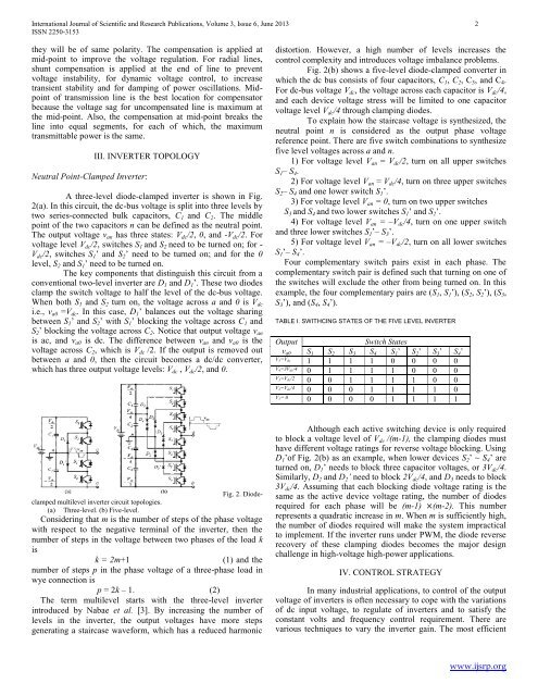
A three-level diode-clamped <strong>in</strong>verter is shown <strong>in</strong> Fig.<br />
2(a). In this circuit, the dc-bus voltage is split <strong>in</strong>to three levels by<br />
two series-connected bulk capacitors, C 1 and C 2 . The middle<br />
po<strong>in</strong>t <strong>of</strong> the two capacitors n can be def<strong>in</strong>ed as the neutral po<strong>in</strong>t.<br />
The output voltage v an has three states: V dc /2, 0, and -V dc /2. For<br />
voltage level V dc /2, switches S 1 and S 2 need to be turned on; for -<br />
V dc /2, switches S 1 ’ and S 2 ’ need to be turned on; and for the 0<br />
level, S 2 and S 1 ’ need to be turned on.<br />
The key components that dist<strong>in</strong>guish this circuit from a<br />
conventional two-level <strong>in</strong>verter are D 1 and D 1 ’. These two diodes<br />
clamp the switch voltage to half the level <strong>of</strong> the dc-bus voltage.<br />
When both S 1 and S 2 turn on, the voltage across a and 0 is V dc<br />
i.e., v a0 =V dc . In this case, D 1 ’ balances out the voltage shar<strong>in</strong>g<br />
between S 1 ’ and S 2 ’ with S 1 ’ block<strong>in</strong>g the voltage across C 1 and<br />
S 2 ’ block<strong>in</strong>g the voltage across C 2 . Notice that output voltage v an<br />
is ac, and v a0 is dc. The difference between v an and v a0 is the<br />
voltage across C 2 , which is V dc /2. If the output is removed out<br />
between a and 0, then the circuit becomes a dc/dc converter,<br />
which has three output voltage levels: V dc , V dc /2, and 0.<br />
distortion. However, a high number <strong>of</strong> levels <strong>in</strong>creases the<br />
control complexity and <strong>in</strong>troduces voltage imbalance problems.<br />
Fig. 2(b) shows a five-level diode-clamped converter <strong>in</strong><br />
which the dc bus consists <strong>of</strong> four capacitors, C 1 , C 2 , C 3 , and C 4 .<br />
For dc-bus voltage V dc , the voltage across each capacitor is V dc /4,<br />
and each device voltage stress will be limited to one capacitor<br />
voltage level V dc /4 through clamp<strong>in</strong>g diodes.<br />
To expla<strong>in</strong> how the staircase voltage is synthesized, the<br />
neutral po<strong>in</strong>t n is considered as the output phase voltage<br />
reference po<strong>in</strong>t. There are five switch comb<strong>in</strong>ations to synthesize<br />
five level voltages across a and n.<br />
1) For voltage level V an = V dc /2, turn on all upper switches<br />
S 1 – S 4 .<br />
2) For voltage level V an = V dc /4, turn on three upper switches<br />
S 2 – S 4 and one lower switch S 1 ’.<br />
3) For voltage level V an = 0, turn on two upper switches<br />
S 3 and S 4 and two lower switches S 1 ’ and S 2 ’.<br />
4) For voltage level V an = –V dc /4, turn on one upper switch<br />
and three lower switches S 1 ’– S 3 ’.<br />
5) For voltage level V an = –V dc /2, turn on all lower switches<br />
S 1 ’– S 4 ’.<br />
Four complementary switch pairs exist <strong>in</strong> each phase. The<br />
complementary switch pair is def<strong>in</strong>ed such that turn<strong>in</strong>g on one <strong>of</strong><br />
the switches will exclude the other from be<strong>in</strong>g turned on. In this<br />
example, the four complementary pairs are (S 1 , S 1 ’), (S 2 , S 2 ’), (S 3 ,<br />
S 3 ’), and (S 4 , S 4 ’).<br />
TABLE I. SWITHCING STATES OF THE FIVE LEVEL INVERTER<br />
Output<br />
v a0<br />
Switch States<br />
S 1 S 2 S 3 S 4 S 1 ’ S 2 ’ S 3 ’ S 4 ’<br />
V5=Vdc<br />
1 1 1 1 0 0 0 0<br />
V4=3Vdc/4<br />
0 1 1 1 1 0 0 0<br />
V3=Vdc/2<br />
0 0 1 1 1 1 0 0<br />
V2=Vdc/4<br />
0 0 0 1 1 1 1 0<br />
V1= 0<br />
0 0 0 0 1 1 1 1<br />
Fig. 2. <strong>Diode</strong>clamped<br />
multilevel <strong>in</strong>verter circuit topologies.<br />
(a) Three-level. (b) Five-level.<br />
Consider<strong>in</strong>g that m is the number <strong>of</strong> steps <strong>of</strong> the phase voltage<br />
with respect to the negative term<strong>in</strong>al <strong>of</strong> the <strong>in</strong>verter, then the<br />
number <strong>of</strong> steps <strong>in</strong> the voltage between two phases <strong>of</strong> the load k<br />
is<br />
k = 2m+1<br />
(1) and the<br />
number <strong>of</strong> steps p <strong>in</strong> the phase voltage <strong>of</strong> a three-phase load <strong>in</strong><br />
wye connection is<br />
p = 2k – 1. (2)<br />
The term multilevel starts with the three-level <strong>in</strong>verter<br />
<strong>in</strong>troduced by Nabae et al. [3]. By <strong>in</strong>creas<strong>in</strong>g the number <strong>of</strong><br />
levels <strong>in</strong> the <strong>in</strong>verter, the output voltages have more steps<br />
generat<strong>in</strong>g a staircase waveform, which has a reduced harmonic<br />
Although each active switch<strong>in</strong>g device is only required<br />
to block a voltage level <strong>of</strong> V dc /(m-1), the clamp<strong>in</strong>g diodes must<br />
have different voltage rat<strong>in</strong>gs for reverse voltage block<strong>in</strong>g. Us<strong>in</strong>g<br />
D 1 ’<strong>of</strong> Fig. 2(b) as an example, when lower devices S 2 ’ ~ S 4 ’ are<br />
turned on, D 1 ’ needs to block three capacitor voltages, or 3V dc /4.<br />
Similarly, D 2 and D 2 ’ need to block 2V dc /4, and D 3 needs to block<br />
3V dc /4. Assum<strong>in</strong>g that each block<strong>in</strong>g diode voltage rat<strong>in</strong>g is the<br />
same as the active device voltage rat<strong>in</strong>g, the number <strong>of</strong> diodes<br />
required for each phase will be (m-1) (m-2). This number<br />
represents a quadratic <strong>in</strong>crease <strong>in</strong> m. When m is sufficiently high,<br />
the number <strong>of</strong> diodes required will make the system impractical<br />
to implement. If the <strong>in</strong>verter runs under PWM, the diode reverse<br />
recovery <strong>of</strong> these clamp<strong>in</strong>g diodes becomes the major design<br />
challenge <strong>in</strong> high-voltage high-power applications.<br />
IV. CONTROL STRATEGY<br />
In many <strong>in</strong>dustrial applications, to control <strong>of</strong> the output<br />
voltage <strong>of</strong> <strong>in</strong>verters is <strong>of</strong>ten necessary to cope with the variations<br />
<strong>of</strong> dc <strong>in</strong>put voltage, to regulate <strong>of</strong> <strong>in</strong>verters and to satisfy the<br />
constant volts and frequency control requirement. There are<br />
various techniques to vary the <strong>in</strong>verter ga<strong>in</strong>. The most efficient<br />
www.ijsrp.<strong>org</strong>