
Create successful ePaper yourself
Turn your PDF publications into a flip-book with our unique Google optimized e-Paper software.
6. Recommended HDL <strong>Coding</strong> <strong>Style</strong>s<br />
QII51007-10.0.0<br />
This chapter provides Hardware Description Language (HDL) coding style<br />
recommendations to ensure optimal synthesis results when targeting Altera ® devices.<br />
HDL coding styles can have a significant effect on the quality of results that you<br />
achieve for programmable logic designs. Synthesis tools optimize HDL code for both<br />
logic utilization and performance, however, synthesis tools have no information<br />
about the purpose or intent of the design. The best optimizations require conscious<br />
interaction by the you, the designer.<br />
This chapter includes the following sections:<br />
■ “Quartus II Language Templates” on page 6–1<br />
■ “Using Altera Megafunctions” on page 6–2<br />
■ “Instantiating Altera Megafunctions in HDL Code” on page 6–3<br />
■ “Inferring Multiplier and DSP Functions from HDL Code” on page 6–5<br />
■ “Inferring Memory Functions from HDL Code” on page 6–12<br />
■ “<strong>Coding</strong> Guidelines for Registers and Latches” on page 6–41<br />
■ “General <strong>Coding</strong> Guidelines” on page 6–51<br />
■ “Designing with Low-Level Primitives” on page 6–72<br />
f<br />
f<br />
For additional guidelines about structuring your design, refer to the Design<br />
Recommendations for Altera Devices and the Quartus II Design Assistant chapter in<br />
volume 1 of the Quartus II Handbook. For additional handcrafted techniques you can<br />
use to optimize design blocks for the adaptive logic modules (ALMs) in many Altera<br />
devices, including a collection of circuit building blocks and related discussions, refer<br />
to the Advanced Synthesis Cookbook: A Design Guide for Stratix II, Stratix III, and<br />
Stratix IV Devices.<br />
The Altera website also provides design examples for other types of functions and to<br />
target specific applications. For more information about design examples, refer to the<br />
Design Examples page and the Reference Designs page on the Altera website.<br />
For style recommendations, options, or HDL attributes specific to your synthesis tool<br />
(including Quartus® II integrated synthesis and other EDA tools), refer to the tool<br />
vendor’s documentation or the appropriate chapter in the Synthesis section in<br />
volume 1 of the Quartus II Handbook.<br />
Quartus II Language Templates<br />
Many of the Verilog HDL and VHDL examples in this document correspond with<br />
examples in the Full Designs section of the Quartus II Templates. You can easily insert<br />
examples into your HDL source code using the Insert Template dialog box in the<br />
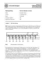
Quartus II software user interface, in Figure 6–1.<br />
© July 2010 Altera Corporation Quartus II Handbook Version 10.0 Volume 1: Design and Synthesis
6–2 Chapter 6: Recommended HDL <strong>Coding</strong> <strong>Style</strong>s<br />
Using Altera Megafunctions<br />
Figure 6–1. Insert Template Dialog Box<br />
To open the Insert Template dialog box when you have a file open in the Text Editor<br />
of the Quartus II software, on the Edit menu, click Insert Template. Alternatively, you<br />
can right-click in the Text Editor window and click Insert Template.<br />
Using Altera Megafunctions<br />
Altera provides parameterizable megafunctions that are optimized for Altera device<br />
architectures. Using megafunctions instead of coding your own logic saves valuable<br />
design time. Additionally, the Altera-provided megafunctions may offer more<br />
efficient logic synthesis and device implementation. You can scale the megafunction’s<br />
size and specify various options by setting parameters. Megafunctions include the<br />
library of parameterized modules (LPM) and Altera device-specific megafunctions.<br />
To use megafunctions in your HDL code, you can instantiate them as described in<br />
“Instantiating Altera Megafunctions in HDL Code” on page 6–3.<br />
Sometimes it is preferable to make your code independent of device family or vendor.<br />
In this case, you might not want to instantiate megafunctions directly. For some types<br />
of logic functions, such as memories and DSP functions, you can infer device specific<br />
dedicated architecture blocks instead of instantiating a megafunction. Synthesis tools,<br />
including Quartus II integrated synthesis, recognize certain types of HDL code and<br />
automatically infer the appropriate megafunction or map directly to device atoms.<br />
Synthesis tools infer megafunctions to take advantage of logic that is optimized for<br />
Altera devices or to target dedicated architectural blocks.<br />
In cases where you prefer to use generic HDL code instead of instantiating a specific<br />
function, follow the guidelines and coding examples in “Inferring Multiplier and DSP<br />
Functions from HDL Code” on page 6–5 and “Inferring Memory Functions from HDL<br />
Code” on page 6–12 to ensure your HDL code infers the appropriate function.<br />
Quartus II Handbook Version 10.0 Volume 1: Design and Synthesis © July 2010 Altera Corporation
Chapter 6: Recommended HDL <strong>Coding</strong> <strong>Style</strong>s 6–3<br />
Instantiating Altera Megafunctions in HDL Code<br />
1 You can infer or instantiate megafunctions to target some Altera device-specific<br />
architecture features such as memory and DSP blocks. You must instantiate<br />
megafunctions to target certain other device and high-speed features, such as LVDS<br />
drivers, phase-locked loops (PLLs), transceivers, and double-data rate input/output<br />
(DDIO) circuitry.<br />
Instantiating Altera Megafunctions in HDL Code<br />
The following sections describe how to use megafunctions by instantiating them in<br />
your HDL code with the following methods:<br />
■<br />
■<br />
■<br />
“Instantiating Megafunctions Using the MegaWizard Plug-In Manager”—You can<br />
use the MegaWizard Plug-In Manager to parameterize the function and create a<br />
wrapper file.<br />
“Creating a Netlist File for Other Synthesis Tools”—You can optionally create a<br />
netlist file instead of a wrapper file.<br />
“Instantiating Megafunctions Using the Port and Parameter Definition”—You can<br />
instantiate the function directly in your HDL code.<br />
Instantiating Megafunctions Using the MegaWizard Plug-In Manager<br />
Use the MegaWizard Plug-In Manager as described in this section to create<br />
megafunctions in the Quartus II software that you can instantiate in your HDL code.<br />
The MegaWizard Plug-In Manager provides a GUI to customize and parameterize<br />
megafunctions, and ensures that you set all megafunction parameters properly. When<br />
you finish setting parameters, you can specify which files you want generated.<br />
Depending on which language you choose, the MegaWizard Plug-In Manager<br />
instantiates the megafunction with the correct parameters and generates a<br />
megafunction variation file (wrapper file) in Verilog HDL (.v), VHDL (.vhd), or<br />
AHDL (.tdf), along with other supporting files.<br />
The MegaWizard Plug-In Manager provides options to create the following files:<br />
■<br />
■<br />
■<br />
■<br />
■<br />
■<br />
A sample instantiation template for the language of the variation file, either<br />
_inst.v, or _inst.vhd, or _inst.tdf.<br />
Component Declaration File (.cmp) that can be used in VHDL Design Files.<br />
ADHL Include File (.inc) that can be used in Text Design Files (.tdf).<br />
Quartus II Block Symbol File (.bsf) for schematic designs.<br />
Verilog HDL module declaration file that can be used when instantiating the<br />
megafunction as a black box in a other EDA synthesis tool (_bb.v).<br />
If you enable the option to generate a synthesis timing and resource estimation<br />
netlist, the MegaWizard Plug-In Manager generates an additional synthesis netlist<br />
file (_syn.v). Refer to “Creating a Netlist File for Other Synthesis Tools” on<br />
page 6–4 for details.<br />
Table 6–1 lists and describes the files generated by the MegaWizard Plug-In Manager.<br />
© July 2010 Altera Corporation Quartus II Handbook Version 10.0 Volume 1: Design and Synthesis
6–4 Chapter 6: Recommended HDL <strong>Coding</strong> <strong>Style</strong>s<br />
Instantiating Altera Megafunctions in HDL Code<br />
Table 6–1. MegaWizard Plug-In Manager Generated Files<br />
File<br />
.v (1)<br />
.vhd (1)<br />
.tdf (1)<br />
.inc<br />
.cmp<br />
.bsf<br />
_inst.v<br />
_inst.vhd<br />
_inst.tdf<br />
_bb.v<br />
_syn.v (2)<br />
Creating a Netlist File for Other Synthesis Tools<br />
Description<br />
Verilog HDL Variation Wrapper File—Megafunction wrapper file for instantiation in a<br />
Verilog HDL design.<br />
VHDL Variation Wrapper File—Megafunction wrapper file for instantiation in a VHDL design.<br />
AHDL Variation Wrapper File—Megafunction wrapper file for instantiation in an AHDL design.<br />
ADHL Include File—Used in AHDL designs.<br />
Component Declaration File—Used in VHDL designs.<br />
Block Symbol File—Used in Quartus II Block Design Files (.bdf).<br />
Verilog HDL Instantiation Template—Sample Verilog HDL instantiation of the module in the<br />
megafunction wrapper file.<br />
VHDL Instantiation Template—Sample VHDL instantiation of the entity in the megafunction<br />
wrapper file.<br />
Text Design File Instantiation Template—Sample AHDL instantiation of the subdesign in the<br />
megafunction wrapper file.<br />
Black box Verilog HDL Module Declaration—Hollow-body module declaration that can be<br />
used in Verilog HDL designs to specify port directions when creating black boxes in<br />
third-party synthesis tools.<br />
Synthesis timing and resource estimation netlist—Megafunction netlist may be used by other<br />
EDA synthesis tools to improve timing and resource estimations.<br />
Notes to Table 6–1:<br />
(1) The MegaWizard Plug-In Manager generates either the .v, .vhd, or .tdf file, depending on the language you select for the output file on the<br />
megafunction-selection page of the wizard.<br />
(2) The MegaWizard Plug-In Manager generates this file only if you turn on the Generate netlist option under Timing and resource estimation on<br />
the EDA page of the wizard.<br />
When you use certain megafunctions with other EDA synthesis tools (that is, tools<br />
other than Quartus II integrated synthesis), you can optionally create a netlist for<br />
timing and resource estimation instead of a wrapper file.<br />
The netlist file is a representation of the customized logic used in the Quartus II<br />
software. The file provides the connectivity of architectural elements in the<br />
megafunction but may not represent true functionality. This information enables<br />
certain other EDA synthesis tools to better report timing and resource estimates. In<br />
addition, synthesis tools can use the timing information to focus timing-driven<br />
optimizations and improve the quality of results.<br />
To generate the netlist, turn on Generate netlist under Timing and resource<br />
estimation on the EDA page of the MegaWizard Plug-In Manager. The netlist file is<br />
called _syn.v. If you use this netlist for synthesis, you must include the<br />
megafunction wrapper file, either .v or .vhd, for placement<br />
and routing in the project created with the Quartus II software.<br />
Because your synthesis tool may call the Quartus II software in the background to<br />
generate this netlist, turning on this option might not be required.<br />
Quartus II Handbook Version 10.0 Volume 1: Design and Synthesis © July 2010 Altera Corporation
Chapter 6: Recommended HDL <strong>Coding</strong> <strong>Style</strong>s 6–5<br />
Inferring Multiplier and DSP Functions from HDL Code<br />
f<br />
For information about support for timing and resource estimation netlists in your<br />
synthesis tool, refer to the tool vendor’s documentation or the appropriate chapter in<br />
the Synthesis section in volume 1 of the Quartus II Handbook.<br />
Instantiating Megafunctions Using the Port and Parameter Definition<br />
You can instantiate the megafunction directly in your Verilog HDL, VHDL, or AHDL<br />
code by calling the megafunction and setting its parameters as you would any other<br />
module, component, or subdesign.<br />
f<br />
For a list of the megafunction ports and parameters, refer to the specific megafunction<br />
in the Quartus II Help. You can also refer to the IP and Megafunction page on the<br />
Altera website.<br />
1 Altera strongly recommends that you use the MegaWizard Plug-In Manager for<br />
complex megafunctions such as PLLs, transceivers, and LVDS drivers. For details<br />
about using the MegaWizard Plug-In Manager, refer to “Instantiating Megafunctions<br />
Using the MegaWizard Plug-In Manager” on page 6–3.<br />
Inferring Multiplier and DSP Functions from HDL Code<br />
The following sections describe how to infer multiplier and DSP functions from<br />
generic HDL code, and, if applicable, how to target the dedicated DSP block<br />
architecture in Altera devices:<br />
■<br />
■<br />
“Inferring Multipliers from HDL Code”<br />
“Inferring Multiply-Accumulators and Multiply-Adders from HDL Code” on<br />
page 6–7<br />
f<br />
f<br />
For synthesis tool features and options, refer to your synthesis tool documentation or<br />
the appropriate chapter in the Synthesis section in volume 1 of the Quartus II Handbook.<br />
For more design examples involving advanced multiply functions and complex DSP<br />
functions, refer to the DSP Design Examples page on the Altera website.<br />
Inferring Multipliers from HDL Code<br />
To infer multiplier functions, synthesis tools look for multipliers and convert them to<br />
LPM_MULT or ALTMULT_ADD megafunctions, or may map them directly to device<br />
atoms. For devices with DSP blocks, the software can implement the function in a DSP<br />
block instead of logic, depending on device utilization. The Quartus II Fitter can also<br />
place input and output registers in DSP blocks (that is, perform register packing) to<br />
improve performance and area utilization.<br />
f<br />
For additional information about the DSP block and the supported functions, refer to<br />
the appropriate Altera device family handbook and the Altera DSP Solutions Center<br />
website.<br />
© July 2010 Altera Corporation Quartus II Handbook Version 10.0 Volume 1: Design and Synthesis
6–6 Chapter 6: Recommended HDL <strong>Coding</strong> <strong>Style</strong>s<br />
Inferring Multiplier and DSP Functions from HDL Code<br />
Example 6–1 and Example 6–2 show Verilog HDL code examples, and Example 6–3<br />
and Example 6–4 show VHDL code examples, for unsigned and signed multipliers<br />
that synthesis tools can infer as a megafunction or DSP block atoms. Each example fits<br />
into one DSP block element. In addition, when register packing occurs, no extra logic<br />
cells for registers are required.<br />
1 The signed declaration in Verilog HDL is a feature of the Verilog 2001 Standard.<br />
Example 6–1. Verilog HDL Unsigned Multiplier<br />
module unsigned_mult (out, a, b);<br />
output [15:0] out;<br />
input [7:0] a;<br />
input [7:0] b;<br />
assign out = a * b;<br />
endmodule<br />
Example 6–2. Verilog HDL Signed Multiplier with Input and Output Registers (Pipelining = 2)<br />
module signed_mult (out, clk, a, b);<br />
output [15:0] out;<br />
input clk;<br />
input signed [7:0] a;<br />
input signed [7:0] b;<br />
reg signed [7:0] a_reg;<br />
reg signed [7:0] b_reg;<br />
reg signed [15:0] out;<br />
wire signed [15:0] mult_out;<br />
assign mult_out = a_reg * b_reg;<br />
always @ (posedge clk)<br />
begin<br />
a_reg
Chapter 6: Recommended HDL <strong>Coding</strong> <strong>Style</strong>s 6–7<br />
Inferring Multiplier and DSP Functions from HDL Code<br />
Example 6–3. VHDL Unsigned Multiplier with Input and Output Registers (Pipelining = 2)<br />
LIBRARY ieee;<br />
USE ieee.std_logic_1164.all;<br />
USE ieee.numeric_std.all;<br />
ENTITY unsigned_mult IS<br />
PORT (<br />
a: IN UNSIGNED (7 DOWNTO 0);<br />
b: IN UNSIGNED (7 DOWNTO 0);<br />
clk: IN STD_LOGIC;<br />
aclr: IN STD_LOGIC;<br />
result: OUT UNSIGNED (15 DOWNTO 0)<br />
);<br />
END unsigned_mult;<br />
ARCHITECTURE rtl OF unsigned_mult IS<br />
SIGNAL a_reg, b_reg: UNSIGNED (7 DOWNTO 0);<br />
BEGIN<br />
PROCESS (clk, aclr)<br />
BEGIN<br />
IF (aclr ='1') THEN<br />
a_reg '0');<br />
b_reg '0');<br />
result '0');<br />
ELSIF (clk'event AND clk = '1') THEN<br />
a_reg
6–8 Chapter 6: Recommended HDL <strong>Coding</strong> <strong>Style</strong>s<br />
Inferring Multiplier and DSP Functions from HDL Code<br />
1 Synthesis tools infer multiply-accumulator and multiply-adder functions only if the<br />
Altera device family has dedicated DSP blocks that support these functions.<br />
A simple multiply-accumulator consists of a multiplier feeding an addition operator.<br />
The addition operator feeds a set of registers that then feeds the second input to the<br />
addition operator. A simple multiply-adder consists of two to four multipliers feeding<br />
one or two levels of addition, subtraction, or addition/subtraction operators.<br />
Addition is always the second-level operator, if it is used. In addition to the<br />
multiply-accumulator and multiply-adder, the Quartus II Fitter also places input and<br />
output registers into the DSP blocks to pack registers and improve performance and<br />
area utilization.<br />
Some device families offer additional advanced multiply-add and accumulate<br />
functions, such as complex multiplication, input shift register, or larger<br />
multiplications.<br />
f<br />
For details about advanced DSP block features, refer to the appropriate device<br />
handbook. For more design examples involving DSP functions and inferring<br />
advanced features in the multiply-add and multiply-accumulate circuitry, refer to the<br />
DSP Design Examples page on Altera’s website.<br />
The Verilog HDL and VHDL code samples in Example 6–5 through Example 6–8 on<br />
pages 6–9 through 6–12 infer multiply-accumulators and multiply-adders with input,<br />
output, and pipeline registers, as well as an optional asynchronous clear signal. Using<br />
the three sets of registers provides the best performance through the function, with a<br />
latency of three. You can remove the registers in your design to reduce the latency.<br />
Quartus II Handbook Version 10.0 Volume 1: Design and Synthesis © July 2010 Altera Corporation
Chapter 6: Recommended HDL <strong>Coding</strong> <strong>Style</strong>s 6–9<br />
Inferring Multiplier and DSP Functions from HDL Code<br />
Example 6–5. Verilog HDL Unsigned Multiply-Accumulator<br />
module unsig_altmult_accum (dataout, dataa, datab, clk, aclr, clken);<br />
input [7:0] dataa, datab;<br />
input clk, aclr, clken;<br />
output reg[16:0] dataout;<br />
reg [7:0] dataa_reg, datab_reg;<br />
reg [15:0] multa_reg;<br />
wire [15:0] multa;<br />
wire [16:0] adder_out;<br />
assign multa = dataa_reg * datab_reg;<br />
assign adder_out = multa_reg + dataout;<br />
always @ (posedge clk or posedge aclr)<br />
begin<br />
if (aclr)<br />
begin<br />
dataa_reg
6–10 Chapter 6: Recommended HDL <strong>Coding</strong> <strong>Style</strong>s<br />
Inferring Multiplier and DSP Functions from HDL Code<br />
Example 6–6. Verilog HDL Signed Multiply-Adder<br />
module sig_altmult_add (dataa, datab, datac, datad, clock, aclr,<br />
result);<br />
input signed [15:0] dataa, datab, datac, datad;<br />
input clock, aclr;<br />
output reg signed [32:0] result;<br />
reg signed [15:0] dataa_reg, datab_reg, datac_reg, datad_reg;<br />
reg signed [31:0] mult0_result, mult1_result;<br />
always @ (posedge clock or posedge aclr) begin<br />
if (aclr) begin<br />
dataa_reg
Chapter 6: Recommended HDL <strong>Coding</strong> <strong>Style</strong>s 6–11<br />
Inferring Multiplier and DSP Functions from HDL Code<br />
Example 6–7. VHDL Signed Multiply-Accumulator<br />
LIBRARY ieee;<br />
USE ieee.std_logic_1164.all;<br />
USE ieee.numeric_std.all;<br />
ENTITY sig_altmult_accum IS<br />
PORT (<br />
a: IN SIGNED(7 DOWNTO 0);<br />
b: IN SIGNED (7 DOWNTO 0);<br />
clk: IN STD_LOGIC;<br />
aclr: IN STD_LOGIC;<br />
accum_out: OUT SIGNED (15 DOWNTO 0)<br />
) ;<br />
END sig_altmult_accum;<br />
ARCHITECTURE rtl OF sig_altmult_accum IS<br />
SIGNAL a_reg, b_reg: SIGNED (7 DOWNTO 0);<br />
SIGNAL pdt_reg: SIGNED (15 DOWNTO 0);<br />
SIGNAL adder_out: SIGNED (15 DOWNTO 0);<br />
BEGIN<br />
PROCESS (clk, aclr)<br />
BEGIN<br />
IF (aclr = '1') then<br />
a_reg '0');<br />
b_reg '0');<br />
pdt_reg '0');<br />
adder_out '0');<br />
ELSIF (clk'event and clk = '1') THEN<br />
a_reg
6–12 Chapter 6: Recommended HDL <strong>Coding</strong> <strong>Style</strong>s<br />
Inferring Memory Functions from HDL Code<br />
Example 6–8. VHDL Unsigned Multiply-Adder<br />
LIBRARY ieee;<br />
USE ieee.std_logic_1164.all;<br />
USE ieee.numeric_std.all;<br />
ENTITY unsignedmult_add IS<br />
PORT (<br />
a: IN UNSIGNED (7 DOWNTO 0);<br />
b: IN UNSIGNED (7 DOWNTO 0);<br />
c: IN UNSIGNED (7 DOWNTO 0);<br />
d: IN UNSIGNED (7 DOWNTO 0);<br />
clk: IN STD_LOGIC;<br />
aclr: IN STD_LOGIC;<br />
result: OUT UNSIGNED (15 DOWNTO 0)<br />
);<br />
END unsignedmult_add;<br />
ARCHITECTURE rtl OF unsignedmult_add IS<br />
SIGNAL a_reg, b_reg, c_reg, d_reg: UNSIGNED (7 DOWNTO 0);<br />
SIGNAL pdt_reg, pdt2_reg: UNSIGNED (15 DOWNTO 0);<br />
SIGNAL result_reg: UNSIGNED (15 DOWNTO 0);<br />
BEGIN<br />
PROCESS (clk, aclr)<br />
BEGIN<br />
IF (aclr = '1') THEN<br />
a_reg '0');<br />
b_reg '0');<br />
c_reg '0');<br />
d_reg '0');<br />
pdt_reg '0');<br />
pdt2_reg '0');<br />
ELSIF (clk'event AND clk = '1') THEN<br />
a_reg
Chapter 6: Recommended HDL <strong>Coding</strong> <strong>Style</strong>s 6–13<br />
Inferring Memory Functions from HDL Code<br />
Altera’s dedicated memory architecture offers a number of advanced features that can<br />
be easily targeted using the MegaWizard Plug-In Manager, as described in<br />
“Instantiating Altera Megafunctions in HDL Code” on page 6–3. The coding<br />
recommendations in the following sections provide portable examples of generic<br />
HDL code that infer the appropriate megafunction. However, if you want to use some<br />
of the advanced memory features in Altera devices, consider using the megafunction<br />
directly so that you can control the ports and parameters more easily.<br />
Inferring RAM functions from HDL Code<br />
To infer RAM functions, synthesis tools detect sets of registers and logic that can be<br />
replaced with the ALTSYNCRAM or ALTDPRAM megafunctions for device families<br />
that have dedicated RAM blocks, or may map them directly to device memory atoms.<br />
Tools typically consider all signals and variables that have a multi-dimensional array<br />
type and then create a RAM block, if applicable, based on the way the signals,<br />
variables, or both are assigned, referenced, or both in the HDL source description.<br />
Standard synthesis tools recognize single-port and simple dual-port (one read port<br />
and one write port) RAM blocks. Some tools (such as the Quartus II software) also<br />
recognize true dual-port (two read ports and two write ports) RAM blocks that map<br />
to the memory blocks in certain Altera devices.<br />
Some tools (such as the Quartus II software) also infer memory blocks for array<br />
variables and signals that are referenced (read/written) by two indices, to recognize<br />
mixed-width and byte-enabled RAMs for certain coding styles.<br />
1 If your design contains a RAM block that your synthesis tool does not recognize and<br />
infer, the design might require a large amount of system memory that can potentially<br />
cause compilation problems.<br />
When you use a formal verification flow, Altera recommends that you create RAM<br />
blocks in separate entities or modules that contain only the RAM logic. In certain<br />
formal verification flows, for example, when using Quartus II integrated synthesis,<br />
the entity or module containing the inferred RAM is put into a black box<br />
automatically because formal verification tools do not support RAM blocks. The<br />
Quartus II software issues a warning message when this situation occurs. If the entity<br />
or module contains any additional logic outside the RAM block, this logic cannot be<br />
verified because it also must be treated as a black box for formal verification.<br />
The following subsections present several guidelines for inferring RAM functions that<br />
match the dedicated memory architecture in Altera devices, and then provide<br />
recommended HDL code for different types of memory logic.<br />
Use Synchronous Memory Blocks<br />
Altera recommends using synchronous memory blocks for Altera designs. Because<br />
memory blocks in the newest devices from Altera are synchronous, RAM designs that<br />
are targeted towards architectures that contain these dedicated memory blocks must<br />
be synchronous to be mapped directly into the device architecture. For these devices,<br />
asynchronous memory logic is implemented in regular logic cells.<br />
© July 2010 Altera Corporation Quartus II Handbook Version 10.0 Volume 1: Design and Synthesis
6–14 Chapter 6: Recommended HDL <strong>Coding</strong> <strong>Style</strong>s<br />
Inferring Memory Functions from HDL Code<br />
Synchronous memory offers several advantages over asynchronous memory,<br />
including higher frequencies and thus higher memory bandwidth, increased<br />
reliability, and less standby power. In many designs with asynchronous memory, the<br />
memory interfaces with synchronous logic so that the conversion to synchronous<br />
memory design is straightforward. To convert asynchronous memory you can move<br />
registers from the data path into the memory block.<br />
Synchronous memories are supported in all Altera device families. A memory block is<br />
considered synchronous if it uses one of the following read behaviors:<br />
■<br />
■<br />
Memory read occurs in a Verilog always block with a clock signal or a VHDL<br />
clocked process. The recommended coding style for synchronous memories is to<br />
create your design with a registered read output.<br />
Memory read occurs outside a clocked block, but there is a synchronous read<br />
address (that is, the address used in the read statement is registered). This type of<br />
logic is not always inferred as a memory block, or may require external bypass<br />
logic, depending on the target device architecture.<br />
1 The synchronous memory structures in Altera devices can differ from the structures<br />
in other vendors’ devices. For best results, match your design to the target device<br />
architecture.<br />
Later subsections provide coding recommendations for various memory types. All of<br />
these examples are synchronous to ensure that they can be directly mapped into the<br />
dedicated memory architecture available in Altera FPGAs.<br />
f<br />
For additional information about the dedicated memory blocks in your specific<br />
device, refer to the appropriate Altera device family data sheet on the Altera website<br />
at www.altera.com.<br />
Avoid Unsupported Reset and Control Conditions<br />
To ensure that your HDL code can be implemented in the target device architecture,<br />
avoid unsupported reset conditions or other control logic that does not exist in the<br />
device architecture.<br />
The RAM contents of Altera memory blocks cannot be cleared with a reset signal<br />
during device operation. If your HDL code describes a RAM with a reset signal for the<br />
RAM contents, the logic is implemented in regular logic cells instead of a memory<br />
block. Altera recommends against putting RAM read or write operations in an<br />
always block or process block with a reset signal. If you want to specify memory<br />
contents, initialize the memory as described in “Specifying Initial Memory Contents<br />
at Power-Up” on page 6–31 or write the data to the RAM during device operation.<br />
Example 6–9 shows an example of undesirable code where there is a reset signal that<br />
clears part of the RAM contents. Avoid this coding style because it is not supported in<br />
Altera memories.<br />
Quartus II Handbook Version 10.0 Volume 1: Design and Synthesis © July 2010 Altera Corporation
Chapter 6: Recommended HDL <strong>Coding</strong> <strong>Style</strong>s 6–15<br />
Inferring Memory Functions from HDL Code<br />
Example 6–9. Verilog RAM with Reset Signal that Clears RAM Contents: Not Supported in Device<br />
Architecture<br />
module clear_ram<br />
(<br />
input clock, reset, we,<br />
input [7:0] data_in,<br />
input [4:0] address,<br />
output reg [7:0] data_out<br />
);<br />
reg [7:0] mem [0:31];<br />
integer i;<br />
always @ (posedge clock or posedge reset)<br />
begin<br />
if (reset == 1'b1)<br />
mem[address]
6–16 Chapter 6: Recommended HDL <strong>Coding</strong> <strong>Style</strong>s<br />
Inferring Memory Functions from HDL Code<br />
In addition to reset signals, other control logic can prevent memory logic from being<br />
inferred as a memory block. For example, you cannot use a clock enable on the read<br />
address registers in Stratix ® devices because doing so affects the output latch of the<br />
RAM, and therefore the synthesized result in the device RAM architecture would not<br />
match the HDL description. You can use the address stall feature as a read address<br />
clock enable in Stratix II, Cyclone ® II, Arria ® GX, and other newer devices to avoid this<br />
limitation. Check the documentation for your device architecture to ensure that your<br />
code matches the hardware available in the device.<br />
Check Read-During-Write Behavior<br />
It is important to check the read-during-write behavior of the memory block<br />
described in your HDL design as compared to the behavior in your target device<br />
architecture. Your HDL source code specifies the memory behavior when you read<br />
and write from the same memory address in the same clock cycle. The code specifies<br />
that the read returns either the old data at the address, or the new data being written<br />
to the address. This behavior is referred to as the read-during-write behavior of the<br />
memory block. Altera memory blocks have different read-during-write behavior<br />
depending on the target device family, memory mode, and block type.<br />
Synthesis tools map an HDL design into the target device architecture, with the goal<br />
of maintaining the functionality described in your source code. Therefore, if your<br />
source code specifies unsupported read-during-write behavior for the device RAM<br />
blocks, the software must implement the logic outside the RAM hardware in regular<br />
logic cells.<br />
One common problem occurs when there is a continuous read in the HDL code, as in<br />
the following examples. You should avoid using these coding styles:<br />
//Verilog HDL concurrent signal assignment<br />
assign q = ram[raddr_reg];<br />
-- VHDL concurrent signal assignment<br />
q
Chapter 6: Recommended HDL <strong>Coding</strong> <strong>Style</strong>s 6–17<br />
Inferring Memory Functions from HDL Code<br />
In many synthesis tools, you can specify that the read-during-write behavior is not<br />
important to your design; for example, if you never read from the same address to<br />
which you write in the same clock cycle. For Quartus II integrated synthesis, add the<br />
synthesis attribute ramstyle set to "no_rw_check" to allow the software to choose<br />
the read-during-write behavior of a RAM, rather than use the behavior specified by<br />
your HDL code. In some cases, this attribute prevents the synthesis tool from using<br />
extra logic to implement the memory block, or can allow memory inference when it<br />
would otherwise be impossible.<br />
Synchronous RAM blocks require a synchronous read, so Quartus II integrated<br />
synthesis packs either data output registers or read address registers into the RAM<br />
block. When the read address registers are packed into the RAM block, the read<br />
address signals connected to the RAM block contain the next value of the read<br />
address signals indexing the HDL variable, which impacts which clock cycle the read<br />
and the write occur and changes the read-during-write conditions. Therefore, bypass<br />
logic may still be added to the design to preserve the read-during-write behavior,<br />
even if the "no_rw_check" attribute is set.<br />
f<br />
For more information about attribute syntax, the no_rw_check attribute value, or<br />
specific options for your synthesis tool, refer to your synthesis tool documentation or<br />
the appropriate chapter in the Synthesis section in volume 1 of the Quartus II Handbook.<br />
The next subsection describes how you control the logic implementation in the Altera<br />
device, and the following subsections provide coding recommendations for various<br />
memory types. Each example describes the read-during-write behavior and addresses<br />
the support for the memory type in Altera devices.<br />
Controlling Inference and Implementation in Device RAM Blocks<br />
Tools usually do not infer small RAM blocks because small RAM blocks typically can<br />
be implemented more efficiently using the registers in regular logic. If you are using<br />
Quartus II integrated synthesis, you can direct the software to infer RAM blocks for<br />
all sizes with the Allow Any RAM Size for Recognition option in the More Analysis<br />
& Synthesis Settings dialog box.<br />
Some synthesis tools provide options to control the implementation of inferred RAM<br />
blocks for Altera devices with synchronous memory blocks. For example, Quartus II<br />
integrated synthesis provides the ramstyle synthesis attribute to specify the type of<br />
memory block or to specify the use of regular logic instead of a dedicated memory<br />
block. Quartus II integrated synthesis does not map inferred memory into MLABs<br />
unless the HDL code specifies the appropriate ramstyle attribute, although the<br />
Fitter may map some memories to MLABs.<br />
f<br />
For details about using the ramstyle attribute, refer to the Quartus II Integrated<br />
Synthesis chapter in volume 1 of the Quartus II Handbook. For information about<br />
synthesis attributes in other synthesis tools, refer to the appropriate chapter in the<br />
Synthesis section in volume 1 of the Quartus II Handbook.<br />
© July 2010 Altera Corporation Quartus II Handbook Version 10.0 Volume 1: Design and Synthesis
6–18 Chapter 6: Recommended HDL <strong>Coding</strong> <strong>Style</strong>s<br />
Inferring Memory Functions from HDL Code<br />
If you want to control the implementation after the RAM function is inferred during<br />
synthesis, you can set the ram_block_type parameter of the ALTSYNCRAM<br />
megafunction. In the Assignment Editor, select Parameters in the Categories list. You<br />
can use the Node Finder or drag the appropriate instance from the Project Navigator<br />
window to enter the RAM hierarchical instance name. Type ram_block_type as the<br />
Parameter Name and type one of the following memory types supported by your<br />
target device family in the Value field: "M-RAM", "M4K", "M20K", "M512", "M9K",<br />
"M144K", or "MLAB".<br />
You can also specify the maximum depth of memory blocks used to infer RAM or<br />
ROM in your design. Apply the max_depth synthesis attribute to the declaration of a<br />
variable that represents a RAM or ROM in your design file. For example:<br />
// Limit the depth of the memory blocks implement "ram" to 512<br />
// This forces the software to use two M512 blocks instead of one M4K<br />
block to implement this RAM<br />
(* max_depth = 512 *) reg [7:0] ram[0:1023];<br />
Single-Clock Synchronous RAM with Old Data Read-During-Write Behavior<br />
The code examples in this section show Verilog HDL and VHDL code that infers<br />
simple dual-port, single-clock synchronous RAM. Single-port RAM blocks use a<br />
similar coding style.<br />
The read-during-write behavior in these examples is to read the old data at the<br />
memory address. Refer to “Check Read-During-Write Behavior” on page 6–16 for<br />
details. Altera recommends that you use the Old Data Read-During-Write coding<br />
style for most RAM blocks as long as your design does not require the RAM location’s<br />
new value when you perform a simultaneous read and write to that RAM location.<br />
For best performance in MLAB memories, use the appropriate attribute so that your<br />
design does not depend on the read data during a write operation.<br />
If you require that the read-during-write results in new data, refer to “Single-Clock<br />
Synchronous RAM with New Data Read-During-Write Behavior” on page 6–19.<br />
The simple dual-port RAM code samples in Example 6–11 and Example 6–12 map<br />
directly into Altera synchronous memory.<br />
Single-port versions of memory blocks (that is, using the same read address and write<br />
address signals) can allow better RAM utilization than dual-port memory blocks,<br />
depending on the device family.<br />
Example 6–11. Verilog HDL Single-Clock Simple Dual-Port Synchronous RAM with Old Data<br />
Read-During-Write Behavior<br />
module single_clk_ram(<br />
output reg [7:0] q,<br />
input [7:0] d,<br />
input [6:0] write_address, read_address,<br />
input we, clk<br />
);<br />
reg [7:0] mem [127:0];<br />
always @ (posedge clk) begin<br />
if (we)<br />
mem[write_address]
Chapter 6: Recommended HDL <strong>Coding</strong> <strong>Style</strong>s 6–19<br />
Inferring Memory Functions from HDL Code<br />
Example 6–12. VHDL Single-Clock Simple Dual-Port Synchronous RAM with Old Data<br />
Read-During-Write Behavior<br />
LIBRARY ieee;<br />
USE ieee.std_logic_1164.all;<br />
ENTITY single_clock_ram IS<br />
PORT (<br />
clock: IN STD_LOGIC;<br />
data: IN STD_LOGIC_VECTOR (2 DOWNTO 0);<br />
write_address: IN INTEGER RANGE 0 to 31;<br />
read_address: IN INTEGER RANGE 0 to 31;<br />
we: IN STD_LOGIC;<br />
q: OUT STD_LOGIC_VECTOR (2 DOWNTO 0)<br />
);<br />
END single_clock_ram;<br />
ARCHITECTURE rtl OF single_clock_ram IS<br />
TYPE MEM IS ARRAY(0 TO 31) OF STD_LOGIC_VECTOR(2 DOWNTO 0);<br />
SIGNAL ram_block: MEM;<br />
BEGIN<br />
PROCESS (clock)<br />
BEGIN<br />
IF (clock'event AND clock = '1') THEN<br />
IF (we = '1') THEN<br />
ram_block(write_address)
6–20 Chapter 6: Recommended HDL <strong>Coding</strong> <strong>Style</strong>s<br />
Inferring Memory Functions from HDL Code<br />
Example 6–13. Verilog HDL Single-Clock Simple Dual-Port Synchronous RAM with New Data<br />
Read-During-Write Behavior<br />
module single_clock_wr_ram(<br />
output reg [7:0] q,<br />
input [7:0] d,<br />
input [6:0] write_address, read_address,<br />
input we, clk<br />
);<br />
reg [7:0] mem [127:0];<br />
always @ (posedge clk) begin<br />
if (we)<br />
mem[write_address] = d;<br />
q = mem[read_address]; // q does get d in this clock cycle if<br />
we is high<br />
end<br />
endmodule<br />
1 Example 6–13 is similar to Example 6–11, but Example 6–13 uses a blocking<br />
assignment for the write so that the data is assigned immediately.<br />
An alternative way to create a single-clock RAM is to use an assign statement to read<br />
the address of mem to create the output q, as shown in the following coding style<br />
example. By itself, the code describes new data read-during-write behavior. However,<br />
if the RAM output feeds a register in another hierarchy, a read-during-write results in<br />
the old data. Synthesis tools may not infer a RAM block if the tool cannot determine<br />
which behavior is described, such as when the memory feeds a hard hierarchical<br />
partition boundary. For this reason, avoid using this alternate type of coding style:<br />
reg [7:0] mem [127:0];<br />
reg [6:0] read_address_reg;<br />
always @ (posedge clk) begin<br />
if (we)<br />
mem[write_address]
Chapter 6: Recommended HDL <strong>Coding</strong> <strong>Style</strong>s 6–21<br />
Inferring Memory Functions from HDL Code<br />
The VHDL sample in Example 6–14 uses a concurrent signal assignment to read from<br />
the RAM. By itself, this example describes new data read-during-write behavior.<br />
However, if the RAM output feeds a register in another hierarchy, a read-during-write<br />
results in the old data. Synthesis tools may not infer a RAM block if the tool cannot<br />
determine which behavior is described, such as when the memory feeds a hard<br />
hierarchical partition boundary.<br />
Example 6–14. VHDL Single-Clock Simple Dual-Port Synchronous RAM with New Data<br />
Read-During-Write Behavior<br />
LIBRARY ieee;<br />
USE ieee.std_logic_1164.all;<br />
ENTITY single_clock_rw_ram IS<br />
PORT (<br />
clock: IN STD_LOGIC;<br />
data: IN STD_LOGIC_VECTOR (2 DOWNTO 0);<br />
write_address: IN INTEGER RANGE 0 to 31;<br />
read_address: IN INTEGER RANGE 0 to 31;<br />
we: IN STD_LOGIC;<br />
q: OUT STD_LOGIC_VECTOR (2 DOWNTO 0)<br />
);<br />
END single_clock_rw_ram;<br />
ARCHITECTURE rtl OF single_clock_rw_ram IS<br />
TYPE MEM IS ARRAY(0 TO 31) OF STD_LOGIC_VECTOR(2 DOWNTO 0);<br />
SIGNAL ram_block: MEM;<br />
SIGNAL read_address_reg: INTEGER RANGE 0 to 31;<br />
BEGIN<br />
PROCESS (clock)<br />
BEGIN<br />
IF (clock'event AND clock = '1') THEN<br />
IF (we = '1') THEN<br />
ram_block(write_address)
6–22 Chapter 6: Recommended HDL <strong>Coding</strong> <strong>Style</strong>s<br />
Inferring Memory Functions from HDL Code<br />
The code samples in Example 6–15 and Example 6–16 show Verilog HDL and VHDL<br />
code that infers dual-clock synchronous RAM. The exact behavior depends on the<br />
relationship between the clocks.<br />
Example 6–15. Verilog HDL Simple Dual-Port, Dual-Clock Synchronous RAM<br />
module dual_clock_ram(<br />
output reg [7:0] q,<br />
input [7:0] d,<br />
input [6:0] write_address, read_address,<br />
input we, clk1, clk2<br />
);<br />
reg [6:0] read_address_reg;<br />
reg [7:0] mem [127:0];<br />
always @ (posedge clk1)<br />
begin<br />
if (we)<br />
mem[write_address]
Chapter 6: Recommended HDL <strong>Coding</strong> <strong>Style</strong>s 6–23<br />
Inferring Memory Functions from HDL Code<br />
True Dual-Port Synchronous RAM<br />
The code examples in this section show Verilog HDL and VHDL code that infers true<br />
dual-port synchronous RAM. Different synthesis tools may differ in their support for<br />
these types of memories. This section describes the inference rules for Quartus II<br />
integrated synthesis. This type of RAM inference is supported only for the Arria GX,<br />
Stratix, and Cyclone series of devices.<br />
Altera synchronous memory blocks have two independent address ports, allowing<br />
for operations on two unique addresses simultaneously. A read operation and a write<br />
operation can share the same port if they share the same address. The Quartus II<br />
software infers true dual-port RAMs in Verilog HDL and VHDL with any<br />
combination of independent read or write operations in the same clock cycle, with at<br />
most two unique port addresses, performing two reads and one write, two writes and<br />
one read, or two writes and two reads in one clock cycle with one or two unique<br />
addresses.<br />
In the synchronous RAM block architecture, there is no priority between the two<br />
ports. Therefore, if you write to the same location on both ports at the same time, the<br />
result is indeterminate in the device architecture. You must ensure your HDL code<br />
does not imply priority for writes to the memory block, if you want the design to be<br />
implemented in a dedicated hardware memory block. For example, if both ports are<br />
defined in the same process block, the code is synthesized and simulated sequentially<br />
so that there is a priority between the two ports. If your code does imply a priority, the<br />
logic cannot be implemented in the device RAM blocks and is implemented in regular<br />
logic cells.<br />
You must also consider the read-during-write behavior of the RAM block to ensure<br />
that it can be mapped directly to the device RAM architecture. Refer to “Check<br />
Read-During-Write Behavior” on page 6–16 for details.<br />
When a read and write operation occurs on the same port for the same address, the<br />
read operation may behave as follows:<br />
■<br />
■<br />
Read new data—This mode matches the behavior of synchronous memory blocks.<br />
Read old data—This mode is supported only by synchronous memory blocks in<br />
Arria II GX, Cyclone III, Stratix III, and newer device families. This behavior is not<br />
possible in memory blocks of older families.<br />
When a read and write operation occurs on different ports for the same address (also<br />
known as mixed port), the read operation may behave as follows:<br />
■<br />
■<br />
Read new data—Quartus II integrated synthesis supports this mode by creating<br />
bypass logic around the synchronous memory block.<br />
Read old data—This behavior is supported by synchronous memory blocks.<br />
The Verilog HDL single-clock code sample in Example 6–17 maps directly into Altera<br />
synchronous memory. When a read and write operation occurs on the same port for<br />
the same address, the new data being written to the memory is read. When a read and<br />
write operation occurs on different ports for the same address, the old data in the<br />
memory is read. Simultaneous writes to the same location on both ports results in<br />
indeterminate behavior.<br />
A dual-clock version of this design describes the same behavior, but the memory in<br />
the target device will have undefined mixed port read-during-write behavior because<br />
it depends on the relationship between the clocks.<br />
© July 2010 Altera Corporation Quartus II Handbook Version 10.0 Volume 1: Design and Synthesis
6–24 Chapter 6: Recommended HDL <strong>Coding</strong> <strong>Style</strong>s<br />
Inferring Memory Functions from HDL Code<br />
Example 6–17. Verilog HDL True Dual-Port RAM with Single Clock<br />
module true_dual_port_ram_single_clock<br />
(<br />
input [(DATA_WIDTH-1):0] data_a, data_b,<br />
input [(ADDR_WIDTH-1):0] addr_a, addr_b,<br />
input we_a, we_b, clk,<br />
output reg [(DATA_WIDTH-1):0] q_a, q_b<br />
);<br />
parameter DATA_WIDTH = 8;<br />
parameter ADDR_WIDTH = 6;<br />
// Declare the RAM variable<br />
reg [DATA_WIDTH-1:0] ram[2**ADDR_WIDTH-1:0];<br />
always @ (posedge clk)<br />
begin // Port A<br />
if (we_a)<br />
begin<br />
ram[addr_a]
Chapter 6: Recommended HDL <strong>Coding</strong> <strong>Style</strong>s 6–25<br />
Inferring Memory Functions from HDL Code<br />
The VHDL single-clock code sample in Example 6–18 maps directly into Altera<br />
synchronous memory. When a read and write operation occurs on the same port for<br />
the same address, the new data being written to the memory is read. When a read and<br />
write operation occurs on different ports for the same address, the old data in the<br />
memory is read. Simultaneous write operations to the same location on both ports<br />
results in indeterminate behavior.<br />
A dual-clock version of this design describes the same behavior, but the memory in<br />
the target device will have undefined mixed port read-during-write behavior because<br />
it depends on the relationship between the clocks.<br />
Example 6–18. VHDL True Dual-Port RAM with Single Clock (Part 1 of 2)<br />
library ieee;<br />
use ieee.std_logic_1164.all;<br />
entity true_dual_port_ram_single_clock is<br />
generic<br />
(<br />
DATA_WIDTH : natural := 8;<br />
ADDR_WIDTH : natural := 6<br />
);<br />
port<br />
(<br />
clk : in std_logic;<br />
addr_a: in natural range 0 to 2**ADDR_WIDTH - 1;<br />
addr_b: in natural range 0 to 2**ADDR_WIDTH - 1;<br />
data_a: in std_logic_vector((DATA_WIDTH-1) downto 0);<br />
data_b: in std_logic_vector((DATA_WIDTH-1) downto 0);<br />
we_a: in std_logic := '1';<br />
we_b: in std_logic := '1';<br />
q_a : out std_logic_vector((DATA_WIDTH -1) downto 0);<br />
q_b : out std_logic_vector((DATA_WIDTH -1) downto 0)<br />
);<br />
end true_dual_port_ram_single_clock;<br />
architecture rtl of true_dual_port_ram_single_clock is<br />
-- Build a 2-D array type for the RAM<br />
subtype word_t is std_logic_vector((DATA_WIDTH-1) downto 0);<br />
type memory_t is array((2**ADDR_WIDTH - 1) downto 0) of word_t;<br />
-- Declare the RAM signal.<br />
signal ram : memory_t;<br />
© July 2010 Altera Corporation Quartus II Handbook Version 10.0 Volume 1: Design and Synthesis
6–26 Chapter 6: Recommended HDL <strong>Coding</strong> <strong>Style</strong>s<br />
Inferring Memory Functions from HDL Code<br />
Example 6-18. VHDL True Dual-Port RAM with Single Clock (Part 2of 2)<br />
begin<br />
process(clk)<br />
begin<br />
if(rising_edge(clk)) then -- Port A<br />
if(we_a = '1') then<br />
ram(addr_a)
Chapter 6: Recommended HDL <strong>Coding</strong> <strong>Style</strong>s 6–27<br />
Inferring Memory Functions from HDL Code<br />
Example 6–19. SystemVerilog Mixed-Width RAM with Read Width Smaller than Write Width<br />
module mixed_width_ram // 256x32 write and 1024x8 read<br />
(<br />
input [7:0] waddr,<br />
input [31:0] wdata,<br />
input we, clk,<br />
input [9:0] raddr,<br />
output [7:0] q<br />
);<br />
logic [3:0][7:0] ram[0:255];<br />
always_ff@(posedge clk)<br />
begin<br />
if(we) ram[waddr]
6–28 Chapter 6: Recommended HDL <strong>Coding</strong> <strong>Style</strong>s<br />
Inferring Memory Functions from HDL Code<br />
Example 6–21. VHDL Mixed-Width RAM with Read Width Smaller than Write Width<br />
library ieee;<br />
use ieee.std_logic_1164.all;<br />
package ram_types is<br />
type word_t is array (0 to 3) of std_logic_vector(7 downto 0);<br />
type ram_t is array (0 to 255) of word_t;<br />
end ram_types;<br />
library ieee;<br />
use ieee.std_logic_1164.all;<br />
library work;<br />
use work.ram_types.all;<br />
entity mixed_width_ram is<br />
port (<br />
we, clk : in std_logic;<br />
waddr : in integer range 0 to 255;<br />
wdata : in word_t;<br />
raddr : in integer range 0 to 1023;<br />
q : out std_logic_vector(7 downto 0));<br />
end mixed_width_ram;<br />
architecture rtl of mixed_width_ram is<br />
signal ram : ram_t;<br />
begin -- rtl<br />
process(clk, we)<br />
begin<br />
if(rising_edge(clk)) then<br />
if(we = '1') then<br />
ram(waddr)
Chapter 6: Recommended HDL <strong>Coding</strong> <strong>Style</strong>s 6–29<br />
Inferring Memory Functions from HDL Code<br />
Example 6–22. VHDL Mixed-Width RAM with Read Width Larger than Write Width<br />
library ieee;<br />
use ieee.std_logic_1164.all;<br />
package ram_types is<br />
type word_t is array (0 to 3) of std_logic_vector(7 downto 0);<br />
type ram_t is array (0 to 255) of word_t;<br />
end ram_types;<br />
library ieee;<br />
use ieee.std_logic_1164.all;<br />
library work;<br />
use work.ram_types.all;<br />
entity mixed_width_ram is<br />
port (<br />
we, clk : in std_logic;<br />
waddr : in integer range 0 to 1023;<br />
wdata : in std_logic_vector(7 downto 0);<br />
raddr : in integer range 0 to 255;<br />
q : out word_t);<br />
end mixed_width_ram;<br />
architecture rtl of mixed_width_ram is<br />
signal ram : ram_t;<br />
begin -- rtl<br />
process(clk, we)<br />
begin<br />
if(rising_edge(clk)) then<br />
if(we = '1') then<br />
ram(waddr / 4)(waddr mod 4)
6–30 Chapter 6: Recommended HDL <strong>Coding</strong> <strong>Style</strong>s<br />
Inferring Memory Functions from HDL Code<br />
Example 6–23. SystemVerilog Simple Dual-Port Synchronous RAM with Byte Enable<br />
module byte_enabled_simple_dual_port_ram<br />
(<br />
input we, clk,<br />
input [5:0] waddr, raddr, // address width = 6<br />
input [3:0] be, // 4 bytes per word<br />
input [31:0] wdata, // byte width = 8, 4 bytes per word<br />
output reg [31:0] q // byte width = 8, 4 bytes per word<br />
);<br />
// use a multi-dimensional packed array<br />
//to model individual bytes within the word<br />
logic [3:0][7:0] ram[0:63];// # words = 1
Chapter 6: Recommended HDL <strong>Coding</strong> <strong>Style</strong>s 6–31<br />
Inferring Memory Functions from HDL Code<br />
Example 6–24. VHDL Simple Dual-Port Synchronous RAM with Byte Enable<br />
library ieee;<br />
use ieee.std_logic_1164.all;<br />
library work;<br />
entity byte_enabled_simple_dual_port_ram is<br />
port (<br />
we, clk : in std_logic;<br />
waddr, raddr : in integer range 0 to 63 ; -- address width = 6<br />
be : in std_logic_vector (3 downto 0); -- 4 bytes per word<br />
wdata : in std_logic_vector(31 downto 0); -- byte width = 8<br />
q : out std_logic_vector(31 downto 0) ); -- byte width = 8<br />
end byte_enabled_simple_dual_port_ram;<br />
architecture rtl of byte_enabled_simple_dual_port_ram is<br />
-- build up 2D array to hold the memory<br />
type word_t is array (0 to 3) of std_logic_vector(7 downto 0);<br />
type ram_t is array (0 to 63) of word_t;<br />
signal ram : ram_t;<br />
signal q_local : word_t;<br />
begin -- Re-organize the read data from the RAM to match the output<br />
unpack: for i in 0 to 3 generate<br />
q(8*(i+1) - 1 downto 8*i)
6–32 Chapter 6: Recommended HDL <strong>Coding</strong> <strong>Style</strong>s<br />
Inferring Memory Functions from HDL Code<br />
There are slight power-up and initialization differences between dedicated RAM<br />
blocks and the MLAB memory due to the continuous read of the MLAB. Altera<br />
dedicated RAM block outputs always power-up to zero and are set to the initial value<br />
on the first read. For example, if address 0 is pre-initialized to FF, the RAM block<br />
powers up with the output at 0. A subsequent read after power-up from address 0<br />
outputs the pre-initialized value of FF. Therefore, if a RAM is powered up and an<br />
enable (read enable or clock enable) is held low, the power-up output of 0 is<br />
maintained until the first valid read cycle. The MLAB is implemented using registers<br />
that power-up to 0, but are initialized to their initial value immediately at power-up<br />
or reset. Therefore, the initial value is seen, regardless of the enable status. Quartus II<br />
integrated synthesis does not map inferred memory to MLABs unless the HDL code<br />
specifies the appropriate ramstyle attribute.<br />
Quartus II integrated synthesis supports the ram_init_file synthesis attribute that<br />
allows you to specify a Memory Initialization File (.mif) for an inferred RAM block.<br />
f<br />
For information about the ram_init_file attribute, refer to the Quartus II Integrated<br />
Synthesis chapter in volume 1 of the Quartus II Handbook. For information about<br />
synthesis attributes in other synthesis tools, refer to the tool vendor’s documentation.<br />
In Verilog HDL, you can use an initial block to initialize the contents of an inferred<br />
memory. Quartus II integrated synthesis automatically converts the initial block into a<br />
.mif file for the inferred RAM. Example 6–25 shows Verilog HDL code that infers a<br />
simple dual-port RAM block and corresponding .mif file.<br />
Example 6–25. Verilog HDL RAM with Initialized Contents<br />
module ram_with_init(<br />
output reg [7:0] q,<br />
input [7:0] d,<br />
input [4:0] write_address, read_address,<br />
input we, clk<br />
);<br />
reg [7:0] mem [0:31];<br />
integer i;<br />
initial begin<br />
for (i = 0; i < 32; i = i + 1)<br />
mem[i] = i[7:0];<br />
end<br />
always @ (posedge clk) begin<br />
if (we)<br />
mem[write_address]
Chapter 6: Recommended HDL <strong>Coding</strong> <strong>Style</strong>s 6–33<br />
Inferring Memory Functions from HDL Code<br />
Example 6–26. Verilog HDL RAM Initialized with the readmemb Command<br />
reg [7:0] ram[0:15];<br />
initial<br />
begin<br />
$readmemb("ram.txt", ram);<br />
end<br />
In VHDL, you can initialize the contents of an inferred memory by specifying a<br />
default value for the corresponding signal. Quartus II integrated synthesis<br />
automatically converts the default value into a .mif file for the inferred RAM.<br />
Example 6–27 shows VHDL code that infers a simple dual-port RAM block and<br />
corresponding .mif file.<br />
Example 6–27. VHDL RAM with Initialized Contents<br />
LIBRARY ieee;<br />
USE ieee.std_logic_1164.all;<br />
use ieee.numeric_std.all;<br />
ENTITY ram_with_init IS<br />
PORT(<br />
clock: IN STD_LOGIC;<br />
data: IN UNSIGNED (7 DOWNTO 0);<br />
write_address: IN integer RANGE 0 to 31;<br />
read_address: IN integer RANGE 0 to 31;<br />
we: IN std_logic;<br />
q: OUT UNSIGNED (7 DOWNTO 0));<br />
END;<br />
ARCHITECTURE rtl OF ram_with_init IS<br />
TYPE MEM IS ARRAY(31 DOWNTO 0) OF unsigned(7 DOWNTO 0);<br />
FUNCTION initialize_ram<br />
return MEM is<br />
variable result : MEM;<br />
BEGIN<br />
FOR i IN 31 DOWNTO 0 LOOP<br />
result(i) := to_unsigned(natural(i), natural'(8));<br />
END LOOP;<br />
RETURN result;<br />
END initialize_ram;<br />
SIGNAL ram_block : MEM := initialize_ram;<br />
BEGIN<br />
PROCESS (clock)<br />
BEGIN<br />
IF (clock'event AND clock = '1') THEN<br />
IF (we = '1') THEN<br />
ram_block(write_address)
6–34 Chapter 6: Recommended HDL <strong>Coding</strong> <strong>Style</strong>s<br />
Inferring Memory Functions from HDL Code<br />
ROMs are inferred when a CASE statement exists in which a value is set to a constant<br />
for every choice in the case statement. Because small ROMs typically achieve the best<br />
performance when they are implemented using the registers in regular logic, each<br />
ROM function must meet a minimum size requirement to be inferred and placed into<br />
memory.<br />
1 If you use Quartus II integrated synthesis, you can direct the software to infer ROM<br />
blocks for all sizes with the Allow Any ROM Size for Recognition option in the<br />
More Analysis & Synthesis Settings dialog box.<br />
Some synthesis tools provide options to control the implementation of inferred ROM<br />
blocks for Altera devices with synchronous memory blocks. For example, Quartus II<br />
integrated synthesis provides the romstyle synthesis attribute to specify the type of<br />
memory block or to specify the use of regular logic instead of a dedicated memory<br />
block.<br />
f<br />
For details about using the romstyle attribute, refer to the Quartus II Integrated<br />
Synthesis chapter in volume 1 of the Quartus II Handbook. For information about<br />
synthesis attributes in other synthesis tools, refer to the appropriate chapter in the<br />
Synthesis section in volume 1 of the Quartus II Handbook.<br />
1 Because formal verification tools do not support ROM megafunctions, Quartus II<br />
integrated synthesis does not infer ROM megafunctions when a formal verification<br />
tool is selected. When you are using a formal verification flow, Altera recommends<br />
that you instantiate ROM megafunction blocks in separate entities or modules that<br />
contain only the ROM logic, because you may need to treat the entity or module as a<br />
black box during formal verification.<br />
The Verilog HDL and VHDL code samples in Example 6–28 through Example 6–31 on<br />
pages 6–35 through 6–37 infer synchronous ROM blocks. Depending on the device<br />
family’s dedicated RAM architecture, the ROM logic may have to be synchronous;<br />
refer to the device family handbook for details.<br />
For device architectures with synchronous RAM blocks, such as the Arria series,<br />
Cyclone series, or Stratix series devices and newer device families, either the address<br />
or the output must be registered for synthesis software to infer a ROM block. When<br />
your design uses output registers, the synthesis software implements registers from<br />
the input registers of the RAM block without affecting the functionality of the ROM. If<br />
you register the address, the power-up state of the inferred ROM can be different from<br />
the HDL design. In this scenario, the synthesis software issues a warning. The<br />
Quartus II Help explains the condition under which the functionality changes when<br />
you use Quartus II integrated synthesis.<br />
The ROM code examples in Example 6–28 through Example 6–31 on pages 6–35<br />
through 6–37 map directly to the Altera memory architecture.<br />
Quartus II Handbook Version 10.0 Volume 1: Design and Synthesis © July 2010 Altera Corporation
Chapter 6: Recommended HDL <strong>Coding</strong> <strong>Style</strong>s 6–35<br />
Inferring Memory Functions from HDL Code<br />
Example 6–28. Verilog HDL Synchronous ROM<br />
module sync_rom (clock, address, data_out);<br />
input clock;<br />
input [7:0] address;<br />
output [5:0] data_out;<br />
reg [5:0] data_out;<br />
always @ (posedge clock)<br />
begin<br />
case (address)<br />
8'b00000000: data_out = 6'b101111;<br />
8'b00000001: data_out = 6'b110110;<br />
...<br />
8'b11111110: data_out = 6'b000001;<br />
8'b11111111: data_out = 6'b101010;<br />
endcase<br />
end<br />
endmodule<br />
Example 6–29. VHDL Synchronous ROM<br />
LIBRARY ieee;<br />
USE ieee.std_logic_1164.all;<br />
ENTITY sync_rom IS<br />
PORT (<br />
clock: IN STD_LOGIC;<br />
address: IN STD_LOGIC_VECTOR(7 downto 0);<br />
data_out: OUT STD_LOGIC_VECTOR(5 downto 0)<br />
);<br />
END sync_rom;<br />
ARCHITECTURE rtl OF sync_rom IS<br />
BEGIN<br />
PROCESS (clock)<br />
BEGIN<br />
IF rising_edge (clock) THEN<br />
CASE address IS<br />
WHEN "00000000" => data_out data_out data_out data_out data_out
6–36 Chapter 6: Recommended HDL <strong>Coding</strong> <strong>Style</strong>s<br />
Inferring Memory Functions from HDL Code<br />
Example 6–30. Verilog HDL Dual-Port Synchronous ROM Using readmemb<br />
module dual_port_rom (<br />
input [(addr_width-1):0] addr_a, addr_b,<br />
input clk,<br />
output reg [(data_width-1):0] q_a, q_b<br />
);<br />
parameter data_width = 8;<br />
parameter addr_width = 8;<br />
reg [data_width-1:0] rom[2**addr_width-1:0];<br />
initial // Read the memory contents in the file<br />
//dual_port_rom_init.txt.<br />
begin<br />
$readmemb("dual_port_rom_init.txt", rom);<br />
end<br />
always @ (posedge clk)<br />
begin<br />
q_a
Chapter 6: Recommended HDL <strong>Coding</strong> <strong>Style</strong>s 6–37<br />
Inferring Memory Functions from HDL Code<br />
Example 6–31. VHDL Dual-Port Synchronous ROM Using Initialization Function<br />
library ieee;<br />
use ieee.std_logic_1164.all;<br />
use ieee.numeric_std.all;<br />
entity dual_port_rom is<br />
generic (<br />
DATA_WIDTH : natural := 8;<br />
ADDR_WIDTH : natural := 8<br />
);<br />
port (<br />
);<br />
end entity;<br />
clk : in std_logic;<br />
addr_a: in natural range 0 to 2**ADDR_WIDTH - 1;<br />
addr_b: in natural range 0 to 2**ADDR_WIDTH - 1;<br />
q_a : out std_logic_vector((DATA_WIDTH -1) downto 0);<br />
q_b : out std_logic_vector((DATA_WIDTH -1) downto 0)<br />
architecture rtl of dual_port_rom is<br />
-- Build a 2-D array type for the ROM<br />
subtype word_t is std_logic_vector((DATA_WIDTH-1) downto 0);<br />
type memory_t is array(addr_a'high downto 0) of word_t;<br />
function init_rom<br />
return memory_t is<br />
variable tmp : memory_t := (others => (others => '0'));<br />
begin<br />
for addr_pos in 0 to 2**ADDR_WIDTH - 1 loop<br />
-- Initialize each address with the address itself<br />
tmp(addr_pos) := std_logic_vector(to_unsigned(addr_pos,<br />
DATA_WIDTH));<br />
end loop;<br />
return tmp;<br />
end init_rom;<br />
-- Declare the ROM signal and specify a default initialization value.<br />
signal rom : memory_t := init_rom;<br />
begin<br />
process(clk)<br />
begin<br />
if (rising_edge(clk)) then<br />
q_a
6–38 Chapter 6: Recommended HDL <strong>Coding</strong> <strong>Style</strong>s<br />
Inferring Memory Functions from HDL Code<br />
When you use a formal verification flow, Altera recommends that you create shift<br />
register blocks in separate entities or modules containing only the shift register logic,<br />
because you might have to treat the entity or module as a black box during formal<br />
verification.<br />
1 Because formal verification tools do not support shift register megafunctions,<br />
Quartus II integrated synthesis does not infer the ALTSHIFT_TAPS megafunction<br />
when a formal verification tool is selected. You can select EDA tools for use with your<br />
design on the EDA Tool Settings page of the Settings dialog box in the Quartus II<br />
software.<br />
f<br />
For more information about the ALTSHIFT_TAPS megafunction, refer to the<br />
ALTSHIFT_TAPS Megafunction User Guide.<br />
Synthesis software recognizes shift registers only for device families that have<br />
dedicated RAM blocks, and the software uses certain guidelines to determine the best<br />
implementation.<br />
Quartus II integrated synthesis uses the following guidelines which are common in<br />
other EDA tools. The Quartus II software determines whether to infer the<br />
ALTSHIFT_TAPS megafunction based on the width of the registered bus (W), the<br />
length between each tap (L), and the number of taps (N). If the Auto Shift Register<br />
Recognition setting is set to Auto, Quartus II integrated synthesis uses the<br />
Optimization Technique setting, logic and RAM utilization information about the<br />
design, and timing information from Timing-Driven Synthesis to determine which<br />
shift registers are implemented in RAM blocks for logic.<br />
■<br />
■<br />
If the registered bus width is one (W = 1), the software infers ALTSHIFT_TAPS if<br />
the number of taps times the length between each tap is greater than or equal to 64<br />
(N ×L ≥ 64).<br />
If the registered bus width is greater than one (W > 1), the software infers<br />
ALTSHIFT_TAPS if the registered bus width times the number of taps times the<br />
length between each tap is greater than or equal to 32 (W × N×L ≥ 32).<br />
If the length between each tap (L) is not a power of two, the software uses more logic<br />
to decode the read and write counters. This situation occurs because for different sizes<br />
of shift registers, external decode logic that uses logic elements (LEs) or ALMs is<br />
required to implement the function. This decode logic eliminates the performance and<br />
utilization advantages of implementing shift registers in memory.<br />
The registers that the software maps to the ALTSHIFT_TAPS megafunction and places<br />
in RAM are not available in a Verilog HDL or VHDL output file for simulation tools<br />
because their node names do not exist after synthesis.<br />
Simple Shift Register<br />
The code samples in Example 6–32 and Example 6–33 show a simple, single-bit wide,<br />
64-bit long shift register. The synthesis software implements the register (W = 1 and M<br />
= 64) in an ALTSHIFT_TAPS megafunction for supported devices and maps it to<br />
RAM in supported devices, which may be placed in dedicated RAM blocks or MLAB<br />
memory. If the length of the register is less than 64 bits, the software implements the<br />
shift register in logic.<br />
Quartus II Handbook Version 10.0 Volume 1: Design and Synthesis © July 2010 Altera Corporation
Chapter 6: Recommended HDL <strong>Coding</strong> <strong>Style</strong>s 6–39<br />
Inferring Memory Functions from HDL Code<br />
Example 6–32. Verilog HDL Single-Bit Wide, 64-Bit Long Shift Register<br />
module shift_1x64 (clk, shift, sr_in, sr_out);<br />
input clk, shift;<br />
input sr_in;<br />
output sr_out;<br />
reg [63:0] sr;<br />
always @ (posedge clk)<br />
begin<br />
if (shift == 1'b1)<br />
begin<br />
sr[63:1]
6–40 Chapter 6: Recommended HDL <strong>Coding</strong> <strong>Style</strong>s<br />
Inferring Memory Functions from HDL Code<br />
Example 6–34. Verilog HDL 8-Bit Wide, 64-Bit Long Shift Register with Evenly Spaced Taps<br />
module shift_8x64_taps (clk, shift, sr_in, sr_out, sr_tap_one,<br />
sr_tap_two, sr_tap_three );<br />
input clk, shift;<br />
input [7:0] sr_in;<br />
output [7:0] sr_tap_one, sr_tap_two, sr_tap_three, sr_out;<br />
reg [7:0] sr [63:0];<br />
integer n;<br />
always @ (posedge clk)<br />
begin<br />
if (shift == 1'b1)<br />
begin<br />
for (n = 63; n>0; n = n-1)<br />
begin<br />
sr[n]
Chapter 6: Recommended HDL <strong>Coding</strong> <strong>Style</strong>s 6–41<br />
<strong>Coding</strong> Guidelines for Registers and Latches<br />
Example 6–35. VHDL 8-Bit Wide, 64-Bit Long Shift Register with Evenly Spaced Taps<br />
LIBRARY IEEE;<br />
USE IEEE.STD_LOGIC_1164.all;<br />
ENTITY shift_8x64_taps IS<br />
PORT (<br />
clk: IN STD_LOGIC;<br />
shift: IN STD_LOGIC;<br />
sr_in: IN STD_LOGIC_VECTOR(7 DOWNTO 0);<br />
sr_tap_one: OUT STD_LOGIC_VECTOR(7 DOWNTO 0);<br />
sr_tap_two : OUT STD_LOGIC_VECTOR(7 DOWNTO 0);<br />
sr_tap_three: OUT STD_LOGIC_VECTOR(7 DOWNTO 0);<br />
sr_out: OUT STD_LOGIC_VECTOR(7 DOWNTO 0)<br />
);<br />
END shift_8x64_taps;<br />
ARCHITECTURE arch OF shift_8x64_taps IS<br />
SUBTYPE sr_width IS STD_LOGIC_VECTOR(7 DOWNTO 0);<br />
TYPE sr_length IS ARRAY (63 DOWNTO 0) OF sr_width;<br />
SIGNAL sr: sr_length;<br />
BEGIN<br />
PROCESS (clk)<br />
BEGIN<br />
IF (clk'EVENT and clk = '1') THEN<br />
IF (shift = '1') THEN<br />
sr(63 DOWNTO 1)
6–42 Chapter 6: Recommended HDL <strong>Coding</strong> <strong>Style</strong>s<br />
<strong>Coding</strong> Guidelines for Registers and Latches<br />
If you use a preset signal on a device that does not support presets in the register<br />
architecture, your synthesis tool may convert the preset signal to a clear signal, which<br />
requires synthesis to perform an optimization referred to as NOT gate push-back.<br />
NOT gate push-back adds an inverter to the input and the output of the register so<br />
that the reset and power-up conditions will appear to be high, and the device operates<br />
as expected. In this case, your synthesis tool may issue a message informing you<br />
about the power-up condition. The register itself powers up low, but the register<br />
output is inverted, so the signal that arrives at all destinations is high.<br />
Due to these effects, if you specify a non-zero reset value, you may cause your<br />
synthesis tool to use the asynchronous clear (aclr) signals available on the registers<br />
to implement the high bits with NOT gate push-back. In that case, the registers look as<br />
though they power up to the specified reset value.<br />
When an asynchronous load (aload) signal is available in the device registers, your<br />
synthesis tools can implement a reset of 1 or 0 value by using an asynchronous load of<br />
1 or 0. When the synthesis tool uses a load signal, it is not performing NOT gate<br />
push-back, so the registers power up to a 0 logic level.<br />
f<br />
For additional details, refer to the appropriate device family handbook or the<br />
appropriate handbook on the Altera website.<br />
Designers typically use an explicit reset signal for the design, which forces all registers<br />
into their appropriate values after reset. Altera recommends this practice to reset the<br />
device after power-up to restore the proper state if there is any doubt about the<br />
power-up conditions of the device.<br />
You can make your design more stable and avoid potential glitches by synchronizing<br />
external or combinational logic of the device architecture before you drive the<br />
asynchronous control ports of registers.<br />
f<br />
For additional information about good synchronous design practices, refer to the<br />
Design Recommendations for Altera Devices and the Quartus II Design Assistant chapter in<br />
volume 1 of the Quartus II Handbook.<br />
If you want to force a particular power-up condition for your design, you can use the<br />
synthesis options available in your synthesis tool. With Quartus II integrated<br />
synthesis, you can apply the Power-Up Level logic option. You can also apply the<br />
option with an altera_attribute assignment in your source code. Using this<br />
option forces synthesis to perform NOT gate push-back because synthesis tools<br />
cannot actually change the power-up states of core registers.<br />
You can apply the Quartus II integrated synthesis Power-Up Level logic option to a<br />
specific register or to a design entity, module, or subdesign. If you do so, every<br />
register in that block receives the value. Registers power up to 0 by default; therefore,<br />
you can use this assignment to force all registers to power up to 1 using NOT gate<br />
push-back.<br />
1 Using NOT gate push-back as a global assignment could slightly degrade the quality<br />
of results due to the number of inverters that are required. In some situations, issues<br />
are caused by enable signal inference or secondary control logic inference. It may also<br />
be more difficult to migrate such a design to an ASIC or a HardCopy ® device. You can<br />
simulate the power-up behavior in a functional simulation if you use initialization.<br />
Quartus II Handbook Version 10.0 Volume 1: Design and Synthesis © July 2010 Altera Corporation
Chapter 6: Recommended HDL <strong>Coding</strong> <strong>Style</strong>s 6–43<br />
<strong>Coding</strong> Guidelines for Registers and Latches<br />
f<br />
The Power-Up Level option and the altera_attribute assignment are described<br />
in the Quartus II Integrated Synthesis chapter in volume 1 of the Quartus II Handbook.<br />
Some synthesis tools can also read the default or initial values for registered signals<br />
and implement this behavior in the device. For example, Quartus II integrated<br />
synthesis converts default values for registered signals into Power-Up Level settings.<br />
When the Quartus II software reads the default values, the synthesized behavior<br />
matches the power-up state of the HDL code during a functional simulation.<br />
For example, the code samples in Example 6–36 and Example 6–37 both infer a<br />
register for q and set its power-up level to high.<br />
Example 6–36. Verilog Register with High Power-Up Value<br />
reg q = 1’b1; //q has a default value of ‘1’<br />
always @ (posedge clk)<br />
begin<br />
q
6–44 Chapter 6: Recommended HDL <strong>Coding</strong> <strong>Style</strong>s<br />
<strong>Coding</strong> Guidelines for Registers and Latches<br />
Your synthesis tool can emulate any control signals using regular logic, so achieving<br />
functionally correct results is always possible. However, if your design requirements<br />
are flexible in terms of which control signals are used and in what priority, match your<br />
design to the target device architecture to achieve the most efficient results. If the<br />
priority of the signals in your design is not the same as that of the target architecture,<br />
extra logic may be required to implement the control signals. This extra logic uses<br />
additional device resources and can cause additional delays for the control signals.<br />
In addition, there are certain cases where using logic other than the dedicated control<br />
logic in the device architecture can have a larger impact. For example, the clock enable<br />
signal has priority over the synchronous reset or clear signal in the device<br />
architecture. The clock enable turns off the clock line in the LAB, and the clear signal is<br />
synchronous. Therefore, in the device architecture, the synchronous clear takes effect<br />
only when a clock edge occurs.<br />
If you code a register with a synchronous clear signal that has priority over the clock<br />
enable signal, the software must emulate the clock enable functionality using data<br />
inputs to the registers. Because the signal does not use the clock enable port of a<br />
register, you cannot apply a Clock Enable Multicycle constraint. In this case, following<br />
the priority of signals available in the device is clearly the best choice for the priority<br />
of these control signals, and using a different priority causes unexpected results with<br />
an assignment to the clock enable signal.<br />
1 The priority order for secondary control signals in Altera devices differs from the<br />
order for other vendors’ devices. If your design requirements are flexible regarding<br />
priority, verify that the secondary control signals meet design performance<br />
requirements when migrating designs between FPGA vendors and try to match your<br />
target device architecture to achieve the best results.<br />
The signal order is the same for all Altera device families, although, as noted<br />
previously, not all device families provide every signal. The following priority order is<br />
observed:<br />
1. Asynchronous Clear, aclr—highest priority<br />
2. Preset, pre<br />
3. Asynchronous Load, aload<br />
4. Enable, ena<br />
5. Synchronous Clear, sclr<br />
6. Synchronous Load, sload<br />
7. Data In, data—lowest priority<br />
The following examples provide Verilog HDL and VHDL code that creates a register<br />
with the aclr, aload, and ena control signals.<br />
Quartus II Handbook Version 10.0 Volume 1: Design and Synthesis © July 2010 Altera Corporation
Chapter 6: Recommended HDL <strong>Coding</strong> <strong>Style</strong>s 6–45<br />
<strong>Coding</strong> Guidelines for Registers and Latches<br />
1 The Verilog HDL example (Example 6–38) does not have adata on the sensitivity list,<br />
but the VHDL example (Example 6–39) does. This is a limitation of the Verilog HDL<br />
language—there is no way to describe an asynchronous load signal (in which q<br />
toggles if adata toggles while aload is high). All synthesis tools should infer an<br />
aload signal from this construct despite this limitation. When they perform such<br />
inference, you may see information or warning messages from the synthesis tool.<br />
Example 6–38. Verilog HDL D-Type Flipflop (Register) with ena, aclr, and aload Control Signals<br />
module dff_control(clk, aclr, aload, ena, data, adata, q);<br />
input clk, aclr, aload, ena, data, adata;<br />
output q;<br />
reg q;<br />
always @ (posedge clk or posedge aclr or posedge aload)<br />
begin<br />
if (aclr)<br />
q
6–46 Chapter 6: Recommended HDL <strong>Coding</strong> <strong>Style</strong>s<br />
<strong>Coding</strong> Guidelines for Registers and Latches<br />
The preset signal is not available in many device families; therefore, it is not included<br />
in the examples.<br />
Creating many registers with different sload and sclr signals can make packing the<br />
registers into LABs difficult for the Quartus II Fitter because the sclr and sload<br />
signals are LAB-wide signals. In addition, using the LAB-wide sload signal prevents<br />
the Fitter from packing registers using the quick feedback path in the device<br />
architecture, which means that some registers cannot be packed with other logic.<br />
Synthesis tools typically restrict use of sload and sclr signals to cases in which<br />
there are enough registers with common signals to allow good LAB packing. Using<br />
the look-up table (LUT) to implement the signals is always more flexible if it is<br />
available. Because different device families offer different numbers of control signals,<br />
inference of these signals is also device-specific. For example, because Stratix II<br />
devices have more flexibility than Stratix devices with respect to secondary control<br />
signals, synthesis tools might infer more sload and sclr signals for Stratix II<br />
devices.<br />
If you use these additional control signals, use them in the priority order that matches<br />
the device architecture. To achieve the most efficient results, ensure the sclr signal<br />
has a higher priority than the sload signal in the same way that aclr has higher<br />
priority than aload in the previous examples. Remember that the register signals are<br />
not inferred unless the design meets the conditions described previously. However, if<br />
your HDL described the desired behavior, the software always implements logic with<br />
the correct functionality.<br />
In Verilog HDL, the following code for sload and sclr could replace the<br />
if (ena) q
Chapter 6: Recommended HDL <strong>Coding</strong> <strong>Style</strong>s 6–47<br />
<strong>Coding</strong> Guidelines for Registers and Latches<br />
Latches<br />
A latch is a small combinational loop that holds the value of a signal until a new value<br />
is assigned.<br />
1 Altera recommends that you design without the use of latches whenever possible.<br />
f<br />
For additional information about the issues involved in designing with latches and<br />
combinational loops, refer to the Design Recommendations for Altera Devices and the<br />
Quartus II Design Assistant chapter in volume 1 of the Quartus II Handbook.<br />
Latches can be inferred from HDL code when you did not intend to use a latch, as<br />
described in “Unintentional Latch Generation”. If you do intend to infer a latch, it is<br />
important to infer it correctly to guarantee correct device operation as detailed in<br />
“Inferring Latches Correctly” on page 6–48.<br />
Unintentional Latch Generation<br />
When you are designing combinational logic, certain coding styles can create an<br />
unintentional latch. For example, when CASE or IF statements do not cover all<br />
possible input conditions, latches may be required to hold the output if a new output<br />
value is not assigned. Check your synthesis tool messages for references to inferred<br />
latches. If your code unintentionally creates a latch, make code changes to remove the<br />
latch.<br />
1 Latches have limited support in formal verification tools. Therefore, ensure that you<br />
do not infer latches unintentionally. For example, an incomplete CASE statement may<br />
create a latch when you are using formal verification in your design flow.<br />
The full_case attribute can be used in Verilog HDL designs to treat unspecified<br />
cases as don’t care values (X). However, using the full_case attribute can cause<br />
simulation mismatches because this attribute is a synthesis-only attribute, so<br />
simulation tools still treat the unspecified cases as latches.<br />
f<br />
Refer to the appropriate chapter in the Synthesis section in volume 1 of the Quartus II<br />
Handbook for more information about using attributes in your synthesis tool. The<br />
Quartus II Integrated Synthesis chapter in volume 1 of the Quartus II Handbook provides<br />
an example explaining possible simulation mismatches.<br />
Omitting the final else or when others clause in an if or case statement can also<br />
generate a latch. Don’t care (X) assignments on the default conditions are useful in<br />
preventing latch generation. For the best logic optimization, assign the default case<br />
or final else value to don’t care (X) instead of a logic value.<br />
The VHDL code sample in Example 6–42 prevents unintentional latches. Without the<br />
final else clause, this code creates unintentional latches to cover the remaining<br />
combinations of the sel inputs. When you are targeting a Stratix device with this<br />
code, omitting the final else condition can cause the synthesis software to use up to<br />
six LEs, instead of the three it uses with the else statement. Additionally, assigning<br />
the final else clause to 1 instead of X can result in slightly more LEs, because the<br />
synthesis software cannot perform as much optimization when you specify a constant<br />
value compared to a don’t care value.<br />
© July 2010 Altera Corporation Quartus II Handbook Version 10.0 Volume 1: Design and Synthesis
6–48 Chapter 6: Recommended HDL <strong>Coding</strong> <strong>Style</strong>s<br />
<strong>Coding</strong> Guidelines for Registers and Latches<br />
Example 6–42. VHDL Code Preventing Unintentional Latch Creation<br />
LIBRARY ieee;<br />
USE IEEE.std_logic_1164.all;<br />
ENTITY nolatch IS<br />
PORT (a,b,c: IN STD_LOGIC;<br />
sel: IN STD_LOGIC_VECTOR (4 DOWNTO 0);<br />
oput: OUT STD_LOGIC);<br />
END nolatch;<br />
ARCHITECTURE rtl OF nolatch IS<br />
BEGIN<br />
PROCESS (a,b,c,sel) BEGIN<br />
if sel = "00000" THEN<br />
oput
Chapter 6: Recommended HDL <strong>Coding</strong> <strong>Style</strong>s 6–49<br />
<strong>Coding</strong> Guidelines for Registers and Latches<br />
For macrocell-based devices, such as MAX ® 7000AE and MAX 3000A, all data<br />
(D-type) latches and set-reset (S-R) latches listed in the Analysis & Synthesis<br />
User-Specified and Inferred Latches table have an implementation free of timing<br />
hazards, such as glitches. The implementation includes both a cover term to ensure<br />
there is no glitching and a single macrocell in the feedback loop.<br />
For 4-input LUT-based devices, such as Stratix devices, the Cyclone series, and<br />
MAX II devices, all latches in the User-Specified and Inferred Latches table with a<br />
single LUT in the feedback loop are free of timing hazards when a single input<br />
changes. Because of the hardware behavior of the LUT, the output does not glitch<br />
when a single input toggles between two values that are supposed to produce the<br />
same output value, such as a D-type input toggling when the enable input is inactive<br />
or a set input toggling when a reset input with higher priority is active. This hardware<br />
behavior of the LUT means that no cover term is required for a loop around a single<br />
LUT. The Quartus II software uses a single LUT in the feedback loop whenever<br />
possible. A latch that has data, enable, set, and reset inputs in addition to the output<br />
fed back to the input cannot be implemented in a single 4-input LUT. If the Quartus II<br />
software cannot implement the latch with a single-LUT loop because there are too<br />
many inputs, the User-Specified and Inferred Latches table indicates that the latch is<br />
not free of timing hazards.<br />
For 6-input LUT-based devices, the software can implement all latch inputs with a<br />
single adaptive look-up table (ALUT) in the combinational loop. Therefore, all latches<br />
in the User-Specified and Inferred Latches table are free of timing hazards when a<br />
single input changes.<br />
If a latch is listed as a safe latch, other optimizations performed by the Quartus II<br />
software, such as physical synthesis netlist optimizations in the Fitter, maintain the<br />
hazard-free performance.<br />
To ensure hazard-free behavior, only one control input can change at a time. Changing<br />
two inputs simultaneously, such as deasserting set and reset at the same time, or<br />
changing data and enable at the same time, can produce incorrect behavior in any<br />
latch.<br />
Quartus II integrated synthesis infers latches from always blocks in Verilog HDL and<br />
process statements in VHDL, but not from continuous assignments in Verilog HDL<br />
or concurrent signal assignments in VHDL. These rules are the same as for register<br />
inference. The software infers registers or flipflops only from always blocks and<br />
process statements.<br />
The Verilog HDL code sample in Example 6–43 infers a S-R latch correctly in the<br />
Quartus II software.<br />
© July 2010 Altera Corporation Quartus II Handbook Version 10.0 Volume 1: Design and Synthesis
6–50 Chapter 6: Recommended HDL <strong>Coding</strong> <strong>Style</strong>s<br />
<strong>Coding</strong> Guidelines for Registers and Latches<br />
Example 6–43. Verilog HDL Set-Reset Latch<br />
module simple_latch (<br />
input SetTerm,<br />
input ResetTerm,<br />
output reg LatchOut<br />
);<br />
always @ (SetTerm or ResetTerm) begin<br />
if (SetTerm)<br />
LatchOut = 1'b1<br />
else if (ResetTerm)<br />
LatchOut = 1'b0<br />
end<br />
endmodule<br />
The VHDL code sample in Example 6–44 infers a D-type latch correctly in the<br />
Quartus II software.<br />
Example 6–44. VHDL Data Type Latch<br />
LIBRARY IEEE;<br />
USE IEEE.std_logic_1164.all;<br />
ENTITY simple_latch IS<br />
PORT (<br />
enable, data<br />
q<br />
);<br />
END simple_latch;<br />
: IN STD_LOGIC;<br />
: OUT STD_LOGIC<br />
ARCHITECTURE rtl OF simple_latch IS<br />
BEGIN<br />
latch : PROCESS (enable, data)<br />
BEGIN<br />
IF (enable = '1') THEN<br />
q
Chapter 6: Recommended HDL <strong>Coding</strong> <strong>Style</strong>s 6–51<br />
General <strong>Coding</strong> Guidelines<br />
General <strong>Coding</strong> Guidelines<br />
Tri-State Signals<br />
Inferring the Altera LPM_LATCH function in another synthesis tool ensures that the<br />
implementation is also recognized as a latch in the Quartus II software. If a<br />
third-party synthesis tool implements a latch using the LPM_LATCH megafunction,<br />
the Quartus II integrated synthesis lists the latch in the User-Specified and Inferred<br />
Latches table in the same way as it lists latches created in HDL source code. The<br />
coding style necessary to produce an LPM_LATCH implementation may depend on<br />
your synthesis tool. Some third-party synthesis tools list the number of LPM_LATCH<br />
functions that are inferred.<br />
For LUT-based families, the Fitter uses global routing for control signals, including<br />
signals that Analysis and Synthesis identifies as latch enables. In some cases the<br />
global insertion delay may decrease the timing performance. If necessary, you can<br />
turn off the Quartus II Global Signal logic option to manually prevent the use of<br />
global signals. Global latch enables are listed in the Global & Other Fast Signals table<br />
in the Compilation Report.<br />
This section helps you understand how synthesis tools map various types of HDL<br />
code into the target Altera device. Following Altera recommended coding styles, and<br />
in some cases designing logic structures to match the appropriate device architecture,<br />
can provide significant improvements in the design’s quality of results.<br />
This section provides coding guidelines for the following logic structures:<br />
■<br />
■<br />
■<br />
■<br />
■<br />
■<br />
■<br />
■<br />
“Tri-State Signals”. This section explains how to create tri-state signals for<br />
bidirectional I/O pins.<br />
“Clock Multiplexing” on page 6–52. This section provides recommendations for<br />
multiplexing clock signals.<br />
“Adder Trees” on page 6–55. This section explains the different coding styles that<br />
lead to optimal results for devices with 4-input look-up tables and 6-input ALUTs.<br />
“State Machines” on page 6–58. This section helps ensure the best results when<br />
you use state machines.<br />
“Multiplexers” on page 6–65. This section explains how multiplexers can be<br />
synthesized for 4-input LUT devices, addresses common problems, and provides<br />
guidelines to achieve optimal resource utilization.<br />
“Cyclic Redundancy Check Functions” on page 6–68. This section provides<br />
guidelines for getting good results when designing Cyclic Redundancy Check<br />
(CRC) functions.<br />
“Comparators” on page 6–70. This section explains different comparator<br />
implementations and provides suggestions for controlling the implementation.<br />
“Counters” on page 6–71. This section provides guidelines to ensure your counter<br />
design targets the device architecture optimally.<br />
When you target Altera devices, you should use tri-state signals only when they are<br />
attached to top-level bidirectional or output pins. Avoid lower-level bidirectional<br />
pins, and avoid using the Z logic value unless it is driving an output or bidirectional<br />
pin.<br />
© July 2010 Altera Corporation Quartus II Handbook Version 10.0 Volume 1: Design and Synthesis
6–52 Chapter 6: Recommended HDL <strong>Coding</strong> <strong>Style</strong>s<br />
General <strong>Coding</strong> Guidelines<br />
Synthesis tools implement designs with internal tri-state signals correctly in Altera<br />
devices using multiplexer logic, but Altera does not recommend this coding practice.<br />
1 In hierarchical block-based or incremental design flows, a hierarchical boundary<br />
cannot contain any bidirectional ports, unless the lower-level bidirectional port is<br />
connected directly through the hierarchy to a top-level output pin without connecting<br />
to any other design logic. If you use boundary tri-states in a lower-level block,<br />
synthesis software must push the tri-states through the hierarchy to the top level to<br />
make use of the tri-state drivers on output pins of Altera devices. Because pushing<br />
tri-states requires optimizing through hierarchies, lower-level tri-states are restricted<br />
with block-based design methodologies.<br />
The code in Example 6–45 and Example 6–46 show Verilog HDL and VHDL code that<br />
creates tri-state bidirectional signals.<br />
Example 6–45. Verilog HDL Tri-State Signal<br />
module tristate (myinput, myenable, mybidir);<br />
input myinput, myenable;<br />
inout mybidir;<br />
assign mybidir = (myenable ? myinput : 1'bZ);<br />
endmodule<br />
Example 6–46. VHDL Tri-State Signal<br />
LIBRARY ieee;<br />
USE ieee.std_logic_1164.all;<br />
USE ieee.std_logic_arith.all;<br />
ENTITY tristate IS<br />
PORT (<br />
mybidir : INOUT STD_LOGIC;<br />
myinput : IN STD_LOGIC;<br />
myenable : IN STD_LOGIC<br />
);<br />
END tristate;<br />
ARCHITECTURE rtl OF tristate IS<br />
BEGIN<br />
mybidir
Chapter 6: Recommended HDL <strong>Coding</strong> <strong>Style</strong>s 6–53<br />
General <strong>Coding</strong> Guidelines<br />
Altera recommends using dedicated hardware to perform clock multiplexing when it<br />
is available, instead of using multiplexing logic. For example, you can use the Clock<br />
Switchover feature or the Clock Control Block available in certain Altera devices.<br />
These dedicated hardware blocks avoid glitches, ensure that you use global low-skew<br />
routing lines, and avoid any possible hold time problems on the device due to logic<br />
delay on the clock line. Many Altera devices also support dynamic PLL<br />
reconfiguration, which is the safest and most robust method of changing clock rates<br />
during device operation.<br />
f<br />
Refer to the appropriate device data sheet or handbook for device-specific<br />
information about clocking structures. Also refer to the ALTCLKCTRL Megafunction<br />
User Guide, the ALTPLL Megafunction User Guide, and the Phase-Locked Loops<br />
Reconfiguration (ALTPLL_RECONFIG) Megafunction User Guide.<br />
If you implement a clock multiplexer in logic cells because the design has too many<br />
clocks to use the clock control block, or if dynamic reconfiguration is too complex for<br />
your design, it is important to consider simultaneous toggling inputs and ensure<br />
glitch-free transitions.<br />
Figure 6–2 shows a simple representation of a clock multiplexer (mux) in a device<br />
with 6-input LUTs.<br />
Figure 6–2. Simple Clock Multiplexer in a 6-Input LUT<br />
clk_select (static)<br />
clk0<br />
clk1<br />
clk2<br />
Sys_clk<br />
clk3<br />
The data sheet for your target device describes how LUT outputs may glitch during a<br />
simultaneous toggle of input signals, independent of the LUT function. Although, in<br />
practice, the 4:1 MUX function does not generate detectable glitches during<br />
simultaneous data input toggles, it is possible to construct cell implementations that<br />
do exhibit significant glitches, so this simple clock mux structure is not recommended.<br />
An additional problem with this implementation is that the output behaves erratically<br />
during a change in the clk_select signals. This behavior could create timing<br />
violations on all registers fed by the system clock and result in possible metastability.<br />
A more sophisticated clock select structure can eliminate the simultaneous toggle and<br />
switching problems, as in Figure 6–3.<br />
© July 2010 Altera Corporation Quartus II Handbook Version 10.0 Volume 1: Design and Synthesis
6–54 Chapter 6: Recommended HDL <strong>Coding</strong> <strong>Style</strong>s<br />
General <strong>Coding</strong> Guidelines<br />
Figure 6–3. Glitch-Free Clock Multiplexer Structure<br />
sel0<br />
DQ DQ DQ<br />
clk0<br />
clk_out<br />
sel1<br />
DQ<br />
DQ<br />
DQ<br />
clk1<br />
This structure can be generalized for any number of clock channels. Example 6–47<br />
contains a parameterized version in Verilog HDL. The design enforces that no clock<br />
activates until all others have been inactive for at least a few cycles, and that activation<br />
occurs while the clock is low. The design applies a synthesis_keep directive to the<br />
AND gates on the right side of the figure, which ensures there are no simultaneous<br />
toggles on the input of the clk_out OR gate.<br />
1 Switching from clock A to clock B requires that clock A continue to operate for at least<br />
a few cycles. If the old clock stops immediately, the design sticks. The select signals<br />
are implemented as a “one-hot” control in this example, but you can use other<br />
encoding if you prefer. The input side logic is asynchronous and is not critical. This<br />
design can tolerate extreme glitching during the switch process.<br />
Quartus II Handbook Version 10.0 Volume 1: Design and Synthesis © July 2010 Altera Corporation
Chapter 6: Recommended HDL <strong>Coding</strong> <strong>Style</strong>s 6–55<br />
General <strong>Coding</strong> Guidelines<br />
Example 6–47. Verilog HDL Clock Multiplexing Design to Avoid Glitches<br />
module clock_mux (clk,clk_select,clk_out);<br />
parameter num_clocks = 4;<br />
input [num_clocks-1:0] clk;<br />
input [num_clocks-1:0] clk_select; // one hot<br />
output clk_out;<br />
genvar i;<br />
reg [num_clocks-1:0] ena_r0;<br />
reg [num_clocks-1:0] ena_r1;<br />
reg [num_clocks-1:0] ena_r2;<br />
wire [num_clocks-1:0] qualified_sel;<br />
// A look-up-table (LUT) can glitch when multiple inputs<br />
// change simultaneously. Use the keep attribute to<br />
// insert a hard logic cell buffer and prevent<br />
// the unrelated clocks from appearing on the same LUT.<br />
wire [num_clocks-1:0] gated_clks /* synthesis keep */;<br />
initial begin<br />
ena_r0 = 0;<br />
ena_r1 = 0;<br />
ena_r2 = 0;<br />
end<br />
generate<br />
for (i=0; i
6–56 Chapter 6: Recommended HDL <strong>Coding</strong> <strong>Style</strong>s<br />
General <strong>Coding</strong> Guidelines<br />
This section explains why coding recommendations are different for Altera 4-input<br />
LUT devices and 6-input LUT devices.<br />
Architectures with 4-Input LUTs in Logic Elements<br />
Architectures such as Stratix devices and the Cyclone series of devices contain 4-input<br />
LUTs as the standard combinational structure in the LE.<br />
If your design can tolerate pipelining, the fastest way to add three numbers A, B, and<br />
C in devices that use 4-input lookup tables is to add A +B, register the output, and<br />
then add the registered output to C. Adding A + B takes one level of logic (one bit is<br />
added in one LE), so this runs at full clock speed. This can be extended to as many<br />
numbers as desired.<br />
Example 6–48 shows five numbers A, B, C, D, and E are added. Adding five numbers<br />
in devices that use 4-input lookup tables requires four adders and three levels of<br />
registers for a total of 64 LEs (for 16-bit numbers).<br />
Example 6–48. Verilog HDL Pipelined Binary Tree<br />
module binary_adder_tree (a, b, c, d, e, clk, out);<br />
parameter width = 16;<br />
input [width-1:0] a, b, c, d, e;<br />
input clk;<br />
output [width-1:0] out;<br />
wire [width-1:0] sum1, sum2, sum3, sum4;<br />
reg [width-1:0] sumreg1, sumreg2, sumreg3, sumreg4;<br />
// Registers<br />
always @ (posedge CLK)<br />
begin<br />
sumreg1
Chapter 6: Recommended HDL <strong>Coding</strong> <strong>Style</strong>s 6–57<br />
General <strong>Coding</strong> Guidelines<br />
Although the code in the previous example compiles successfully for 6-input LUT<br />
devices, the code is inefficient and does not take advantage of the 6-input adaptive<br />
ALUT. By restructuring the tree as a ternary tree, the design becomes much more<br />
efficient, significantly improving density utilization. Therefore, when you are<br />
targeting with ALUTs and ALMs, large pipelined binary adder trees designed for<br />
4-input LUT architectures should be rewritten to take advantage of the advanced<br />
device architecture.<br />
Example 6–49 uses just 32 ALUTs in a Stratix II device—more than a 4:1 advantage<br />
over the number of LUTs in the prior example implemented in a Stratix device.<br />
1 You cannot pack a LAB full when using this type of coding style because of the<br />
number of LAB inputs. However, in a typical design, the Quartus II Fitter can pack<br />
other logic into each LAB to take advantage of the unused ALMs.<br />
Example 6–49. Verilog HDL Pipelined Ternary Tree<br />
module ternary_adder_tree (a, b, c, d, e, clk, out);<br />
parameter width = 16;<br />
input [width-1:0] a, b, c, d, e;<br />
input clk;<br />
output [width-1:0] out;<br />
wire [width-1:0] sum1, sum2;<br />
reg [width-1:0] sumreg1, sumreg2;<br />
// registers<br />
always @ (posedge clk)<br />
begin<br />
sumreg1
6–58 Chapter 6: Recommended HDL <strong>Coding</strong> <strong>Style</strong>s<br />
General <strong>Coding</strong> Guidelines<br />
State Machines<br />
f<br />
Synthesis tools can recognize and encode Verilog HDL and VHDL state machines<br />
during synthesis. This section presents guidelines to ensure the best results when you<br />
use state machines. Ensuring that your synthesis tool recognizes a piece of code as a<br />
state machine allows the tool to recode the state variables to improve the quality of<br />
results, and allows the tool to use the known properties of state machines to optimize<br />
other parts of the design. When synthesis recognizes a state machine, it is often able to<br />
improve the design area and performance.<br />
To achieve the best results on average, synthesis tools often use one-hot encoding for<br />
FPGA devices and minimal-bit encoding for CPLD devices, although the choice of<br />
implementation can vary for different state machines and different devices. Refer to<br />
your synthesis tool documentation for specific ways to control the manner in which<br />
state machines are encoded.<br />
For information about state machine encoding in Quartus II integrated synthesis,<br />
refer to the State Machine Processing section in the Quartus II Integrated Synthesis<br />
chapter in volume 1 of the Quartus II Handbook.<br />
To ensure proper recognition and inference of state machines and to improve the<br />
quality of results, Altera recommends that you observe the following guidelines,<br />
which apply to both Verilog HDL and VHDL:<br />
■<br />
■<br />
■<br />
■<br />
Assign default values to outputs derived from the state machine so that synthesis<br />
does not generate unwanted latches.<br />
Separate the state machine logic from all arithmetic functions and data paths,<br />
including assigning output values.<br />
If your design contains an operation that is used by more than one state, define the<br />
operation outside the state machine and cause the output logic of the state<br />
machine to use this value.<br />
Use a simple asynchronous or synchronous reset to ensure a defined power-up<br />
state. If your state machine design contains more elaborate reset logic, such as both<br />
an asynchronous reset and an asynchronous load, the Quartus II software<br />
generates regular logic rather than inferring a state machine.<br />
If a state machine enters an illegal state due to a problem with the device, the design<br />
likely ceases to function correctly until the next reset of the state machine. Synthesis<br />
tools do not provide for this situation by default. The same issue applies to any other<br />
registers if there is some kind of fault in the system. A default or when others<br />
clause does not affect this operation, assuming that your design never deliberately<br />
enters this state. Synthesis tools remove any logic generated by a default state if it is<br />
not reachable by normal state machine operation.<br />
Many synthesis tools (including Quartus II integrated synthesis) have an option to<br />
implement a safe state machine. The software inserts extra logic to detect an illegal<br />
state and force the state machine’s transition to the reset state. It is commonly used<br />
when the state machine can enter an illegal state. The most common cause of this<br />
situation is a state machine that has control inputs that come from another clock<br />
domain, such as the control logic for a dual-clock FIFO.<br />
Quartus II Handbook Version 10.0 Volume 1: Design and Synthesis © July 2010 Altera Corporation
Chapter 6: Recommended HDL <strong>Coding</strong> <strong>Style</strong>s 6–59<br />
General <strong>Coding</strong> Guidelines<br />
This option protects only state machines by forcing them into the reset state. All other<br />
registers in the design are not protected this way. If the design has asynchronous<br />
inputs, Altera recommends using a synchronization register chain instead of relying<br />
on the safe state machine option.<br />
f<br />
For additional information about tool-specific options for implementing state<br />
machines, refer to the tool vendor’s documentation or the appropriate chapter in the<br />
Synthesis section in volume 1 of the Quartus II Handbook.<br />
The following two sections, “Verilog HDL State Machines” and “VHDL State<br />
Machines” on page 6–63, describe additional language-specific guidelines and coding<br />
examples.<br />
Verilog HDL State Machines<br />
To ensure proper recognition and inference of Verilog HDL state machines, observe<br />
the following additional Verilog HDL guidelines. Some of these guidelines may be<br />
specific to Quartus II integrated synthesis. Refer to your synthesis tool documentation<br />
for specific coding recommendations.<br />
If the state machine is not recognized and inferred by the synthesis software (such as<br />
Quartus II integrated synthesis), the state machine is implemented as regular logic<br />
gates and registers, and the state machine is not listed as a state machine in the<br />
Analysis & Synthesis section of the Quartus II Compilation Report. In this case, the<br />
software does not perform any of the optimizations that are specific to state machines.<br />
■<br />
■<br />
If you are using the SystemVerilog standard, use enumerated types to describe<br />
state machines. For more information, refer too “SystemVerilog State Machine<br />
<strong>Coding</strong> Example” on page 6–62.<br />
Represent the states in a state machine with the parameter data types in<br />
Verilog-1995 and Verilog-2001, and use the parameters to make state assignments.<br />
For more information, refer too“Verilog-2001 State Machine <strong>Coding</strong> Example” on<br />
page 6–60. This parameter implementation makes the state machine easier to read<br />
and reduces the risk of errors during coding.<br />
1 Altera recommends against the direct use of integer values for state<br />
variables, such as next_state
6–60 Chapter 6: Recommended HDL <strong>Coding</strong> <strong>Style</strong>s<br />
General <strong>Coding</strong> Guidelines<br />
Verilog-2001 State Machine <strong>Coding</strong> Example<br />
The following module verilog_fsm is an example of a typical Verilog HDL state<br />
machine implementation (Example 6–50).<br />
This state machine has five states. The asynchronous reset sets the variable state to<br />
state_0. The sum of in_1 and in_2 is an output of the state machine in state_1<br />
and state_2. The difference (in_1 – in_2) is also used in state_1 and state_2.<br />
The temporary variables tmp_out_0 and tmp_out_1 store the sum and the<br />
difference of in_1 and in_2. Using these temporary variables in the various states of<br />
the state machine ensures proper resource sharing between the mutually exclusive<br />
states.<br />
Quartus II Handbook Version 10.0 Volume 1: Design and Synthesis © July 2010 Altera Corporation
Chapter 6: Recommended HDL <strong>Coding</strong> <strong>Style</strong>s 6–61<br />
General <strong>Coding</strong> Guidelines<br />
Example 6–50. Verilog-2001 State Machine<br />
module verilog_fsm (clk, reset, in_1, in_2, out);<br />
input clk, reset;<br />
input [3:0] in_1, in_2;<br />
output [4:0] out;<br />
parameter state_0 = 3'b000;<br />
parameter state_1 = 3'b001;<br />
parameter state_2 = 3'b010;<br />
parameter state_3 = 3'b011;<br />
parameter state_4 = 3'b100;<br />
reg [4:0] tmp_out_0, tmp_out_1, tmp_out_2;<br />
reg [2:0] state, next_state;<br />
always @ (posedge clk or posedge reset)<br />
begin<br />
if (reset)<br />
state
6–62 Chapter 6: Recommended HDL <strong>Coding</strong> <strong>Style</strong>s<br />
General <strong>Coding</strong> Guidelines<br />
An equivalent implementation of this state machine can be achieved by using<br />
‘define instead of the parameter data type, as follows:<br />
‘define state_0 3'b000<br />
‘define state_1 3'b001<br />
‘define state_2 3'b010<br />
‘define state_3 3'b011<br />
‘define state_4 3'b100<br />
In this case, the state and next_state assignments are assigned a ‘state_x<br />
instead of a state_x, for example:<br />
next_state
Chapter 6: Recommended HDL <strong>Coding</strong> <strong>Style</strong>s 6–63<br />
General <strong>Coding</strong> Guidelines<br />
Example 6–51. SystemVerilog State Machine Using Enumerated Types<br />
module enum_fsm (input clk, reset, input int data[3:0], output int o);<br />
enum int unsigned { S0 = 0, S1 = 2, S2 = 4, S3 = 8 } state, next_state;<br />
always_comb begin : next_state_logic<br />
next_state = S0;<br />
case(state)<br />
S0: next_state = S1;<br />
S1: next_state = S2;<br />
S2: next_state = S3;<br />
S3: next_state = S3;<br />
endcase<br />
end<br />
always_comb begin<br />
case(state)<br />
S0: o = data[3];<br />
S1: o = data[2];<br />
S2: o = data[1];<br />
S3: o = data[0];<br />
endcase<br />
end<br />
always_ff@(posedge clk or negedge reset) begin<br />
if(~reset)<br />
state
6–64 Chapter 6: Recommended HDL <strong>Coding</strong> <strong>Style</strong>s<br />
General <strong>Coding</strong> Guidelines<br />
Example 6–52. VHDL State Machine (Part 1 of 2)<br />
LIBRARY ieee;<br />
USE ieee.std_logic_1164.all;<br />
USE ieee.numeric_std.all;<br />
ENTITY vhdl_fsm IS<br />
PORT(<br />
clk: IN STD_LOGIC;<br />
reset: IN STD_LOGIC;<br />
in1: IN UNSIGNED(4 downto 0);<br />
in2: IN UNSIGNED(4 downto 0);<br />
out_1: OUT UNSIGNED(4 downto 0)<br />
);<br />
END vhdl_fsm;<br />
ARCHITECTURE rtl OF vhdl_fsm IS<br />
TYPE Tstate IS (state_0, state_1, state_2, state_3, state_4);<br />
SIGNAL state: Tstate;<br />
SIGNAL next_state: Tstate;<br />
BEGIN<br />
PROCESS(clk, reset)<br />
BEGIN<br />
IF reset = '1' THEN<br />
state
Chapter 6: Recommended HDL <strong>Coding</strong> <strong>Style</strong>s 6–65<br />
General <strong>Coding</strong> Guidelines<br />
Example 6-46. VHDL State Machine (Part 2 of 2))<br />
BEGIN<br />
tmp_out_0 := in1 + in2;<br />
tmp_out_1 := in1 - in2;<br />
CASE state IS<br />
WHEN state_0 =><br />
out_1
6–66 Chapter 6: Recommended HDL <strong>Coding</strong> <strong>Style</strong>s<br />
General <strong>Coding</strong> Guidelines<br />
Even with this Quartus II-specific option turned on, it is beneficial to understand how<br />
your coding style can be interpreted by your synthesis tool, and avoid the situations<br />
that can cause problems in your design.<br />
Multiplexer Types<br />
This subsection addresses how multiplexers are created from various types of HDL<br />
code. CASE statements, IF statements, and state machines are all common sources of<br />
multiplexer logic in designs. These HDL structures create different types of<br />
multiplexers, including binary multiplexers, selector multiplexers, and priority<br />
multiplexers. Understanding how multiplexers are created from HDL code, and how<br />
they might be implemented during synthesis, is the first step toward optimizing<br />
multiplexer structures for best results.<br />
Binary Multiplexers<br />
Binary multiplexers select inputs based on binary-encoded selection bits.<br />
Example 6–53 shows Verilog HDL code for two ways to describe a simple 4:1 binary<br />
multiplexer.<br />
Example 6–53. Verilog HDL Binary-Encoded Multiplexers<br />
case (sel)<br />
2'b00: z = a;<br />
2'b01: z = b;<br />
2'b10: z = c;<br />
2'b11: z = d;<br />
endcase<br />
The Stratix series features 6-input look up tables (LUTs) which are perfectly suited for<br />
4:1 multiplexer building blocks (4 data and 2 select inputs). The extended input mode<br />
facilitates implementing 8:1 blocks, and the fractured mode handles residual 2:1<br />
multiplexer pairs. For device families using 4-input LUTs, such as the Cyclone series<br />
and Stratix devices, the 4:1 binary multiplexer is efficiently implemented by using two<br />
4-input LUTs. Larger binary multiplexers are decomposed by the synthesis tool into<br />
4:1 multiplexer blocks, possibly with a residual 2:1 multiplexer at the head.<br />
Selector Multiplexers<br />
Selector multiplexers have a separate select line for each data input. The select lines<br />
for the multiplexer are one-hot encoded. Example 6–54 shows a simple Verilog HDL<br />
code example describing a one-hot selector multiplexer.<br />
Example 6–54. Verilog HDL One-Hot-Encoded Case Statement<br />
case (sel)<br />
4'b0001: z = a;<br />
4'b0010: z = b;<br />
4'b0100: z = c;<br />
4'b1000: z = d;<br />
default: z = 1'bx;<br />
endcase<br />
Quartus II Handbook Version 10.0 Volume 1: Design and Synthesis © July 2010 Altera Corporation
Chapter 6: Recommended HDL <strong>Coding</strong> <strong>Style</strong>s 6–67<br />
General <strong>Coding</strong> Guidelines<br />
Selector multiplexers are commonly built as a tree of AND and OR gates. An N-input<br />
selector multiplexer of this structure is slightly less efficient in implementation than a<br />
binary multiplexer. However, in many cases the select signal is the output of a<br />
decoder, in which case Quartus II Synthesis will try to combine the selector and<br />
decoder into a binary multiplexer.<br />
Priority Multiplexers<br />
In priority multiplexers, the select logic implies a priority. The options to select the<br />
correct item must be checked in a specific order based on signal priority. These<br />
structures commonly are created from IF, ELSE, WHEN, SELECT, and ?: statements in<br />
VHDL or Verilog HDL. The example VHDL code in Example 6–55 probably results in<br />
the schematic implementation illustrated in Figure 6–4.<br />
Example 6–55. VHDL IF Statement Implying Priority<br />
IF cond1 THEN z
6–68 Chapter 6: Recommended HDL <strong>Coding</strong> <strong>Style</strong>s<br />
General <strong>Coding</strong> Guidelines<br />
Implicit Defaults in If Statements<br />
The IF statements in Verilog HDL and VHDL can be a convenient way to specify<br />
conditions that do not easily lend themselves to a CASE-type approach. However,<br />
using IF statements can result in complicated multiplexer trees that are not easy for<br />
synthesis tools to optimize. In particular, every IF statement has an implicit ELSE<br />
condition, even when it is not specified. These implicit defaults can cause additional<br />
complexity in a multiplexed design.<br />
There are several ways you can simplify multiplexed logic and remove unneeded<br />
defaults. The optimal method may be to recode the design so the logic takes the<br />
structure of a 4:1 CASE statement. Alternatively, if priority is important, you can<br />
restructure the code to reduce default cases and flatten the multiplexer. Examine<br />
whether the default "ELSE IF" conditions are don’t care cases. You may be able to<br />
create a default ELSE statement to make the behavior explicit. Avoid unnecessary<br />
default conditions in your multiplexer logic to reduce the complexity and logic<br />
utilization required to implement your design.<br />
Default or Others Case Assignment<br />
To fully specify the cases in a CASE statement, include a default (Verilog HDL) or<br />
OTHERS (VHDL) assignment. This assignment is especially important in one-hot<br />
encoding schemes where many combinations of the select lines are unused.<br />
Specifying a case for the unused select line combinations gives the synthesis tool<br />
information about how to synthesize these cases, and is required by the Verilog HDL<br />
and VHDL language specifications.<br />
Some designs do not require that the outcome in the unused cases be considered,<br />
often because designers assume these cases will not occur. For these types of designs,<br />
you can specify any value for the default or OTHERS assignment. However, be<br />
aware that the assignment value you choose can have a large effect on the logic<br />
utilization required to implement the design due to the different ways synthesis tools<br />
treat different values for the assignment, and how the synthesis tools use different<br />
speed and area optimizations.<br />
To obtain best results, explicitly define invalid CASE selections with a separate<br />
default or OTHERS statement instead of combining the invalid cases with one of the<br />
defined cases.<br />
If the value in the invalid cases is not important, specify those cases explicitly by<br />
assigning the X (don’t care) logic value instead of choosing another value. This<br />
assignment allows your synthesis tool to perform the best area optimizations.<br />
Cyclic Redundancy Check Functions<br />
CRC computations are used heavily by communications protocols and storage<br />
devices to detect any corruption of data. These functions are highly effective; there is a<br />
very low probability that corrupted data can pass a 32-bit CRC check.<br />
CRC functions typically use wide XOR gates to compare the data. The way synthesis<br />
tools flatten and factor these XOR gates to implement the logic in FPGA LUTs can<br />
greatly impact the area and performance results for the design. XOR gates have a<br />
cancellation property that creates an exceptionally large number of reasonable<br />
factoring combinations, so synthesis tools cannot always choose the best result by<br />
default.<br />
Quartus II Handbook Version 10.0 Volume 1: Design and Synthesis © July 2010 Altera Corporation
Chapter 6: Recommended HDL <strong>Coding</strong> <strong>Style</strong>s 6–69<br />
General <strong>Coding</strong> Guidelines<br />
The 6-input ALUT has a significant advantage over 4-input LUTs for these designs.<br />
When properly synthesized, CRC processing designs can run at high speeds in<br />
devices with 6-input ALUTs.<br />
The following guidelines help you improve the quality of results for CRC designs in<br />
Altera devices.<br />
If Performance is Important, Optimize for Speed<br />
Synthesis tools flatten XOR gates to minimize area and depth of levels of logic.<br />
Synthesis tools such as Quartus II integrated synthesis target area optimization by<br />
default for these logic structures. Therefore, for more focus on depth reduction, set the<br />
synthesis optimization technique to speed.<br />
Flattening for depth sometimes causes a significant increase in area.<br />
Use Separate CRC Blocks Instead of Cascaded Stages<br />
Some designers optimize their CRC designs to use cascaded stages (for example, four<br />
stages of 8 bits). In such designs, intermediate calculations are used as required (such<br />
as the calculations after 8, 24, or 32 bits) depending on the data width. This design is<br />
not optimal in FPGA devices. The XOR cancellations that can be performed in CRC<br />
designs mean that the function does not require all the intermediate calculations to<br />
determine the final result. Therefore, forcing the use of intermediate calculations<br />
increases the area required to implement the function, as well as increasing the logic<br />
depth because of the cascading. It is typically better to create full separate CRC blocks<br />
for each data width that you require in the design, and then multiplex them together<br />
to choose the appropriate mode at a given time<br />
Use Separate CRC Blocks Instead of Allowing Blocks to Merge<br />
Synthesis tools often attempt to optimize CRC designs by sharing resources and<br />
extracting duplicates in two different CRC blocks because of the factoring options in<br />
the XOR logic. As addressed previously, the CRC logic allows significant reductions,<br />
but this works best when each CRC function is optimized separately. Check for<br />
duplicate extraction behavior if you have different CRC functions that are driven by<br />
common data signals or that feed the same destination signals.<br />
If you are having problems with the quality of results and you see that two CRC<br />
functions are sharing logic, ensure that the blocks are synthesized independently<br />
using one of the following methods:<br />
■<br />
Define each CRC block as a separate design partition in an incremental<br />
compilation design flow.<br />
f<br />
For details, refer to the Quartus II Incremental Compilation for Hierarchical<br />
and Team-Based Design chapter in volume 1 of the Quartus II Handbook.<br />
■<br />
Synthesize each CRC block as a separate project in your synthesis tool and then<br />
write a separate Verilog Quartus Mapping (.vqm) or EDIF netlist file for each.<br />
© July 2010 Altera Corporation Quartus II Handbook Version 10.0 Volume 1: Design and Synthesis
6–70 Chapter 6: Recommended HDL <strong>Coding</strong> <strong>Style</strong>s<br />
General <strong>Coding</strong> Guidelines<br />
Take Advantage of Latency if Available<br />
If your design can use more than one cycle to implement the CRC functionality,<br />
adding registers and retiming the design can help reduce area, improve performance,<br />
and reduce power utilization. If your synthesis tool offers a retiming feature (such as<br />
the Quartus II software Perform gate-level register retiming option), you can insert<br />
an extra bank of registers at the input and allow the retiming feature to move the<br />
registers for better results. You can also build the CRC unit half as wide and alternate<br />
between halves of the data in each clock cycle.<br />
Save Power by Disabling CRC Blocks When Not in Use<br />
CRC designs are heavy consumers of dynamic power because the logic toggles<br />
whenever there is a change in the design. To save power, use clock enables to disable<br />
the CRC function for every clock cycle that the logic is not required. Some designs<br />
don’t check the CRC results for a few clock cycles while other logic is performed. It is<br />
valuable to disable the CRC function even for this short amount of time.<br />
Use the Device Synchronous Load (sload) Signal to Initialize<br />
The data in many CRC designs must be initialized to 1’s before operation. If your<br />
target device supports the use of the sload signal, you should use it to set all the<br />
registers in your design to 1’s before operation. To enable use of the sload signal,<br />
follow the coding guidelines presented in “Secondary Register Control Signals Such<br />
as Clear and Clock Enable” on page 6–43. You can check the register equations in the<br />
Chip Planner to ensure that the signal was used as expected.<br />
f<br />
Comparators<br />
If you must force a register implementation using an sload signal, you can use<br />
low-level device primitives as described in the Designing with Low-Level Primitives<br />
User Guide.<br />
Synthesis software, including Quartus II integrated synthesis, uses device and<br />
context-specific implementation rules for comparators (, or ==) and selects the<br />
best one for your design. This section provides some information about the different<br />
types of implementations available and provides suggestions on how you can code<br />
your design to encourage a specific implementation.<br />
The == comparator is implemented in general logic cells. The < comparison can be<br />
implemented using the carry chain or general logic cells. In devices with 6-input<br />
ALUTs, the carry chain is capable of comparing up to three bits per cell. In devices<br />
with 4-input LUTs, the capacity is one bit of comparison per cell, which is similar to an<br />
add/subtract chain. The carry chain implementation tends to be faster than the<br />
general logic on standalone benchmark test cases, but can result in lower performance<br />
when it is part of a larger design due to the increased restriction on the Fitter. The area<br />
requirement is similar for most input patterns. The synthesis software selects an<br />
appropriate implementation based on the input pattern.<br />
If you are using Quartus II integrated synthesis, you can guide the synthesis by using<br />
specific coding styles. To select a carry chain implementation explicitly, rephrase your<br />
comparison in terms of addition. As a simple example, the following coding style<br />
allows the synthesis tool to select the implementation, which is most likely using<br />
general logic cells in modern device families:<br />
Quartus II Handbook Version 10.0 Volume 1: Design and Synthesis © July 2010 Altera Corporation
Chapter 6: Recommended HDL <strong>Coding</strong> <strong>Style</strong>s 6–71<br />
General <strong>Coding</strong> Guidelines<br />
wire [6:0] a,b;<br />
wire alb = a
6–72 Chapter 6: Recommended HDL <strong>Coding</strong> <strong>Style</strong>s<br />
Designing with Low-Level Primitives<br />
Designing with Low-Level Primitives<br />
Low-level HDL design is the practice of using low-level primitives and assignments<br />
to dictate a particular hardware implementation for a piece of logic. Low-level<br />
primitives are small architectural building blocks that assist you in creating your<br />
design. With the Quartus II software, you can use low-level HDL design techniques to<br />
force a specific hardware implementation that can help you achieve better resource<br />
utilization or faster timing results.<br />
1 Using low-level primitives is an advanced technique to help with specific design<br />
challenges, and is optional in the Altera design flow. For many designs, synthesizing<br />
generic HDL source code and Altera megafunctions gives you the best results.<br />
Low-level primitives allow you to use the following types of coding techniques:<br />
■<br />
■<br />
■<br />
■<br />
■<br />
■<br />
Instantiate the logic cell or LCELL primitive to prevent Quartus II integrated<br />
synthesis from performing optimizations across a logic cell<br />
Create carry and cascade chains using CARRY, CARRY_SUM, and CASCADE<br />
primitives<br />
Instantiate registers with specific control signals using DFF primitives<br />
Specify the creation of LUT functions by identifying the LUT boundaries<br />
Use I/O buffers to specify I/O standards, current strengths, and other I/O<br />
assignments<br />
Use I/O buffers to specify differential pin names in your HDL code, instead of<br />
using the automatically-generated negative pin name for each pair<br />
f<br />
Conclusion<br />
f<br />
For details about and examples of using these types of assignments, refer to the<br />
Designing with Low-Level Primitives User Guide.<br />
Because coding style and megafunction implementation can have such a large effect<br />
on your design performance, it is important to match the coding style to the device<br />
architecture from the very beginning of the design process. To improve design<br />
performance and area utilization, take advantage of advanced device features, such as<br />
memory and DSP blocks, as well as the logic architecture of the targeted Altera device<br />
by following the coding recommendations presented in this chapter.<br />
For additional optimization recommendations, refer to the Area and Timing<br />
Optimization chapter in volume 2 of the Quartus II Handbook.<br />
Quartus II Handbook Version 10.0 Volume 1: Design and Synthesis © July 2010 Altera Corporation
Chapter 6: Recommended HDL <strong>Coding</strong> <strong>Style</strong>s 6–73<br />
Document Revision History<br />
Document Revision History<br />
Table 6–2 shows the revision history for this chapter.<br />
Table 6–2. Document Revision History<br />
Date Version Changes Made<br />
July 2010 10.0.0 ■ Added support for mixed-width RAM<br />
■<br />
■<br />
Updated support for no_rw_check for infering RAM blocks<br />
Added support for byte-enable<br />
November 2009 9.1.0 ■ Updated support for Controlling Inference and<br />
Implementation in Device RAM Blocks<br />
■ Updated support for Shift Registers<br />
March 2009 9.0.0 ■ Corrected and updated several examples<br />
■ Added support for Arria II GX devices<br />
■ Other minor changes to chapter<br />
November 2008 8.1.0 Changed to 8-1/2 x 11 page size. No change to content.<br />
May 2008 8.0.0 Updates for the Quartus II software version 8.0 release,<br />
including:<br />
■ Added information to “RAM Functions—Inferring<br />
ALTSYNCRAM and ALTDPRAM Megafunctions from HDL<br />
Code” on page 6–13<br />
■ Added information to “Avoid Unsupported Reset and<br />
Control Conditions” on page 6–14<br />
■ Added information to “Check Read-During-Write Behavior”<br />
on page 6–16<br />
■ Added two new examples to “ROM Functions—Inferring<br />
ALTSYNCRAM and LPM_ROM Megafunctions from HDL<br />
Code” on page 6–28: Example 6–24 and Example 6–25<br />
■ Added new section: “Clock Multiplexing” on page 6–46<br />
■ Added hyperlinks to references within the chapter<br />
■ Minor editorial updates<br />
f<br />
f<br />
For previous versions of the Quartus II Handbook, refer to the Quartus II Handbook<br />
Archive.<br />
Take an online survey to provide feedback about this handbook chapter.<br />
© July 2010 Altera Corporation Quartus II Handbook Version 10.0 Volume 1: Design and Synthesis
6–74 Chapter 6: Recommended HDL <strong>Coding</strong> <strong>Style</strong>s<br />
Document Revision History<br />
Quartus II Handbook Version 10.0 Volume 1: Design and Synthesis © July 2010 Altera Corporation