ALLURE INLINE HINGE AND SIDE PANEL. - Image Showers
ALLURE INLINE HINGE AND SIDE PANEL. - Image Showers
ALLURE INLINE HINGE AND SIDE PANEL. - Image Showers

Create successful ePaper yourself
Turn your PDF publications into a flip-book with our unique Google optimized e-Paper software.
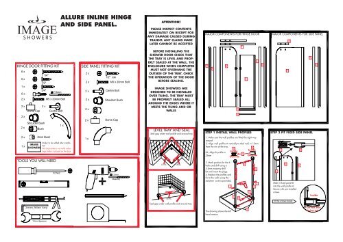
<strong>ALLURE</strong> <strong>INLINE</strong> <strong>HINGE</strong><br />
<strong>AND</strong> <strong>SIDE</strong> <strong>PANEL</strong>.<br />
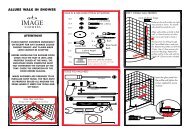
ATTENTION!<br />
PLEASE INSPECT CONTENTS<br />
IMMEDIATELY ON RECEIPT FOR<br />
ANY DAMAGE CAUSED DURING<br />
TRANSIT. ANY CLAIMS MADE<br />
LATER CANNOT BE ACCEPTED<br />
MAJOR COMPONENTS FOR <strong>HINGE</strong> DOOR<br />
MAJOR COMPONENTS FOR <strong>SIDE</strong> <strong>PANEL</strong><br />
<strong>HINGE</strong> DOOR FITTING KIT<br />
<strong>SIDE</strong> <strong>PANEL</strong> FITTING KIT<br />
BEFORE INSTALLING THE<br />
SHOWER DOOR CHECK THAT<br />
THE TRAY IS LEVEL <strong>AND</strong> PROP-<br />
ERLY SEALED AT THE WALL. THE<br />
ENCLOSURE WHEN COMPLETED<br />
MUST NOT OVERHANG THE<br />
OUT<strong>SIDE</strong> OF THE TRAY. CHECK<br />
THE OPERATION OF THE DOOR<br />
BEFORE SEALING.<br />
IMAGE SHOWERS ARE<br />
DESIGNED TO BE INSTALLED<br />
OVER TILING. THE TRAY MUST<br />
BE PROPERLY SEALED ALL<br />
AROUND THE EDGES WHERE IT<br />
MEETS THE TILING <strong>AND</strong> OR<br />
WALLS<br />
LEVEL TRAY <strong>AND</strong> SEAL<br />
Seal gap under wall profile and around tray<br />
STEP 1 INSTALL WALL PROFILES<br />
STEP 2 FIT FIXED <strong>SIDE</strong> <strong>PANEL</strong><br />
Sticker to be added after installation<br />
IMAGE<br />
SHOWERS N.B Guarantee is not valid unless<br />
logo sticker is placed on the door.<br />
1. Make sure the wall profiles are fitted the right way<br />
around.<br />
2. Align wall profiles A vertically to tiled wall, in 15mm<br />
from the rim of the tray.<br />
2A. Align B profile in<br />
52mm<br />
Inside<br />
Outside<br />
Inside<br />
Outside<br />
TOOLS YOU WILL NEED<br />
3. Mark position for the 6<br />
holes and drill using a<br />
5.5mm masonry drill<br />
bit.and insert the plugs.<br />
4. Replace the profiles and<br />
fix to the walls using the<br />
6x32mm screws provided.<br />
Slide in fixed panel D<br />
into the wall profile A<br />
Secure with pre-installed<br />
screws<br />
Inside<br />
Fit the screws loosly<br />
Seal gap under wall profile and around tray<br />
The drawing shows the left<br />
hand version.<br />
Curved Side<br />
facing out
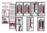
STEP 3 FIT TOP RAIL TO FIXED <strong>PANEL</strong><br />
To fit the top rail insert centrebolt into<br />
shoulderbush and then insert into glass<br />
from outside and fit through bush on<br />
inside. Fit top rail onto centre bolts and fix<br />
with 2XM5X20mm bolts using allen key<br />
and 17mm spanner. Twist on dome caps.<br />
Glass<br />
*The niche fitting profile is the longer of the two profiles<br />
(-30mm)*<br />
STEP 4 FIT NICHE FITTING PROFILE STEP 5 FIT MOVING <strong>PANEL</strong> STEP 6 FIT H<strong>AND</strong>LE<br />
Top Rail<br />
Pre drilled hole.<br />
In Nylon Bracket<br />
Put niche profile<br />
into wall profile<br />
and fix to the top<br />
rail by drilling,<br />
using the 2.8mm<br />
drill bit and<br />
fix with the 3/4”<br />
CSK screw<br />
through the pre<br />
drilled hole.<br />
Niche profile<br />
Fit hinge on door panel E onto hinge on<br />
the fixed panel D as shown. The hinge<br />
on the door panel is positioned above<br />
the hinge on the fixed panel. It slots into<br />
it and sits there<br />
Inside<br />
Glass<br />
8mm<br />
Bush<br />
Outside<br />
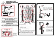
STEP 7 ALLIGN <strong>AND</strong> FIX PROFILE<br />
Ensure moving panel is parallel with the<br />
tray and that the magnets are sealing<br />
fully. then fix profiles using 2.8mm drillbit<br />
and the 5 x 1/2” CSK screws. Make sure<br />
the fixed panel is also secure using the 4<br />
clamps.<br />
STEP 8 FIT DEFLECTOR STRIP<br />
Drip delfector<br />
will bend<br />
slightly to<br />
fit<br />
Guide Block<br />
Put bead of silicone into slot on the back<br />
of drip deflector profile H as shown.<br />
Slot drip deflector profile H into position<br />
on the tray across the opening between<br />
the fixed panel D and niche profile C.<br />
Make sure that each end of the drip<br />
deflector is fitted into the guide block as<br />
shown<br />
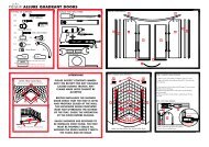
<strong>ALLURE</strong> <strong>INLINE</strong> <strong>HINGE</strong> DOOR WITH <strong>SIDE</strong> <strong>PANEL</strong><br />
STEP 9 FINAL ADJUSTMENTS & SEALING<br />
STEP 1 INSTALL WALL PROFILES<br />
STEP 1 INSTALL WALL PROFILES<br />
STEP 4 INSTALL CORNER JOINT<br />
STEP 5 & 6 AS NICHE FITTING<br />
Inside of shower<br />
Outside of shower<br />
Clip screw<br />
cover strip onto<br />
both wall<br />
profiles.<br />
Inside<br />
Outside<br />
Inside<br />
Outside<br />
1. Make sure profiles are turned the right<br />
way round.<br />
2. Allign wall profiles A & A vertically to<br />
tiles wall keeping both profiles 15mm from<br />
edge of tray.<br />
STEP 7 ALLIGN & TIGHTEN PROFILES<br />
3. Mark the position of the holes and drill<br />
using a 5.5mm masonry drill bit.<br />
4. Insert plugs and fix the profiles to the<br />
wall using the 6 x 32mm screws.<br />
Add cover caps N and O<br />
as shown and trim to size<br />
required<br />
STEP 2 FIT FIXED <strong>PANEL</strong>S AS NICHE<br />
FITTING.<br />
Ensure moving panel as parallel with the<br />
tray and that magnets are sealing fully.<br />
When adjusting correctly tighten clamps.<br />
Seal outside bottom<br />
as shown in red and<br />
inside of shower as<br />
shown in red.<br />
STEP 3 FIT TOP RAILS TO FIXED<br />
<strong>PANEL</strong>S AS NICHE FITTING<br />
Slide the larger upper corner joint K<br />
between the two main frames D and D1 as<br />
shown. Use the two 1/2” CSK screws to fit<br />
the joint.<br />
STEP 8 & 9 AS NICHE FITTING