ALLURE WALK IN SHOWER - Image Showers
ALLURE WALK IN SHOWER - Image Showers
ALLURE WALK IN SHOWER - Image Showers

You also want an ePaper? Increase the reach of your titles
YUMPU automatically turns print PDFs into web optimized ePapers that Google loves.
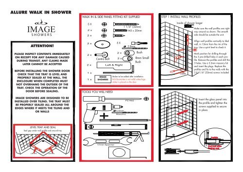
<strong>ALLURE</strong> <strong>WALK</strong> <strong>IN</strong> <strong>SHOWER</strong><br />
<strong>WALK</strong> <strong>IN</strong> & SIDE PANEL FITT<strong>IN</strong>G KIT SUPPLIED<br />
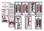
STEP 1 <strong>IN</strong>STALL WALL PROFILES<br />
5 X<br />
1 1/4” (32mm)<br />
M5 x 20mm<br />
Inside of shower longer<br />
Make sure the wall profiles are right<br />
way around as shown. The smooth<br />
side should be outside the unit.<br />
ATTENTION!<br />
5 X<br />
2.8mm<br />
Allign wall profiles vertically to tiled<br />
wall, in 15mm from the rim of the<br />
tray. Use a spirit level to check it.<br />
PLEASE <strong>IN</strong>SPECT CONTENTS IMMEDIATELY<br />
ON RECEIPT FOR ANY DAMAGE CAUSED<br />
DUR<strong>IN</strong>G TRANSIT. ANY CLAIMS MADE<br />
LATER CANNOT BE ACCEPTED<br />
BEFORE <strong>IN</strong>STALL<strong>IN</strong>G THE <strong>SHOWER</strong> DOOR<br />
CHECK THAT THE TRAY IS LEVEL AND<br />
PROPERLY SEALED AT THE WALL. THE<br />
ENCLOSURE WHEN COMPLETED MUST<br />
NOT OVERHANG THE OUTSIDE OF THE<br />
TRAY. CHECK THE OPERATION OF THE<br />
DOOR BEFORE SEAL<strong>IN</strong>G.<br />
IMAGE <strong>SHOWER</strong>S ARE DESIGNED TO BE<br />
<strong>IN</strong>STALLED OVER TIL<strong>IN</strong>G. THE TRAY MUST<br />
BE PROPERLY SEALED ALL AROUND THE<br />
EDGES WHERE IT MEETS THE TIL<strong>IN</strong>G AND<br />
OR WALLS<br />
Centre Bolt<br />
IMAGE<br />
<strong>SHOWER</strong>S<br />
TOOLS YOU WILL NEED<br />
Bush<br />
8mm Small<br />
Bush<br />
Sticker to be added after installation<br />
N.B Guarantee is not valid unless logo<br />
sticker is placed on the door.<br />
Mark position for drilling through<br />
the 3 pre-drilled holes in each profile.<br />
Remove the profiles and drill the<br />
3 holes. Use a 5.5mm masonry bit<br />
and insert the plugs. Replace the<br />
profiles and fix to the walls with the<br />
3 X 11/4” (32mm) screws included<br />
Insert the glass panel into<br />
the profile and tighten the<br />
screws supplied to secure<br />
in place.<br />
LEVEL TRAY AND SEAL<br />
Seal gap under wall profile and around tray
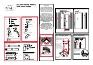
STEP 2 <strong>IN</strong>STALL MA<strong>IN</strong> PANEL<br />
Outside<br />
Inside<br />
Support rail, fix<br />
and screw into<br />
place.<br />
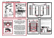
STEP 3 <strong>IN</strong>STALL SIDE PANEL<br />
To Install the support<br />
rail to the fixed panel<br />
insert J4 into J1 and<br />
then insert into glass<br />
from the outside of the<br />
fixed panel.<br />
Then insert bush J2<br />
into bolt J4 from<br />
inside of glass. Fit<br />
support rail to centre<br />
bolt on the inside of<br />
the glass. On each<br />
side using the M5 x<br />
20mm bolts J3 screw<br />
on dome cap J5 to<br />
complete<br />
Receiver bracket,<br />
mark and drill<br />
Put wall bracket in end of rail(it may<br />
be necessary to remve rail from<br />
glass). Position rail and bracket level<br />
against wall. Remove<br />
rail from bracket and<br />
mark. Drill two holes<br />
with 5.5 masonry<br />
bit. Insert lugs and<br />
screw in bracket with<br />
32mm screws, then<br />
re-assemble support<br />
rail to glass and into<br />
bracket. Then drill<br />
through pre-drilled<br />
holes with 2.8bit and<br />
secure with 2 X<br />
13mm screws<br />
Install the side<br />
panel profile<br />
ensuring that it is<br />
level<br />
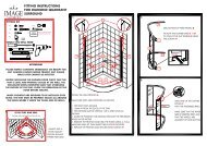
STEP 4 <strong>IN</strong>STALL SUPPORT ARM<br />
STEP 5 SEAL<strong>IN</strong>G<br />
Make sure bottom of wall profile is sealed between<br />
the tray and wall<br />
Use 10mm masonry<br />
bit to fit arm to wall<br />
and line up bracket<br />
on top of glass and<br />
tighten nylon screws<br />
Seal full height of<br />
wall profiles on<br />
inside<br />
Tighten the two nylon screws<br />
to the glass.<br />
Seal on outside