A Hermetic Seal Using Composite Thin Film In/Sn Solder as an ...
A Hermetic Seal Using Composite Thin Film In/Sn Solder as an ...
A Hermetic Seal Using Composite Thin Film In/Sn Solder as an ...

Create successful ePaper yourself
Turn your PDF publications into a flip-book with our unique Google optimized e-Paper software.
Copyright © 2009 Year IEEE. Reprinted from Journal of ELECTRONIC<br />
MATERIALS. Such permission of the IEEE does not in <strong>an</strong>y way imply IEEE<br />
endorsement of <strong>an</strong>y of <strong>In</strong>stitute of Microelectronics’ products or services. <strong>In</strong>ternal of<br />
personal use of this material is permitted. However, permission to reprint/republish this<br />
material for advertising or promotional purposes or for creating new collective works for<br />
resale or redistribution must be obtained from the IEEE by writing to pubspermission@ieee.org.
Journal of ELECTRONIC MATERIALS, Vol. 38, No. 1, 2009<br />
DOI: 10.1007/s11664-008-0561-x<br />
Ó 2008 TMS<br />
Regular Issue Paper<br />
A <strong>Hermetic</strong> <strong>Seal</strong> <strong>Using</strong> <strong>Composite</strong> <strong>Thin</strong>-<strong>Film</strong> <strong>In</strong>/<strong>Sn</strong> <strong>Solder</strong><br />
<strong>as</strong> <strong>an</strong> <strong>In</strong>termediate Layer <strong>an</strong>d Its <strong>In</strong>terdiffusion Reaction with Cu<br />
LI-LING YAN, 1,3 CHENG-KUO LEE, 1,2,4 DA-QUAN YU, 1 AI-BIN YU, 1<br />
WON-KYOUNG CHOI, 1 JOHN-H LAU, 1 <strong>an</strong>d SEUNG-UK YOON 1<br />
1.—<strong>In</strong>stitute of Microelectronics, Agency for Science & Technology <strong>an</strong>d Research (A*STAR),<br />
11 Science Park II, Singapore 117685, Singapore. 2.—Department of Electrical <strong>an</strong>d Computer<br />
Engineering National University of Singapore, 4 Engineering Drive 3, Singapore 117576,<br />
Singapore. 3.—e-mail: y<strong>an</strong>ll@ime.a-star.edu.sg. 4.—e-mail: elelc@nus.edu.sg<br />
A bonding joint between Cu metallization <strong>an</strong>d evaporated <strong>In</strong>/<strong>Sn</strong> composite<br />
solder is produced at a temperature lower th<strong>an</strong> 200°C in air. The effects of<br />
bonding temperature <strong>an</strong>d duration on the interfacial bonding strength are<br />
studied herein. Cross sections of bonding joints processed at different bonding<br />
conditions were examined by sc<strong>an</strong>ning electron microscopy (SEM). The optimal<br />
condition, i.e., bonding temperature of 180°C for 20 min, w<strong>as</strong> chosen because it<br />
gave rise to the highest average bonding strength of 6.5 MPa, <strong>an</strong>d a uniform<br />
bonding interface with minimum voids or cracks. Good bond formation w<strong>as</strong> also<br />
evidenced by sc<strong>an</strong>ning acoustic imaging. For bonding couples of patterned dies,<br />
a helium leak rate of 5.8 9 10 -9 atm cc/s w<strong>as</strong> me<strong>as</strong>ured, indicating a hermetic<br />
seal. The interfacial reaction between Cu <strong>an</strong>d <strong>In</strong>/<strong>Sn</strong> w<strong>as</strong> also studied. <strong>In</strong>termetallic<br />
compounds (IMCs) such <strong>as</strong> Au<strong>In</strong> 2 ,Cu 6 <strong>Sn</strong> 5 , <strong>an</strong>d Cu 11 <strong>In</strong> 9 were detected<br />
by me<strong>an</strong>s of x-ray diffraction <strong>an</strong>alysis (XRD), <strong>an</strong>d tr<strong>an</strong>smission electron<br />
microscopy (TEM) accomp<strong>an</strong>ied by energy-dispersive x-ray (EDX) spectroscopy.<br />
Chemical composition <strong>an</strong>alysis also revealed that solder interlayers, <strong>Sn</strong>,<br />
<strong>an</strong>d <strong>In</strong> were completely converted into IMCs by reaction with Cu. All the IMCs<br />
formed in the joints have remelting temperatures above 300°C according to the<br />
Cu-<strong>In</strong>, Cu-<strong>Sn</strong>, <strong>an</strong>d Au-<strong>In</strong> ph<strong>as</strong>e diagrams. Therefore, the joint is able to sustain<br />
high service temperatures due to the presence of these IMCs.<br />
Key words: <strong>In</strong>/<strong>Sn</strong> solder, low-temperature bonding, interfacial reaction,<br />
intermetallic compounds, copper<br />
INTRODUCTION<br />
<strong>Hermetic</strong> seals are required for m<strong>an</strong>y micro-electromech<strong>an</strong>ical<br />
system (MEMS) <strong>an</strong>d optoelectronics<br />
devices, which must be impervious to external<br />
influences such <strong>as</strong> moisture <strong>an</strong>d air. Conventional<br />
hermetic wafer bonding technologies such <strong>as</strong> fusion<br />
bonding, <strong>an</strong>odic bonding, Au-<strong>Sn</strong> eutectic soldering,<br />
Cu-Cu bonding, <strong>an</strong>d frit gl<strong>as</strong>s bonding c<strong>an</strong> only be<br />
conducted at processing temperatures above<br />
250°C. 1 However, a low-temperature bonding process<br />
is desirable for a hermetic seal to reduce the<br />
(Received April 6, 2008; accepted September 2, 2008;<br />
published online October 16, 2008)<br />
thermally induced warpage in these devices. An<br />
<strong>In</strong>-<strong>Sn</strong>-b<strong>as</strong>ed alloy is a very attractive lead-free solder<br />
material for a bonding joint due to its low<br />
melting temperature (
A <strong>Hermetic</strong> <strong>Seal</strong> <strong>Using</strong> <strong>Composite</strong> <strong>Thin</strong>-<strong>Film</strong> <strong>In</strong>/<strong>Sn</strong> <strong>Solder</strong> <strong>as</strong> <strong>an</strong> <strong>In</strong>termediate Layer<br />
<strong>an</strong>d Its <strong>In</strong>terdiffusion Reaction with Cu<br />
201<br />
joining method that combines features of conventional<br />
soldering <strong>an</strong>d diffusion bonding processes.<br />
The bonding is produced when the substrate metal<br />
dissolves into the molten solder <strong>an</strong>d rapidly reacts<br />
to form intermetallic compounds (IMCs) with the<br />
solder materials. When the molten solder layer is<br />
s<strong>an</strong>dwiched between layers of substrate metals, the<br />
whole layer of molten solder may be consumed<br />
through the formation of high-melting IMCs. 9 Thus,<br />
the obtained bonding joint c<strong>an</strong> survive subsequent<br />
m<strong>an</strong>ufacturing operations that may involve higher<br />
temperatures.<br />
<strong>Thin</strong>-film solder <strong>In</strong> <strong>an</strong>d/or <strong>Sn</strong> <strong>as</strong> <strong>an</strong> intermediate<br />
bonding layer h<strong>as</strong> recently been used in lowtemperature<br />
wafer bonding for microelectronic<br />
packaging. 5–8 <strong>Hermetic</strong> packaging h<strong>as</strong> also been<br />
developed at temperatures <strong>as</strong> low <strong>as</strong> 150°C by using<br />
<strong>an</strong> <strong>In</strong>-<strong>Sn</strong> alloy. 8 However, no-one h<strong>as</strong> studied the<br />
interfacial reaction of thin-film solder with the<br />
substrate <strong>an</strong>d the remelting temperature of the final<br />
joint, which are very import<strong>an</strong>t in m<strong>an</strong>ufacturing<br />
operations such <strong>as</strong> multiple reflows. With a highmelting<br />
seal, not only c<strong>an</strong> the sealed packages be<br />
engaged in subsequent soldering steps, but also<br />
joint creep resist<strong>an</strong>ce <strong>an</strong>d dimensional stability c<strong>an</strong><br />
be improved. M<strong>an</strong>y studies have been carried out on<br />
the characterization of the interfacial reaction<br />
between a Cu substrate <strong>an</strong>d bulk <strong>In</strong>-<strong>Sn</strong> alloy, 3,10–15<br />
where the eutectic solder <strong>In</strong>-48wt.%<strong>Sn</strong> is applied on<br />
the substrate either by dipping into a molten solder<br />
bath 3,10–12 or s<strong>an</strong>dwiching a solder foil. 10–12 However,<br />
the reaction between Cu <strong>an</strong>d bulk solder<br />
should be different from the thin-film c<strong>as</strong>e because<br />
in the latter c<strong>as</strong>e there is only a limited amount of<br />
solder material in contact with the substrate <strong>an</strong>d<br />
the chemical composition in the solder layers is<br />
inhomogeneous. 16<br />
<strong>In</strong> this work, low-temperature bonding b<strong>as</strong>ed on<br />
<strong>Sn</strong>/<strong>In</strong> composite solder h<strong>as</strong> been developed. Bonding<br />
quality is evaluated by me<strong>an</strong>s of pull testing, crosssection<br />
observation, acoustic imaging, <strong>an</strong>d helium<br />
leak rate testing. The interfacial reaction between<br />
Cu <strong>an</strong>d the composite solder w<strong>as</strong> studied by<br />
me<strong>an</strong>s of sc<strong>an</strong>ning electron microscopy (SEM),<br />
tr<strong>an</strong>smission electron microscopy (TEM) with energy-dispersive<br />
x-ray (EDX), <strong>an</strong>d x-ray diffraction<br />
<strong>an</strong>alysis (XRD).<br />
EXPERIMENTAL PROCEDURE<br />
Very thin layers of SiO 2 /Si 3 N 4 /Ti/Cu were evaporated<br />
sequentially on flat silicon wafers to enh<strong>an</strong>ce<br />
the adhesion of subsequent layers <strong>an</strong>d also to serve<br />
<strong>as</strong> a seed layer for the subsequent copper electroplating.<br />
Their thicknesses were 300 Å, 1500 Å,<br />
500 Å, <strong>an</strong>d 1000 Å, respectively. Then, a 3-lm copper<br />
layer w<strong>as</strong> electroplated on the top of the wafer.<br />
As the final step, a 1.6-lm indium layer followed by<br />
a 1.4-lm tin layer <strong>an</strong>d 50 nm of Au were deposited<br />
on Cu sequentially by evaporation. The thin layer of<br />
Au w<strong>as</strong> deposited on the <strong>Sn</strong> layer to inhibit oxygen<br />
penetration, which c<strong>an</strong> occur when the samples are<br />
removed from the evaporator vacuum chamber <strong>an</strong>d<br />
exposed to air. 3,4 This type of wafer is called b<strong>as</strong>e<br />
wafer 1; they are mainly used for all the described<br />
tests except helium leak rate testing. For the purpose<br />
of helium leak rate testing, <strong>an</strong>other type of<br />
wafer patterned with a bonding ring <strong>an</strong>d cavity w<strong>as</strong><br />
prepared. The bonding ring had a width of 300 lm<br />
<strong>an</strong>d a size of 8 mm 9 8 mm, while the cavity had a<br />
size of 6 mm 9 6 mm with a depth of 250 lm. This<br />
type of patterned wafer is called b<strong>as</strong>e wafer 2. On<br />
the bonding ring area, the multilayer materials<br />
were deposited in the same sequence <strong>an</strong>d with the<br />
same thickness <strong>as</strong> on b<strong>as</strong>e wafer 1.<br />
To perform the bonding, cap silicon wafers were<br />
prepared in the same way <strong>as</strong> the b<strong>as</strong>e wafers except<br />
without the <strong>In</strong>/<strong>Sn</strong>/Au layer on the electroplated Cu<br />
surface. Similarly, cap wafer 1 w<strong>as</strong> a flat silicon<br />
wafer, <strong>an</strong>d cap wafer 2 w<strong>as</strong> a ring patterned wafer.<br />
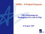
The bonding pair with the multilayer structure is<br />
shown schematically in Fig. 1.<br />
Both cap <strong>an</strong>d b<strong>as</strong>e wafers were then diced into<br />
small, 10 mm 9 10 mm dies. Before bonding, cap<br />
dies were first cle<strong>an</strong>ed with acetic acid to remove the<br />
copper oxide layer. Then the bonding couples, i.e.,<br />
cap dies with their corresponding b<strong>as</strong>e dies, were<br />
thermocompressed in air by using a flip-chip bonder<br />
(a)<br />
(b)<br />
Cap wafer 1<br />
Cap Si wafer<br />
SiO 2<br />
Si 3 N 4<br />
Ti<br />
Cu<br />
<strong>In</strong><br />
<strong>Sn</strong><br />
Au<br />
B<strong>as</strong>e wafer 1<br />
Cap wafer 2<br />
Bonding ring<br />
B<strong>as</strong>e Si wafer<br />
B<strong>as</strong>e wafer 2<br />
Fig. 1. (a) Schematic of bonding pairs for the flat wafer <strong>an</strong>d patterned wafer. (b) Multilayer material structure on cap wafer <strong>an</strong>d b<strong>as</strong>e wafer.
202<br />
Y<strong>an</strong>, Lee, D.-Q. Yu, A.-B. Yu, Choi, Lau, <strong>an</strong>d Yoon<br />
(SUSS FC 150). For dies from cap wafer 1 <strong>an</strong>d b<strong>as</strong>e<br />
wafer 1, i.e., flat dies, bonding w<strong>as</strong> carried out under<br />
various conditions. The applied bonding pressure for<br />
all the samples in this work w<strong>as</strong> 1.5 MPa, <strong>an</strong>d the<br />
bonding temperature r<strong>an</strong>ged from 140°C to 180°C,<br />
<strong>an</strong>d the duration from 5 min to 20 min. The optimal<br />
condition which gave the best joint w<strong>as</strong> used for the<br />
bonding of patterned dies. Rosin mildly activated<br />
flux (FLUXOT-84032, <strong>In</strong>dium Co., Utica, NY) w<strong>as</strong><br />
applied on the surface of b<strong>as</strong>e dies before bonding in<br />
order to facilitate soldering.<br />
Bonding couples were characterized by pull testing<br />
to evaluate the interfacial bonding strength.<br />
They were glued with a customized fixture <strong>an</strong>d<br />
mounted on <strong>an</strong> <strong>In</strong>stron tensile machine. The pull<br />
test w<strong>as</strong> preformed at a crosshead speed of 0.01 mm/s.<br />
The strength value w<strong>as</strong> averaged over five samples<br />
tested. The fractured surfaces after the pull tests<br />
were studied by SEM/EDX <strong>an</strong>d XRD using Cu Ka<br />
radiation. Cross sections for SEM study were prepared<br />
by grinding the specimens with SiC paper,<br />
<strong>an</strong>d polished with 1.0-lm <strong>an</strong>d 0.3-lm alumina<br />
powders. TEM/EDX examination w<strong>as</strong> also performed<br />
on the joint cross section. The thin foil<br />
preparation for TEM w<strong>as</strong> carried out following the<br />
procedure indicated in Ref. 17. Acoustic imaging by<br />
sc<strong>an</strong>ning acoustic microscopy (SAM) w<strong>as</strong> used for<br />
nondestructive study of the bond interface. The<br />
process involves launching ultr<strong>as</strong>onic waves into<br />
the samples at a frequency of 230 MHz using a<br />
piezoelectric tr<strong>an</strong>sducer. The same tr<strong>an</strong>sducer also<br />
acts <strong>as</strong> a receiver of the reflected waves from the<br />
sample. The hermeticity of the ring seals for the<br />
patterned dies w<strong>as</strong> evaluated by helium leak rate<br />
testing (MIL-STD-883).<br />
RESULTS AND DISCUSSION<br />
Effect of Bonding Conditions<br />
<strong>an</strong>d Cross-Section Observations<br />
The morphology of the contacted surfaces is very<br />
import<strong>an</strong>t for underst<strong>an</strong>ding the bonding process.<br />
The top surface of <strong>as</strong>-received b<strong>as</strong>e dies <strong>an</strong>d its cross<br />
section w<strong>as</strong> examined by SEM, <strong>as</strong> shown in Fig. 2.<br />
Both views show that the surface is extremely rough<br />
<strong>an</strong>d is featured with a gr<strong>an</strong>ular structure with a<br />
grain size of 2 lm to3lm. <strong>In</strong> order to bond surfaces<br />
with such rough features, a molten solder layer <strong>an</strong>d<br />
high pressure is necessary to fill the gaps between<br />
the surfaces.<br />
Figure 3 shows the pull test results of couples<br />
bonded under different conditions. The bonding<br />
duration <strong>an</strong>d temperature have signific<strong>an</strong>t effects<br />
on the bonding strength. Bonding at 140°C for<br />
5 min <strong>an</strong>d 20 min gave rise to a bonding strength<br />
of only 0.78 MPa <strong>an</strong>d 2.93 MPa, respectively.<br />
<strong>In</strong>cre<strong>as</strong>ing the temperature to 160°C led to a higher<br />
bonding strength of 3.6 MPa <strong>an</strong>d 4.8 MPa for the<br />
same two bonding durations, respectively. A further<br />
incre<strong>as</strong>e of temperature to 180°C produced <strong>an</strong><br />
average bonding strength of 6.5 MPa <strong>an</strong>d 3.2 MPa<br />
when bonded for 20 min <strong>an</strong>d 5 min, respectively.<br />
According to the pull test results, the optimal<br />
bonding condition, i.e., 180°C <strong>an</strong>d 20 min, w<strong>as</strong><br />
selected for the bonding of patterned dies.<br />
At a bonding temperature of 140°C, which is<br />
lower th<strong>an</strong> the melting point of <strong>In</strong>, i.e., 156°C, the <strong>In</strong><br />
layer c<strong>an</strong>not melt. The contacted surfaces are joined<br />
Bonding Strength (MPa)<br />
8<br />
7<br />
6<br />
5<br />
4<br />
3<br />
2<br />
1<br />
0<br />
5 minutes<br />
20 minutes<br />
140 150 160 170 180 190<br />
Temperature ( o C)<br />
Fig. 3. Effect of bonding conditions with various temperatures <strong>an</strong>d<br />
durations on bonding strength.<br />
Fig. 2. SEM images of <strong>as</strong>-received evaporated composite coating surface: (a) top view <strong>an</strong>d (b) cross section.
A <strong>Hermetic</strong> <strong>Seal</strong> <strong>Using</strong> <strong>Composite</strong> <strong>Thin</strong>-<strong>Film</strong> <strong>In</strong>/<strong>Sn</strong> <strong>Solder</strong> <strong>as</strong> <strong>an</strong> <strong>In</strong>termediate Layer<br />
<strong>an</strong>d Its <strong>In</strong>terdiffusion Reaction with Cu<br />
203<br />
Fig. 4. Cross sections of bonding couples obtained at different bonding conditions (a) 140°C, 5 min; (b) 140°C, 20 min; (c) 160°C, 5 min; (d)<br />
160°C, 20 min; (e) 180°C, 5 min; <strong>an</strong>d (f) 180°C, 20 min.<br />
together only by deformation due to the applied<br />
pressure, but the <strong>as</strong>perities on the rough surfaces<br />
c<strong>an</strong>not be compensated, <strong>as</strong> is evident from the wide<br />
gap present along the interface, <strong>as</strong> shown in Fig. 4a<br />
<strong>an</strong>d b. A longer bonding time facilitates greater<br />
surface deformation <strong>an</strong>d causes better contact <strong>an</strong>d<br />
shows less gaps. As a result, the bonding strength is<br />
higher th<strong>an</strong> that bonded for 5 min. A similar<br />
observation w<strong>as</strong> made for joints produced at 160°C,<br />
<strong>as</strong> shown in Fig. 4c <strong>an</strong>d d. The bonding interface<br />
still leaves large gaps, although this improved when<br />
bonded for a longer time. This is because the temperature<br />
of 160°C is only slightly higher th<strong>an</strong> the<br />
melting point of <strong>In</strong>, so the solder layer is only partially<br />
melted <strong>an</strong>d c<strong>an</strong>not fill the large gaps.<br />
<strong>In</strong> contr<strong>as</strong>t, the joints produced at 180°C showed<br />
much less voids or even a void-free contact, <strong>as</strong><br />
shown in Fig. 4e <strong>an</strong>d f. The thickness of the joint is<br />
uniform throughout the whole contact area with a<br />
typical value of 6.2 ± 0.5 lm. The bond couples are<br />
in good contact <strong>an</strong>d no interface line is observed,<br />
which me<strong>an</strong>s that the intermediate solder layers<br />
melted during the bonding process <strong>an</strong>d leveled off<br />
the troughs between grains.<br />
SEM microscopy <strong>an</strong>d EDX composition mapping<br />
of the fractured surface after pull testing display a<br />
combined cohesive <strong>an</strong>d adhesive failure mode, <strong>as</strong><br />
shown in Fig. 5. The surface shown is that of a cap<br />
die separated from its bond couple at a bonding<br />
strength of 7.3 MPa, which is a relatively high value<br />
among the tested samples. The flat regions seen in<br />
Fig. 5a represent adhesive failure of the Cu/IMC<br />
interface where the element mapping reveals Cu <strong>as</strong><br />
the domin<strong>an</strong>t element, where<strong>as</strong> the other regions<br />
represent cohesive failure within IMCs, <strong>as</strong> the elements<br />
Cu, <strong>In</strong>, <strong>an</strong>d <strong>Sn</strong> are evenly distributed without<br />
clustering. This mixed failure mode suggests that<br />
the adhesion of the solder layer <strong>an</strong>d Cu is very good<br />
due to their interfacial reaction.<br />
<strong>Seal</strong>ing Quality Assessment<br />
SAM is a popular tool for monitoring bonding<br />
interfaces. During acoustic imaging the reflection<br />
intensity of the ultr<strong>as</strong>ound waves is captured<br />
through the bond interface. Ultr<strong>as</strong>ound waves are<br />
reflected when they encounter a material discontinuity,<br />
such <strong>as</strong> voids, <strong>an</strong>d are displayed with white<br />
pixels in images. Otherwise they have low reflection<br />
when they p<strong>as</strong>s through are<strong>as</strong> of material continuum,<br />
which indicates good bond formation, signified<br />
by dark pixels in the images. The acoustic images of<br />
the bond interface for flat dies <strong>an</strong>d patterned dies<br />
bonded at 180°C for 20 min are shown in Fig. 6a<br />
<strong>an</strong>d b, respectively. A uniform bond with minimum<br />
void formation is observed. Especially for the patterned<br />
dies, the whole bonding ring is a uniform<br />
gray color, indicating that the bonded couple h<strong>as</strong><br />
intimate contact, <strong>an</strong>d that no voids or delamination<br />
occurred. The helium leak rate test showed that<br />
the bonding couples of the patterned dies were<br />
hermetic seals with <strong>an</strong> average leak rate value of
204<br />
Y<strong>an</strong>, Lee, D.-Q. Yu, A.-B. Yu, Choi, Lau, <strong>an</strong>d Yoon<br />
Fig. 5. Fracture surface examination after pull testing. (a) SEM photography <strong>an</strong>d EDX element mapping: (b) Cu, (c) <strong>In</strong>, <strong>an</strong>d (d) <strong>Sn</strong>.<br />
Fig. 6. Acoustic images of (a) a well-bonded flat silicon dice, (b) a well-bonded patterned dice at 180°C for 20 min, <strong>an</strong>d (c) a poorly bond<br />
interface formed at 140°C for 20 min.<br />
5.8 9 10 -9 atm cc/s (five tested samples). For<br />
comparison, a poor bond interface formed at 140°C<br />
for 20 min, exhibiting voids or delamination <strong>as</strong><br />
white pixels, is shown in Fig. 6c. These poorly<br />
bonded samples were either separate on helium<br />
leak rate test or exhibited a leak rate on the order of<br />
10 -8 atm cc/s.<br />
Cu/<strong>In</strong>/<strong>Sn</strong>/Cu <strong>In</strong>terfacial Reaction<br />
For the interfacial reaction study, all the studied<br />
samples were bonded at a temperature of 180°C for<br />
20 min. The fractured surfaces after the pull test<br />
were studied by XRD to examine the IMCs that had<br />
evolved in the bonding reaction zone. Au<strong>In</strong> 2 ,<br />
Cu 6 <strong>Sn</strong> 5 , <strong>an</strong>d Cu 11 <strong>In</strong> 9 ph<strong>as</strong>es were found on XRD<br />
<strong>an</strong>alysis, <strong>as</strong> shown in Fig. 7. No <strong>Sn</strong> or <strong>In</strong> peak w<strong>as</strong><br />
detected.<br />
Since the IMC layers are relatively thin, the TEM<br />
technique w<strong>as</strong> chosen <strong>as</strong> it provides local chemical<br />
<strong>an</strong>alysis. Figure 8 shows TEM images of the region<br />
close to the b<strong>as</strong>e material silicon <strong>an</strong>d interfacial<br />
reaction region between Cu <strong>an</strong>d solder intermediate<br />
layers. It is seen from Fig. 8a that, on the top of the<br />
silicon, the first layer is silicon oxide, followed by<br />
silicon nitride, tit<strong>an</strong>ium, <strong>an</strong>d copper. The interfaces<br />
between each layer are void free <strong>an</strong>d uniform.<br />
The silicon oxide <strong>an</strong>d nitride layers provide good
A <strong>Hermetic</strong> <strong>Seal</strong> <strong>Using</strong> <strong>Composite</strong> <strong>Thin</strong>-<strong>Film</strong> <strong>In</strong>/<strong>Sn</strong> <strong>Solder</strong> <strong>as</strong> <strong>an</strong> <strong>In</strong>termediate Layer<br />
<strong>an</strong>d Its <strong>In</strong>terdiffusion Reaction with Cu<br />
205<br />
800<br />
700<br />
⊕ Cu 6<br />
<strong>Sn</strong> 5<br />
600<br />
500<br />
∆<br />
⊗ Au<strong>In</strong> 2<br />
<strong>In</strong>tensity<br />
400<br />
300<br />
⊗<br />
200<br />
100<br />
0<br />
∆<br />
∆<br />
⊕<br />
∆<br />
∆<br />
∆<br />
⊕<br />
⊗<br />
∆<br />
⊕<br />
⊗<br />
⊕<br />
⊗<br />
⊕<br />
∆<br />
⊕<br />
∆<br />
∆ Cu 11<br />
<strong>In</strong> 9<br />
85<br />
⊕<br />
⊗<br />
∆<br />
⊕<br />
⊗<br />
⊕<br />
⊗<br />
⊗<br />
25 30 35 40 45 50 55 60 65 70 75 80 90<br />
2 θ<br />
Fig. 7. XRD results of the fracture surface after pull testing of samples bonded at 180°C for 20 min.<br />
Fig. 8. TEM images showing the bonding interface (a) in the silicon region <strong>an</strong>d (b) at the interface region.<br />
adhesion layers between the subsequent metal layer<br />
<strong>an</strong>d silicon b<strong>as</strong>e.<br />
Figure 8b shows the reaction zone between Cu<br />
<strong>an</strong>d the <strong>In</strong>/<strong>Sn</strong> solder interlayer. Small grains are<br />
clearly visible in the reaction zone. The elemental<br />
composition results of the selected points are summarized<br />
in Table I. Two IMCs c<strong>an</strong> be identified<br />
along the main reaction zone, i.e., Cu 6 (<strong>Sn</strong>,<strong>In</strong>) 5 <strong>an</strong>d<br />
Cu 11 (<strong>In</strong>,<strong>Sn</strong>) 9 . This result is consistent with the XRD<br />
results, which confirmed the presence of these two<br />
IMCs in the bonding interface. The composition of<br />
Cu reduced gradually from 56 at.% to 48 at.% from<br />
the near-Cu to the near-<strong>In</strong> region. EDX <strong>an</strong>alysis<br />
suggested that unreacted Cu remained that w<strong>as</strong> not<br />
used for joint formation. At the edge of the bonding<br />
interface the Cu composition drops dramatically<br />
<strong>an</strong>d only <strong>In</strong> <strong>an</strong>d Au dominate with the composition<br />
shown <strong>as</strong> points 11 <strong>an</strong>d 12 in Table I, i.e.,<br />
Cu 5.9 Au 34.0 <strong>In</strong> 59.0 <strong>Sn</strong> 1.1 <strong>an</strong>d Cu 5.1 Au 33 <strong>In</strong> 60.2 <strong>Sn</strong> 1.7 ,<br />
Table I. Summary of Point EDX Analysis Along<br />
the <strong>In</strong>terface Shown in the TEM Image<br />
Point<br />
Composition (at.%)<br />
Cu <strong>In</strong> <strong>Sn</strong> Au<br />
Equilibrium<br />
Ph<strong>as</strong>e<br />
1 99.5 0.3 0.2 0 Cu<br />
2 99.0 0.3 0.2 0.5 Cu<br />
3 56.0 28.5 15.5 0 Cu 11 (<strong>In</strong>,<strong>Sn</strong>) 9<br />
4 54.6 31.3 13.7 0.4 Cu 11 (<strong>In</strong>,<strong>Sn</strong>) 9<br />
5 52.1 30.4 17.0 0.5 Cu 11 (<strong>In</strong>,<strong>Sn</strong>) 9<br />
6 51.4 28.3 19.6 0.7 Cu 11 (<strong>In</strong>,<strong>Sn</strong>) 9<br />
7 50.2 31.2 18.3 0.3 Cu 11 (<strong>In</strong>,<strong>Sn</strong>) 9<br />
8 48.1 21.0 30.4 0.5 g-Cu 6 (<strong>Sn</strong>,<strong>In</strong>) 5<br />
9 49.8 23.4 26.6 0.2 g-Cu 6 (<strong>Sn</strong>,<strong>In</strong>) 5<br />
10 50.3 20.7 29.0 0 g-Cu 6 (<strong>Sn</strong>,<strong>In</strong>) 5<br />
11 5.9 59.0 1.1 34.0 Au(<strong>In</strong>,<strong>Sn</strong>) 2<br />
12 5.1 60.2 1.7 33.0 Au(<strong>In</strong>,<strong>Sn</strong>) 2
206<br />
Y<strong>an</strong>, Lee, D.-Q. Yu, A.-B. Yu, Choi, Lau, <strong>an</strong>d Yoon<br />
which corresponds to <strong>an</strong> equilibrium ph<strong>as</strong>e Au<strong>In</strong> 2 .<br />
<strong>In</strong> the soldering process, while the composite solder<br />
layers are in a liquid state, <strong>In</strong> <strong>an</strong>d <strong>Sn</strong> compete to<br />
react with Au. Although Au<strong>Sn</strong> 4 is commonly formed<br />
at the interface between Au <strong>an</strong>d <strong>Sn</strong> in some other<br />
systems at temperature
A <strong>Hermetic</strong> <strong>Seal</strong> <strong>Using</strong> <strong>Composite</strong> <strong>Thin</strong>-<strong>Film</strong> <strong>In</strong>/<strong>Sn</strong> <strong>Solder</strong> <strong>as</strong> <strong>an</strong> <strong>In</strong>termediate Layer<br />
<strong>an</strong>d Its <strong>In</strong>terdiffusion Reaction with Cu<br />
207<br />
4. S.W. Chen, S.K. Lin, <strong>an</strong>d C.F. Y<strong>an</strong>g, J. Electron. Mater. 35,<br />
72 (2006). doi:10.1007/s11664-006-0186-x.<br />
5. T.H. Chu<strong>an</strong>g, H.J. Lin, <strong>an</strong>d C.W. Tsao, J. Electron. Mater.<br />
35, 1566 (2006). doi:10.1007/s11664-006-0150-9.<br />
6. C.C. Lee <strong>an</strong>d S. Choe, Mater. Sci. Eng. A333, 45 (2002).<br />
7. R.W. Chu<strong>an</strong>g <strong>an</strong>d C.C. Lee, <strong>Thin</strong> Solid <strong>Film</strong>s 414, 175<br />
(2002). doi:10.1016/S0040-6090(02)00424-8.<br />
8. C. Lee, W.F. Hu<strong>an</strong>g, <strong>an</strong>d J.S. Shie, Sens. Actuators 85, 330<br />
(2000). doi:10.1016/S0924-4247(00)00338-1.<br />
9. G. Humpston <strong>an</strong>d D.M. Jacobson, Principles of <strong>Solder</strong>ing<br />
<strong>an</strong>d Brazing (ASM <strong>In</strong>ternational: Materials Park, 1993),<br />
p. 128.<br />
10. D.R. Frear <strong>an</strong>d P.T. Vi<strong>an</strong>co, Metall. Mater. Tr<strong>an</strong>s. A 25,<br />
1509 (1994). doi:10.1007/BF02665483.<br />
11. J.W. Morris Jr., J.L. Free Goldstein, <strong>an</strong>d Z. Mei, JOM 45, 25<br />
(1993).<br />
12. Z. Mei <strong>an</strong>d J.W. Morris Jr., J. Electron. Mater. 21, 401<br />
(1992). doi:10.1007/BF02660403.<br />
13. T.H. Chu<strong>an</strong>g, C.L. Yu, S.Y. Ch<strong>an</strong>g, <strong>an</strong>d S.S. W<strong>an</strong>g,<br />
J. Electron. Mater. 31, 640 (2002). doi:10.1007/s11664-<br />
002-0136-1.<br />
14. S. Sommadossi <strong>an</strong>d A.F. Guillermet, <strong>In</strong>termetallics 15, 912<br />
(2007). doi:10.1016/j.intermet.2006.10.050.<br />
15. D.G. Kim <strong>an</strong>d S.B. Jung, J. Alloy. Comp. 386, 151 (2005).<br />
doi:10.1016/j.jallcom.2004.05.055.<br />
16. K.N. Tu, Mater. Chem. Phys. 46, 217 (1996). doi:10.1016/<br />
S0254-0584(97)80016-8.<br />
17. S. Sommadossi, L. Litynska, P. Zieba, W. Gust, <strong>an</strong>d<br />
E.J. Mittemeijier, Mater. Chem. Phys. 81, 566 (2003).<br />
doi:10.1016/S0254-0584(03)00076-2.<br />
18. T.K. Lee, S. Zh<strong>an</strong>g, C.C. Wong, A.C. T<strong>an</strong>, <strong>an</strong>d D. Hadikusuma,<br />
<strong>Thin</strong> Solid <strong>Film</strong>s 504, 441 (2006). doi:10.1016/j.tsf.2005.<br />
09.112.<br />
19. L.Y. Hsiao, G.Y. J<strong>an</strong>g, K.J. W<strong>an</strong>g, <strong>an</strong>d J.G. Duh, J. Electron.<br />
Mater. 36, 1476 (2007). doi:10.1007/s11664-007-0282-6.<br />
20. S.W. Chen <strong>an</strong>d Y.W. Yen, J. Electron. Mater. 30, 1133<br />
(2001). doi:10.1007/s11664-001-0140-x.<br />
21. J.M. Koo <strong>an</strong>d S.B. Jung, J. Electron. Mater. 34, 1565 (2005).<br />
doi:10.1007/s11664-005-0166-6.<br />
22. T.H. Chu<strong>an</strong>g, S.Y. Ch<strong>an</strong>g, L.C. Tsao, W.P. Weng, <strong>an</strong>d H.M.<br />
Wu, J. Electron. Mater. 32, 195 (2003). doi:10.1007/s11664-<br />
003-0193-0.<br />
23. Y.M. Liu <strong>an</strong>d T.H. Chu<strong>an</strong>g, J. Electron. Mater. 29, 405<br />
(2000). doi:10.1007/s11664-000-0152-y.<br />
24. I. Shohji, S. Fujiwara, S. Kiyono, <strong>an</strong>d F. Kobay<strong>as</strong>hi, Scr.<br />
Mater. 40, 815 (1999). doi:10.1016/S1359-6462(99)00007-X.<br />
25. W.K. Choi, D.Q. Yu, C. Lee, L.L. Y<strong>an</strong>, A.B. Yu, S.U. Yoon,<br />
J.H. Lau, G.C. Moon, H.J. Yoon, <strong>an</strong>d M.L. Hyuck, Proceedings<br />
of 58th Electronic Components <strong>an</strong>d Technology Conference<br />
(Lake Buena Vista, Florida, 2008), p. 1294.