The current ATHENA brochure (PDF) - CAD-PLAN Gmbh
The current ATHENA brochure (PDF) - CAD-PLAN Gmbh
The current ATHENA brochure (PDF) - CAD-PLAN Gmbh

Create successful ePaper yourself
Turn your PDF publications into a flip-book with our unique Google optimized e-Paper software.
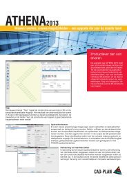
<strong>ATHENA</strong>2013<br />
<strong>The</strong> Auto<strong>CAD</strong> application for curtain wall design and façade engineering
Ideal for international design:<br />
<strong>ATHENA</strong> labels all the customer<br />
objects fully automatically and<br />
is able to translate a drawing into<br />
each of the eleven languages<br />
<strong>current</strong>ly contained in <strong>ATHENA</strong><br />
on the press of a key.<br />
<strong>The</strong>re are two key ingredients necessary to design impressive<br />
façades that function well. <strong>The</strong> first ingredient is a capable<br />
designer with experience and a knack for technically ingenious<br />
solutions. <strong>The</strong> second is a powerful <strong>CAD</strong> application that is<br />
precisely tailored to the designer’s requirement and provides<br />
the support for professional, error free designs that require<br />
less work and are delivered on time.<br />
This is where we call upon our Auto<strong>CAD</strong> application,<br />
<strong>ATHENA</strong>, the all-round software solution for design in<br />
• metal and facade construction<br />
• curtain wall and shopfront construction<br />
• glass construction<br />
• industrial construction<br />
• lightweight steel construction.<br />
<strong>ATHENA</strong> is the leading <strong>CAD</strong> based design software<br />
for curtain wall design and façade engineering on<br />
the market—and not without reason. Our software<br />
has been subject to consistent on-going development<br />
for twenty-three years and is used in metal<br />
construction companies, design offices and<br />
universities—in eleven languages and more than<br />
thirty-eight countries.<br />
Matched exactly to our users' requirements,<br />
<strong>ATHENA</strong> is a complete software package, offering<br />
practically everything to simplify the daily design<br />
tasks that confront the designer:<br />
• A 2D drawing environment with practical routines<br />
and libraries for producing elevations,<br />
cross-sections and workshop drawings.<br />
• A versatile 3D design section with the possibility<br />
of producing parts lists and production drawings<br />
directly from the 3D design.<br />
• Powerful computational tools for structural<br />
analysis and building physics.<br />
• A sheet editing program for sheet design and<br />
development.<br />
In addition, <strong>ATHENA</strong> is independent from specific<br />
aluminum manufacturers’ systems and can be<br />
matched to individual needs.
Four-way versatility!<br />
<strong>ATHENA</strong> contains four functional groups covering<br />
a range of performance for which you would have<br />
to procure four different programs.<br />
Functional Group 1: 2D design<br />
2D drawing functions are tuned for the rapid<br />
production of section and elevation drawings,<br />
plan views and production drawings. Features<br />
particularly promoting productivity include<br />
routines for semi-finished items, membranes,<br />
thermal insulation, panels or welded seams plus<br />
a comprehensive standard parts library with<br />
82,000 parts or the tools for managing materials,<br />
layers and blocks. A special advantage is that<br />
all <strong>ATHENA</strong> objects are intelligent ARX objects<br />
and can be edited with a double click!<br />
Functional Group 2: 3D design<br />
<strong>The</strong> 3D design is used for the free planning of<br />
complicated geometries, such as, sloping polygon<br />
façades, pyramids, glazed roofs and bays.<br />
To achieve this, profiles or profile groups are<br />
placed over the axes of a wire model. Cut parts<br />
can be automatically computed and the components<br />
(e.g. profiles) are output with the cut parts<br />
in a parts list or in a drawing. Dedicated master<br />
data can be created, containing the profile<br />
geometries, material properties, design rules or<br />
requirements from production. Based on this<br />
master data, as well as spatial elements you<br />
can design flat elements, such as windows and<br />
doors. <strong>The</strong> 3D design takes into account profile<br />
groups, cut parts, processes, sheet metal, glazing<br />
and also hardware. It can be displayed as<br />
a 3D view, 2D view and through any sections.<br />
<strong>The</strong> extracts can be output as parts lists or as<br />
production drawings. An interface to calculation<br />
programs and PPC/ERP is available.<br />
Functional Group 3: Sheet editing<br />
<strong>ATHENA</strong> now contains a complete sheet editing<br />
program for the quicker design of sheets with the<br />
associated developments. Increased productivity<br />
during sheet design comprises of clearly laid-out<br />
dialog boxes for the input of basic sheet data and<br />
processes, a 3D viewer for continuous visual<br />
checks and versatile options for the import and<br />
export of drawing data.<br />
Functional Group 4: Engineering<br />
Always on the safe side. <strong>ATHENA</strong>’s computational<br />
functions for structural analysis and building<br />
physics are well-developed tools for the exact<br />
determination of, for example, centers of gravity<br />
and moments, thermal resistances or sound<br />
insulation dimensions. You can conveniently<br />
compute the required moments of inertia or<br />
maximum deflections. You can also carry out<br />
thermal bridge analyses (isothermal calculations).<br />
In this way thermal bridges can be eliminated<br />
during the design stage.
Maximum<br />
efficiency for<br />
your plans<br />
and drawings<br />
2D DESIGN<br />
Classical two-dimensional construction<br />
takes up a particularly large<br />
part of the designer‘s workday<br />
routine—drawing views, generating<br />
cross-sections, drawing up detailed<br />
drawings, producing manufacturing<br />
documentation. <strong>The</strong> optimization of<br />
the work procedure with a special<br />
software solution leads to increased<br />
productivity and a higher-quality<br />
finished product. This is a big advantage<br />
for the designer who is no<br />
longer impeded by the limitations of<br />
the working tools and has a powerful<br />
assistant at his side to relieve much<br />
of the work.<br />
<strong>ATHENA</strong> has proven its capabilities<br />
over years and the 2D section especially<br />
profits from careful maintenance<br />
and on-going development.<br />
Screwed assembled joint<br />
<strong>ATHENA</strong> has a program for<br />
generating screwed assembled<br />
joints. Screwed joints<br />
consisting of a number of<br />
<strong>ATHENA</strong> parts (screw, washer,<br />
nut, hole) can be generated<br />
and also edited. Frequently<br />
used screwed joints can be<br />
saved in libraries for repeated<br />
use. Screwed joints can be<br />
inserted into the drawing in 6<br />
different views and also as 3D<br />
objects.<br />
Profiled sheet<br />
<strong>The</strong> profiled sheet generator<br />
facilitates the fast insertion of<br />
trapezoidal or corrugated sheets<br />
from various manufacturers. <strong>The</strong><br />
sheet parameters are defined<br />
in a dialog box.<br />
Elevations<br />
<strong>ATHENA</strong> offers a number of commands for creating elevations. <strong>The</strong>se<br />
elevations can be easily generated and profiles assigned to them later.<br />
Modifications are possible at any time.<br />
Numerous routines simplify the<br />
drawing of panels, insulation, membranes,<br />
welded seams, sheet or<br />
glazing cross-sections. Clearly laidout<br />
dialog boxes gather important<br />
information and with the positioning<br />
aids the object is conveniently placed<br />
in its position in the drawing. <strong>ATHENA</strong><br />
handles everything else.<br />
Many vast built-in expandable libraries<br />
make light work of inserting objects<br />
into the drawing, e.g. profile systems,<br />
standard parts or screws and other<br />
hardware. Various international<br />
standards are also provided.<br />
Dimensioning also becomes a pleasure<br />
with <strong>ATHENA</strong>: Efficient incremental<br />
dimensioning, arc dimensioning,<br />
levels—and of course interrupted di-<br />
mensioning, which is passed on associatively<br />
with changes in geometry.<br />
All <strong>ATHENA</strong> objects are ARX objects<br />
and can therefore be edited with<br />
a double click. Object labeling is<br />
automatically adapted for changes of<br />
dimension.<br />
<strong>The</strong> powerful 2D tools of <strong>ATHENA</strong><br />
increase productivity, save work<br />
time and costs plus also help the<br />
designer to concentrate on the<br />
essential aspects of his work.<br />
<strong>The</strong>rmal insulation<br />
Regardless of how the insulation was<br />
created, it can be altered using grips or<br />
the stretch command, and made to fit<br />
an irregular area. <strong>The</strong> insulation depth<br />
can be specified independent of the<br />
thickness of the insulation mats. Insulation<br />
can be displayed as soft or rigid. <strong>The</strong><br />
most varied shapes are possible: Straight,<br />
curved, wedge-shaped, annular and flat,<br />
also with islands.
Parts labeling<br />
All parts are intelligent and can be<br />
labeled with leader arrows. Leader<br />
texts are automatically adapted<br />
when the labeled part is changed.<br />
Standard parts<br />
Standard parts complying to DIN, ISO, EN, GOST<br />
(Russian), GB/T (Chinese) and AISC (USA) are<br />
available. Parts can be selected from previews or<br />
lists in the dialog box. You can choose to label the<br />
part and to display centre lines. Standard screws<br />
are stretched in standardised increments, but nonstandard<br />
lengths are also possible.<br />
Currently, there are about 82,000 parts available<br />
which can be handled conveniently via find and filter<br />
functions. Standard parts can be inserted into the<br />
drawing in 6 different views and also as 3D objects.<br />
Sheet metal section<br />
You can create material specific sheet metal sections.<br />
<strong>The</strong> limbs can be straight or curved. <strong>The</strong> sheet<br />
development programs allow a material specific<br />
development of the section to be created and also<br />
generates cuts in composite boards.<br />
Silicone sealant<br />
To create silicone sealants, click on two<br />
lines (or polylines) to create a silicone<br />
sealant between them. This can then be<br />
pulled to shape using grips.<br />
Management of filling<br />
properties<br />
<strong>The</strong> management of any<br />
type of filling, e.g., glass,<br />
metal panel or stone,<br />
occurs in a dialog box.<br />
<strong>The</strong> filling properties can<br />
be saved in a data base<br />
and then used in any<br />
drawing of the 3D module.<br />
Complex infill, such as<br />
coated or offset glazing,<br />
is possible.
3D-DESIGN<br />
Never before was the three-dimensional design of façades so easy.<br />
Sloping polygon façades, pyramids, glass roofs, bays and other<br />
complicated geometries can be quickly generated without complication.<br />
<strong>The</strong> automatic generation of cut parts saves a great deal of<br />
time and effort.<br />
As a basis for the production of extensive 3D designs an axis model<br />
is used, to the axis lines of which single profiles or complete assemblies<br />
can be placed. With a simple function an analysis of the axis<br />
model can be carried out in <strong>ATHENA</strong> in which also the weather side<br />
is defined. <strong>The</strong>reafter <strong>ATHENA</strong> recognizes all the angles, field<br />
quantities and alignments within the axis model. Consequently, in<br />
conjunction with the application of the designer’s own assemblies<br />
a high level of automation can be achieved. For example, you can<br />
create a mullion and transom façade with all cut parts at inconceivable<br />
speed.<br />
Only a few working steps are necessary to provide an axis model<br />
complete with profiles, to generate the cut parts and the façade<br />
elements, also simultaneously provided with fastening components,<br />
holes and screws.<br />
Functional dialog boxes facilitate the rapid composition of assemblies<br />
from a number of profiles, e.g. mullions or transoms with associated<br />
covering strip, insulator and rubber seals. <strong>The</strong>se assemblies can<br />
be saved in libraries in the 3D design as well as in the 2D sectional<br />
plans. Insets defined in the assemblies for infill’s make the insertion<br />
of glazing or paneling a simple and quick process. Also, you<br />
can assign to the assemblies fastening elements with holes or<br />
screws, which <strong>ATHENA</strong> can then automatically transfer to the bar<br />
joints in the 3D design.<br />
<strong>The</strong> <strong>ATHENA</strong> 3D function is designed to prepare a complete façade<br />
for production. <strong>The</strong> production documentation for the generated<br />
components can be output as a drawing with automatic dimensioning<br />
and as a parts list. Here, the profile cut parts including<br />
the jack rafter sections and processes are taken into account. Apart<br />
from the profiles, sheets and glazing, the parts list also includes all<br />
the hardware, e.g. joint components and screws, and it is structured,<br />
so it is also suitable for transfer to cost calculation and ERP/PPC<br />
systems.<br />
Infills<br />
You can create infills, e.g., panels that can make up<br />
several layers. <strong>The</strong> infills are assigned to boundary<br />
objects, for instance mullions and transoms.<br />
Apply infill<br />
When an infill is assigned, the insets are<br />
quickly and easily defined. <strong>The</strong> inset can be<br />
different for each edge, and also different for<br />
each layer. In this way, notched glazing can<br />
be created.<br />
Apart from bar-shaped 3D assemblies (e.g., profiles) and<br />
area objects (e.g. glazing or panels), now local assemblies,<br />
i.e. joints and processes such as glazing retainers,<br />
can be generated. All <strong>ATHENA</strong> standard parts (screws,<br />
nuts, etc.), holes/elongated holes, sheet cross-sections<br />
and customized contours can be applied. <strong>The</strong> assemblies<br />
can be positioned on 3D profiles singly or according to<br />
Create Assemblies<br />
<strong>The</strong> Bar Assemblies<br />
ber of profiles to for<br />
strips, insulator an<br />
components can be<br />
nents can be rotate<br />
be displaced.<br />
Glazing<br />
A glazing assembly<br />
can be composed s<br />
or transoms can be<br />
which is particularly<br />
transom profiles are<br />
the same. Also diffe<br />
in a façade.<br />
a grid.<br />
during<br />
In the s<br />
accord<br />
detaile
Manager facilitates the grouping of a numm<br />
an assembly, e.g. a Transom with sealing<br />
d cover section. Within an Assembly, the<br />
modified or reassigned. Also, the compod<br />
and mirrored, and the insertion points can<br />
with cover section, insulator and rubber seals<br />
eparately from the basic design. Mullions<br />
assigned to this assembly in the 3D design,<br />
advantageous when different mullion and<br />
used in the façade, but the glazing is always<br />
rent mounting thicknesses can be realized<br />
<strong>The</strong> parts of the assembly are also positioned<br />
the 2D evaluation (projection) of the 3D profiles.<br />
tructured parts list the assemblies are ordered<br />
ing to the profile or the infill, which facilitates a<br />
d evaluation in ERP systems.<br />
Create parts lists<br />
Parts lists can be created directly from the 3D drawing from all parts used in the construction.<br />
Infill lists and bar lists, including raw and cut lengths of the profiles, can be<br />
created. Here, tagging is employed, i.e. even complex 3D parts receive the same label<br />
if they are identical and the quantity is incremented. <strong>The</strong> lists are created in MS-Excel<br />
format.<br />
Bar diagram<br />
After the automatic profile joints (cuttings) routine has been run, bar diagrams can be<br />
produced. A 2D bar diagram of the profile with lengths, angles, part numbers and job<br />
data is automatically created. Similarly, production diagrams of infills (e.g. glazing or<br />
panels) can be output.<br />
Simplified Display<br />
<strong>The</strong> profiles can either be displayed in full detail, or simplified. <strong>The</strong>re are four different<br />
display levels. <strong>The</strong> simplest display (rectangles) reduces the file size to 1/15 th , and the<br />
working speed increases correspondingly.
<strong>The</strong> advantages of the sheet<br />
editing program are summarized<br />
below:<br />
• Any primary surfaces, folds,<br />
processes, separations and<br />
types of joint.<br />
• Sheet generation by accepting<br />
a 2D cross-section or directions<br />
in a dialog box.<br />
• Continuous visual checks via<br />
the 3D viewer with zoom/pan<br />
functions.<br />
• Development computation via<br />
factor tables as is used in metal<br />
construction.<br />
• Sheets are managed in libraries<br />
(order, partial order, etc.).<br />
• Development produced automatically<br />
in DXF format for NC<br />
machine control.<br />
• Fully compatible to <strong>ATHENA</strong><br />
3D.<br />
• No procurement of additional<br />
“sheet-development software”<br />
is required unless the processing<br />
involves extremely complex<br />
metal sheets.<br />
Composite Panels<br />
Apart from normal sheets, composite<br />
panels can be processed, e.g. Alucobond<br />
and Reynobond. Various types of joint are<br />
also available.<br />
SHEET EDITING<br />
<strong>ATHENA</strong> contains a complete sheet editing<br />
program for the quicker design of sheets with<br />
the associated developments.<br />
Basic data, for example, sheet thickness and<br />
bending radius, form the basis of the sheet to<br />
be designed. <strong>The</strong> basic shape is applied to the<br />
sheet via a dialog box or from a free <strong>ATHENA</strong><br />
sheet contour. <strong>The</strong>n, the various edges are set<br />
and copied in the easiest way to adjacent or<br />
opposite sides.<br />
Many different types of joint are available for the<br />
folds. Folds appended to a primary surface can<br />
be cropped and beveled with an angle.<br />
Visual checks of the sheet shape via the<br />
dynamic 3D viewer ensure error-free working.<br />
Holes or punch-outs can be set in the sheet<br />
body at any time. <strong>The</strong>re are basic shapes<br />
such as circles, rectangles or free contours<br />
available for this purpose. Customized contours<br />
can be generated and saved in a<br />
library for reuse. <strong>The</strong> editing processes can<br />
be set absolute or associative and also rows<br />
of punch outs are possible.<br />
<strong>The</strong> description of the joint formation,<br />
which is important for the development,<br />
is easily entered in a dialog box, e.g.<br />
the gap dimension and nature of the<br />
corners of the fold. <strong>The</strong> computation of<br />
the development occurs according to<br />
the factor tables normally used in metal<br />
construction and can be saved as<br />
required.<br />
<strong>The</strong> produced sheet can be inserted<br />
into <strong>ATHENA</strong> as a development or 3D<br />
model. <strong>The</strong> development can also be<br />
saved as a DXF file or transferred to<br />
MS Excel.
STAIR<br />
<strong>The</strong> „Stair“ module facilitates the design<br />
of a stair in 2D or 3D and the subsequent<br />
output. <strong>The</strong> output can be provided both<br />
in 2D and in 3D and comprises the plan,<br />
pitch line, stringers and steps. No further<br />
stair software is needed for the design<br />
of stairs!<br />
<strong>The</strong> function “Array Division” facilitates<br />
the division of any area into uniform<br />
rectangles with a defined starting point.<br />
This function is very versatile in application.<br />
Typical fields of application are for<br />
example, element façades, profiled sheetmetal<br />
façades, double floorboards, wall<br />
panels, ceiling panels and much more.<br />
<strong>The</strong> properties in detail:<br />
• <strong>The</strong> size and rotation angle of the<br />
rectangles can be freely selected.<br />
• An outer space, which is not to be<br />
filled, can be defined as a boundary<br />
• <strong>The</strong> gap width can be specified separately<br />
for horizontal and vertical gaps.<br />
• Overlapping of the rectangles by<br />
entering a negative number for the<br />
gap width.<br />
• In the border region the rectangles are<br />
cropped.<br />
• <strong>The</strong> rectangles can be generated<br />
hatched as an optional representation.<br />
For output options there are Array, List<br />
and Contours:<br />
• “Array” places the defined array into<br />
the boundary contour.<br />
• “List” produces a table with the number<br />
and cut size of the rectangles.<br />
• “Contours” outputs the contour of the<br />
cut elements.<br />
ARRAY DIVISION
Rw - Estimated sound insulation factor<br />
With this routine the sound insulation factor can be<br />
roughly determined for a construction. A classical<br />
construction consists of a mass layer (e.g. masonry),<br />
an intermediate layer (absorber) and a facing shell. A<br />
results table can be optionally inserted into the drawing.<br />
ENGINEERING<br />
<strong>The</strong>rmal resistance<br />
Establishment of thermal resistance values of<br />
chosen assemblies. <strong>The</strong> assemblies can be made<br />
of several layers (materials), which can be chosen<br />
from a freely extendable library.<br />
Centre of Gravity and moments<br />
This command calculates the center of gravity,<br />
moments of force, centroid axes, radius of inertia,<br />
cross-section information such as area, external<br />
outline and the weight of one or more profiles.<br />
<strong>The</strong> center of gravity is marked and automatically<br />
dimensioned. This is ideal for the iterative process<br />
of creating custom project-specific profiles for<br />
specific aesthetic or strength parameters.<br />
Ucw - Mean thermal transmission coefficient<br />
With this command the mean thermal transmission<br />
coefficient of a window or a facade can be<br />
calculated. A results table can be optionally<br />
inserted into the drawing.<br />
Required moment of inertia / deflection<br />
Calculation of the required moment of<br />
inertia, the maximum deflection and<br />
maximum moment for a beam under<br />
18 different load cases incl. collapsing<br />
verification. A results table can be inserted,<br />
with a diagram of the load case<br />
if required.<br />
Panel / solid thickness calculation<br />
Thickness calculation for a panel or<br />
solid body under a defined loading<br />
case. <strong>The</strong> Bach plate formula is used<br />
as a basis for the computation.
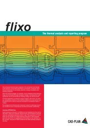
<strong>The</strong>rmal-hygro analysis<br />
<strong>ATHENA</strong> includes a light version of flixo, the leading technical software for<br />
thermal bridge analysis and reporting (isothermal computation). Now thermal<br />
bridges can be detected at the planning stage and eliminated through changes<br />
in design.<br />
<strong>The</strong> special feature with the integration of flixo in <strong>ATHENA</strong>: A detail drawing<br />
produced in <strong>ATHENA</strong> can be transferred to flixo in one<br />
working step. Here areas and materials (where known)<br />
are recognized and arcs are converted into polygons.<br />
Material changes or assignments can still be made in the<br />
flixo dialog box. After entering the internal and external<br />
temperature, a temperature computation is carried out<br />
and inserted into the <strong>ATHENA</strong> drawing.<br />
INTERFACES<br />
<strong>The</strong> previously time taken for the transfer of a detail drawing<br />
produced in <strong>CAD</strong> programs into the “Isothermal program”<br />
could easily amount to 1.5 hrs. plus the same time for<br />
modifications to the detail. <strong>The</strong> possibility of automatic<br />
transfer now reduces the time to the press of a key.<br />
Interface to LogiKal<br />
<strong>The</strong> <strong>ATHENA</strong> interface to LogiKal from Orgadata enables LogiKal profile master<br />
data to be used for the intelligent composition of profile assemblies in <strong>ATHENA</strong>.<br />
<strong>The</strong> interface offers the function of composing a cross-section of a profile assembly<br />
(e.g. mullion, press-on profile and cover section) with LogiKal master data directly<br />
in <strong>ATHENA</strong> in a dialog box and importing it into the <strong>ATHENA</strong> bar assembly manager.<br />
In <strong>ATHENA</strong> these profile assemblies can be used without restriction for the 2D and<br />
3D design, precisely as for static calculations and physical building examinations.<br />
<strong>The</strong> LogiKal range of functions for automatic profile combination takes full effect via<br />
the interface. <strong>The</strong> additional profiles suitable for a selected profile are suggested in<br />
the dialog box and positioned at the intended location. In this way LogiKal can be<br />
used as a rule-based system library in <strong>ATHENA</strong>.<br />
<strong>The</strong> bidirectional design of the interface facilitates the transfer of <strong>ATHENA</strong> constructions,<br />
e.g. of 3D models, to LogiKal for further processing, for additions or evaluations.<br />
Furthermore, the evaluations can also be implemented via the LogiKal functionality<br />
directly in <strong>ATHENA</strong>.<br />
A new feature is an <strong>ATHENA</strong> command with which projects already present in LogiKal<br />
can be imported into <strong>ATHENA</strong>. <strong>The</strong>se objects are held in <strong>ATHENA</strong> as copies and<br />
changes are also effective there. <strong>The</strong> objects can be output in <strong>ATHENA</strong> and no<br />
return to LogiKal is necessary.<br />
Interface to ERPlus<br />
<strong>ATHENA</strong> has an interface to ERPlus (ERP software from T.A. Project) with which 3D<br />
bars of 3D models, including appended assemblies, and 3D infills can be output<br />
to an XML file that can then be read in by ERPlus. Furthermore, article numbers of<br />
standard parts used in a drawing can also be passed on.
<strong>CAD</strong>-<strong>PLAN</strong> sales network worldwide:<br />
<strong>ATHENA</strong> - the solution for curtain wall<br />
design and façade engineering.<br />
• Independent of profile system<br />
• Easy to learn<br />
• With a high general validity<br />
• For engineering designs, i.e. not just drawings, but also for calculations<br />
(structural analysis, isothermals, etc.).<br />
• Excellent list of references!<br />
• Leads the market for design programs for metal construction under<br />
Auto<strong>CAD</strong>, therefore a sound investment.<br />
System requirements<br />
• Auto<strong>CAD</strong> 2008 to 2012<br />
• Auto<strong>CAD</strong> Architecture 2008 to 2013<br />
• Auto<strong>CAD</strong> Mechanical 2008 to 2013<br />
Operating system:<br />
Windows XP prof., Windows Vista or Windows 7<br />
Hardware:<br />
<strong>ATHENA</strong> requires the same hardware configuration as Auto<strong>CAD</strong>.<br />
Auto<strong>CAD</strong> – registered trade mark of Autodesk Inc.<br />
Windows XP, Vista, 7, MS-Excel – registered trade mark of Microsoft Inc.<br />
Germany: <strong>CAD</strong>-<strong>PLAN</strong> GmbH<br />
Netherlands, Belgium: <strong>CAD</strong>-<strong>PLAN</strong> GmbH<br />
Switzerland, France: ACOSOFT S.A.<br />
Portugal: Estupe<br />
Spain: MEGA Ingenieras S.L.<br />
USA, Canada, Mexico,<br />
Australia: Glaziers Center<br />
Czechia, Slovakia: TPF S.R.O.<br />
Poland: Intro Projekt<br />
Lithuania, Latvia: AGA-<strong>CAD</strong> Ltd.<br />
Russia: <strong>CAD</strong>-<strong>PLAN</strong> Russia<br />
<strong>ATHENA</strong> is independent of language.<br />
A change of language is possible<br />
even during the design. <strong>The</strong> following<br />
languages are available:<br />
• German<br />
• English<br />
• French<br />
• Italian<br />
• Dutch<br />
• Spanish<br />
• Czech<br />
• Polish<br />
• Russian<br />
• Romanian<br />
• Chinese<br />
Romania: Window & Facade Technology S.R.L.<br />
Egypt: Machines & Aluminium Centre<br />
Turkey: ORGADATA Turkey<br />
Austria: Grabmayer & Sommer GmbH<br />
Italy: TEDI<strong>CAD</strong><br />
<strong>CAD</strong>-<strong>PLAN</strong> GmbH<br />
Frankfurter Str. 59-61<br />
63067 Offenbach<br />
Germany<br />
Bulgaria: STUDIO <strong>CAD</strong><br />
Tel. +49-69-800 818-0<br />
Fax +49-69-800 818-18<br />
info@cad-plan.com<br />
www.cad-plan.com<br />
Hungary: Hungaro<strong>CAD</strong><br />
Korea: LA Curtain Wall Co. Ltd<br />
<strong>CAD</strong>-<strong>PLAN</strong> China<br />
Dubai: <strong>CAD</strong>-<strong>PLAN</strong> Middle East<br />
Malaysia: IAN Metall Engineering<br />
<strong>CAD</strong>-<strong>PLAN</strong> India