A Study Regarding the Development Trends - incdmtm
A Study Regarding the Development Trends - incdmtm
A Study Regarding the Development Trends - incdmtm

Create successful ePaper yourself
Turn your PDF publications into a flip-book with our unique Google optimized e-Paper software.
International Conference<br />
2ND International Conference on Innovations, Recent <strong>Trends</strong> and Challenges<br />
in Mechatronics, Mechanical Engineering and New High-Tech Products<br />
<strong>Development</strong><br />
MECAHITECH‘10<br />
Bucharest, 23-24 September 2010<br />
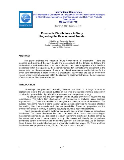
Pneumatic Distributors - A <strong>Study</strong><br />
<strong>Regarding</strong> <strong>the</strong> <strong>Development</strong> <strong>Trends</strong><br />
Mihai Avram, Constantin Bucşan<br />
Politehnica University of Bucharest,<br />
Splaiul Independentei 313 , 77206 Bucuresti,<br />
mavram02@yahoo.com<br />
ABSTRACT<br />
The paper analyzes <strong>the</strong> important future development of pneumatics. There are<br />
identified and motivated <strong>the</strong> main trends and perspectives of <strong>the</strong> domain, as follows: <strong>the</strong><br />
miniaturization and modularization of <strong>the</strong> equipment, <strong>the</strong> direct integration of <strong>the</strong> interface<br />
electronics within <strong>the</strong> equipment, <strong>the</strong> optional interface for connecting <strong>the</strong> equipment to <strong>the</strong><br />
system data bus, <strong>the</strong> development of some modulated pulses command techniques for <strong>the</strong><br />
on/off type distributors in order to obtain a proportional flow control, <strong>the</strong> use of some new<br />
type of unconventional actuators within <strong>the</strong> distributing equipment structure, <strong>the</strong> development<br />
of environmental friendly structures etc.<br />
INTRODUCTION<br />
Nowadays <strong>the</strong> pneumatic actuating systems are used in a large number of<br />
applications, due to <strong>the</strong> undoubted qualities of this type of actuators: stamina, simplicity in<br />
construction, productivity, high reliability, lower costs and non-pollutant energy.<br />
The actual stage and <strong>the</strong> development trends situates pneumatics beyond <strong>the</strong> top<br />
technologies. The future high development of pneumatics is analyzed using pertinent<br />
arguments in [1]. There are identified and analyzed <strong>the</strong> principle trends of <strong>the</strong> domain. The<br />
success rests in <strong>the</strong> results of some fascinating researches on limiting <strong>the</strong> negative effects of<br />
<strong>the</strong> working fluid low viscosity and high compressibility. These two properties are <strong>the</strong><br />
principle obstacles in <strong>the</strong> way of building accurate pneumatic positioning systems.<br />
Most pneumatic actuating systems incorporate one or more classic or proportional<br />
distributors. The classic distributors lead <strong>the</strong> compressed air to certain tracks according to<br />
<strong>the</strong> external commands. So, it is possible to invert <strong>the</strong> moving direction of <strong>the</strong> load carried by<br />
<strong>the</strong> system motor and in some cases, to stop this moving. Additionally <strong>the</strong> proportional<br />
distributors control <strong>the</strong> flowrate and <strong>the</strong>reby <strong>the</strong> speed of <strong>the</strong> actuated load. As an example,<br />
figure 1 shows <strong>the</strong> functional scheme of a pneumatic positioning system [2]. There are three<br />
distributors: two proportional ones, DP 1 and DP 2 and a classic one, DC.<br />
417
International Conference<br />
2ND International Conference on Innovations, Recent <strong>Trends</strong> and Challenges<br />
in Mechatronics, Mechanical Engineering and New High-Tech Products<br />
<strong>Development</strong><br />
MECAHITECH‘10<br />
Bucharest, 23-24 September 2010<br />
Figure 1: The functional scheme of a pneumatic positioning system<br />
PNEUMATIC DISTRIBUTING EQUIPMENT – TRENDS AND PERSPECTIVES<br />
The performances of a pneumatic actuating system depend on <strong>the</strong> performances of<br />
every equipment within its structure. In many cases <strong>the</strong> distributing equipment represents<br />
"<strong>the</strong> heart" of <strong>the</strong> pneumatic actuating system and highly influences <strong>the</strong> static and dynamic<br />
performances of <strong>the</strong> whole system. That's <strong>the</strong> reason why this paper takes regard to such<br />
equipment. An analysis of <strong>the</strong> evolution of <strong>the</strong> distributing equipment emphasizes <strong>the</strong><br />
following trends:<br />
• a sustained attention to increase <strong>the</strong> reliability, <strong>the</strong> functional accuracy and <strong>the</strong> static<br />
and dynamic performances;<br />
• decreasing <strong>the</strong> price of <strong>the</strong> equipment;<br />
• promoting <strong>the</strong> low power consumption equipment;<br />
• miniaturizing and modularizing <strong>the</strong> equipment;<br />
• <strong>the</strong> integration of <strong>the</strong> interface electronics within <strong>the</strong> equipment;<br />
• <strong>the</strong> use of optional interfaces to connect <strong>the</strong> equipment to <strong>the</strong> data bus of <strong>the</strong> system;<br />
• <strong>the</strong> development of control techniques using modulated pulses to control <strong>the</strong> on/off<br />
distributors in order to obtain <strong>the</strong> proportional flowrate control;<br />
418
International Conference<br />
2ND International Conference on Innovations, Recent <strong>Trends</strong> and Challenges<br />
in Mechatronics, Mechanical Engineering and New High-Tech Products<br />
<strong>Development</strong><br />
MECAHITECH‘10<br />
Bucharest, 23-24 September 2010<br />
• using new types of unconventional actuators within <strong>the</strong> equipment structure;<br />
• promoting environment friendly solutions.<br />
There is a large constructive variety of distributing equipment, differenced by: <strong>the</strong> type of<br />
<strong>the</strong> mobile element (sliding valve, valve), <strong>the</strong> type of <strong>the</strong> mobile element movement<br />
(translation, rotation), <strong>the</strong> number of <strong>the</strong> steady functional positions, <strong>the</strong> number of orifices,<br />
<strong>the</strong> type of <strong>the</strong> control, <strong>the</strong> presence of <strong>the</strong> preferred position. The most used types are those<br />
with cylindrical sliding valve.<br />
Well known companies in <strong>the</strong> field of pneumatics as Festo and SMC offer such<br />
distributors with acceptable static and dynamic performances. In order to improve this<br />
performances <strong>the</strong> research is focused on minimizing <strong>the</strong> weight of <strong>the</strong> mobile element,<br />
because it is <strong>the</strong> parameter that determines <strong>the</strong> response time of <strong>the</strong> equipment and its<br />
frequency response.<br />
As mentioned, <strong>the</strong>re is a large demand of distributing equipment and also a large offer.<br />
Beyond <strong>the</strong> working performances <strong>the</strong> decisive element is <strong>the</strong> price of <strong>the</strong> equipment and <strong>the</strong><br />
costs of working and maintenance.<br />
A lower price may be achieved in more ways, as follows:<br />
- using standard parts in <strong>the</strong> construction of <strong>the</strong> equipment, when possible;<br />
- using adequate manufacturing and assembly technologies, often advanced<br />
technologies, especially in <strong>the</strong> case of proportional equipment;<br />
- using new materials that are cheaper, lighter, with superior mechanical properties,<br />
more machinable and accessible.<br />
The miniaturizing of <strong>the</strong> equipment is ano<strong>the</strong>r challenge for <strong>the</strong> manufacturers. The<br />
goal is to reduce <strong>the</strong> sizes and <strong>the</strong> weight, to use less materials and energy and to reduce<br />
<strong>the</strong> cost of working and maintenance. The weight of <strong>the</strong> mobile element is also reduced and<br />
<strong>the</strong> dynamic performances increase.<br />
In <strong>the</strong> last decade <strong>the</strong> most influential trend was to build compact distributing<br />
equipment, with a high level of aggregation of <strong>the</strong> component parts in a reduced volume.<br />
Some examples are <strong>the</strong> equipment for textile industry, <strong>the</strong> automatic manufacturing and<br />
assembly lines, <strong>the</strong> robotized systems, <strong>the</strong> equipment for electronic components<br />
manufacturing. The miniaturizing of <strong>the</strong> electronic and optoelectronic components brought<br />
forward <strong>the</strong> design and manufacturing of micromechanical devices, micro-systems and<br />
miniaturized pneumatic equipment. The goals are to reduce <strong>the</strong> actuating power, to integrate<br />
in certain technologies and to develop more efficient equipment. For <strong>the</strong> integration process<br />
it is essential to build mixed pneumatic and electronic systems, where every technology<br />
participate with its specific characteristics. There were built low sizes pneumatic motors and<br />
<strong>the</strong> sizes of <strong>the</strong> distributing equipment were significantly reduced according to <strong>the</strong> reduced<br />
flowrates needed. The miniaturization requested an adequate design of <strong>the</strong> distributing<br />
section of <strong>the</strong> equipment, <strong>the</strong> optimization of <strong>the</strong> actuator and <strong>the</strong> use of new materials.<br />
The miniaturization process was initiated by building some basic pneumatic equipment<br />
(motors, distributing equipment) that were used to build pneumatic mini-systems. These<br />
equipment are similar to <strong>the</strong> conventional ones and have <strong>the</strong> same working principle. In<br />
many cases it was sufficient to reduce <strong>the</strong> scale of <strong>the</strong> equipment. One example is shown in<br />
figure 2, a. It is a Festo distributor of <strong>the</strong> MH1 type. Figure 2, b shows an "island" of such<br />
distributors, mounted on <strong>the</strong> PB base and having a common P power input orifice. The<br />
electric power signals are transmitted through <strong>the</strong> C connector, reducing <strong>the</strong> volume of <strong>the</strong><br />
equipment. The equipment has <strong>the</strong> following characteristics:<br />
- length: 10 mm;<br />
419
International Conference<br />
2ND International Conference on Innovations, Recent <strong>Trends</strong> and Challenges<br />
in Mechatronics, Mechanical Engineering and New High-Tech Products<br />
<strong>Development</strong><br />
MECAHITECH‘10<br />
Bucharest, 23-24 September 2010<br />
- nominal flowrate: 10...14 l/min;<br />
- power voltage: 5/12/24 V;<br />
- switching time: 8, 5 or 4 ms;<br />
- pressure range: -0,9...8 bar.<br />
Figure 2: a) The Festo MH1 distributor<br />
b) An "island" of distributors Figure 3: The "Airbox" module<br />
The "Airbox" module shown in figure 3 is an autonomous system including two very compact<br />
mini-distributors.<br />
The miniaturizing trend led to <strong>the</strong> development of more reduced dimensions<br />
distributing equipment, known as micro-distributors or micro-pneumatic distributors. While<br />
<strong>the</strong> classic distributors (with usual sizes) control flowrates in <strong>the</strong> range of 10.000...10 dm 3 /min<br />
(ANR - atmosphere normal reference conditions: 20 o C temperature, 65% humidity and 1013<br />
mbar pressure), <strong>the</strong> micro-distributors control flowrates lower than 1 dm 3 /min (ANR). All<br />
micro-distributors are based on a mobile element with membranes that close or open <strong>the</strong><br />
flowing area. The mobile element is controlled with specific actuators as: electromechanical,<br />
piezoelectric, electrostatic, <strong>the</strong>rmal, shape memory, electrolytic, etc.<br />
The difference between mini and micro - pneumatics is not neat set out. The two<br />
concepts use first to measure <strong>the</strong> possibilities of miniaturizing in pneumatics.<br />
The manufacturers already use silicon - <strong>the</strong> material used for microprocessors and AI - in<br />
order to miniaturize pneumatic equipments. There were built silicon chips with etched<br />
structure capable to direct <strong>the</strong> air flow. This distributors have virtually null intake power, <strong>the</strong>ir<br />
response time is much lower than 1 ms, and <strong>the</strong>y are made of silicon. This means that it is<br />
possible to build <strong>the</strong> electronic circuits on <strong>the</strong> same substrate. This concept work, as showed<br />
by <strong>the</strong> developed prototypes. The input voltage must be 150 V, but <strong>the</strong> intake power is<br />
virtually null, <strong>the</strong> mobile element being moved by <strong>the</strong> force of <strong>the</strong> electrostatic field.<br />
Figure 4 shows a micro-distributor with electrostatic actuation [3].<br />
The upper side of <strong>the</strong> distributor is a SiO 2 membrane covered with a thin layer of<br />
chrome acting as a mobile electrode. The body of <strong>the</strong> distributor is made of silicon and a<br />
passing orifice is etched on it. The membrane stays in <strong>the</strong> proffered upper position due to<br />
internal stresses. When a control voltage is applied to <strong>the</strong> poly-silicon electrodes <strong>the</strong><br />
membrane is pushed down and <strong>the</strong> flow is stopped.<br />
420
International Conference<br />
2ND International Conference on Innovations, Recent <strong>Trends</strong> and Challenges<br />
in Mechatronics, Mechanical Engineering and New High-Tech Products<br />
<strong>Development</strong><br />
MECAHITECH‘10<br />
Bucharest, 23-24 September 2010<br />
Figure 4: The scheme of a micro-distributor with electrostatic actuation<br />
The experimental models have flow areas in <strong>the</strong> range of 10x10 µm to 100x100 µm,<br />
<strong>the</strong> membrane dimensions are in <strong>the</strong> range of 80...1000 µm and <strong>the</strong> thickness is in <strong>the</strong> range<br />
of 20...120 µm. The blocking voltage is 68 V and <strong>the</strong> working voltage is 120 V. The<br />
equipment is nonsensitive to electromagnetic fields and supports mechanical shocks due to<br />
<strong>the</strong> very low weight of <strong>the</strong> mobile element. Ano<strong>the</strong>r advantage consist in <strong>the</strong> possibility to<br />
build more distributors on one substrate.<br />
Figure 5 shows <strong>the</strong> construction of a <strong>the</strong>rmal controlled micro-distributor developed by<br />
IFAS and FhG - ISIT from Itzehoe, Germany [4].<br />
Figure 5: The IFAS and FhG - ISIT<br />
<strong>the</strong>rmal controlled micro-distributor<br />
Figure 6: The dynamic characteristic<br />
A pre-tensioned nickel bridge is warmed and suspended, allowing <strong>the</strong> control of a<br />
nozzle. Due to <strong>the</strong> used physical principle <strong>the</strong> needed input power is less than 1 W to<br />
modulate pressures up to 10 bar. The distributor may be of <strong>the</strong> two or three ways type and it<br />
has a proportional working mode. The main advantage of this distributor is <strong>the</strong> relative long<br />
stroke: 40 µm. Even if <strong>the</strong> distributor is <strong>the</strong>rmal controlled it has excellent dynamic<br />
performances as shown in figure 6. The response time for a 90% step input signal is about<br />
16 ms. The maximum flowrate of <strong>the</strong> <strong>the</strong>rmal controlled distributor is ten times larger than <strong>the</strong><br />
maximum flowrate of <strong>the</strong> electrostatic distributor, due to <strong>the</strong> longer stroke. The <strong>the</strong>rmal<br />
controlled distributor may be used as a pilot, with no need for an amplifier.<br />
The control interfaces for such equipment are designed as cards or modules. A<br />
modern development trend is to integrate <strong>the</strong> electronic interface directly within <strong>the</strong><br />
equipment, that becomes a mechatronic structure controlling <strong>the</strong> pneumatic parameter<br />
421
International Conference<br />
2ND International Conference on Innovations, Recent <strong>Trends</strong> and Challenges<br />
in Mechatronics, Mechanical Engineering and New High-Tech Products<br />
<strong>Development</strong><br />
MECAHITECH‘10<br />
Bucharest, 23-24 September 2010<br />
through an electric control signal. There are yet unsolved problems in connection with <strong>the</strong><br />
environment and especially with <strong>the</strong> temperature, that decisively influences <strong>the</strong> working of<br />
<strong>the</strong> electronic components within optimum parameters. Figure 7 shows a proportional<br />
distributor manufactured by Norgren, having direct actuation and position control for <strong>the</strong><br />
mobile element using a microprocessor integrated within <strong>the</strong> equipment.<br />
Figure 7: The Norgren proportional distributor<br />
The characteristics of <strong>the</strong> equipment are <strong>the</strong> following:<br />
- <strong>the</strong> digital micro-controller assures a high stability and a superior dynamics for <strong>the</strong><br />
mobile element of <strong>the</strong> equipment;<br />
- linear characteristic and minimum hysteresis;<br />
- very good sensitivity;<br />
- high flowrate range;<br />
- very good sealing;<br />
- zero cover;<br />
- low pressure loss;<br />
- PC configurable using <strong>the</strong> V24 interface;<br />
- <strong>the</strong> control signal: 4...20 mA; ±5 V; 0...10 V.<br />
The pneumatic equipment manufacturers offer an optional interface to connect directly to<br />
<strong>the</strong> data bus. Figure 8 shows such an equipment using integrated digital electronics and<br />
environment monitoring functions. The bus module transmits <strong>the</strong> digital commands for<br />
automations. O<strong>the</strong>r distributor modules and I/O modules are connected to a circuit that is<br />
independent of <strong>the</strong> bus protocol. This allows <strong>the</strong> diagnose to <strong>the</strong> distributor or coil level.<br />
Power, transmitting or configuring errors may be detected at <strong>the</strong> system level. Power, output<br />
and input errors may be detected at <strong>the</strong> distributor or coil level. In <strong>the</strong> case of distributors with<br />
feedback functions a variation of <strong>the</strong> signal larger than <strong>the</strong> permitted one will produce an<br />
error message. The error is easily eliminated by replacing <strong>the</strong> components or by stopping <strong>the</strong><br />
process.<br />
Beside <strong>the</strong> analogical proportional pneumatic distributors, <strong>the</strong>re were developed<br />
proportional distributors with discrete working. Using adequate control techniques based on<br />
<strong>the</strong> modulation of <strong>the</strong> electromagnet power pulses, this distributors assures <strong>the</strong> control of <strong>the</strong><br />
average flowrate, while <strong>the</strong> control of <strong>the</strong> instantaneous flowrate is not possible. These are,<br />
in fact, electric actuated 3/2 micro-distributors with preferential position, with a mobile<br />
element that is not a slider but often a valve. The actuation is performed by a classic<br />
electromagnet and <strong>the</strong> working is of <strong>the</strong> type "all or nothing". In this case <strong>the</strong> mobile element<br />
422
International Conference<br />
2ND International Conference on Innovations, Recent <strong>Trends</strong> and Challenges<br />
in Mechatronics, Mechanical Engineering and New High-Tech Products<br />
<strong>Development</strong><br />
MECAHITECH‘10<br />
Bucharest, 23-24 September 2010<br />
opens and shuts <strong>the</strong> inner circuit with a high frequency (≈ 200 Hz), allowing <strong>the</strong> control of <strong>the</strong><br />
average flowrate. The main advantages of this distributors are <strong>the</strong> following: high response<br />
speed, acceptable price (<strong>the</strong> construction is simple and does not need special manufacturing<br />
and assembly conditions), <strong>the</strong> elimination of hysteresis and its unwanted effects, a very good<br />
repeatability. An actuating system that integrates such equipment may be controlled by a<br />
digital microprocessor, which simplifies <strong>the</strong> control system structure.<br />
Figure 8: Pneumatic equipment with integrated digital electronics<br />
Some control techniques [5] are based on mixing up <strong>the</strong> outputs of more microdistributors<br />
of <strong>the</strong> same type, grouped in "batteries", and especially on controlling <strong>the</strong><br />
opening and shutting time of <strong>the</strong> distributor flowing area. The used control methods may be<br />
classified as follows:<br />
a. flowrate control methods based on coupling more distributors: <strong>the</strong> PNM method<br />
(“Pulse Number Modulation”) and <strong>the</strong> PCM method (“Pulse Cod Modulation”);<br />
b. flowrate control methods using modulated control signals: <strong>the</strong> PFM method<br />
(“Pulse Frequency Modulation”) and <strong>the</strong> PWM method (“Pulse Width Modulation”);<br />
c. mixed flowrate control methods.<br />
Beside <strong>the</strong> consecrated actuators (<strong>the</strong> classic electromagnet and <strong>the</strong> proportional<br />
one) <strong>the</strong>re were developed ano<strong>the</strong>r types of unconventional actuators, as: piezoelectric<br />
actuators, magneto-strictive actuators, actuators without mobile elements (with electroviscous<br />
or magnetic fluids).<br />
Piezoelectric actuators are <strong>the</strong> most interesting. Figure 9 shows two, a linear one (figure 9,a)<br />
and a bimorph actuator (figure 9,b).<br />
Figure 9: Micro-distributors with piezoelectric actuators<br />
In <strong>the</strong> first case (figure 9,a), when <strong>the</strong> actuator is not commanded, <strong>the</strong> position of <strong>the</strong><br />
beam 3 determines <strong>the</strong> valve S 1 to close <strong>the</strong> orifice (1), and so <strong>the</strong> orifice (2) is connected to<br />
423
International Conference<br />
2ND International Conference on Innovations, Recent <strong>Trends</strong> and Challenges<br />
in Mechatronics, Mechanical Engineering and New High-Tech Products<br />
<strong>Development</strong><br />
MECAHITECH‘10<br />
Bucharest, 23-24 September 2010<br />
<strong>the</strong> orifice (3). When <strong>the</strong> control voltage is applied to <strong>the</strong> actuator 2, <strong>the</strong> length of <strong>the</strong> actuator<br />
increases (<strong>the</strong> elongation is about 5 … 10 µm, according to <strong>the</strong> applied voltage), <strong>the</strong><br />
generated force determines <strong>the</strong> buckling of <strong>the</strong> beam and <strong>the</strong> valve S 2 closes <strong>the</strong> orifice (3),<br />
while <strong>the</strong> valve S 1 opens <strong>the</strong> orifice (1) which is now connected to <strong>the</strong> orifice (2). In this case<br />
<strong>the</strong> beam 3 works as a mechanical amplifier of <strong>the</strong> actuator displacement.<br />
In <strong>the</strong> second case (figure 9,b), <strong>the</strong> beam 2 consist of at least two piezoelectric<br />
segments, bonded with each o<strong>the</strong>r, or both bonded on a metallic segment. When <strong>the</strong> control<br />
voltage is applied to <strong>the</strong> piezoelectric segments, <strong>the</strong> free end of <strong>the</strong> beam moves<br />
proportionally with <strong>the</strong> voltage value.<br />
The proportionality factor depend on <strong>the</strong> sizes of <strong>the</strong> segments and on <strong>the</strong> used<br />
materials. This actuators have <strong>the</strong> advantage that produce a displacement of tenths of a<br />
millimeter, but <strong>the</strong> developed forces are very small (of about 0,5 N).<br />
The problem of <strong>the</strong> environment pollution was first connected to <strong>the</strong> industrial areas.<br />
The next step was to analyze <strong>the</strong> technologies and so <strong>the</strong> notion "clean technology" was<br />
born. The actual approach is to analyze <strong>the</strong> product along its hole life cycle, starting with <strong>the</strong><br />
manufacture of <strong>the</strong> materials, design, manufacture, transport and operation, and finishing<br />
with <strong>the</strong> possibilities of recycling or return to nature in a non-polluting form. This are also<br />
valid for pneumatic equipment.<br />
CONCLUSIONS<br />
The development of <strong>the</strong> pneumatic distributors domain was imposed by demands of<br />
automation technologies. Pneumatics was one of <strong>the</strong> main innovation factors in fluid power<br />
domain. The trends of miniaturization, increase of dynamic performances, piezoelectric<br />
technologies, and <strong>the</strong> use of <strong>the</strong> connection to <strong>the</strong> data bus, appeared in pneumatics earlier<br />
<strong>the</strong>n in hydraulics. A recent trend in distributors development is <strong>the</strong> use of reduced sizes<br />
micro-distributors, with low energy consumption, made of silicon using etching technologies.<br />
The on/off distributors can reach similar performances as <strong>the</strong> analogical equipment using<br />
modulated pulses control, and this is why <strong>the</strong>y are interesting for <strong>the</strong> designers.<br />
REFERENCES<br />
[1] Vogel, G., Mühlberger, E., L’univers fascinant de la pneumatique, HOPE Internationa<br />
Communication, 2003 :<br />
[2] Avram M., Bucsan C., Pneutronic Positioning Unit - Part 1: Design and Working Principle,<br />
Romanian Review of Precision Mechanics, Optics and Mecatronics 2009 (19), No.36;<br />
pag.7…10;<br />
[3] Haji Babaei, J., A New Bistabile Microvalve Using SIO 2 Beam as Movable Part, Proc. Of<br />
Int. Conf. On New Actuators, Bremen, 1994, pag.34...37;<br />
[4] Gün<strong>the</strong>r, Götz; Quenzer, Hans-Joachim: Entwicklung eines pneumatischen Mikroventils.<br />
O+P “Ölhydraulik und Pneumatik” 44 (2000) Nr. 9;<br />
[5] Avram, M., AcŃionări hidraulice şi pneumatice – Echipamente şi sisteme clasice şi<br />
mecatronice, Editura Universitară, Bucureşti, 2005.<br />
424