Webasto Air Top HL32 D Workshop Manual
A workshop manual for all versions of the series HL24/32 Petrol and Diesel as as Air Top 24/32 Petrol and Diesel heaters.
A workshop manual for all versions of the series HL24/32 Petrol and Diesel as as Air Top 24/32 Petrol and Diesel heaters.
- TAGS
- webasto
You also want an ePaper? Increase the reach of your titles
YUMPU automatically turns print PDFs into web optimized ePapers that Google loves.
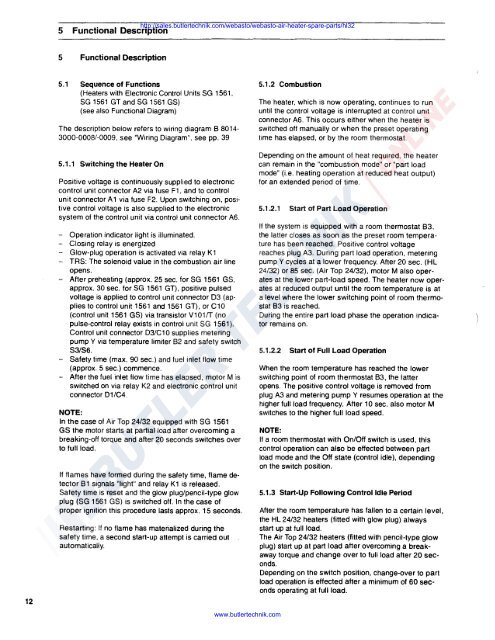
5 Functional Description<br />
http://sales.butlertechnik.com/webasto/webasto-air-heater-spare-parts/hl32<br />
5 Functional Description<br />
5.1 Sequence of Functions<br />
(Heaters with Electronic Control Units SG 1561,<br />
SG 1561 GT and SG 1561 GS)<br />
(see also Functional Diagram)<br />
The description below refers to wiring diagram 8 8014-<br />
3000-0008/-0009, see "Wiring Diagram", see pp. 39<br />
5.1.2 Combustion<br />
The heater, which is now operating. continues to run<br />
until the control voltage is interrupted at control unit<br />
connector A6. This occurs either when the heater is<br />
switched off manually or when the preset operating<br />
time has elapsed, or by the room thermostat.<br />
12<br />
5.1.1 Switching the Heater On<br />
Positive voltage is continuously supplied to electronic<br />
control unit connector A2 via fuse F1, and to control<br />
unit connector A 1 via fuse F2. Upon switching on, positive<br />
control voltage is also supplied to the electronic<br />
system of the control unit via control unit connector A6.<br />
- Operation indicator light is illuminated.<br />
- Closing relay is energized<br />
- Glow-plug operation is activated via relay K1<br />
- TRS: The solenoid value in the combustion air line<br />
opens.<br />
- After preheating (approx. 25 sec. for SG 1561 GS,<br />
approx. 30 sec. for SG 1561 GT), positive pulsed<br />
voltage is applied to control unit connector 03 (applies<br />
to control unit 1561and1561 GT), or C10<br />
(control unit 1561 GS) via transistor v101rr (no<br />
pulse-control relay exists in control unit SG 1561 ).<br />
Control unit connector D3/C10 supplies metering<br />
pump Y via temperature limiter 82 and safety switch<br />
83/86.<br />
- Safety time (max. 90 sec.) and fuel inlet flow time<br />
(approx. 5 sec.) commence.<br />
- After the fuel inlet flow time has elapsed, motor Mis<br />
switched on via relay K2 and electronic control unit<br />
connector D1/C4.<br />
NOTE:<br />
In the case of <strong>Air</strong> <strong>Top</strong> 24/32 equipped with SG 1561<br />
GS the motor starts at partial load after overcoming a<br />
breaking-off torque and after 20 seconds switches over<br />
to full load.<br />
If flames have formed during the safety time, flame detector<br />
81 signals "light" and relay K1 is released.<br />
Safety time is reset and the glow plug/pencil-type glow<br />
plug (SG 1561 GS) is switched off. In the case of<br />
proper ignition this procedure lasts approx. 15 seconds.<br />
Restarting: If no flame has materialized during the<br />
safety time, a second start-up attempt is carried out<br />
automatically.<br />
www.butlertechnik.com<br />
Depending on the amount of heat required, the heater<br />
can remain in the "combustion mode" or "part load<br />
mode" (i.e. heating operation at reduced heat output)<br />
for an extended period of time.<br />
5.1.2.1 Start of Part Load Operation<br />
If the system is equipped with a room thermostat 83.<br />
the latter closes as soon as the preset room temperature<br />
has been reached. Positive control voltage<br />
reaches plug A3. During part load operation, metering<br />
pump Y cycles at a lower frequency. After 20 sec. (HL<br />
24/32) or 85 sec. (<strong>Air</strong> <strong>Top</strong> 24/32), motor M also operates<br />
at the lower part-load speed. The heater now operates<br />
at reduced output until the room temperature is at<br />
a level where the lower switching point of room thermostat<br />
83 is reached.<br />
During the entire part load phase the operation indicator<br />
remains on.<br />
5.1.2.2 Start of Full Load Operation<br />
When the room temperature has reached the lower<br />
switching point of room thermostat 83, the latter<br />
opens. The positive control voltage is removed from<br />
plug A3 and metering pump Y resumes operation at the<br />
higher full load frequency. After 10 sec. also motor M<br />
switches to the higher full load speed.<br />
NOTE:<br />
If a room thermostat with On/Off switch is used, this<br />
control operation can also be effected between part<br />
load mode and the Off state (control idle), depending<br />
on the switch position.<br />
5.1.3 Start-Up Following Control Idle Period<br />
After the room temperature has fallen to a certain level,<br />
the HL 24/32 heaters (fitted with glow plug) always<br />
start up at full load.<br />
The <strong>Air</strong> <strong>Top</strong> 24/32 heaters (fitted with pencil-type glow<br />
plug) start up at part load after overcoming a breakaway<br />
torque and change over to full load after 20 seconds.<br />
Depending on the switch position, change-over to part<br />
load operation is effected after a minimum of 60 seconds<br />
operating at full load.


