Webasto Air Top HL32 D Workshop Manual
A workshop manual for all versions of the series HL24/32 Petrol and Diesel as as Air Top 24/32 Petrol and Diesel heaters.
A workshop manual for all versions of the series HL24/32 Petrol and Diesel as as Air Top 24/32 Petrol and Diesel heaters.
- TAGS
- webasto

Create successful ePaper yourself
Turn your PDF publications into a flip-book with our unique Google optimized e-Paper software.
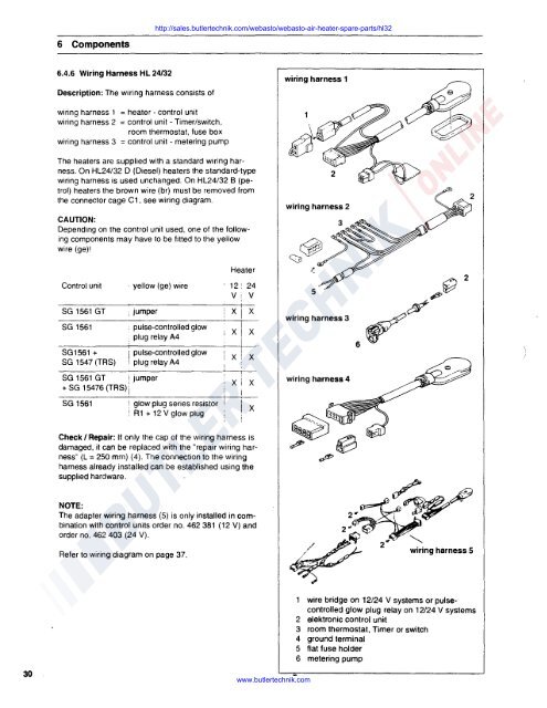
6 Components<br />
http://sales.butlertechnik.com/webasto/webasto-air-heater-spare-parts/hl32<br />
6.4.6 Wiring Harness HL 24/32<br />
Description: The wiring harness consists of<br />
wiring harness 1<br />
wiring harness 1 = heater - control unit<br />
wiring harness 2 = control unit - Timer/switch,<br />
room thermostat, fuse box<br />
wiring harness 3 = control unit - metering pump<br />
The heaters are supplied with a standard wiring harness.<br />
On HL24/32 D (Diesel) heaters the standard-type<br />
wiring harness is used unchanged. On HL24/32 B (petrol)<br />
heaters the brown wire (br) must be removed from<br />
the connector cage C1. see wiring diagram.<br />
CAUTION:<br />
Depending on the control unit used, one of the following<br />
components may have to be fitted to the yellow<br />
wire (ge)I<br />
wiring harness 2<br />
Heater<br />
Control unit · yellow (ge) wire 12! 24<br />
V: v<br />
SG 1561 GT , jumper xj x<br />
SG 1561 • pulse-controlled glow i<br />
. plug relay A4<br />
XI x<br />
SG1561 + I pulse-controlled glow<br />
SG 1547 (TRS) ', plug relay A4<br />
SG 1561 GT i jumper<br />
+ SG 15476 {TRS) j<br />
SG 1561 ! glow plug series resistor<br />
x<br />
! A1 + 12 V glow plug<br />
x<br />
x<br />
x<br />
x<br />
5 ~~<br />
wlrlnghamess3 ~~<br />
wiring harness 4<br />
6<br />
2<br />
Check I Repair: If only the cap of the wiring harness is<br />
damaged, it can be replaced with the "repair wiring harness"<br />
(L = 250 mm) (4). The connection to the wiring<br />
harness already installed can be established using the<br />
supplied hardware.<br />
NOTE:<br />
The adapter wiring harness (5) is only installed in combination<br />
with control units order no. 462 381 { 12 V) and<br />
order no. 462 403 (24 V).<br />
Refer to wiring diagram on page 37.<br />
~~ A9<br />
2~~~<br />
2~~<br />
/~.,..,,, 2~ '--..<br />
~ "/- wiring harness 5<br />
30<br />
www.butlertechnik.com<br />
wire bridge on 12/24 V systems or pulsecontrolled<br />
glow plug relay on 12/24 V systems<br />
2 elektronic control unit<br />
3 room thermostat, Timer or switch<br />
4 ground terminal<br />
5 flat fuse holder<br />
6 metering pump