How to EncodE and dEcodE InformatIon
How to EncodE and dEcodE InformatIon
How to EncodE and dEcodE InformatIon

You also want an ePaper? Increase the reach of your titles
YUMPU automatically turns print PDFs into web optimized ePapers that Google loves.
IT Zone<br />
<strong>How</strong> <strong>to</strong> Encode <strong>and</strong><br />
Decode Information<br />
Learn <strong>to</strong> convert between various codes for digital data transmission<br />
• C.T. Bhunia<br />
Digital data is represented,<br />
s<strong>to</strong>red <strong>and</strong> exchanged in<br />
the form of codes written in<br />
strings of 0’s <strong>and</strong> 1’s known as bits.<br />
And encoding <strong>and</strong> decoding is an<br />
art of transforming one representation<br />
in<strong>to</strong> another <strong>and</strong> vice versa. In<br />
accounts section of offices, employee<br />
codes are used for salary disbursement.<br />
The code is a unique number<br />
given <strong>to</strong> the employee name. Decoding<br />
is getting the employee details<br />
from the code.<br />
In computer engineering, encoding<br />
<strong>and</strong> decoding are used for transformation<br />
of numerical data from one<br />
system <strong>to</strong> another system for specific<br />
use. There are different kinds of binary<br />
codes, like weighted <strong>and</strong> non-weighted<br />
codes, reflected codes, sequential<br />
codes, alphanumeric codes, <strong>and</strong> error<br />
detection <strong>and</strong> correction codes.<br />
Weighted code<br />
Converting decimal data in<strong>to</strong> binary<br />
<strong>and</strong> vice versa is essential for computing<br />
as the computer realises only<br />
binary data from ‘on’ <strong>and</strong> ‘off’ states<br />
of the transis<strong>to</strong>r built in<strong>to</strong> the system.<br />
Binary codes are the codes that are<br />
represented in binary system with<br />
modification from the original ones.<br />
There are two such codes: weighted<br />
binary codes <strong>and</strong> non-weighted<br />
codes.<br />
In addition <strong>to</strong> conversion of the<br />
number system, it is often desirable <strong>to</strong><br />
retain decimal character even when it<br />
is encoded in binary digits, or bits (1<br />
or 0). For example, consider decimal<br />
number 56, where we represent individual<br />
decimal digits, namely, 5 <strong>and</strong> 6,<br />
as 0101 for 5 <strong>and</strong> 0110 as 6:<br />
56=01010110<br />
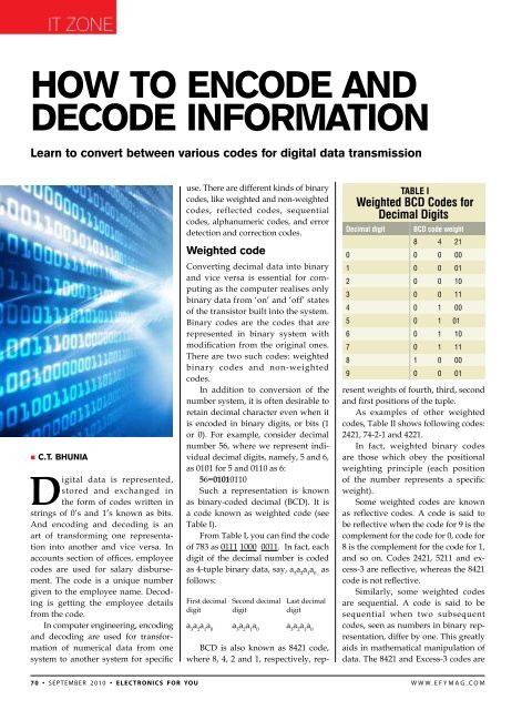
Such a representation is known<br />
as binary-coded decimal (BCD). It is<br />
a code known as weighted code (see<br />
Table I).<br />
From Table I, you can find the code<br />
of 783 as 0111 1000 0011. In fact, each<br />
digit of the decimal number is coded<br />
as 4-tuple binary data, say, a 3<br />
a 2<br />
a 1<br />
a 0 ,<br />
as<br />
follows:<br />
First decimal Second decimal Last decimal<br />
digit digit digit<br />
a 3<br />
a 2<br />
a 1<br />
a 0<br />
a 3<br />
a 2<br />
a 1<br />
a 0<br />
a 3<br />
a 2<br />
a 1<br />
a 0<br />
BCD is also known as 8421 code,<br />
where 8, 4, 2 <strong>and</strong> 1, respectively, rep-<br />
Table I<br />
Weighted BCD Codes for<br />
Decimal Digits<br />
Decimal digit<br />
BCD code weight<br />
8 4 21<br />
0 0 0 00<br />
1 0 0 01<br />
2 0 0 10<br />
3 0 0 11<br />
4 0 1 00<br />
5 0 1 01<br />
6 0 1 10<br />
7 0 1 11<br />
8 1 0 00<br />
9 0 0 01<br />
resent weights of fourth, third, second<br />
<strong>and</strong> first positions of the tuple.<br />
As examples of other weighted<br />
codes, Table II shows following codes:<br />
2421, 74-2-1 <strong>and</strong> 4221.<br />
In fact, weighted binary codes<br />
are those which obey the positional<br />
weighting principle (each position<br />
of the number represents a specific<br />
weight).<br />
Some weighted codes are known<br />
as reflective codes. A code is said <strong>to</strong><br />
be reflective when the code for 9 is the<br />
complement for the code for 0, code for<br />
8 is the complement for the code for 1,<br />
<strong>and</strong> so on. Codes 2421, 5211 <strong>and</strong> excess-3<br />
are reflective, whereas the 8421<br />
code is not reflective.<br />
Similarly, some weighted codes<br />
are sequential. A code is said <strong>to</strong> be<br />
sequential when two subsequent<br />
codes, seen as numbers in binary representation,<br />
differ by one. This greatly<br />
aids in mathematical manipulation of<br />
data. The 8421 <strong>and</strong> Excess-3 codes are<br />
70 • september 2010 • electronics for you www.efymag.com
IT Zone<br />
sequential, whereas the 2421 <strong>and</strong> 5211<br />
codes are not sequential.<br />
Some features of<br />
weighted codes<br />
Except 8421 <strong>and</strong> 74-2-1 codes, for all<br />
other weighted codes some of the decimal<br />
number may be coded in more than<br />
one forms. For example, decimal 4 in<br />
2421 code may be represented as 1010<br />
or 0100. That’s why 2421 <strong>and</strong> 4221 are<br />
known as self-complementing codes.<br />
A property known as self-complementing<br />
is applied <strong>to</strong> select a code<br />
out of different options. The property<br />
is stated as follows: If ‘D’ is the given<br />
decimal number, you may code it in<br />
any option, but then decimal number<br />
9-D must be coded taking the option<br />
such that the code is bit-wise complement<br />
of the code of D. For example, if<br />
decimal 4 in 2421 is coded as 0100, then<br />
9-4=5 must be coded as 1011. See that<br />
1011 is bit-wise complement of 0100.<br />
We have shown the code in Table<br />
II applying the self-complementing<br />
property. A necessary condition of<br />
self-complementing property is that<br />
the sum of weights in the code is 9.<br />
The codes 8421 <strong>and</strong> 74-2-1 are not selfcomplementing.<br />
Non-weighted code<br />
In many cases, there may be some<br />
requirement for non-weighted codes<br />
(see Table III), particularly from design<br />
point of view. Non-weighted codes are<br />
codes that are not positionally weighted.<br />
That is, each position within the<br />
binary number is not assigned a fixed<br />
value. The examples of a few nonweighted<br />
codes are excess-3 code, 1-<strong>to</strong>-<br />
2 code <strong>and</strong> BCDP (BCD with parity).<br />
Excess-3 is a non-weighted code<br />
used <strong>to</strong> express decimal numbers. The<br />
code derives its name from the fact that<br />
each binary code is the corresponding<br />
8421 code plus 0011(3).<br />
Some features of nonweighted<br />
code<br />
Excess-3 code is just BCD with plus 3<br />
weight. If ‘d’ is the decimal number,<br />
d+3 is coded in 8421 <strong>to</strong> get the excess-3<br />
code. This code is the most important<br />
non-weighted code in digital logic design.<br />
1-<strong>to</strong>-2 code has a unique feature.<br />
No code has less than one <strong>and</strong> greater<br />
than two 1’s. BCDP (with odd parity) is<br />
designed so as <strong>to</strong> make any code having<br />
odd numbers of 1’s. This is done<br />
with selection of parity bit, which is the<br />
right-most bit of the code.<br />
Gray code/binary<br />
reflected code<br />
Table II<br />
Weighted Codes<br />
Decimal digit<br />
2421 code 74-2-1 code 4221 code<br />
Weight 2 4 2 1 Weight 7 4 -2 -1 Weight 4 2 2 1<br />
0 0 0 0 0 0 0 0 0 0 0 0 0<br />
1 0 0 0 1 0 1 1 1 0 0 0 1<br />
2 0 0 1 0 0 1 1 0 0 0 1 0<br />
3 0 0 1 1 0 1 0 1 0 0 1 1<br />
4 0 1 0 0 0 1 0 0 0 1 1 0<br />
5 1 0 1 1 1 0 1 0 1 0 0 1<br />
6 1 1 0 0 1 0 0 1 1 1 0 0<br />
7 1 1 0 1 1 0 0 0 1 1 0 1<br />
8 1 1 1 0 1 1 1 1 1 1 1 0<br />
9 1 1 1 1 1 1 1 0 1 1 1 1<br />
Decimal digit<br />
Table III<br />
Non-weighted Codes<br />
Excess-3 code<br />
(XS-3 code)<br />
1-<strong>to</strong>-2 code<br />
Gray code is a very important nonweighted<br />
code. An N-bit gray code is<br />
a sequence of all the N-bit binary numbers,<br />
ordered in such a way that each<br />
binary number differs from its predecessor<br />
<strong>and</strong> successor by exactly 1 bit<br />
(<strong>and</strong> the first <strong>and</strong> last differ by one bit<br />
also). For example, one-bit gray code<br />
0, 1 <strong>and</strong> three-bit gray<br />
code 000, 001, 011, 010,<br />
110, 111, 101, 100 (differs<br />
from 000 by 1 bit).<br />
The sequence 00, 11, 01,<br />
10 is not a two-bit gray<br />
code as the first <strong>and</strong><br />
second elements differ<br />
by two bits.<br />
Table IV shows a<br />
4-bit code in comparison<br />
with a binary number.<br />
In the column of<br />
decimal number, it is<br />
seen that from 00 <strong>to</strong> 09<br />
if you move from number<br />
N <strong>to</strong> number N+1,<br />
there is a change in<br />
only one digit. But when you<br />
move from 09 <strong>to</strong> 10, there are<br />
changes in two digit positions.<br />
Look at the column of reflected<br />
decimal number: as you move<br />
from N <strong>to</strong> N+1, always there<br />
is change in one digit position.<br />
In binary representation as<br />
we move from N <strong>to</strong> N+1, there<br />
may be many changes in bits.<br />
For example, as you go from 3<br />
<strong>to</strong> 4, there are as many as three<br />
changes in bit position. But,<br />
look at the reflected binary or<br />
gray code: as you move from<br />
any N <strong>to</strong> N+1, always there<br />
is only one change in bit position.<br />
This is the property of gray code<br />
or reflected binary code. Gray code<br />
is also known as a variable weighted<br />
code <strong>and</strong> is cyclic.<br />
The gray code is called ‘reflected<br />
binary,’ because the first eight values<br />
compare with those of the last eight<br />
values, but in reverse order. The gray<br />
code belongs <strong>to</strong> a class of codes called<br />
‘minimum change codes,’ in which<br />
only one bit in the code changes when<br />
moving from one code <strong>to</strong> the next. The<br />
gray code is a reflective digital code<br />
which has a special property that any<br />
two subsequent numbers’ codes differ<br />
by only one bit. It is also called ‘unitdistance<br />
code.’<br />
Gray code has an important application<br />
in digital control systems. Let<br />
BCDP (with<br />
odd parity)<br />
0 0 0 1 1 0 0 0 1 0 0 0 0 1<br />
1 0 1 0 0 0 0 1 0 0 0 0 1 0<br />
2 0 1 0 1 0 0 1 1 0 0 1 0 0<br />
3 0 1 1 0 0 1 0 0 0 0 1 1 1<br />
4 0 1 1 1 0 1 0 1 0 1 0 0 0<br />
5 1 0 0 0 0 1 1 0 0 1 0 1 1<br />
6 1 0 0 1 1 0 0 0 0 1 1 0 1<br />
7 1 0 1 0 1 0 0 1 0 1 1 1 0<br />
8 1 0 1 1 1 0 1 0 1 0 0 0 0<br />
9 1 1 0 1 1 1 0 0 1 0 0 1 1<br />
72 • september 2010 • electronics for you www.efymag.com
IT Zone<br />
Decimal<br />
Table IV<br />
Gray/Reflected Code<br />
Reflected<br />
decimal<br />
Binary<br />
b 3<br />
b 2<br />
b 1<br />
b 0<br />
us take the example of a fan regula<strong>to</strong>r<br />
which is digitally controlled. You want<br />
<strong>to</strong> switch from position 3 <strong>to</strong> 4. If you<br />
follow the normal binary system, you<br />
need <strong>to</strong> change three bit positions <strong>to</strong><br />
switch from 3 <strong>to</strong> 4. But how? Change<br />
three positions one after another as<br />
shown in Table V.<br />
In gray code, there is change in<br />
only one position, so there will be no<br />
oscillation as such. The code is called<br />
reflected because it can be generated<br />
in the following manner: Take the<br />
gray code 0, 1. Write it forwards, then<br />
backwards: 0, 1, 1, 0. Then prepend 0’s<br />
Reflected binary/gray code<br />
g 3<br />
g 2<br />
g 1<br />
g 0<br />
00 00 0000 0000<br />
01 01 0001 0001<br />
02 02 0010 0011<br />
03 03 0011 0010<br />
04 04 0100 0110<br />
05 05 0101 0111<br />
06 06 0110 0101<br />
07 07 0111 0100<br />
08 08 1000 1100<br />
09 09 1001 1101<br />
10 19 1010 1111<br />
11 18 1011 1110<br />
12 17 1100 1010<br />
13 16 1101 1011<br />
14 15 1110 1001<br />
15 14 1111 1000<br />
16 13<br />
17 12<br />
18 11<br />
19 10<br />
Table V<br />
Illustration of Property of Gray Code<br />
<strong>to</strong> the first half <strong>and</strong> 1’s <strong>to</strong><br />
the second half: 00, 01, 11,<br />
10. Continuing, write 00,<br />
01, 11, 10, 10, 11, 01, 00 <strong>to</strong><br />
obtain 000, 001, 011, 010,<br />
110, 111, 101, 100. Each iteration<br />
therefore doubles<br />
the number of codes.<br />
Algorithm for<br />
binary-<strong>to</strong>-gray<br />
conversion<br />
This is very simple:<br />
1. The most significant<br />
bit of the binary number<br />
is the most significant bit<br />
of the gray code<br />
2. Add (using modulo<br />
2, i.e., ignoring carry)<br />
the next significant bit of<br />
the binary number <strong>to</strong> the<br />
next significant bit of the<br />
binary number <strong>to</strong> obtain<br />
the next gray code bit.<br />
3. Repeat step 2 until<br />
all bits of the binary bits<br />
have been added modulo<br />
2. The resultant number is<br />
Present number Action Next number<br />
0011 (=3) Starting position Change in the first position from right 0010 (=2)<br />
0010(=2) Change in the second position from right 0000(=0)<br />
0000(=0) Change in the third position from right 0100(=4) Final position<br />
Comment: So for a change from regulating position 3 <strong>to</strong> 4, the fan will go a round of 3 <strong>to</strong> 2 <strong>to</strong> 0 <strong>to</strong> 4.<br />
This will cause huge oscillation in the circuit, which is not a good design.<br />
the gray code equivalent of the binary<br />
number.<br />
Assume binary number b 3<br />
b 2<br />
b 1<br />
b 0<br />
= 0011. Conversion in<strong>to</strong> gray is done<br />
as follows: g 3<br />
= b 3 =0; g 2 = b 3 +b 2 =0+0=0;<br />
g 1<br />
=b 2<br />
+b 1<br />
=1+0=1; <strong>and</strong> g 0<br />
= b 1<br />
+b 0<br />
=1+1=0<br />
(ignore ‘carry’)<br />
Gray-<strong>to</strong>-binary conversion<br />
Assume gray code g 3<br />
g 2<br />
g 1<br />
g 0<br />
=0010.<br />
It can be converted in<strong>to</strong> binary<br />
as follows: b 3<br />
=g 3<br />
/2=remainder<br />
0; b 2<br />
= [g 3<br />
+g 2<br />
]/2=remainder 0; b 1<br />
=<br />
[g 3<br />
+g 2<br />
+g 1<br />
]/2=remainder 1; b 0<br />
=<br />
[g 3<br />
+g 2<br />
+g 1<br />
+g 0<br />
]/2=remainder 1. Thus<br />
equivalent binary is 0011.<br />
Excess-3 gray code<br />
In many applications, it is desirable<br />
<strong>to</strong> use a BCD as well as unit distance.<br />
Excess-3 gray code is such a code. The<br />
values for 0 <strong>and</strong> 9 differ in only one<br />
bit, <strong>and</strong> so do all values for successive<br />
numbers. Outputs from linear devices<br />
or angular encoders may be coded in<br />
excess-3 gray code <strong>to</strong> obtain multi-digit<br />
BCD numbers.<br />
The code obtained from excess-3<br />
code by applying conversion rule is<br />
shown below:<br />
Decimal Excess-3 gray code<br />
0 0010<br />
1 0110<br />
2 0111<br />
3 0101<br />
4 0100<br />
5 1100<br />
6 1101<br />
7 1111<br />
8 1110<br />
9 1010<br />
Error correction <strong>and</strong><br />
detection codes<br />
When a binary message made of<br />
strings of 0’s <strong>and</strong> 1’s is transmitted<br />
from the source <strong>to</strong> the destination,<br />
the message is corrupted by the noise<br />
during transmission. The corrupted<br />
message becomes erroneous by conversion<br />
from transmitted 0 <strong>to</strong> received 1 or<br />
from transmitted 1 <strong>to</strong> received 0.<br />
The error-correction code (ECC)<br />
<strong>and</strong> the error-detection code (EDC)<br />
are used <strong>to</strong> rectify the errors. In EDCs<br />
<strong>and</strong> ECCs, redundant check bits are<br />
pended with original message bits <strong>to</strong><br />
design the codes. EDCs detect presence<br />
of errors. ECCs detect <strong>and</strong> correct<br />
the errors.<br />
Typically, transmission errors are<br />
of two types: r<strong>and</strong>om <strong>and</strong> burst. An<br />
error is called r<strong>and</strong>om if bits in the<br />
error are r<strong>and</strong>omly distributed over<br />
the code. Burst error occurs when<br />
bits in the error are clustered <strong>to</strong>gether<br />
over the code. For transmitted byte<br />
01010101, the examples of r<strong>and</strong>om<br />
error <strong>and</strong> burst error may be as below<br />
www.efymag.com<br />
electronics for you • september 2010 • 73
IT Zone<br />
(underlined bits are in error):<br />
01110111 ---- R<strong>and</strong>om error (errors<br />
are distributed <strong>and</strong> in second <strong>and</strong> sixth<br />
bit locations),<br />
<strong>and</strong><br />
01101101 ---- Burst error (errors are<br />
clustered on fourth, fifth <strong>and</strong> sixth bit<br />
locations).<br />
Several EDCs <strong>and</strong> ECCs are used<br />
<strong>to</strong> address both r<strong>and</strong>om <strong>and</strong> burst errors.<br />
R.W. Hamming introduced one-bit<br />
error-correcting codes in 1950. (7,4) <strong>and</strong><br />
(13,8) are the examples of one-bit ECCs.<br />
P. Elias developed convolution codes in<br />
1955. In 1959, R.C. Bose <strong>and</strong> D.K. Chaudhuri<br />
proposed multiple error-correcting<br />
codes. These are very powerful codes<br />
<strong>and</strong> known as generalised Hamming<br />
codes. A. Hocquenghem independently<br />
designed the codes proposed by Bose<br />
<strong>and</strong> Chaudhuri. That is why these codes<br />
are known as BCH codes. In 1960, I.S.<br />
Reed <strong>and</strong> G. Solomon designed powerful<br />
block codes particularly for burst<br />
errors, known as Reed Solomon codes.<br />
In 1960, G.D. Fornery introduced the<br />
concept of concatenated codes. In 1967,<br />
A.J. Viterbi introduced an important<br />
convolution code known as Viterbi code.<br />
Turbo code, low-density parity code,<br />
combined turbo code, punctured turbo<br />
code, cyclic redundancy code (CRC)<br />
<strong>and</strong> Golay code are the other important<br />
codes.<br />
Error detection <strong>and</strong> correction<br />
codes begin with parity codes. Parity<br />
codes are EDCs. Parity bit is used for<br />
error detection. In parity codes, a parity<br />
bit (either odd or even) is appended<br />
<strong>to</strong> the original message bits; parity bit<br />
is the redundant check bit. Even parity<br />
bit ensures even number of 1’s in the<br />
code (message plus parity bit). Odd<br />
parity ensures odd number of 1’s in the<br />
code. If an original message of seven<br />
bits is 1110001, its codes with parity<br />
bit are: even parity [11100010] <strong>and</strong> odd<br />
parity [11100011], where bold bits are<br />
parity bits.<br />
Hamming code is an ECC. Richard<br />
Hamming, a theorist with Bell<br />
Telephone Labora<strong>to</strong>ries in the 1940s,<br />
developed the Hamming code method<br />
of error correction in 1949. The key <strong>to</strong><br />
the Hamming code is the use of extra<br />
parity bits <strong>to</strong> allow identification of the<br />
errors. Hamming code (7,4) can detect<br />
<strong>and</strong> correct one-bit error, whereas (13,8)<br />
code can detect up <strong>to</strong> two simultaneous<br />
bit errors, <strong>and</strong> correct single-bit errors.<br />
A code with this ability <strong>to</strong> reconstruct<br />
the original message in the presence of<br />
errors is known as the error-correcting<br />
code. By contrast, the simple parity discussed<br />
above cannot correct errors, <strong>and</strong><br />
can detect only an odd number of errors.<br />
An ECC always has more check<br />
bits than EDC <strong>and</strong> hence requires<br />
more b<strong>and</strong>width. In simple parity<br />
check bit is just one, whereas in (7,4)<br />
<strong>and</strong> (13,8) codes check bits are 3 <strong>and</strong><br />
5, respectively. Code capability <strong>and</strong><br />
complexity in system design are the<br />
other parameters for selection of a code<br />
for particular applications.<br />
Encoding of (7,4)<br />
Hamming code (7, 4) encodes four<br />
bits of data in<strong>to</strong> seven bit blocks called<br />
‘code word.’ The extra three bits are<br />
parity bits. Each of the three parity bits<br />
maintains even parity for three of the<br />
four data bits, <strong>and</strong> no two parity bits<br />
are for the same three data bits. If the<br />
four data bits in (7, 4) are d 1<br />
, d 2<br />
, d 3<br />
<strong>and</strong><br />
d 4<br />
, Hamming code parity bits p 1<br />
, p 2<br />
<strong>and</strong> p 3<br />
are calculated as:<br />
p 1<br />
= d 2<br />
+ d 3<br />
+ d 4<br />
p 2<br />
= d 1<br />
+ d 3<br />
+ d 4<br />
p 3<br />
= d 1<br />
+ d 2<br />
+ d 4<br />
where ‘+’ means bit-wise exclusive OR<br />
operation, i.e., sum ignoring carry. For<br />
example, you can encode data 1010<br />
using the Hamming code as 1011010.<br />
Decoding of (7,4)<br />
In a world without errors, decoding a<br />
Hamming code word would be very<br />
easy. Just leave out the parity bits. In<br />
the example of code word, the parity<br />
bits are 101 <strong>and</strong> when you leave these<br />
out, you will receive data bits as 1010.<br />
But what if you receive a code<br />
word with an error <strong>and</strong> one or more<br />
of the parity bits are wrong? Suppose<br />
the received code word is 1011011. The<br />
first step is <strong>to</strong> check the parity bits <strong>to</strong><br />
determine whether there is an error.<br />
Calculate parity bits with received<br />
bits as:<br />
p 1<br />
= d 2<br />
+ d 3<br />
+ d 4<br />
= 0 + 1 + 1 = 0<br />
p 2<br />
= d 1<br />
+ d 3<br />
+ d 4<br />
= 1 + 1 + 1 = 1<br />
p 3<br />
= d 1<br />
+ d 2<br />
+ d 4<br />
= 1 + 0 + 1 = 0<br />
In this case, every parity bit is<br />
wrong. p 1<br />
, p 2<br />
<strong>and</strong> p 3<br />
should have been<br />
010, but you received 101. Compare received<br />
parity bits with these calculated<br />
parity bits <strong>to</strong> get bit pattern 111. This<br />
bit pattern has decimal value of 7. Now<br />
reverse the bit at seventh position of<br />
the received code <strong>to</strong> get 1011010, <strong>and</strong><br />
then leave out parity bits 101 <strong>to</strong> receive<br />
the corrected data as 1010.<br />
Generalised Hamming<br />
code for single bit-error<br />
correction<br />
Illustration of (7,4) Hamming code<br />
paves the way for explaining generalised<br />
Hamming code. In generalised<br />
code, coding is done as below:<br />
1. All bit positions that are powers<br />
of 2 will be locations for parity bits in<br />
code words. Thus in code words, locations<br />
of parity bits are 1, 2, 4, 8, 16, 32,<br />
64, etc.<br />
2. All other bit positions are for the<br />
given original data <strong>to</strong> be encoded. That<br />
means data locations are 3, 5, 6, 7, 9, 10,<br />
11, 12, 13, 14, 15, 17, etc.<br />
3. Each parity bit calculates the<br />
parity for some of the bits in the code<br />
word. The position of the parity bit<br />
determines the sequence of bits that<br />
it alternately checks <strong>and</strong> skips as follows:<br />
(i) Location 1: check 1 bit, skip 1<br />
bit, check 1 bit, skip 1 bit, etc (1, 3, 5, 7,<br />
9, 11, 13, 15,...), (ii) Location 2: check 2<br />
bits, skip 2 bits, check 2 bits, skip 2 bits,<br />
etc (2, 3, 6, 7, 10, 11, 14, 15,...), (iii) Location<br />
4: check 4 bits, skip 4 bits, check<br />
4 bits, skip 4 bits, etc (4, 5, 6, 7, 12, 13,<br />
14, 15, 20, 21, 22, 23,...), (iv) Location 8:<br />
check 8 bits, skip 8 bits, check 8 bits,<br />
skip 8 bits, etc (8-15, 24-31, 40-47,...), (v)<br />
Location 16: check 16 bits, skip 16 bits,<br />
check 16 bits, skip 16 bits, etc (16-31,<br />
48-63, 80-95,...), (vi) Location 32: check<br />
32 bits, skip 32 bits, check 32 bits, skip<br />
32 bits, etc (32-63, 96-127, 160-191,...).<br />
4. Set a parity bit <strong>to</strong> 1 if the <strong>to</strong>tal<br />
number of 1’s in the positions that it<br />
74 • september 2010 • electronics for you www.efymag.com
IT Zone<br />
checks is odd. Set a parity bit <strong>to</strong> 0 if the<br />
<strong>to</strong>tal number of 1’s in the positions that<br />
it checks is even. This means even parity<br />
is ensured in the code word.<br />
We illustrate with an example.<br />
Say, the original given byte of data is<br />
10011010. As per Hamming code, the<br />
code word will be: _ _ 1 _ 0 0 1 _ 1 0 1<br />
0, where ‘_’ locations are for the parity<br />
for each parity bit.<br />
• Location-1 check bit is 0, as created<br />
by even parity rule of data at locations<br />
1, 3, 5, 7, 9, 11.<br />
• Location-2 check bit is obtained<br />
by even parity rule of data bit locations<br />
2, 3, 6, 7, 10, 11 as 1.<br />
• Location-4 check bit is obtained<br />
from data locations of 4, 5, 6, 7, 12 as<br />
1.<br />
• Location-8 check bit is obtained<br />
from data locations of 8, 9, 10, 11, 12<br />
as 0.<br />
• Thus the code word becomes:<br />
011100101010.<br />
Suppose the received code is<br />
011100101110. Here the error location is<br />
highlighted in bold. The receiver calculates<br />
parity bits from the received data,<br />
<strong>and</strong> compares calculated parity bits with<br />
received parity bits <strong>to</strong> find out which bit<br />
is in order <strong>to</strong> correct it. The method is <strong>to</strong><br />
verify all the incorrect parity bits by the<br />
comparison stated. In the example, parity<br />
bits 2 <strong>and</strong> 8 are incorrect.<br />
It is now 2 + 8 = 10, <strong>and</strong> that bit position<br />
10 is the location of the incorrect<br />
bit. We complement the tenth bit <strong>to</strong> get<br />
back the correct code word.<br />
Repetition code<br />
Coding Theory is the study of how <strong>to</strong><br />
add redundancy or additional bits <strong>to</strong><br />
the original given data so as <strong>to</strong> use them<br />
<strong>to</strong> detect <strong>and</strong> correct errors induced by<br />
the communication channel. Here, the<br />
transmitter sends the data bit several<br />
times, an odd number of times in fact.<br />
In general, if each bit is repeated 2K + 1<br />
(K is a positive integer) times, the code<br />
can <strong>to</strong>lerate up <strong>to</strong> K errors.<br />
In repetition code, bit <strong>to</strong> be transmitted<br />
is transmitted more than once.<br />
In triple repetition code, ‘0’ <strong>and</strong> ‘1’ are<br />
coded, respectively, as ‘000’ <strong>and</strong> ‘111’.<br />
At the receiver, majority rule is applied<br />
<strong>to</strong> decide about the bit. If the three bits<br />
received were not identical, an error<br />
occurred. If the channel is nearly clean,<br />
most likely only one bit will change in<br />
each triple. Therefore 001, 010 <strong>and</strong> 100<br />
each correspond <strong>to</strong> a 0 bit, while 110,<br />
101 <strong>and</strong> 011 correspond <strong>to</strong> a 1 bit.<br />
Such codes cannot correct all errors.<br />
For example, if the channel introduces<br />
two bits error <strong>and</strong> the receiver<br />
gets ‘001,’ the system detects the error,<br />
but concludes that the original bit was<br />
0, which is incorrect. If we increase the<br />
number of times we duplicate each bit<br />
<strong>to</strong> four, we can detect all two-bit errors<br />
but can’t correct; at five, we can correct<br />
all two-bit errors, but not detect all<br />
three-bit errors. •<br />
The author is a regular contribu<strong>to</strong>r <strong>to</strong> EFY<br />
www.efymag.com<br />
electronics for you • september 2010 • 75