RFID-Based Automatic Vehicle Parking System
RFID-Based Automatic Vehicle Parking System
RFID-Based Automatic Vehicle Parking System

You also want an ePaper? Increase the reach of your titles
YUMPU automatically turns print PDFs into web optimized ePapers that Google loves.
construction<br />
<strong>RFID</strong>-<strong>Based</strong> <strong>Automatic</strong> <strong>Vehicle</strong><br />
<strong>Parking</strong> <strong>System</strong><br />
bikramjeet waraich<br />
Radio-frequency identification<br />
(<strong>RFID</strong>) is an automatic identification<br />
method wherein the<br />
data stored on <strong>RFID</strong> tags or transponders<br />
is remotely retrieved. The <strong>RFID</strong> tag<br />
is a device that can be attached to or<br />
incorporated into a product, animal<br />
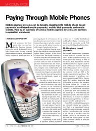
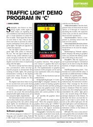
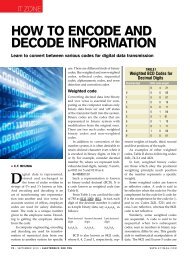
Fig. 1: <strong>Automatic</strong> vehicle parking system<br />
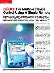
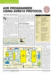
Fig. 2: Internal diagram of a typical <strong>RFID</strong> antenna<br />
or person for identification and tracking<br />
using radio waves. Some tags can<br />
be read from several metres away,<br />
beyond the line of sight of the reader.<br />
<strong>RFID</strong> technology is used in vehicle<br />
parking systems of malls and buildings<br />
(refer Fig. 1). The system normally<br />
consists of a vehicle counter, sensors,<br />
display board, gate controller, <strong>RFID</strong><br />
tags and <strong>RFID</strong> reader.<br />
Presented here is an automatic<br />
vehicle parking<br />
system using AT89S52<br />
microcontroller.<br />
<strong>RFID</strong> system<br />
fundamentals<br />
Basically, an <strong>RFID</strong> system<br />
consists of an antenna<br />
or coil, a transceiver<br />
(with decoder) and a<br />
transponder (RF tag) electronically<br />
programmed<br />
with unique information.<br />
There are many different<br />
types of <strong>RFID</strong> systems<br />
in the market. These are<br />
categorised on the basis<br />
of their frequency ranges.<br />
Some of the most commonly<br />
used <strong>RFID</strong> kits<br />
are low-frequency (30-<br />
500kHz), mid-frequency<br />
(900kHz-1500MHz) and<br />
high-frequency (2.4-<br />
2.5GHz).<br />
<strong>RFID</strong> antenna. Fig. 2<br />
shows the internal diagram<br />
of a typical <strong>RFID</strong><br />
antenna. The antenna<br />
emits radio signals to<br />
activate the tag and read/<br />
write data from/to it. It is<br />
the conduit between the<br />
tag and the transceiver,<br />
which controls the system’s<br />
data acquisition<br />
sani theo<br />
and communication.<br />
Antennae are available in a variety<br />
of shapes and sizes. These can be<br />
built into a door frame to receive tag<br />
data from persons or things passing<br />
through the door, or mounted on an<br />
inter-state tollbooth to monitor the<br />
traffic passing by on a freeway. The<br />
electromagnetic field produced by<br />
the antenna can be constantly present<br />
when multiple tags are expected continually.<br />
If constant interrogation is not<br />
required, a sensor device can activate<br />
the field.<br />
Often the antenna is packaged<br />
with a transceiver and decoder to act<br />
as a reader (interrogator), which can<br />
be configured either as a handheld<br />
or a fixed-mount device. The reader<br />
emits radio waves in the range of 2.5<br />
cm to 30 metres or more, depending<br />
upon its power output and the radio<br />
frequency used. When an <strong>RFID</strong> tag<br />
passes through the electromagnetic<br />
zone, it detects the reader’s activation<br />
signal. The reader decodes the data<br />
encoded in the tag’s integrated circuit<br />
(silicon chip) and communicates to the<br />
host computer for processing.<br />
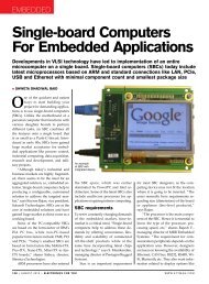
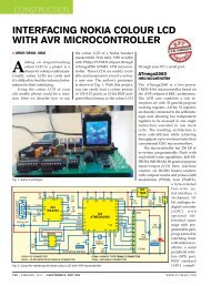
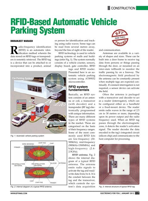
Fig. 3: Internal structure of typical <strong>RFID</strong> tag<br />
www.efymag.com Electronics For You | January 2012 117
construction<br />
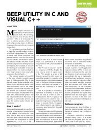
Fig. 4: Block diagram of <strong>RFID</strong>-based automatic vehicle parking system<br />
Tags (transponders). Fig. 3 shows<br />
the internal structure of a typical <strong>RFID</strong><br />
tag. It comprises a microchip containing<br />
identifying information about the<br />
item and an antenna that transmits<br />
this data wirelessly to the reader. At<br />
its most basic, the chip contains a serialised<br />
identifier or licence plate number<br />
that uniquely identifies that item<br />
(similar to bar codes). A key difference,<br />
however, is that <strong>RFID</strong> tags have<br />
a higher data capacity than their bar<br />
code counterparts. This increases the<br />
options for the type of information that<br />
can be encoded on the tag; it may include<br />
the manufacturer’s name, batch<br />
or lot number, weight, ownership,<br />
destination and history (such as the<br />
temperature range to which an item<br />
has been exposed). In fact, an unlimited<br />
list of other types of information<br />
can be stored on <strong>RFID</strong> tags, depending<br />
on the application’s requirements.<br />
<strong>RFID</strong> tag can be placed on individual<br />
items, cases or pallets for identification<br />
purposes, as well as fixed assets<br />
such as trailers, containers and totes.<br />
There are different types of tags with<br />
varying capabilities:<br />
1. Read-only tags contain such data<br />
as a serialised tracking number, which<br />
is pre-written onto these by the tag<br />
manufacturer or distributor. These are<br />
generally the least expensive tags as no<br />
additional information can be included<br />
when they move through the supply<br />
chain. Any update to the information<br />
has to be maintained in the application<br />
software that tracks the stock-keeping<br />
unit’s movement and activity.<br />
2. Write-once tags enable the user<br />
to write data once in the production<br />
or distribution<br />
process. The<br />
data may include<br />
a serial<br />
number or lot<br />
or batch number.<br />
3. Full<br />
read-write<br />
tags allow<br />
new data to<br />
be written to<br />
the tag—even<br />
over the original data—when needed.<br />
Examples include the time and date<br />
of ownership transfer or updating the<br />
repair history of a fixed asset. While<br />
these are the most costly of the three<br />
tag types and impractical for tracking<br />
inexpensive items, future standards for<br />
electronic product codes (EPCs) appear<br />
to be headed in this direction.<br />
Other features of the tag include:<br />
Data capacity. The capacity of data<br />
storage on a tag can vary from 16 bits<br />
to several thousand bits. Of course, the<br />
greater the storage capacity, the higher<br />
the price of the tag.<br />
Form factor. The tag and antenna<br />
structure can come in a variety of<br />
physical form factors and can either be<br />
self-contained or embedded as part of<br />
a traditional label structure (termed as<br />
‘smart label,’ it has the tag inside what<br />
looks like a regular bar code label).<br />
Passive and active. Passive tags have<br />
no battery and broadcast their data<br />
only when energised by a reader. It<br />
means these must be actively polled to<br />
send information. Active tags broadcast<br />
data using their battery power.<br />
This means their read range is greater<br />
than passive tags—around 30 metres<br />
or more, versus 5 metres or less for<br />
most passive tags.<br />
The extra capability and read range<br />
of active tags, however, come at a cost.<br />
These are several times more expensive<br />
than passive tags. Today, active tags<br />
are much more likely to be used for<br />
high-value items or fixed assets such<br />
as trailers, where the cost is minimal<br />
compared to item value and very<br />
long read ranges are required. Most<br />
traditional supply chain applications,<br />
such as the <strong>RFID</strong>-based tracking and<br />
compliance programmes emerging in<br />
the consumer goods retail chain, use<br />
the less expensive passive tags.<br />
Frequency range. Like all wireless<br />
communications, there are a variety of<br />
frequencies or spectra through which<br />
<strong>RFID</strong> tags communicate with readers.<br />
Again, there are trade-offs among cost,<br />
performance and application requirements.<br />
For instance, low-frequency<br />
tags are cheaper than ultra-highfrequency<br />
(UHF) tags, use less power<br />
and are better able to penetrate nonmetallic<br />
substances. These are ideal<br />
for scanning objects with high water<br />
content, such as fruit, at close ranges.<br />
UHFs typically offer longer range<br />
and can transfer data faster. But these<br />
use more power and are less likely to<br />
be effective with some materials.<br />
Electronic product code (EPC) tags.<br />
EPC is an emerging specification<br />
for <strong>RFID</strong> tags, readers and business<br />
applications. It represents a specific<br />
approach to item identification, including<br />
an emerging standard for the<br />
tags—with both the data content of the<br />
tag and open wireless communication<br />
protocols.<br />
RF transceiver. RF transceiver is<br />
the source of RF energy used to activate<br />
and power the passive <strong>RFID</strong> tags.<br />
It may be enclosed in the same cabinet<br />
as the reader or it may be a separate<br />
piece of equipment. When provided<br />
as a separate piece of equipment, the<br />
transceiver is commonly referred to as<br />
an RF module. RF transceiver controls<br />
and modulates the radio frequencies<br />
that the antenna transmits and<br />
receives. The transceiver filters and<br />
amplifies the backscatter signal from a<br />
passive <strong>RFID</strong> tag.<br />
How this vehicle parking<br />
system works<br />
Fig. 4 shows the block diagram of the<br />
<strong>RFID</strong>-based automatic vehicle parking<br />
system.<br />
To get started with <strong>RFID</strong>-based<br />
automatic vehicle parking system,<br />
the vehicle owner has to first register<br />
the vehicle with the parking owner<br />
and get the <strong>RFID</strong> tag. When the car<br />
118 January 2012 | Electronics For You www.efymag.com
construction<br />
Fig. 5: Circuit of the automatic <strong>RFID</strong>-based automatic vehicle parking system<br />
has to be parked, the <strong>RFID</strong> tag is<br />
placed near the <strong>RFID</strong> reader, which<br />
is installed near the entry gate of<br />
the parking lot. As soon as the <strong>RFID</strong><br />
tag is read by the reader, the system<br />
automatically deducts the specified<br />
amount from the <strong>RFID</strong> tag and the<br />
entry gate boomer opens to allow the<br />
car inside the parking area. At the<br />
same time, the parking counter increments<br />
by one. Similarly, the door<br />
is opened at the exit gate and the<br />
parking counter decremented.<br />
The system also offers the facility to<br />
recharge the amount for each <strong>RFID</strong> tag.<br />
No manual processing is involved. In<br />
addition, the system provides security.<br />
Circuit description<br />
Fig. 5 shows the circuit of the <strong>RFID</strong>based<br />
automatic vehicle parking system.<br />
The circuit can be divided into<br />
different sections:<br />
Power supply. Connector CON1<br />
(refer Fig. 8), diodes D1 through D4,<br />
capacitor C1, and voltage regulator<br />
ICs 7805 (IC1) and 7812 (IC2) form the<br />
power supply section of the automatic<br />
vehicle parking system. CON1 is a<br />
three-pin connector that provides 15V<br />
AC or DC power supply to the circuit.<br />
In case of 15V AC, diodes D1 through<br />
D4 form a bridge rectifier to rectify the<br />
AC supply. Capacitor C1 filters out<br />
the ripples from the rectified output.<br />
ICs 7805 and 7812 provide regulated<br />
+5V and +12V, respectively, to the<br />
circuit. +5V is used to operate the microcontroller,<br />
LCD, <strong>RFID</strong> and IR sensor<br />
circuit and +12V operates the motor.<br />
AT89S52 microcontroller.<br />
AT89S52 is a low-power, high-performance<br />
CMOS 8-bit microcontroller<br />
with 8kB Flash memory. It is compatible<br />
with the industry-standard<br />
80C51 instruction set and pin-out.<br />
The on-chip Flash allows the program<br />
memory to be reprogrammed<br />
in-system or by a conventional nonvolatile<br />
memory programmer. Other<br />
features include 256 bytes of RAM, 32<br />
input/output lines, watchdog timer,<br />
two data pointers, three 16-bit timers/counters,<br />
a six-vector two-level<br />
interrupt architecture, a full-duplex<br />
serial port, on-chip oscillator and<br />
clock circuitry.<br />
Connectors CON2 through CON4.<br />
CON2 and CON3 are two-pin connectors<br />
that connect the 12V DC motors<br />
to the circuit for controlling the entry<br />
and exit gate boomers. CON4 is a tenpin<br />
dual-in-line female connector that<br />
connects the <strong>RFID</strong> reader module to<br />
the circuit.<br />
L293D motor driver. H-bridge DC<br />
motor driver L293D (IC5) operates the<br />
DC motors to open the door or barrier<br />
for entry into and exit from the parking<br />
lot. Two high-current motor drivers<br />
can be used in place of L293D and 12V<br />
DC motors to control the entry and<br />
www.efymag.com Electronics For You | January 2012 119
construction<br />
Fig. 6: Pin details of<br />
7805, 7812 and BC547<br />
exit gates, respectively.<br />
LM358 opamp.<br />
Dual-operational<br />
amplifier<br />
LM358 (IC4)<br />
is used as a voltage<br />
comparator<br />
to compare the<br />
output of the IR sensors with a fixed<br />
threshold voltage in order to know<br />
whether the IR beam is interrupted<br />
or not.<br />
IR transmitter and receiver. Two<br />
IR transmitter-receiver pairs are<br />
used. The IR LEDs are connected<br />
in forward-biased condition to the<br />
+5V power supply through 220-ohm<br />
resistors. These emit IR light, which<br />
is interrupted when an object comes<br />
into its way to the IR receiver. The IR<br />
receiving photodiodes are connected<br />
in reverse-biased condition to +5V<br />
power supply through 1-mega-ohm<br />
resistors. When the IR light falls on<br />
the photodiodes, their resistance<br />
changes and so does their output.<br />
This output is compared with a fixed<br />
voltage to give a digital output to the<br />
microcontroller in order to judge the<br />
entry and exit of the vehicles.<br />
LCD display. LCD1 is a two-line,<br />
16-character, alpha-numeric liquid<br />
crystal display. Data lines D0 through<br />
D7 of the LCD are connected to port 2<br />
of AT89S52 (IC3). Reset (RS) and enable<br />
(E) control lines are connected to<br />
port pins P3.6 and P3.7, respectively.<br />
Control lines control data flow from<br />
the microcontroller to LCD1.<br />
When power is switched on,<br />
LED1 glows to indicate the presence<br />
of power in the circuit and LED2<br />
glows to indicate the presence of<br />
<strong>RFID</strong> reader. Simultaneously, the<br />
‘<strong>Automatic</strong> <strong>RFID</strong> Car <strong>Parking</strong>’ message<br />
is displayed on LCD1 along with<br />
a short beep from piezobuzzer PZ1.<br />
Transistor BC547 drives the buzzer.<br />
Pin details of 7805, 7812 and BC547<br />
are shown in Fig. 6.<br />
When a car crosses the IR LED1-<br />
D1 pair installed at the entry gate,<br />
the gate boomer does not open until<br />
an <strong>RFID</strong> tag is placed near the <strong>RFID</strong><br />
reader. After the tag is placed near the<br />
reader, the gate boomer opens for three<br />
seconds and closes automatically. If the<br />
initial recharge amount was Rs 900, the<br />
LCD display shows ‘<strong>Vehicle</strong>1 Amount’<br />
in the first line and ‘Deducted 100’ in<br />
the second line, followed by ‘Balance<br />
Amount’ in the first line and ‘800’ in<br />
Fig. 7: An actual-size, single-side PCB for the <strong>RFID</strong>-based automatic vehicle parking system<br />
Fig. 8: Component layout for the PCB<br />
120 January 2012 | Electronics For You www.efymag.com
the second line. It is then followed by<br />
display of ‘Number of Cars’ in the first<br />
line and ‘001’ in the second line. If the<br />
parking lot is full, the message “<strong>Parking</strong><br />
is Full, Sorry for Inconvenience” is<br />
displayed on LCD1.<br />
When a car leaves the parking<br />
area and crosses the IR beam between<br />
IR LED2 and D2 at the exit gate, the<br />
vehicle count decreases by one. The<br />
LCD shows the number of cars in the<br />
parking lot along with “Thanks for<br />
Visiting” message.<br />
Software<br />
The program (parking.c) for the microcontroller<br />
is written in C and compiled<br />
using Keil software to generate<br />
the hex code. The program coding<br />
starts with ‘#include’ and<br />
‘#include’ header files. The<br />
microcontroller port pins are defined<br />
using ‘sbit’ function for interfacing<br />
with the surrounding peripherals. The<br />
entry gate motor is controlled using<br />
‘sbit START_POINT=P1^3;’ code.<br />
The LCD is initialised using the<br />
following code:<br />
void lcdinit(void)<br />
{<br />
lcdcmd(0x38);<br />
DelayMs(250);<br />
lcdcmd(0x0E);<br />
DelayMs(250);<br />
lcdcmd(0x01);<br />
DelayMs(250);<br />
lcdcmd(0x06);<br />
//<strong>Automatic</strong> <strong>RFID</strong> <strong>Based</strong> <strong>Vehicle</strong> <strong>Parking</strong><br />
<strong>System</strong><br />
#include<br />
#include<br />
sbit START_POINT=P1^3;<br />
sbit TERMINATE_POINT=P1^4;<br />
sbit S1=P3^2;<br />
sbit S2=P3^3;<br />
sbit rc1=P1^1;<br />
sbit rc2=P1^2;<br />
sbit BUZZPORT=P1^7;<br />
sbit RS=P3^7;<br />
sbit EN=P3^6;<br />
void lcdinit();<br />
void lcdData(unsigned char l);<br />
void lcdcmd(unsigned char k);<br />
void buzzer(unsigned int time);<br />
void DelayMs(unsigned int count);<br />
DelayMs(250);<br />
lcdcmd(0x80);<br />
DelayMs(250);<br />
}<br />
Construction and testing<br />
An actual-size, single-side PCB layout<br />
for the <strong>RFID</strong>-based automatic vehicle<br />
parking system is shown in Fig. 7 and<br />
its component layout in Fig. 8. Burn<br />
the hex code into the AT89S52 microcontroller<br />
using a suitable programmer<br />
and then mount the microcontroller<br />
on the PCB. Install IR LED1-D1 pair at<br />
the entry gate such that these face each<br />
other. Similarly, install IR LED2-D2<br />
pair at the exit gate.<br />
For testing, switch on the circuit,<br />
interrupt the infrared beam between<br />
IR LED1 and IR D1 with your hand<br />
or some other opaque object and then<br />
remove it, and place the tag near the<br />
reader. The LCD should show the<br />
message as described earlier in ‘How<br />
this vehicle parking system works’<br />
section. An amount of Rs 100 should<br />
be deducted for every interruption of<br />
the IR beam. The card can be recharged<br />
by pressing the pushbutton switches<br />
(S2 and S3) provided in the circuit.<br />
Pressing switch S2 recharges the card<br />
with Rs 900 and pressing switch S3<br />
recharges it with Rs 500.<br />
Similarly, interrupt the IR beam<br />
at the exit gate. LCD1 should show<br />
the number of cars in the parking lot<br />
along with ‘Thanks for Visit’ message.<br />
void display(unsigned char s,t,u);<br />
void Welcome(unsigned char c[],unsigned<br />
char d[]);<br />
void ConvertAndDisplay(unsigned int<br />
value1,unsigned char c[]);<br />
void dcMotor();<br />
void main()<br />
{<br />
unsigned char i=0,j=0,result=0;<br />
unsigned int count;<br />
unsigned char c[15];<br />
unsigned char d[]=”42006B1BB8”;<br />
signed int amount2=900;<br />
TMOD=0x20;<br />
// To configure<br />
the serial port at 9600 baud rate<br />
TH1=0xFD;<br />
SCON=0X50;<br />
TR1=1;<br />
S1=1;<br />
S2=1;<br />
parking.C<br />
construction<br />
Parts List<br />
Semiconductors:<br />
IC1<br />
- 7805, 5V regulator<br />
IC2<br />
- 7812, 12V regulator<br />
IC3<br />
- AT89S52 microcontroller<br />
IC4<br />
- LM358 dual-operational<br />
amplifier<br />
<strong>RFID</strong> reader - 9-pin 125kHz <strong>RFID</strong> reader<br />
LED1, LED2 - 5mm light-emitting diode<br />
IR LED1,<br />
IR LED2 - 5mm infrared transmitter<br />
diode<br />
IRD1, IRD2 - 5mm infrared receiver diode<br />
D1-D4 - 1N4007 rectifier diode<br />
T1<br />
- BC547 transistor<br />
Resistors (all ¼-watt, ±5% carbon):<br />
R1<br />
- 470-ohm<br />
R4, R6, R8, R10 - 220-ohm<br />
R2, R9 - 10-kilo-ohm<br />
R3<br />
- 100-ohm<br />
R5, R7 - 1-mega-ohm<br />
VR1, VR2 - 100-kilo-ohm preset<br />
VR3<br />
- 10-kilo-ohm preset<br />
Capacitors:<br />
C1<br />
- 1000µF, 35V electrolytic<br />
C2<br />
- 10µF, 16V electrolytic<br />
C3, C4 - 22pF ceramic<br />
C5<br />
- 0.1µF ceramic<br />
Miscellaneous:<br />
LCD1 - 16×2 LCD display module<br />
CON1 - DC connector<br />
CON2, CON3 - Two-pin berg strip male<br />
connector<br />
CON4 - 9-pin berg strip female<br />
connector<br />
PZ1<br />
- Piezobuzzer<br />
X TAL1<br />
- 11.0592MHz crystal<br />
S1-S3 - Tactile switch<br />
M1, M2 - DC motor<br />
No amount should be deducted at the<br />
time of exit.<br />
EFY note. The source code of this<br />
article is available on www.efymag.<br />
com website.<br />
The author is founder and CEO of HBeonLabs,<br />
Greater Noida<br />
BUZZPORT=0;<br />
START_POINT=0;<br />
TERMINATE_POINT=0;<br />
lcdinit();<br />
Welcome(“AUTOMATIC <strong>RFID</strong>”,”CAR PARKING”);<br />
DelayMs(1000);<br />
while(1)<br />
{<br />
known:<br />
while(S1==1 && S2==1);<br />
if(S2==0)<br />
{<br />
while(S2==0);<br />
if(count>0)<br />
{<br />
count--;<br />
ConvertAndDisplay(count,”Thanks for Visit”);<br />
www.efymag.com Electronics For You | January 2012 121
construction<br />
}<br />
DelayMs(1000);<br />
goto known;<br />
else<br />
{<br />
count=0;<br />
ConvertAndDisplay(count,”Thanks<br />
Visit”);<br />
DelayMs(1000);<br />
goto known;<br />
}<br />
}<br />
if(S1==0)<br />
{<br />
while(S1==0);<br />
for(i=0;i