Download - Evapco
Download - Evapco
Download - Evapco

Create successful ePaper yourself
Turn your PDF publications into a flip-book with our unique Google optimized e-Paper software.
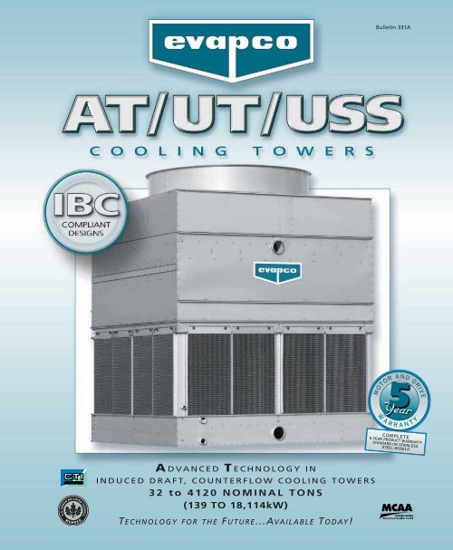
Bulletin 331A<br />
A DVANCED T ECHNOLOGY IN<br />
INDUCED DRAFT, COUNTERFLOW COOLING TOWERS<br />
32 to 4120 NOMINAL TONS<br />
(139 TO 18,114kW)<br />
T ECHNOLOGY FOR THE F UTURE...AVAILABLE T ODAY!
THE ADVANCED TECHNOLOGY DESIGN PROVIDING<br />
EVAPCO, Inc., continues its dedication<br />
to advancements in induced draft,<br />
counterflow cooling tower technology<br />
and easy maintenance with the<br />
Advanced Technology Cooling Tower...The EVAPCO AT!<br />
The AT is the result of decades of engineering success based<br />
on easy maintenance, durable construction and a highly<br />
efficient design. The AT brings marquee features that make<br />
it the better choice in cooling towers. These features are<br />
presented in this exclusive AT Marketing brochure.<br />
†<br />
Since its founding in 1976,<br />
EVAPCO, Inc. has become<br />
a world-wide leader in supplying<br />
quality cooling equipment<br />
for thousands of customers in<br />
both the commercial and industrial<br />
markets.<br />
EVAPCO’s success has been the result<br />
of a continual commitment to<br />
product improvement, quality<br />
workmanship and a dedication to<br />
providing unparalleled service.<br />
Our emphasis on research and development<br />
has led to many product<br />
innovations – a hallmark of<br />
EVAPCO through the years.<br />
The ongoing R & D Program enables<br />
EVAPCO to provide the most<br />
advanced products in the industry<br />
– technology for the future, available<br />
today.<br />
With 16 facilities in seven countries<br />
and over 170 sales offices in<br />
42 countries world-wide, EVAPCO<br />
is ready to assist in all your equipment<br />
needs.<br />
©2008 EVAPCO, INC.<br />
EVAPCO Power-Band Drive System<br />
• The AT Cooling Tower features the highly successful, easy<br />
maintenance, heavy duty Power-Band Drive System.<br />
• Standard heavy-duty pillow block bearings with a minimum<br />
L10 life of 75,000 hours.<br />
• Extended lube lines.<br />
• External motor/belt adjustment.<br />
• Aluminum Alloy Sheaves, Solid-Back Multi-Groove Power-Band<br />
Belts and Totally Enclosed motors are standard.<br />
• Five (5) Year Motor and Drive Warranty.<br />
EVAPCOAT Corrosion Protection System<br />
Totally Enclosed Fan Motors<br />
• Motors positioned for external access.<br />
• Assures long life.<br />
• Motor location allows for easy accessibility<br />
and serviceability.<br />
• Five (5) Year motor warranty.<br />
• G-235 Galvanized Steel Construction and Stainless Steel Strainers–EVAPCO set the<br />
standard with 2.35oz. of zinc per square foot of surface area.<br />
• Another EVAPCO standard–the stainless steel suction strainer eliminates excessive<br />
wear and corrosion.<br />
• Non-corrosive PVC Water Distribution System, Drift Eliminators and Inlet Louvers.<br />
• This system provides maximum corrosion protection as standard.<br />
2<br />
NEW!<br />
Louver Access Door<br />
• Hinged access panel with quick<br />
release mechanism<br />
• Allows easy access to perform<br />
routine maintenance and inspection<br />
of the makeup assembly,<br />
strainer screen and basin<br />
• Available on models with 5 ft.<br />
and 6 ft. tall louver sizes<br />
NEW!<br />
Easy Field Assembly<br />
• A new field assembly seam design<br />
which ensures easier assembly and<br />
reduced potential for field seam leaks<br />
• Self-guided channels guide the fan<br />
casing section into position improving<br />
the quality of the field seam<br />
• Eliminates up to 66% of fasteners<br />
† Mark owned by the Cooling Technology Institute
E ASIER S OLUTIONS AND B ETTER C HOICES<br />
Available in 55 Cross Sections and a capacity range of 32 to 4120 Nominal<br />
Tons (139 to 18,114 kW)! The AT has a model for every application.<br />
If there is an application for which the standard catalog product line does not work, EVAPCO will make a<br />
cooling tower that will fit your requirement! Consult your local EVAPCO Representative or the factory for<br />
all your cooling tower needs.<br />
CTI Certified-Standard 201<br />
• Independent Certification.<br />
• Eliminates necessity for costly field<br />
performance tests.<br />
Optional Motor Davit and Working Platform<br />
Motor Davit<br />
• Motor davit and bracket option for easy motor removal.<br />
• Also available for Gearbox removal.<br />
Platform<br />
• Platform and ladder arrangement available as an option.<br />
• Provides additional working surface for the service mechanic.<br />
Smooth Flow Fan<br />
• Soft-connect blade to<br />
hub design.<br />
• VFD-friendly<br />
• Eliminates critical blade passing<br />
frequencies at any speed.<br />
(Not available on 4 ft. wide models)<br />
Exclusive 5 Year Motor<br />
& Drive Warranty<br />
• Covers the complete drive<br />
system, including the motor.<br />
• Covers all drive components on<br />
belt or gear drive units.<br />
• Standard on all AT Models.<br />
• Upgraded 5 year Complete<br />
Product warranty on models<br />
with optional stainless steel<br />
construction.<br />
AT<br />
EVAPCO unequivocally<br />
guarantees the thermal<br />
performance of the AT<br />
cooling tower product line.<br />
NEW! EvapJet Nozzle<br />
Water Distribution System<br />
• Non-corrosive PVC construction with new EvapJet <br />
nozzles.<br />
• Large orifice nozzles prevent clogging and are<br />
threaded for easy removal and positive positioning.<br />
• 66% fewer nozzles!<br />
• System branches have threaded end caps to assist<br />
with debris removal.<br />
Clean Pan Sloped<br />
Basin Design<br />
Quick Connect Piping System<br />
• All inlet and outlet piping connections are<br />
beveled for welding and grooved to accept<br />
a mechanical coupling device as standard.<br />
• Facilitates easy pipe connections for quick<br />
installation.<br />
• Flanged connections are available as an<br />
option. (See page 10 Optional Equipment)<br />
• Designed to<br />
completely drain the<br />
cold water basin.<br />
• Helps prevent buildup<br />
of sediment and<br />
biological film.<br />
• Eliminates standing<br />
water after drain<br />
down.<br />
(See details of<br />
design on page 6)<br />
3
E ASY S OLUTIONS, BETTER C HOICES!<br />
D ESIGN A DVANTAGES<br />
The Advanced Technology Design<br />
The AT Cooling Tower product line is an Advanced Technology design which utilizes induced draft, counterflow technology–the<br />
most efficient in the industry and the best design for operation in a freezing climate. The counterflow design provides the AT<br />
Cooling Tower with inherently better operational and maintenance features. These features are described below.<br />
Cool Dry<br />
Entering Air<br />
Hot Saturated Discharge Air<br />
Air Intake<br />
Splashout<br />
Hot Water In<br />
Cooled<br />
Water Out<br />
Sunlight<br />
Debris<br />
Principle of Operation<br />
Warm water from the heat source is pumped to the water distribution system<br />
at the top of the tower. The water is distributed over the wet deck fill by<br />
means of large orifice nozzles. Simultaneously, air is drawn in through the air<br />
inlet louvers at the base of the tower and travels upward through the wet<br />
deck fill opposite the water flow. A small portion of the water is evaporated<br />
which removes the heat from the remaining water. The warm moist air is<br />
drawn to the top of the cooling tower by the fan and discharged to the atmosphere.<br />
The cooled water drains to the basin at the bottom of the tower<br />
and is returned to the heat source.<br />
The vertical air discharge of the AT design and the distance between the<br />
discharge air and fresh air intakes, reduces the chance of air recirculation,<br />
since the warm humid air is directed up and away from the unit. For detailed<br />
layout information please consult EVAPCO’s Equipment Layout Guidelines Bulletin<br />
311.<br />
Patented * Efficient Drift Eliminators<br />
An extremely efficient drift eliminator system is standard on the AT Cooling<br />
Tower. The system removes entrained water droplets from the air stream to<br />
limit the drift rate to less than 0.001% of the recirculating water rate.<br />
With a low drift rate, the AT Cooling Tower saves valuable water and water<br />
treatment chemicals. The AT can be located in areas where minimum water<br />
carryover is critical, such as parking lots.<br />
The drift eliminators are constructed of an inert polyvinyl chloride (PVC) plastic<br />
material which effectively eliminates corrosion of these vital components.<br />
They are assembled in sections to facilitate easy removal for inspection of the<br />
water distribution system.<br />
Patented ** EVAPAK ® Fill<br />
The patented EVAPAK ® fill design used in the AT Cooling Tower is specially designed<br />
to induce highly turbulent mixing of the air and water for superior heat<br />
transfer. Special drainage tips allow high water loadings without excessive pressure<br />
drop. The fill is constructed of inert polyvinyl chloride, (PVC), will not rot or<br />
decay, and is formulated to withstand water temperatures of 130˚F (55˚C). Because<br />
of the unique way in which the crossfluted sheets are bonded together,<br />
and the bottom support of the fill section, the structural integrity of the fill is<br />
greatly enhanced, making the fill usable as a working platform.<br />
The fill selected for the AT Cooling Tower has excellent fire resistant qualities.<br />
AT Cooling Tower fill has a flame spread rating of 5 per ASTM-E84-81a.<br />
A higher temperature fill is available for water temperatures exceeding<br />
130˚F (55˚C). Consult your EVAPCO representative for further details.<br />
Superior Air Inlet Louver and Screen Design<br />
The air inlet louver screens on the AT are constructed of corrosion-free PVC.<br />
They are a bi-planar design that eliminates splashout and reduces the potential<br />
for algae formation inside the tower.<br />
In uni-planar louver systems used by other manufacturers, circulating water<br />
droplets tend to splashout, especially when the fans are shut off. With the exclusive<br />
EVAPCO bi-planar louver system, the water droplets are captured on the<br />
inward sloping pass, eliminating splashout and the problems associated with it.<br />
EVAPCO’s patented louver design completely encloses the basin area. In addition<br />
to eliminating splash out, EVAPCO’s inlet louver screens are of a ‘Sight<br />
Tight’ design. Direct sunlight is blocked from the water inside the cooling<br />
tower, thereby reducing the potential of algae formation. Water treatment<br />
and maintenance costs are substantially reduced.<br />
While effectively containing the recirculating water and blocking sunlight, the<br />
louver design has a low pressure drop. The low pressure drop results in lower fan<br />
energy consumption, which reduces the operating costs of the cooling tower.<br />
* U.S. Patent No. 631580481 ** U.S. Patent No. 5124087<br />
4
E ASY S OLUTIONS, BETTER C HOICES!<br />
D ESIGN A DVANTAGES<br />
Reduced Piping Costs<br />
Each cell of the AT Cooling Tower is furnished with one inlet and<br />
one outlet piping connection. This design reduces the amount of<br />
external piping and thereby lowers the installed cost of the cooling<br />
tower. The water distribution system is pressurized and self balancing.<br />
Since field balancing is not required on the AT, the need for<br />
flow balancing valves is eliminated, further reducing the cost of<br />
tower installation. The wide orifice nozzles with anti-sludge ring<br />
used in the AT water distribution system helps prevent clogging, reducing<br />
the maintenance costs of the water distribution system.<br />
Pressurized Water Distribution System<br />
The water distribution system is made of schedule 40 PVC pipe and<br />
EvapJet ABS plastic water diffusers for corrosion protection in this<br />
key area. The piping is easily removable for cleaning. The water<br />
diffusers have a 1 inch diameter (25mm) opening and are practically<br />
impossible to clog. They also have an anti-sludge ring extending<br />
into the headers to prevent<br />
sediment from building up in the<br />
diffuser opening. In addition, the<br />
spray branches have threaded end<br />
caps to allow easy debris removal.<br />
The spray pressure for all AT Cooling<br />
Towers is between 1 and 6 psig (7<br />
and 42 kPa) at the inlet header. The<br />
New EvapJet nozzle compared<br />
to previous EVAPCO nozzles<br />
actual spray pressure will be shown<br />
on the certified drawings which are<br />
prepared for each unit.<br />
Optimum Design for Freezing Climates<br />
The counterflow fill design used in the AT Cooling Tower is well<br />
suited for winter operation. The wet deck surface is totally encased,<br />
and protected from freezing winds thus inhibiting ice formation<br />
on the fill section.<br />
The even temperature gradient of the counterflow fill design<br />
makes the AT Cooling Tower the ideal unit for operation in freezing<br />
climates.<br />
The counterflow design of the AT Cooling Tower fill section reduces<br />
the chance of ice formation and with bottom support, eliminates<br />
fill collapse should ice form.<br />
Fast, On-Time Shipments<br />
The AT is a completely factory assembled cooling tower manufactured<br />
by a dedicated professional workforce, expert in building<br />
cooling towers. Factory trained mechanics and EVAPCO’s strict<br />
quality control and inspection procedures guarantee the quality of<br />
every unit shipped.<br />
EVAPCO’s controlled factory environment ensures fast on-time shipments,<br />
allowing the AT to be available WHEN THE CUSTOMER<br />
WANTS IT!<br />
5
E ASY S OLUTIONS, BETTER C HOICES!<br />
M AINTENANCE A DVANTAGES<br />
The Advanced Technology Easy Maintenance Basin Design<br />
The cold water basin is the most important area of a cooling tower to maintain. As a result of the evaporation process in a<br />
cooling tower, dirt and debris will collect in the basin and must be cleaned out on a regular basis. EVAPCO’s AT basin section is<br />
designed to allow quick and easy access—promoting maintenance of the cold water basin. The basin features the following:<br />
Easy Access<br />
The cold water basin section is easily accessible from ground level by simply<br />
loosening the (2) two Quick Release Fasteners on the inlet louver assemblies<br />
surrounding the cooling tower and lifting out the lightweight louver.<br />
The basin can be accessed from all (4) four sides of the cooling tower. The<br />
bottom of the fill section is a minimum of four (4) feet (1.2m) above the<br />
basin floor. This open basin design enables the AT basin to be easily cleaned.<br />
Louver Access Door (optional)<br />
To aid in basin maintenance, all AT models can be equipped with an<br />
optional louver access door. This feature allows easy access to perform<br />
routine maintenance and inspection of the makeup assembly, strainer<br />
screen and basin without removing an entire inlet louver. The louver<br />
access door is standard on models with 5 and 6 ft. tall louver sizes.<br />
Easy, Removable Air Inlet Louvers with Quick<br />
Release Fasteners<br />
The AT features a Quick Release Fastener design consisting of (2) two large<br />
thumbscrews and a retaining bracket system. By loosening the thumbscrews,<br />
the retaining bracket lifts away from the louver frame, allowing<br />
the louver to be removed while the retaining bracket and thumbscrews stay<br />
on the cooling tower.<br />
• Design allows quick removal of louvers.<br />
• Louver fastener is large and easy to release.<br />
• Louver fastener remains on the unit–eliminating the possibility of<br />
missing hardware.<br />
Clean Pan Basin Design<br />
The AT features a completely sloped basin from the upper to lower pan section.<br />
This “Clean Pan” design allows the water to be completely drained<br />
from the basin. The cooling tower water will drain from the upper section<br />
to the depressed lower pan section where the dirt and debris can be easily<br />
flushed out through the drain. This design helps prevent buildup of sedimentary<br />
deposits, biological films and minimizes standing water.<br />
Note: on 4' wide units, the pan is sloped without the step<br />
Stainless Steel Strainers<br />
The EVAPCO standard for many years, the stainless steel strainer is one<br />
component of the cooling tower subject to excessive wear and corrosion.<br />
With stainless steel construction, this component will last the life of the<br />
cooling tower.<br />
6
E ASY S OLUTIONS, BETTER C HOICES!<br />
M AINTENANCE A DVANTAGES<br />
The Advanced Technology Easy Maintenance Drive System<br />
The EVAPCO POWER-BAND drive system utilized on the AT Cooling Tower is the easiest drive system to maintain in<br />
the industry. There is no need to stand inside the cold water basin to service the bearings, belts, gear reducers, floating<br />
shafts or electrical equipment. In addition, there is no need for fan deck handrails or safety cages, since all periodic maintenance<br />
can be safely performed from the side of the AT. The most important features of this design are listed below.<br />
Models AT 19-56 through AT 39-942<br />
Motor Mount, Power Band Belt Adjustment and Bearing Lubrication<br />
The fan motor and drive assembly are designed to allow easy servicing of the motor and adjustment of the belt tension from<br />
the exterior of the unit. The T.E.F.C. fan motor is mounted on the outside on these models and is protected from the weather<br />
by a cover which swings away for maintenance.<br />
A large hinged access door is located on the side of the unit for easy access to the fan drive system. The belt can be adjusted<br />
by tightening the J-Bolts on the motor base and the tension can be checked easily through the access door, all while standing<br />
at the side of the unit. The<br />
bearings can also be lubricated<br />
from the side of the<br />
unit. The bearing lubrication<br />
lines have been extended to<br />
the exterior casing and are<br />
located by the access door,<br />
thus making bearing lubrication<br />
easy.<br />
Sloped access ladders and<br />
working platforms are<br />
available as an option to<br />
facilitate maintenance.<br />
See page 9 Optional<br />
Equipment for details.<br />
Models AT 110-112 through AT 428-1248<br />
Motor Mount, Power Band Belt Adjustment and Bearing Lubrication<br />
The T.E.A.O. fan motor is located inside the fan casing on the large AT<br />
Cooling Tower, and is mounted on a rugged heavy duty motor base. The<br />
motor base is designed to swing completely to the outside of the unit<br />
through a very large hinged (14 square feet) (1.3 square meters) access<br />
door greatly simplifying motor maintenance.<br />
The unique swinging motor mount designed for these models features<br />
easy belt adjustment from the exterior of the unit. The T.E.A.O. fan<br />
motor is mounted on an adjustable base which is supported by two heavy<br />
duty galvanized steel pipes. The belt is adjusted by tightening an allthread<br />
which runs through the motor base.<br />
The innovative motor base features a unique locking mechanism for a<br />
positive belt adjustment and is also used to adjust the belt tension if a<br />
wrench is not available.<br />
Bearing lubrication fittings are extended<br />
to the side of the unit inside the access<br />
door to allow easy application of the bearing<br />
lubricant. This external location allows<br />
for easy servicing of the bearings and<br />
is another important advantage of<br />
EVAPCO equipment.<br />
To facilitate motor removal, an optional<br />
motor davit is available. See Optional<br />
Equipment page 9 of this brochure.<br />
7
E ASY S OLUTIONS, BETTER C HOICES!<br />
D RIVE S YSTEM D ESIGN<br />
The Advanced Technology POWER-BAND Drive System Design<br />
The AT Cooling Tower features the highly successful EVAPCO POWER-BAND Belt Drive System engineered for heavy-duty operation.<br />
The POWER-BAND Drive System has consistently provided trouble-free operation in the most severe duty cooling tower applications.<br />
In addition, the complete drive system including the fan motor is standard with a (5) Five Year Motor & Drive Warranty.<br />
Fan Motors<br />
All AT Cooling Tower models utilize heavy duty totally enclosed (T.E.F.C. or<br />
T.E.A.O.) fan motors designed specifically for cooling tower applications. In<br />
addition to the standard motors offered on each cooling tower, EVAPCO offers<br />
many optional motors to meet your specific needs, including:<br />
• Premium Efficiency Motors<br />
• Multi-Speed Motors<br />
• Inverter-Duty Motors for VFD Applications<br />
Models AT 14-64 through 14-912 have a direct drive fan system. The T.E.A.O.<br />
motor is located inside the cooling tower.<br />
The T.E.F.C. motors are located on the outside of the unit on Models AT<br />
19-56 through AT 39-942 and are protected by a hinged, swing away cover.<br />
Models AT 110-112 through 428-1248 have T.E.A.O. motors located inside the<br />
fan section on a heavy duty motor base which swings to the outside for repair<br />
or removal.<br />
On Models AT 14-64 through 14-912<br />
On Models AT 19-56 through 39-942<br />
On Models AT 110-112 through 428-1248<br />
Power-Band Belt Drive<br />
The Power-Band drive is a solid-back multigroove belt system that has<br />
high lateral rigidity. The belt is designed for cooling tower service, and is<br />
constructed of neoprene with polyester cords. The drive belt is sized for<br />
150 percent of the motor nameplate horsepower ensuring long and<br />
trouble free operation.<br />
Drive System Sheaves<br />
Drive system sheaves located in the warm, moist atmosphere inside the<br />
cooling tower are constructed of an aluminum alloy. Those located<br />
externally are protected by a hinged protective cover.<br />
Fan Shaft Bearings<br />
The fan shaft bearings on the AT cooling tower are specially selected to<br />
provide long life, minimizing costly downtime. They are rated for an L-10<br />
life of 75,000 to 135,000 hours, making them the heaviest duty pillow<br />
block bearing in the industry used for cooling tower duty.<br />
Five Year Motor and Drive Warranty<br />
EVAPCO provides a standard 5 year motor and drive warranty on all<br />
Power-Band belt drive and optional gear drive AT Cooling Towers. This<br />
unique warranty is designed to offer the end user optimum protection<br />
against fan drive and motor failure. It is a comprehensive plan which<br />
includes the fan, fan shaft, belts, sheaves, fan bearings, gear box, flexible<br />
coupling, driveshaft and the motor.<br />
8
E ASY S OLUTIONS, BETTER C HOICES!<br />
O PTIONAL E QUIPMENT<br />
Optional Equipment<br />
The standard design of the EVAPCO AT provides the customer with the easiest cooling tower to maintain in the industry.<br />
There are additional options which can make maintenance easier and extend the life of the cooling tower. These options<br />
are listed below.<br />
Sloped Access Ladders<br />
The EVAPCO designed access ladder features a sloped “ships type”<br />
ladder arrangement which provides fast and easy access to the<br />
water distribution system and drive components. A handrail is attached<br />
to the sloped ladder for safe and easy ascent and descent.<br />
There is no need for safety cages with this design. The ladder(s)<br />
will ship loose and must be field mounted. Meets all applicable<br />
OSHA requirements.<br />
Note: The sloped access ladder is available on all models AT 19-56<br />
through AT 428-1248. A vertical ladder is available on models AT 14-<br />
64 through 14-912.<br />
Working Platform & Ladder with Davit<br />
AT Cooling Towers are available with an external working platform<br />
and ladder to allow easy servicing of the fan motor and water distribution<br />
system. Providing a convenient platform to perform<br />
work, the heavy duty galvanized steel platform is self-supportingwhich<br />
eliminates the need for any external support. A less expensive<br />
alternative to field erected catwalks, the working platform<br />
option uses a straight ladder as standard and ships in sections for<br />
easy installation. (The working platform and ladder meet all applicable<br />
OSHA requirements.)<br />
Note: The Working Platform is not available on models AT 14-64<br />
through 14-912.<br />
The davit option eliminates crane rentals and facilitates the removal<br />
of motors and gear drives. The davit and bracket are constructed of<br />
aluminum and are mounted on the side of the unit. The optional<br />
fan motor and gear davit ships loose and is installed in the field.<br />
*Louver frame and support not in photo<br />
Stainless Steel Water Touch Basin<br />
The AT Cooling Tower has a modular design which allows specific<br />
areas to be enhanced for increased corrosion protection. The basin<br />
area of the cooling tower experiences turbulent mixing of air and<br />
water, in addition to silt build-up. In conjunction with the EVAP-<br />
COAT Corrosion Protection System, EVAPCO offers an optional Stainless<br />
Steel Water Touch Basin. This option provides Type 304 or Type<br />
316 stainless steel for the entire basin area including the support<br />
columns of the cooling tower and the louver frames.<br />
The basin section provides the structural support for the unit and is<br />
the most important part of the cooling tower. The Stainless Steel<br />
Water Touch Basin provides maximum corrosion protection.<br />
Basin Level Platform<br />
AT Cooling Towers are available on some box sizes with a basin level<br />
platform and ladder to allow easy servicing of the cold water basin.<br />
• Facilitates Maintenance<br />
- Adjust Float Assembly<br />
- Clean Basin and Suction Strainer<br />
• Self Supporting and Easy Installation<br />
- Platform Supported from Unit<br />
- Ladder Requires Field Support<br />
- Ships in Modules for Easy Installation<br />
9
E ASY S OLUTIONS, BETTER C HOICES!<br />
O PTIONAL E QUIPMENT<br />
Electric Heaters<br />
Electric immersion heaters are available as an option and are located in the<br />
basin of the tower. They are sized to maintain a +40° F (4.5°C) pan water<br />
temperature at 0°F (-18°C) ambient with the fans off*. They are furnished<br />
with a combination thermostat/low water protection device to cycle the<br />
heater on when required and to prevent the heater elements from energizing<br />
unless they are completely submerged. All components are enclosed in<br />
rugged, weather proof enclosures for outdoor use. Heater control packages<br />
that include contactor, transformer or disconnects are available, consult your<br />
local EVAPCO representative.<br />
(*) - Electric heater selection based on 0°F (-18°C) ambient temperature.<br />
For alternate low ambient heater selections, consult factory. Refer to the<br />
factory certified heater drawing for quantity and sizing of heaters.<br />
Electric Water Level Control<br />
EVAPCO cooling towers are available with an optional electric water level<br />
control system in place of the standard mechanical makeup valve and float<br />
assembly. This package provides very accurate control for the basin water<br />
level and does not require field adjustment, even under varying operating<br />
conditions.<br />
The control was designed by EVAPCO and is manufactured exclusively for<br />
EVAPCO. It consists of multiple heavy duty stainless steel electrodes. These<br />
electrodes are mounted external to the unit in a vertical stand pipe. For<br />
winter operation, the stand pipe must be wrapped with electric heating<br />
cable and insulated to protect it from freezing.<br />
The weather protected slow closing solenoid valve(s) for the makeup water<br />
connection is factory supplied and is ready for piping to a water supply with<br />
a pressure between 25 and 50 psig (172 and 345 kPa).<br />
Flanged Connections<br />
Bypass Connections with<br />
Diffuser Hood<br />
Equalizers and<br />
Flume Plates<br />
Other Options<br />
• Heater Control Packages<br />
• Hot Water or Steam Coils<br />
• Steam Injectors<br />
• Bottom Suction Connections<br />
• Vibration Isolators (single cell only)<br />
• Vibration Switches<br />
• Remote Sump Connections<br />
• Motors–Energy Efficient / Inverter Duty /<br />
2S/1W and 2S/2W / Mill and Chem Duty<br />
Automotive Duty and Many More,<br />
Consult the Factory<br />
Technical Support Services<br />
iES the internet Equipment Solution<br />
iES is a Web based computer selection program which allows<br />
the design engineer to choose EVAPCO models and optimize<br />
unit selections. The program allows the engineer to evaluate<br />
the equipment’s thermal performance, space and energy requirements.<br />
Once the model is selected and optional equipment<br />
features are inserted, the engineer may output a<br />
complete specification AND a unit drawing from this program.<br />
The software is designed to provide the user with maximum<br />
flexibility in analyzing the various selection parameters<br />
while in a friendly and familiar Windows format.<br />
The iES Equipment Selection Software program may be accessed<br />
using Microsoft Internet Explorer after contacting your<br />
local EVAPCO sales representative. Users may make Requests<br />
for Quotations through the website or by e-mailing EVAPCO<br />
at this address marketing@evapco.com<br />
EVAPCO’s Website<br />
Log on to EVAPCO’s new and improved website<br />
http://www.evapco.com. for expanded product information.<br />
Users can view and download unit certified and steel<br />
support drawings in a .pdf format readable using Adobe<br />
Acrobat. In addition, scaled isometric views of our equipment<br />
in CAD (.dwg format) are also available. Product literature,<br />
Rigging and Maintenance Instructions and EVAPCO<br />
logo apparel and merchandise are all accessible online from<br />
your computer.<br />
With the internet Equipment Solution program, equipment selections,<br />
written specifications, unit drawing files and EVAPCO<br />
on-line information are readily available from the comfort of<br />
your own office!<br />
10
E ASY S OLUTIONS, BETTER C HOICES!<br />
LOW SOUND SOLUTIONS<br />
The Expanded Family of the EVAPCO Super Low Sound Fans!<br />
Super Low Sound Fan 9 – 15 dB(A) Reduction!<br />
The Super Low Sound Fan offered by EVAPCO utilizes an extremely wide chord blade<br />
design available for sound sensitive applications where the lowest sound levels are<br />
desired. The fan is one-piece molded heavy duty FRP construction utilizing a forward<br />
swept blade design. The Super Low Sound fan is capable of reducing the unit sound<br />
pressure levels 9 dB(A) to 15 dB(A), depending on specific unit selection and measurement<br />
location compared to the original AT fan.<br />
Low Sound Fan* 4 – 7 dB(A) Reduction!<br />
The NEW Low Sound Fan offered by EVAPCO is a wide chord blade design for sound sensitive<br />
applications where low sound levels are desired. The Low Sound Fan shall utilize a<br />
unique soft-connect blade-to-hub design that is compatible with Variable Speed Drives.<br />
Since the blades are not rigidly connected to the fan hub, no vertical vibration forces are<br />
transmitted to the unit structure which totally eliminates sound pressure levels 4 dB(A) to<br />
7 dB(A), depending on specific unit selection and measurement location. The fans are<br />
high efficiency axial propeller type and are CTI Certified on the AT line of Cooling Towers.<br />
The Low Sound Fan is NOT available on the UT Cooling Tower.<br />
* The CTI Certified Low Sound Fan will have a thermal performance derate up to 3.5%.<br />
Consult the factory or iES Program for actual thermal performance.<br />
Fan Discharge Sound Attenuation – Up to 10 dB(A) Reduction!<br />
The discharge attenuator is a factory assembled straight sided discharge hood designed<br />
to reduce overall discharge sound levels at full fan speed 5 dB(A) to 10 dB(A), depending<br />
on specific unit selection and measurement location. It is constructed of G-235 galvanized<br />
steel as standard (options available for Type 304 stainless steel) and includes<br />
insulated walls and a low pressure drop baffling system that is acoustically lined with<br />
high density fiberglass. The discharge attenuator is supported entirely by the unit and is<br />
shipped as an assembled section for easy mounting in the field. The discharge attenuator<br />
is covered by a heavy gauge hot-dip galvanized steel fan guard to prevent debris<br />
from entering the attenuator.<br />
The discharge attenuator will have a minimal impact on unit thermal performance (0%-<br />
2% derate depending on specific unit selection).<br />
The discharge attenuator is available on 10 ft., 12 ft., 14 ft., 20 ft., 24 ft. and 28 ft. wide<br />
AT Models with the Low Sound Fan option.<br />
(Note: The Fan Discharge Attenuator Option is NOT available on UT or USS Models<br />
provided with the Super Low Sound Fan.)<br />
Water Silencer–Reduces Water Noise in the Cold Water Basin up to 7<br />
dB(A)!<br />
The water silencer option is available for all induced draft models and is located in the<br />
falling water area of the cold water basin. The water silencer will reduce the high frequency<br />
noise associated with the falling water and is capable of reducing overall sound<br />
levels 4 dB(A) to 7 dB(A) measured at 5 ft. from the side or end of the unit. The water<br />
silencers reduce overall sound levels 9 dB(A) to 12 dB(A) (depending on water loading<br />
and louver height) measured 5 ft. from the side or end of the unit when water is circulated<br />
with fans off.<br />
The water silencers are constructed of lightweight PVC sections and can be easily removed<br />
for access to the basin area. The water silencer will have no impact on unit thermal performance.<br />
Note: These items are not available for the AT/USS 14-64 through 14-912 cooling towers.<br />
11
E ASY S OLUTIONS, BETTER C HOICES!<br />
Notes:<br />
12
T ECHNOLOGY FOR THE F UTURE, AVAILABLE T ODAY!<br />
IBC COMPLIANCE<br />
We Stand Tall<br />
Through it All!<br />
The Internationaltional<br />
Building Code (IBC) is a<br />
comprehensive set of<br />
regulations addressing<br />
the structural ral design<br />
and installationtion<br />
requirements for<br />
building systems stems –<br />
including HVAC<br />
and industrial<br />
refrigeration<br />
equipment. .<br />
IBC<br />
COMPLIANCE<br />
With the advent<br />
of the IBC,<br />
EVAPCO is<br />
proud to<br />
introduce the new and<br />
improved line of AT, UT and USS<br />
Cooling Towers with IBC 2006<br />
compliance standard.<br />
Wind, Rain,<br />
Earthquake<br />
and Hurricane<br />
EVAPCO Cooling Towers…designed to<br />
withstand seismic or wind load forces.<br />
13
T ECHNOLOGY FOR THE F UTURE, AVAILABLE T ODAY!<br />
IBC COMPLIANCE<br />
In its continuing commitment to be the leader in evaporative cooling equipment design and<br />
services, EVAPCO AT Cooling Towers are now Independently Certified to withstand Seismic and<br />
Wind Loads in ALL Geographic Locations and Installations in accordance with IBC 2006.<br />
What is IBC?<br />
International Building Code<br />
The International Building Code (IBC) is a comprehensive<br />
set of regulations addressing both the structural design<br />
and the installation requirements for building systems –<br />
including HVAC and industrial refrigeration equipment.<br />
The IBC is intended to replace BOCA’s The National Building<br />
Code, ICBO’s Uniform Building Code and SBCCI’s Standard<br />
Building Code.<br />
Compared to previous building codes that considered<br />
only the building structure and component anchorage,<br />
the requirements contained within the IBC address anchorage,<br />
structural integrity, and the operational capability<br />
of a component following either a seismic or wind<br />
load event. Simply stated, the IBC code provisions require<br />
that evaporative cooling equipment, and all<br />
other components permanently installed on a<br />
structure, must be designed to meet the same seismic<br />
or wind load forces as the building to which<br />
they are attached.<br />
How Does IBC 2006 Apply to Cooling<br />
Towers?<br />
Based on the project zip code and site design factors, calculations<br />
are made to determine the equivalent seismic<br />
“g force” and wind load (in pounds per square foot – psf)<br />
on the unit. The cooling tower must be designed to withstand<br />
the greater of either the seismic or wind load.<br />
The New AT is offered with a choice of TWO structural<br />
design packages:<br />
• Standard Structural Design – For projects with<br />
1.0g seismic or 60 psf wind loads<br />
• Upgraded Structural Design – Required for<br />
projects with > 1.0 g seismic or 60 psf wind loads<br />
All locations with design criteria resulting in a seismic<br />
design force of up to 1.0g or a wind load of 60 psf or<br />
below will be provided with the standard AT structural<br />
design. An upgraded structural design is available for<br />
installations with design criteria resulting in “g forces”<br />
greater than 1.0g. The highest “g force” location in<br />
North America is 5.12g. The highest wind load shown<br />
on the maps is 170 mph, which is approximately equal to<br />
145 psf velocity pressure. Therefore, the upgraded<br />
structural design package option for the New AT is<br />
designed for 5.12 g and 145 psf making it applicable<br />
to ALL building locations in North America.<br />
Seismic Design<br />
The chart shown below, from the US Geological Survey<br />
Website http://www.usgs.gov/ shows the potential seismic<br />
activity in the United States. Buildings constructed in<br />
the red, orange and yellow areas of the map are most<br />
likely to require the upgraded AT construction design<br />
based on the site seismic design factors. Critical use facilities,<br />
such as hospitals, are also more likely to require the<br />
upgraded design.<br />
Map courtesy US Geological Survey website<br />
Highest Hazard<br />
32+<br />
24-32<br />
16-24<br />
%g 8-16<br />
4-8<br />
2-4<br />
0-2<br />
Lowest Hazard<br />
The project architect or civil engineer is responsible for<br />
determining the seismic design factors to be used for the<br />
building design. A mechanical consulting engineer and/or<br />
design build contractor will then apply these factors to a<br />
series of charts and graphs to determine the appropriate<br />
seismic design factors based on the location of the installation<br />
and ultimately the “importance” of the facility.<br />
The specific factors necessary for seismic design as well as<br />
a sample seismic calculation are shown on the next page.<br />
< –<br />
14
ID IBC COC 00<br />
T ECHNOLOGY FOR THE F UTURE, AVAILABLE T ODAY!<br />
IBC COMPLIANCE<br />
Wind Design<br />
The IBC 2006 code book includes a map of basic wind<br />
speed (3-second gust) by contour lines. However, local<br />
regulations may be more stringent than these published<br />
speeds. The specific factors necessary for wind load as<br />
well as a sample wind load calculation are shown on<br />
Page 16.<br />
Whichever design force - seismic or wind - is more severe<br />
for the building, governs the design of the building and<br />
all attached equipment.<br />
Certificate of Compliance<br />
AT, USS, UAT, UT Cooling Towers<br />
ATW Closed Circuit Coolers<br />
HTC,ATC-E Evaporative Condensers<br />
Are certified to meet or exceed the Seismic and Wind Load Provisions<br />
set forth in the applicable building codes for this project.<br />
These products have been manufactured following all<br />
applicable quality assurance programs.<br />
Applicable Building Codes:<br />
Referenced Report:<br />
IBC 2006<br />
VMA-43387<br />
ASCE-7<br />
NFPA 5000<br />
Approval Agency:<br />
VMC Seismic Consulting Group<br />
EVAPCO...Specialists<br />
in Heat Transfer Products and Services.<br />
1<br />
If the seismic “g force” or wind load psf requirements for<br />
the project site are known, EVAPCO’s online equipment<br />
selection software, iES, will allow you to choose the required<br />
structural design package – either standard construction<br />
or upgraded construction.<br />
If the project requirements are unknown, the following<br />
calculations must be completed.<br />
Wind Load Map Courtesy IBC 2006 Text –<br />
See full-sized map for location specific values<br />
Design Implementation<br />
EVAPCO applies the seismic design and wind load information<br />
provided for the project to determine the equipment<br />
design necessary to meet IBC requirements. This<br />
process ensures that the mechanical equipment and its<br />
components are compliant per the provisions of the IBC<br />
as given in the plans and specifications for the project.<br />
Independent Certification<br />
Although the IBC references and is based on the structural<br />
building code ASCE 7, many chapters and paragraphs<br />
of ASCE 7 are superceded by the IBC, independent<br />
certification and methods of analysis are such paragraphs.<br />
Per the most recent edition of the code, the EVAPCO<br />
compliance process included an intensive analysis by an<br />
independent approval agency. As required by the International<br />
Building Code, EVAPCO supplies a certificate of<br />
compliance as part of its submittal documents. The certificate<br />
of compliance demonstrates that the equipment has<br />
been independently tested and analyzed in accordance<br />
with the IBC seismic and wind load requirements. <strong>Evapco</strong><br />
has worked closely with the independent approval<br />
agency, The VMC Group, to complete the independent<br />
equipment testing and analysis.<br />
When using the EVAPCO selection software to make a<br />
selection, these calculations are already incorporated<br />
into the selection process. Simply enter the required<br />
factors and the Seismic Design Force and Wind Load<br />
will be calculated automatically!!<br />
For further questions regarding IBC compliance, please<br />
contact your local EVAPCO Representative or visit<br />
www.evapco.com.<br />
Seismic Load Calculations<br />
The data required to calculate the seismic load are:<br />
Occupancy Category – I, II, III or IV depending on the<br />
nature of the building occupancy. Table 1604.5 in the IBC<br />
2006 Code Book defines each of the four categories in detail.<br />
In summary the four categories are:<br />
• Category I - structures that represent a low hazard to<br />
human life in the event of a failure.<br />
• Category III - structures that represent a substantial<br />
hazard to human life in the event of a failure.<br />
• Category IV - structures designated as essential<br />
facilities.<br />
• Category II - any structures not listed in I, III or IV.<br />
Site Classification – A, B, C, D, E or F based on the types<br />
of soil and their engineering properties. Table 1613.5.2 in<br />
the IBC 2006 Code Book defines each of the categories in<br />
detail. IBC specifies site class “D” when soil properties are<br />
unknown.<br />
15
E ASY S OLUTIONS, BETTER C HOICES!<br />
IBC COMPLIANCE<br />
Maximum Spectral Response Acceleration (Ss) – Numerical<br />
value found using the U.S. Geological (USGS) data<br />
based on the Zip Code of the project. This data point can<br />
be determined using the Ground Motion Parameter Calculator<br />
at http://www.usgs.gov/. Note the calculator assumes<br />
a site classification of B for the 0.2 second<br />
maximum Ss. The site coefficient (Fa), defined below, will<br />
correct for the actual site classification.<br />
Site Coefficient (Fa) – Values ranging from 0.8 to 2.5 determined<br />
based on the Ss and the Site Classification. Table<br />
1613.5.3(1) in the IBC 2006 Code Book defines these values.<br />
Design Spectral Response Acceleration (SDS) – A calculated<br />
value using the values for Ss and Fa.<br />
Seismic Load Sample Calculation<br />
SDS<br />
= 2 (Fa)(Ss) = 2 (1.0)(1.495)=0.9966<br />
3 3<br />
SDS<br />
= 2 (Fa)(Ss)<br />
3<br />
Amplification Factor (ap) – 2.5 for flexible components<br />
or flexibly attached components. Due to its low inherent<br />
natural frequencies, most evaporative cooling equipment<br />
falls under the definition of flexible. Therefore the default<br />
for Cooling Towers is 2.5. See Table 13.6-1 in the<br />
American Society of Civil Engineers (ASCE) Standard 7-05,<br />
to which IBC often references, for more information.<br />
Response Modification Factor (Rp) – 2.5 for non-isolated<br />
evaporative cooling equipment. 2.0 for vibration<br />
isolated evaporative cooling equipment. Table 13-6.1 of<br />
ASCE 7-05 provides additional information.<br />
Component Operating Weight (Wp) – This weight<br />
term has been removed from the equation below, because<br />
EVAPCO is expressing the force in terms of g’s and<br />
not lbs.<br />
Importance Factor (Ip) – 1.5 for Occupancy Category IV,<br />
life safety components required to function after a seismic<br />
event or component containing hazardous content.<br />
1.0 for all other components. ASCE 7-05 Section 13.1.3<br />
provides additional detail on importance factors.<br />
Installation Location (Z/h) – 0 for units installed at<br />
ground level. 1.0 for units installed on a rooftop. Per<br />
ASCE 7-05 Section 13.3, z = the height of the point of attachment<br />
of the component and h = the relative roof<br />
height.<br />
Seismic Design Force, (Fp) – “G-force” that the unit<br />
must be able to withstand. This number is calculated<br />
using the factors described above. The New AT is offered<br />
with a choice of two structural design packages, consisting<br />
of:<br />
– Standard Structural Design ≤ 1.0g<br />
– Upgraded Structural Design – up to 5.12g (the<br />
maximum value for North America)<br />
The following example demonstrates the procedure for<br />
determining which structural design package a Community<br />
Hospital located in Charleston, SC (zip code 29401)<br />
would require under the latest version of IBC. In this example,<br />
the cooling tower will be installed on a roof, approximately<br />
60 feet above grade. The unit will also be<br />
installed with a vibration isolation system.<br />
Step 1: Calculate the Design Spectral Response Acceleration<br />
(SDS)<br />
Where:<br />
SS = 1.495; using the USGS Ground Motion Parameter<br />
Calculator<br />
Fa = 1.0; from Table 1613.5.3(1) in the IBC 2006 Code<br />
Book assuming a Site Classification of D<br />
FP<br />
0.4 (aP)(SDS)(WP)<br />
= 1+2 z =<br />
h<br />
RP<br />
( IP )<br />
( )<br />
Step 2: Calculate the Seismic Design Force (Fp )<br />
Where:<br />
ap = 2.5; the default for cooling towers and closed<br />
circuit coolers<br />
SDS = 0.9966; as calculated in Step 1<br />
Wp = 1.0; the default for cooling towers and closed<br />
circuit coolers<br />
Rp = 2.0; the default for isolated equipment<br />
I p = 1.5; the default for life safety components<br />
z/h = 1.0; the default for units on a rooftop<br />
In order to meet Code requirements, the unit and its anchorage<br />
must be constructed to withstand 2.24 g. This<br />
will require that the upgraded structure option be chosen<br />
to meet the seismic requirements of this project. Because<br />
the seismic load requires the upgraded structural design,<br />
the wind load calculation results will not change the design<br />
and are not required for this analysis.<br />
Wind Load Calculations<br />
0.4 (2.5)(0.9966)(1)<br />
2.0<br />
1.5 ( )<br />
The data required to calculate the wind load are:<br />
(1+2(1))=2.24g<br />
16
E ASY S OLUTIONS, BETTER C HOICES!<br />
IBC COMPLIANCE<br />
Basic Wind Speed (V) – Numerical value, in miles per<br />
hour (mph) found in ASCE 7-05 Figures 6-1 (A,B,C).<br />
Wind Directionality Factor (Kd) – 0.85 for building<br />
components and cladding. Table 6-4 of ASCE 7-05 provides<br />
additional information.<br />
Occupancy Category – I, II, III or IV depending on the<br />
nature of the building occupancy. Table 1604.5 in the IBC<br />
2006 Code Book defines each of the categories in detail.<br />
This is the same Occupancy Category used in Seismic calculations.<br />
Importance Factor (I) – Numerical value between 0.77<br />
and 1.15 based on the Basic Wind Speed and the Occupancy<br />
Category. These values are found in Table 6-1 of<br />
ASCE 7-05.<br />
Exposure Category – B, C or D as defined in Section<br />
6.5.6.3 of ASCE 7-05.<br />
Component Elevation (z) – The anchorage height of<br />
the unit in feet.<br />
Nominal Height of the Atmospheric Boundary Layer<br />
(zg) - Numerical value based on Exposure Category. These<br />
values are found in Table 6-2 of ASCE 7-05.<br />
3 second Gust-Speed power Law Exponent (α) - Numerical<br />
value based on Exposure Category. These values<br />
are found in Table 6-2 of ASCE 7-05.<br />
z<br />
KZ = 2.01( zg)<br />
2<br />
( a )<br />
Velocity Pressure Exposure Coefficient (Kz) – A calculated<br />
value using the values for zg and α.<br />
Topographic Factor (Kzt) – 1.0 default when topographic<br />
effects are not a factor. ASCE 7-05 Section 6.5.7<br />
provides additional detail on topographic factors.<br />
Velocity Pressure (qz) – This number in pounds per<br />
square foot (psf) is calculated using the factors described<br />
above. The New AT is offered with a choice of two structural<br />
design packages, consisting of:<br />
– Standard Structural Design - up to 60 psf<br />
– Upgraded Structural Design - up to 145 psf (the<br />
maximum value for North America)<br />
The following example demonstrates the procedure to<br />
determine which structural design package a Condominium<br />
Building located in Miami, FL (zip code 33101)<br />
would require under the latest version of IBC. In this example,<br />
the cooling tower will be installed on the top of<br />
KZ = 2.01<br />
( a )<br />
( )<br />
( 11.5)<br />
2 2<br />
z<br />
60<br />
=<br />
( zg) 2.01 =<br />
700<br />
1.31<br />
the 60 foot tall building.<br />
Step 1: Calculate the Exposure Category Coefficient (Kz)<br />
Where:<br />
z = 60; Installation Height<br />
zg = 700; from ASCE 7-05 Table 2 using an Exposure<br />
Category of D.<br />
α = 11.5; from ASCE 7-05 Table 2 using an Exposure<br />
qp = 0.00256(Kz)(Kzt)(Kd)(V 2 )(I) =<br />
0.00256(1.31)(1.0)(0.85)(145 2 )(1.0) = 59.93psf<br />
Category of D.<br />
Step 2: Calculate the Velocity Pressure (qp)<br />
Where:<br />
Kz = 1.31; as calculated above.<br />
Kzt = 1.0; default when topographic effects are not a<br />
factor.<br />
Kd = 0.85; default for building components and<br />
cladding.<br />
V = 145; wind speed from ASCE 7-05 Figure 6-1.<br />
I = 1.0; Based on an Occupancy Category of II.<br />
In order to meet Code requirements, the unit and its attachments<br />
must be designed and constructed to withstand<br />
59.93 psf. This means that the standard AT<br />
construction design will meet the wind load requirements<br />
of this project. Because the wind load does not require<br />
the upgraded structural design, the seismic load calculation<br />
must also be completed to determine if the results<br />
will change the unit design.<br />
Wind Load Sample Calculation<br />
17
T ECHNOLOGY FOR THE F UTURE, AVAILABLE T ODAY!<br />
IBC COMPLIANCE<br />
Notes:<br />
18
UT<br />
†<br />
T ECHNOLOGY FOR THE F UTURE, AVAILABLE T ODAY!<br />
† Mark owned by the Cooling Technology Institute<br />
19
T ECHNOLOGY FOR THE F UTURE, AVAILABLE T ODAY!<br />
S UPER L OW S OUND FAN<br />
Solutions for Sound Sensitive Applications<br />
The ULTRA-QUIET Cooling Tower comes standard with Super Low Sound Fan that reduces the overall sound generated<br />
from the top of the cooling tower. The ULTRA-QUIET cooling tower provides deep sound reductions and can be used in<br />
combination with Water Silencers to produce the lowest sound levels commercially available. Consult EVAPCO's iES<br />
selection software for unit sound levels. If a detailed analysis or full octave band datasheet is required for your application,<br />
please consult your EVAPCO Sales Representative.<br />
Family of Super Low Sound Fans<br />
The Super Low Sound Fan<br />
Reduced Sound Levels versus Model AT Standard Fan<br />
EVAPCO's Super Low Sound Fan on the ULTRA-QUIET cooling tower utilizes an extremely wide chord blade design<br />
available for sound sensitive applications where the lowest sound levels are desired. The fan is one piece molded heavy<br />
duty FRP construction utilizing a forward swept blade design. The Super Low Sound Fan reduces sound levels 9 to 15<br />
dB(A) compared to the Model AT standard fan.<br />
10 dB(A) decrease is half as loud! The ULTRA-QUIET tower reduces noise pollution by more than 50%.<br />
(Refer to Sound Basics on Page 21)<br />
Improved Sound Quality versus<br />
Model AT Standard Fan<br />
The SUPER Low Sound Fan on the ULTRA-QUIET cooling tower<br />
reduces sound levels 9-15 dB(A) and eliminates audible blade<br />
passing frequencies indicative of straight bladed axial type fans.<br />
Refer to the Narrow Band Spectrum graph which shows how<br />
straight bladed axial fans produce blade passing frequencies –<br />
the same phenomena that produce the signature pulsating<br />
helicopter noise.<br />
Sound Pressure Level (dB)<br />
Blade Passing Frequencies<br />
Standard Axial Fan<br />
Super Low Sound Fan<br />
The blade passing frequencies are audible spikes in sound<br />
pressure levels, but are not apparent in the octave band<br />
sound spectrum.<br />
Frequency (Hz)<br />
Narrow Band Spectrum Analysis<br />
The Super Low Sound Fan on the ULTRA-QUIET Cooling Tower reduces sound levels and betters the sound quality!<br />
20
T ECHNOLOGY FOR THE F UTURE, AVAILABLE T ODAY!<br />
S OUND B ASICS<br />
Background in Sound Basics<br />
Sound<br />
Sound is the alteration in pressure, stress, particle displacement<br />
and particle velocity, which is propagated in an elastic<br />
material. Audible sound is the sensation produced at the ear<br />
by very small pressure fluctuations in the air.<br />
Sound Pressure<br />
Sound pressure is the intensity of sound. Sound pressure, Lp<br />
in decibels is the ratio of measured pressure, P in the air to a<br />
reference sound pressure, PO =2x10 –5 Pascal following the<br />
following formula:<br />
Lp (dB) = 10 log10 ( P 2 / PO 2 )<br />
The most important point to understand about sound<br />
pressure level is that sound pressure level is what is<br />
actually being measured when sound data is<br />
recorded. Microphones that measure sound are pressure<br />
sensitive devices that are calibrated to convert the sound<br />
pressure waves into decibels.<br />
25<br />
Ft. Candles<br />
50<br />
Ft. Candles<br />
100<br />
Ft. Candles<br />
100 ft. 50 ft. 25 ft.<br />
25 ft. 50 ft. 100 ft.<br />
0<br />
“SOUND PRESSURE”<br />
Similar to the intensity coming from a light bulb<br />
which gets dimmer as one gets further and further<br />
away, sound pressure decreases in decibels as your<br />
ear gets further from the sound source.<br />
Sound Power<br />
Sound Power is the energy of sound. Sound power, Lw in<br />
decibels is the ratio of the calculated sound power, W to<br />
a reference power, Wo =1 picowatt, according to the<br />
following formula:<br />
Lw (dB) = 10 log10 (W/Wo)<br />
The most important point to remember about sound<br />
power level is that sound power level is not a measured<br />
value, but is calculated based on the measured<br />
sound pressure.<br />
Adding Multiple Sound Sources<br />
Since the decibel is a logarithmic function, the numbers are<br />
not added linearly. Therefore, two 73 dB sound sources<br />
added together do not equal 146 dB. The resultant sound<br />
would actually be 76 dB. The following table shows how to<br />
add decibels from two sound sources.<br />
100W<br />
“SOUND POWER”<br />
Similar to the wattage of a light bulb that does not<br />
change the farther one is away from the light bulb,<br />
sound power does not vary with distance.<br />
76 dB(A)<br />
73 dB(A) 73 dB(A)<br />
Difference in Add to the higher<br />
dB Level<br />
dB Level<br />
0 to 1 3<br />
2 to 3 2<br />
4 to 8 1<br />
9 or greater 0<br />
21
T ECHNOLOGY FOR THE F UTURE, AVAILABLE T ODAY!<br />
S OUND B ASICS<br />
Sound Science and Cooling Towers<br />
Fan Noise<br />
Low-Mid Frequencies<br />
Travel through and<br />
around Obstructions<br />
Sound Frequency<br />
Fan Noise<br />
• Low / Mid frequencies that travel long distances,<br />
through walls, and around obstructions.<br />
• Very difficult to attenuate. Reduce fan noise by using<br />
Low Sound Fans.<br />
• Dominates what is measured and heard at the<br />
cooling tower and at the sound sensitive location.<br />
Water<br />
Noise<br />
High Frequency<br />
Self Attenuating<br />
Water Noise<br />
• High frequencies that attenuate naturally with<br />
distance. Attenuated easily by walls, trees or<br />
other obstructions.<br />
• Totally masked and drowned out by fan noise at a<br />
short distance away from the cooling tower.<br />
Sound Pressure – The A-Weighted Scale<br />
The A-weighted scale, dB(A) is a means to translate what a sound meter microphone<br />
measures to how the human ear perceives the sound.<br />
dB(A) Formula and Conversions:<br />
where:<br />
let:<br />
f=8000<br />
dB(A) =10 log 10 10<br />
f=63<br />
Cf = correction factor per band<br />
dB = measured sound pressure<br />
Zf = (dB + Cf)/10<br />
((dB+Cf) /10)<br />
Band Center Frequency Sample Cf Zf<br />
Freq. (Hz) Range (Hz) Data (dB) (dB)<br />
1 63 44-88 68 -26.2 4.18<br />
2 125 89-175 76 -16.1 5.99<br />
3 250 176-350 77 -8.6 6.84<br />
4 500 351-700 73 -3.2 6.98<br />
5 1000 701-1400 70 0 7.00<br />
6 2000 1401-2800 68 +1.2 6.92<br />
7 4000 2801-5600 71 +1.0 7.20<br />
8 8000 5601-11200 73 -1.1 7.19<br />
Typical Sound Pressure Levels of<br />
Well Known Noises:<br />
Jet Airplane, 150 feet away<br />
Painful<br />
Very Uncomfortable<br />
Circular Saw<br />
Nightclub<br />
Semi Truck<br />
Sidewalk of a Busy Road<br />
Household Vacuum, 3 feet away<br />
Normal Conversation<br />
Inside Average Home<br />
Quiet Library<br />
Bedroom at Night<br />
140 dB(A)<br />
130 dB(A)<br />
120 dB(A)<br />
110 dB(A)<br />
100 dB(A)<br />
90 dB(A)<br />
80 dB(A)<br />
70 dB(A)<br />
60 dB(A)<br />
50 dB(A)<br />
40 dB(A)<br />
30 dB(A)<br />
Notable Facts about Sound:<br />
• +/- 1 dB(A) is inaudible to the human ear<br />
• Decreasing a noise source by 10 dB(A) sounds half as<br />
loud to the human ear<br />
Example calculation of the dB(A) formula using the Sample Data above.<br />
dB(A) = 10 log 10 10 (Z1) + 10 (Z2) + 10 (Z3) + 10 (Z4) + 10 (Z5) + 10 (Z6) + 10 (Z7) + 10 (Z8)<br />
= 10 log10 (67114245.2) = 78.3 dB(A)<br />
22
T ECHNOLOGY FOR THE F UTURE, AVAILABLE T ODAY!<br />
S PECIFYING S OUND<br />
Specifying Sound – A Performance Specification<br />
Specify sound pressure in dB(A) measured 5 feet above the fan<br />
discharge during full speed operation.<br />
• All manufacturers can meet a performance specification with Low Sound Options<br />
• Fan noise is what matters. 5 feet above the fan is where it matters.<br />
Measurement Location<br />
Per Cooling Technology Institute Standard ATC-128<br />
Sound Microphone location 5 feet above the cooling tower fan cowl edge at a<br />
45° angle.<br />
This position assures accurate sound measurements by eliminating a source of<br />
uncertainty by taking the microphone out of the high velocity fan discharge air.<br />
Microphone<br />
Location<br />
5‘<br />
45°<br />
Easy Verification<br />
At 5 feet from the cooling tower, a sound meter records only cooling tower noise. Interested parties can easily verify the<br />
actual noise coming from the cooling tower against the specified sound data with good certainty.<br />
New<br />
Cooling<br />
Tower<br />
50 Feet 50 50 Feet<br />
Feet<br />
Microphone<br />
50 Feet Feet<br />
50 50 Feet Feet Feet<br />
Rooftop<br />
Air<br />
Handler<br />
If sound were specified at 50 feet or some greater distance from the<br />
sound sensitive location, there is increased uncertainty in the measured<br />
data due to other possible sound sources within the 50 foot radius of the<br />
sound microphone.<br />
Sound Quality<br />
Sound coming from the top of the cooling tower is comprised of lowand<br />
mid-frequency fan noise. Low- and mid-frequency fan “rumble” is<br />
very difficult to attenuate. Fan rumble travels through everything and<br />
around everything and what is audible at any sound sensitive location.<br />
Existing<br />
Cooling<br />
Tower<br />
Road<br />
Traffic<br />
Sound coming from the sides of the cooling tower is comprised of high<br />
frequency water noise, which is much less objectionable than fan noise<br />
and attenuates naturally with distance.<br />
Acoustical Shadow*<br />
“Subjective reactions to the overall noise generated by cooling<br />
towers indicate that as one walks away from a tower intake, a<br />
point is reached where the water noise is masked by the fan noise.<br />
The point coincides with the point at which one emerges from the<br />
acoustical shadow of the tower structure, which shields intake<br />
water noise from discharge fan noise.”<br />
*Seelbach & Oran, “What To Do About Cooling Tower Noise”,<br />
Industrial Acoustics Company.<br />
Sound measured at the side of a cooling tower is inside the<br />
acoustical shadow of the noise emitted from the top. Outside<br />
the acoustical shadow, the low- and mid-frequency fan noise<br />
completely masks the high frequency water noise.<br />
Fan Noise<br />
Water<br />
Noise<br />
Low-Mid Frequencies<br />
Travel through and<br />
around Obstructions<br />
Acoustical<br />
Shadow<br />
High Frequency<br />
Self Attenuating<br />
Specify fan noise because it matters! Specify fan noise where it matters!<br />
23
T ECHNOLOGY FOR THE F UTURE, AVAILABLE T ODAY!<br />
Notes:<br />
24
USS<br />
†<br />
MADE IN USA<br />
25
T ECHNOLOGY FOR THE F UTURE, AVAILABLE T ODAY!<br />
A 100% CORROSION-RESISTANT DESIGN<br />
EVAPCO, Inc., continues to set the standard in the cooling tower<br />
industry with the Ultra-SST. The Ultra-SST is the finest factory<br />
assembled cooling tower ever offered. It is the ONLY ALL Stainless<br />
Steel cooling tower offered with a Type 316 SS basin AS<br />
STANDARD! Constructed of the highest quality materials, the<br />
Ultra-SST provides the Ultimate in corrosion protection.<br />
The Ultra-SST is a 100% corrosion-resistant cooling<br />
tower constructed of stainless steel. The premium<br />
components include:<br />
Smooth Flow Fan<br />
• Soft-connect blade to hub design.<br />
• VFD-friendly.<br />
• Eliminates critical blade passing<br />
frequencies at any speed.<br />
Type 304 Stainless Steel<br />
• Upper casing and structure<br />
• Mechanical equipment support<br />
• Fan Cowl and Fan Guard<br />
PVC<br />
• Patented EVAPAK ® Fill<br />
• Water distribution system<br />
• Air inlet louvers<br />
• Drift eliminators<br />
Type 316 Stainless Steel<br />
• Cold water basin<br />
• Vertical support columns<br />
• Air inlet louver frames<br />
EVAPCO offers the Ultra-SST cooling tower with a standard Type 316 stainless<br />
steel cold water basin. Since the cold water basin provides the structural support<br />
for the unit and is the area most susceptible to corrosion, it is constructed with<br />
the highest quality materials. The Ultra-SST is the ONLY cooling tower in the<br />
industry that offers this protection as standard.<br />
The chemical compositions of Type 304 and 316 stainless steel are similar.<br />
However, there are several differences in their makeup that allow Type 316 SS to<br />
have better corrosion resistance than Type 304 SS. Type 316 SS contains<br />
molybdenum (304 SS does not) and has a greater percentage of nickel than Type<br />
304 SS. The molybdenum–bearing Type 316 SS provides superior corrosion<br />
resistance to a wide variety of environments. Also, resistance of stainless steels to<br />
pitting and/or crevice corrosion in the presence of chloride or other halide ions is<br />
enhanced by molybdenum content. A measure of pitting resistance is expressed<br />
by the PREN (Pitting Resistance Equivalent, including Nitrogen) calculation. The<br />
Type 316 SS PREN of 24 is considerably higher than the Type 304 SS PREN of 19,<br />
reflecting the better pitting resistance provided by Type 316 SS due to its<br />
molybdenum content.<br />
It is generally accepted that Mo-bearing Type 316 SS material can accommodate<br />
water with chloride content ten times greater than Type 304 SS. Furthermore,<br />
Type 316 SS eliminates the aesthetic degradation associated with staining of Type<br />
304 SS. Don’t settle for lesser Series 300 stainless steel! Type 316 SS material<br />
offers the best protection against corrosion.<br />
Once again, EVAPCO raises the quality standard in the cooling tower industry<br />
with the Ultra-SST!<br />
Complete 316 SS Construction Available<br />
For a small price addition, the Ultra-SST can be upgraded to<br />
complete Type 316 SS construction.<br />
Certified-Standard 201<br />
• Independent Certification.<br />
• No costly field performance<br />
tests required.<br />
26
T ECHNOLOGY FOR THE F UTURE, AVAILABLE T ODAY!<br />
COMPLETE STAINLESS STEEL CONSTRUCTION<br />
Available in 55 Cross Sections and a capacity range of 32 to 4120 Nominal<br />
Tons (139 to 18,114kW)! The Ultra-SST has a model for every application.<br />
Optional Motor Davit and Working Platform<br />
Motor Davit<br />
• Motor davit and bracket option for easy motor removal.<br />
• Also available for Gearbox removal.<br />
Platform<br />
• Platform and ladder arrangement available as an option.<br />
• Provides additional working surface for the service mechanic.<br />
Consult the iES Equipment<br />
Selection Program for Selections<br />
and Technical Assistance including<br />
Applications, Layout, and<br />
Structural Steel Support.<br />
If there is an application for which<br />
the standard catalog product line<br />
does not work, EVAPCO will make<br />
a cooling tower that will fit your<br />
requirement!<br />
304 SS Casing<br />
EVAPCO unequivocally<br />
guarantees the thermal<br />
performance of the<br />
Ultra-SST cooling tower<br />
product line.<br />
NEW! EvapJet Nozzle<br />
Water Distribution System<br />
316 SS Basin<br />
• Non-corrosive PVC construction with new EvapJet <br />
nozzles.<br />
• Large 1” wide orifice nozzles prevent clogging and are<br />
threaded for easy removal and positive positioning.<br />
• 66% fewer nozzles!<br />
• System branches have threaded end caps to assist<br />
with debris removal.<br />
EXCLUSIVE<br />
Exclusive 5 Year Complete Product Warranty<br />
• Covers the complete drive system, including the motor,<br />
on belt or gear drive units.<br />
• Covers the complete cooling tower from the cold water<br />
basin to the fan discharge screen.<br />
• Standard on all Ultra-SST Models.<br />
27<br />
Quick Release Louver Fasteners<br />
• New design allows quick removal of louvers.<br />
• Louver fastener is large and easy to release.<br />
• Louver fastener remains on the unit–eliminating<br />
the possibility of missing hardware.
T ECHNOLOGY FOR THE F UTURE, AVAILABLE T ODAY!<br />
M ECHANICAL<br />
S PECIFICATIONS<br />
SECTION 23 65 00 – FACTORY-FABRICATED COOLING TOWERS<br />
PART 1 – GENERAL<br />
1.1 RELATED DOCUMENTS<br />
A. Drawings and general provisions of the Contract, including<br />
General and Supplementary Conditions and Division<br />
1 Specification Sections, apply to this section.<br />
1.2 SUMMARY:<br />
A. This Section includes factory assembled and tested, open<br />
circuit, induced draft counterflow cooling tower.<br />
1.3 SUBMITTALS<br />
A. General. Submit the following:<br />
1. Certified drawings of the cooling tower, sound data,<br />
recommended steel support indicating weight loadings,<br />
wiring diagrams, installation instructions, operation and<br />
maintenance instructions, and thermal performance<br />
guarantee by the manufacturer.<br />
1.4 QUALITY ASSURANCE<br />
A. Verification of Performance:<br />
1. Test and certify cooling tower thermal performance according<br />
to CTI Standard 201.<br />
2.Test and certify cooling tower sound performance according<br />
to CTI ATC-128.<br />
B. Meet or Exceed energy efficiency per ASHRAE 90.1.<br />
1.5 WARRANTY<br />
A. Motor/Drive System: Five (5) year comprehensive warranty<br />
against materials and workmanship including<br />
motor, fan, bearings, mechanical support, sheaves, bushings<br />
and belt.<br />
B. Unit (AT & UT): One (1) year from start-up, not to exceed<br />
eighteen (18) months from shipment on the unit.<br />
C. Unit (USS): Five (5) year comprehensive warranty against<br />
materials and workmanship for complete unit.<br />
PART 2 - PRODUCTS<br />
2.1 MANUFACTURERS<br />
A. Manufactures: Subject to compliance with requirements,<br />
provide cooling towers manufactured by one of the following:<br />
1. EVAPCO, Inc.<br />
2. Approved Substitute<br />
2.2 MATERIALS<br />
A. Galvanized Sheet Steel complying with ASTM A 653/A<br />
653M and having G-235 designation.<br />
B. Optional Type 304 and/or 316 Stainless Steel as specified.<br />
2.3 INDUCED-DRAFT, COUNTERFLOW COOLING TOWERS<br />
A. Description: Factory assembled and tested, induced draft<br />
counterflow cooling tower complete with fill, fan, louvers,<br />
accessories, and rigging supports.<br />
B. Cooling Tower Characteristics and Capacities: Refer to the<br />
Cooling Tower schedule.<br />
C. Fan(s):<br />
1. Type and Material (AT & USS): Axial propeller, individually<br />
adjustable wide chord blade extruded aluminum<br />
installed in a closely fitted cowl with venturi air inlet for<br />
maximum efficiency, covered with a heavy gauge hot<br />
dipped Galvanized (AT) or Stainless Steel (USS) fan<br />
guard.<br />
2. Type and Material(UT): Axial propeller, one piece heavy<br />
duty FRP hub and blade construction. Galvanized steel<br />
closely fitted fan cowl with venturi air inlet for maximum<br />
fan efficiency, covered with a heavy gauge hot dip galvanized<br />
steel fan guard. (Optional Type 304 stainless steel)<br />
3. Maximum sound pressure level of _____dB(A) measured<br />
at 5 feet above the fan discharge during full speed<br />
operation in accordance with CTI Standard ATC-128.<br />
D. Water Distribution System: Non-corrosive materials.<br />
1. Evenly distribute of water over fill material with pressurized<br />
spray tree.<br />
a. Pipes: Schedule 40 PVC, Non-corrosive Materials<br />
b. Nozzles: Non-clogging, ABS Plastic, threaded into<br />
branch piping.<br />
2. Maximum pressure at inlet shall be ____ psig.<br />
E. IBC Compliance: The unit structure shall be designed,<br />
analyzed, and constructed in accordance with the latest<br />
edition of the International Building Code (IBC) Regulations<br />
for seismic loads up to _____ g or wind loads up to<br />
__ psf.<br />
F. Collection Basin Material: Galvanized Steel (AT/UT – Type<br />
304 Stainless Steel Optional) or Type 316 Stainless Steel<br />
(USS):<br />
1. Removable stainless-steel strainer with openings<br />
smaller than nozzle orifices.<br />
2. Joints: Bolted and sealed watertight or welded.<br />
3. Overflow, makeup and side drain connections<br />
4. Flume plate between cells (for multiple-cell units) or<br />
Equalizer connection (for multiple-cooling-tower system).<br />
G. Casing: Galvanized Steel (AT/UT) or Type 304 Stainless<br />
Steel (USS – Type 316 Stainless Steel Optional):<br />
1. Casing panels shall totally encase the fill media to<br />
protect the fill from damage due to direct atmospheric<br />
contact.<br />
2. Fasteners: Corrosion resistance equal to or better than<br />
materials being fastened.<br />
3. Joints: Sealed watertight.<br />
4. Welded Connections: Continuous and watertight<br />
H. Fill Media: PVC; resistant to rot, decay and biological attack;<br />
formed, crossfluted bonded together for strength<br />
and durability in block format for easy removal and replacement;<br />
suitable for use as a working surface; self extinguishing<br />
with flame spread rating of 5 per ASTM E84-81a;<br />
able to withstand continuous operating temperature of<br />
130ºF; and fabricated, formed and installed by the manufacturer<br />
to ensure water breaks up into droplets.<br />
I. Drift Eliminators: Same material as Fill. 0.001% drift rate.<br />
J. Air Inlet Louver Screens: Formed PVC mounted in G-235<br />
galvanized (or Type 316 stainless) steel frames for easy removal;<br />
designed “Sight Tight” to completely block direct<br />
sunlight from entering and water from splashing out of<br />
the cooling tower.<br />
K. Water Level Control: Brass mechanical makeup water<br />
valve and plastic float with an adjustable linkage.<br />
2.4 MOTORS AND DRIVES<br />
A. General requirements for motors are specified in Division<br />
15 Section “Motors”.<br />
B. Enclosure Type: TEAO or TEFC<br />
C. Motor Speed: Single Speed (Option: VFD Duty, 2-speed)<br />
D. Direct Drive (AT/USS 14-64 through 14-912 ONLY): The fan<br />
drive shall be mounted on the motor in a direct drive<br />
configuration.<br />
E. Drive: Power Band Belt designed for 150% of the motor<br />
nameplate HP.<br />
1. Belt: Mutli-groove, solid back V-belt type neoprene reinforced<br />
with polyester cord.<br />
2. Sheaves: Aluminum alloy if located inside the<br />
airstream.<br />
3. Bearings: Heavy duty, self-aligning pillow block bearings<br />
with lubrication lines extended to side access door.<br />
Minimum L10 life for bearings shall be 75,000 hours. Provide<br />
extended grease lines and fittings.<br />
4. Vibration Cutout Switch: Mechanical switch to de- energize<br />
fan motors if excessive vibration in NEMA 4 enclosure.<br />
2.5 MAINTENANCE ACCESS<br />
A. Internal Working / Service Platforms: Provide a complete<br />
internal working platform and ladder system for service<br />
of all drive components. A suitable working platform<br />
may be constructed of the fill media for counterflow<br />
cooling towers. If a crossflow tower is used, provide an<br />
internal walkway with ladder and elevated working platform<br />
to allow for service and maintenance to motor and<br />
drive assembly.<br />
B. Handrails/Grabrails: Galvanized steel pipe complying with<br />
29 CFR 1910.23. If access to fan deck is required, supply a<br />
perimeter handrail with ladder from grade to fan deck.<br />
C. Ladders: Aluminum, sloped “ships type” with grabrail or<br />
vertical complying with 29 CFR 1910.27.<br />
28
29<br />
ENGINEERING<br />
DATA
THERMAL PERFORMANCE<br />
MODELS: AT/USS 14-64 to 14-96<br />
†<br />
Thermal performance certified by the Cooling Technology<br />
Institute (CTI) in accordance with CTI Standard STD-201<br />
TOWER CAPABILITY IN USGPM AT THE FOLLOWING TEMPERATURE CONDITIONS (°F)<br />
EWT 90° 95° 90° 95° 90° 95° 90° 95° 95° 100°<br />
Motor LWT 80° 80° 80° 80° 80° 80° 80° 80° 85° 85°<br />
Model No. Hp WB 66° 66° 68° 68° 70° 70° 72° 72° 75° 75°<br />
AT 14-64 2 131 101 121 92 106 81 91 70 122 94<br />
AT 14-74 2 145 114 134 105 119 94 104 83 136 107<br />
AT 14-84 3 154 120 142 110 125 98 108 85 144 112<br />
AT 14-94 3 167 133 155 123 139 111 122 99 157 126<br />
AT 14-66 3 226 175 208 160 183 142 158 124 211 164<br />
AT 14-76 3 245 195 228 181 204 162 179 144 230 184<br />
AT 14-86 5 264 208 244 191 217 171 189 151 247 195<br />
AT 14-96 5 282 227 263 211 236 191 208 171 266 215<br />
TOWER CAPABILITY IN USGPM AT THE FOLLOWING TEMPERATURE CONDITIONS (°F)<br />
EWT 95° 100° 95° 97° 100° 102° 95° 96° 100° 102°<br />
Motor LWT 85° 85° 85° 87° 85° 85° 85° 86° 85° 85°<br />
Model No. Hp WB 76° 76° 78° 78° 78° 78° 80° 80° 80° 80°<br />
AT 14-64 2 115 89 98 122 76 95 78 103 61 81<br />
AT 14-74 2 128 102 111 135 89 108 90 117 74 94<br />
AT 14-84 3 135 106 116 143 92 113 94 123 75 97<br />
AT 14-94 3 148 119 130 156 105 126 107 136 88 111<br />
AT 14-66 3 198 155 170 210 134 165 137 179 109 142<br />
AT 14-76 3 218 175 191 230 154 185 157 200 129 162<br />
AT 14-86 5 233 185 202 246 162 196 165 213 134 171<br />
AT 14-96 5 252 205 222 265 181 216 184 232 153 190<br />
To Make a Selection:<br />
Locate the column with the desired operating temperature conditions. Read down the column until you find the GPM equal to or greater than the flow<br />
required. Read horizontally to the left to find the model number of the unit that will perform the duty. For selections and conditions other than those<br />
stated, consult your iES Selection Program or local EVAPCO representative.<br />
30<br />
† Mark owned by the Cooling Technology Institute
ENGINEERING DATA & DIMENSIONS<br />
MODELS: AT/USS 14-64 to 14-96<br />
One-Cell Cooling Towers<br />
ACCESS<br />
DOOR<br />
F<br />
4" MPT<br />
INLET<br />
ACCESS<br />
DOOR<br />
T<br />
24 1/8<br />
H<br />
1"<br />
MAKE-UP<br />
4" MPT<br />
OUTLET<br />
2"<br />
OVERFLOW<br />
19 3/4<br />
B<br />
P<br />
2" DRAIN<br />
24 1/8<br />
38 1/8<br />
48 1/4 L<br />
✦<br />
3<br />
L = Lower Section<br />
U = Upper Section<br />
Weights (LBS)<br />
Dimensions<br />
Fan Air<br />
Model Heaviest Motor Flow<br />
No. Shipping Operating Section (HP) (CFM) H T B P L F†<br />
AT 14-64 1080 1760 L 560 2 9,583 101-5/8" 32-3/8" 5' 9-1/4" 6' 3" 3' 11-3/4" 12-7/8"<br />
AT 14-74 1160 1840 L 640 2 9,419 113-5/8" 32-3/8" 6' 9-1/4" 7' 3" 3' 11-3/4" 12-7/8"<br />
AT 14-84 1130 1810 U 570 3 10,886 101-5/8" 32-3/8" 5' 9-1/4" 6' 3" 3' 11-3/4" 12-7/8"<br />
AT 14-94 1210 1890 L 640 3 10,682 113-5/8" 32-3/8" 6' 9-1/4" 7' 3" 3' 11-3/4" 12-7/8"<br />
AT 14-66 1390 2460 L 730 3 15,295 101-5/8" 32-3/8" 5' 9-1/4" 6' 3" 5' 11-3/4" 12-7/8"<br />
AT 14-76 1490 2560 L 830 3 15,013 113-5/8" 32-3/8" 6' 9-1/4" 7' 3" 5' 11-3/4" 12-7/8"<br />
AT 14-86 1410 2480 L 730 5 17,978 101-5/8" 32-3/8" 5' 9-1/4" 6' 3" 5' 11-3/4" 12-7/8"<br />
AT 14-96 1510 2580 L 830 5 17,647 113-5/8" 32-3/8" 6' 9-1/4" 7' 3" 5' 11-3/4" 12-7/8"<br />
NOTE: (1) An adequately sized bleed line must be installed in the cooling tower system to prevent build-up of impurities in the recirculated water.<br />
(2) Do not use catalog drawings for certified prints. Dimensions are subject to change.<br />
(3) Connections larger than 3” are Beveled for Welding (BFW) and grooved for a mechanical coupling.<br />
(4) Adequate spacing must be allowed for access to the cooling tower.<br />
† Height includes fan guard which ships factory mounted.<br />
✦ Outlet connection extends 3” beyond bottom flange.<br />
31
THERMAL PERFORMANCE<br />
MODELS: AT/USS 14-69 to 14-912<br />
†<br />
Thermal performance certified by the Cooling Technology<br />
Institute (CTI) in accordance with CTI Standard STD-201<br />
TOWER CAPABILITY IN USGPM AT THE FOLLOWING TEMPERATURE CONDITIONS (°F)<br />
EWT 90° 95° 90° 95° 90° 95° 90° 95° 95° 100°<br />
Motor LWT 80° 80° 80° 80° 80° 80° 80° 80° 85° 85°<br />
Model No. Hp WB 66° 66° 68° 68° 70° 70° 72° 72° 75° 75°<br />
AT 14-69 (2) 2 304 233 279 213 245 187 210 163 283 218<br />
AT 14-79 (2) 2 335 264 310 243 276 217 240 192 314 249<br />
AT 14-89 (2) 3 356 277 329 254 290 226 251 198 333 260<br />
AT 14-99 (2) 3 386 308 359 285 321 257 282 228 362 291<br />
AT 14-612 (2) 3 459 356 423 326 373 289 322 253 429 333<br />
AT 14-712 (2) 3 499 397 464 367 414 330 363 293 469 375<br />
AT 14-812 (2) 5 536 422 497 389 442 347 384 307 503 397<br />
AT 14-912 (2) 5 574 461 535 429 481 388 424 347 540 437<br />
TOWER CAPABILITY IN USGPM AT THE FOLLOWING TEMPERATURE CONDITIONS (°F)<br />
EWT 95° 100° 95° 97° 100° 102° 95° 96° 100° 102°<br />
Motor LWT 85° 85° 85° 87° 85° 85° 85° 86° 85° 85°<br />
Model No. Hp WB 76° 76° 78° 78° 78° 78° 80° 80° 80° 80°<br />
AT 14-69 (2) 2 265 205 227 282 176 219 180 239 141 187<br />
AT 14-79 (2) 2 296 235 258 313 206 250 209 270 170 217<br />
AT 14-89 (2) 3 313 245 269 332 213 261 217 284 174 226<br />
AT 14-99 (2) 3 343 276 300 362 244 292 248 315 204 256<br />
AT 14-612 (2) 3 403 315 346 427 272 335 278 364 222 288<br />
AT 14-712 (2) 3 444 356 388 468 313 377 319 406 262 330<br />
AT 14-812 (2) 5 475 376 412 501 329 399 335 433 272 347<br />
AT 14-912 (2) 5 513 416 451 539 369 439 375 471 312 387<br />
To Make a Selection:<br />
Locate the column with the desired operating temperature conditions. Read down the column until you find the GPM equal to or greater than the flow<br />
required. Read horizontally to the left to find the model number of the unit that will perform the duty. For selections and conditions other than those<br />
stated, consult your iES Selection Program or local EVAPCO representative.<br />
32<br />
† Mark owned by the Cooling Technology Institute
ENGINEERING DATA & DIMENSIONS<br />
MODELS: AT/USS 14-69 to 14-912<br />
One-Cell Cooling Towers<br />
ACCESS<br />
DOOR<br />
ACCESS<br />
DOOR<br />
F<br />
ACCESS<br />
DOOR<br />
MPT INLET*<br />
ACCESS<br />
DOOR<br />
T<br />
24 1/8<br />
H<br />
1"<br />
MAKE-UP<br />
2"<br />
OVERFLOW<br />
B<br />
P<br />
MPT OUTLET*<br />
19 3/4<br />
12 7/8<br />
2" DRAIN<br />
24 1/8<br />
38 1/8<br />
48 1/4<br />
3<br />
5<br />
4 1/4<br />
✦<br />
3<br />
L<br />
L = Lower Section<br />
U = Upper Section<br />
Weights (LBS) Dimensions Connections<br />
Fan Air<br />
AT/USS<br />
Model Heaviest Motor Flow Water Water<br />
No. Shipping Operating Section (HP) (CFM) H T B P L F† Inlet Outlet<br />
AT 14-69 2000 3600 L 1010 (2) 2 21,130 101-5/8" 32-3/8" 5' 9-1/4" 6' 3" 8' 11-3/4" 12-7/8" 4" 4"<br />
AT 14-79 2160 3760 L 1170 (2) 2 20,767 113-5/8" 32-3/8" 6' 9-1/4" 7' 3" 8' 11-3/4" 12-7/8" 4" 4"<br />
AT 14-89 2100 3700 U 1090 (2) 3 24,003 101-5/8" 32-3/8" 5' 9-1/4" 6' 3" 8' 11-3/4" 12-7/8" 4" 4"<br />
AT 14-99 2260 3860 L 1170 (2) 3 23,552 113-5/8" 32-3/8" 6' 9-1/4" 7' 3" 8' 11-3/4" 12-7/8" 4" 4"<br />
AT 14-612 2530 4700 U 1270 (2) 3 30,937 101-5/8" 32-3/8" 5' 9-1/4" 6' 3" 11' 11-3/4" 12-7/8" 6" 6"<br />
AT 14-712 2730 4900 L 1460 (2) 3 30,366 113-5/8" 32-3/8" 6' 9-1/4" 7' 3" 11' 11-3/4" 12-7/8" 6" 6"<br />
AT 14-812 2570 4740 U 1310 (2) 5 36,364 101-5/8" 32-3/8" 5' 9-1/4" 6' 3" 11' 11-3/4" 12-7/8" 6" 6"<br />
AT 14-912 2770 4940 L 1460 (2) 5 35,694 113-5/8" 32-3/8" 6' 9-1/4" 7' 3" 11' 11-3/4" 12-7/8" 6" 6"<br />
NOTE: (1) An adequately sized bleed line must be installed in the cooling tower system to prevent build-up of impurities in the recirculated water.<br />
(2) Do not use catalog drawings for certified prints. Dimensions are subject to change.<br />
(3) Connections larger than 3” are Beveled for Welding (BFW) and grooved for a mechanical coupling.<br />
(4) Adequate spacing must be allowed for access to the cooling tower.<br />
† Height includes fan guard which ships factory mounted.<br />
✦ Outlet connection extends 3” beyond bottom flange.<br />
33
THERMAL PERFORMANCE<br />
MODELS: AT/UT/USS 19-56 to 19-98<br />
†<br />
Thermal performance certified by the Cooling Technology<br />
Institute (CTI) in accordance with CTI Standard STD-201<br />
TOWER CAPABILITY IN USGPM AT THE FOLLOWING TEMPERATURE CONDITIONS (°F)<br />
EWT 90° 95° 90° 95° 90° 95° 90° 95° 95° 100°<br />
Motor LWT 80° 80° 80° 80° 80° 80° 80° 80° 85° 85°<br />
Model No. Hp WB 66° 66° 68° 68° 70° 70° 72° 72° 75° 75°<br />
AT 19-56 5 424 324 389 295 340 259 291 223 394 302<br />
AT 19-66 7.5 491 380 452 347 398 308 343 269 458 356<br />
AT 19-76 7.5 534 425 496 393 443 352 388 312 502 401<br />
AT 19-86 10 578 462 538 428 482 386 424 344 543 437<br />
AT 19-96 15 650 525 606 490 546 447 485 404 612 499<br />
AT 19-28 5 551 422 506 385 443 339 379 294 512 394<br />
AT 19-38 7.5 594 457 546 419 480 370 413 322 553 428<br />
AT 19-48 10 634 491 585 450 515 400 444 350 592 461<br />
AT 19-58 7.5 642 508 596 469 531 421 464 371 602 479<br />
AT 19-68 10 690 549 641 508 573 457 503 406 648 519<br />
AT 19-78 10 709 572 661 533 595 485 528 438 668 543<br />
AT 19-88 15 752 603 700 560 628 505 553 451 708 571<br />
AT 19-98 15 784 633 731 591 658 539 585 487 739 602<br />
TOWER CAPABILITY IN USGPM AT THE FOLLOWING TEMPERATURE CONDITIONS (°F)<br />
EWT 95° 100° 95° 97° 100° 102° 95° 96° 100° 102°<br />
Motor LWT 85° 85° 85° 87° 85° 85° 85° 86° 85° 85°<br />
Model No. Hp WB 76° 76° 78° 78° 78° 78° 80° 80° 80° 80°<br />
AT 19-56 5 369 284 314 393 243 304 248 332 194 258<br />
AT 19-66 7.5 430 336 369 456 290 358 296 389 237 307<br />
AT 19-76 7.5 475 381 414 500 335 403 341 434 279 352<br />
AT 19-86 10 515 415 451 542 367 439 374 473 308 386<br />
AT 19-96 15 581 477 514 611 427 501 434 536 369 446<br />
AT 19-28 5 480 371 410 511 318 397 325 433 254 338<br />
AT 19-38 7.5 519 403 445 551 348 431 356 469 281 369<br />
AT 19-48 10 556 435 478 590 377 463 384 503 308 399<br />
AT 19-58 7.5 569 454 496 601 398 482 406 520 330 420<br />
AT 19-68 10 614 493 537 647 434 522 442 562 362 457<br />
AT 19-78 10 634 518 560 666 464 545 471 584 397 485<br />
AT 19-88 15 671 543 590 706 481 574 489 616 405 504<br />
AT 19-98 15 701 575 620 737 515 605 523 646 444 538<br />
To Make a Selection:<br />
Locate the column with the desired operating temperature conditions. Read down the column until you find the GPM equal to or greater than the flow<br />
required. Read horizontally to the left to find the model number of the unit that will perform the duty. For selections and conditions other than those<br />
stated, consult your iES Selection Program or local EVAPCO representative.<br />
34<br />
† Mark owned by the Cooling Technology Institute
ENGINEERING DATA & DIMENSIONS<br />
MODELS: AT/UT/USS 19-56 to 19-98<br />
One-Cell Cooling Towers<br />
30 5/8<br />
Swing Out Radius of Motor Cover<br />
ACCESS DOOR<br />
21 3/8<br />
F<br />
2<br />
T<br />
50 3/4<br />
ACCESS<br />
DOOR<br />
6 BFW/GVD<br />
INLET<br />
H<br />
P<br />
B<br />
2 MPT<br />
MAKE-UP<br />
6 BFW/GVD<br />
OUTLET<br />
23 1/8<br />
14 7/8<br />
6 1/2<br />
3 7/8<br />
5 3/8<br />
9<br />
3 FPT<br />
OVERFLOW<br />
3 FPT<br />
DRAIN<br />
50 3/4<br />
L<br />
3/8<br />
✦<br />
8' 5-1/2"<br />
L = Lower Section<br />
U = Upper Section<br />
Weights (LBS)<br />
Dimensions<br />
Fan Air<br />
Model Heaviest Motor Flow<br />
No. Shipping Operating Section (HP) (CFM) H T B P L<br />
AT 19-56 3060 5100 U 2010 5 26,500 9' 7-3/8" 5' 7-1/8" 4' 1/4" 7' 2-1/2" 5' 11-7/8" 1' 7/8" 2' 1-7/8"<br />
AT 19-66 3100 5140 U 2050 7.5 30,200 9' 7-3/8" 5' 7-1/8" 4' 1/4" 7' 2-1/2" 5' 11-7/8" 1' 7/8" 2' 1-7/8"<br />
AT 19-76 3300 5340 U 2250 7.5 29,700 10' 7-3/8" 6' 7-1/8" 4' 1/4" 8' 2-1/2" 5' 11-7/8" 1' 7/8" 2' 1-7/8"<br />
AT 19-86 3330 5370 U 2280 10 32,500 10' 7-3/8" 6' 7-1/8" 4' 1/4" 8' 2-1/2" 5' 11-7/8" 1' 7/8" 2' 1-7/8"<br />
AT 19-96 3620 5660 U 2570 15 36,300 11' 7-3/8" 7' 7-1/8" 4' 1/4" 9' 2-1/2" 5' 11-7/8" 1' 7/8" 2' 1-7/8"<br />
AT 19-28 3450 5870 U 2280 5 31,300 9' 7-3/8" 5' 7-1/8" 4' 1/4" 7' 2-1/2" 5' 11-7/8" 1' 7/8" 2' 5-7/8"<br />
AT 19-38 3490 5910 U 2320 7.5 35,700 9' 7-3/8" 5' 7-1/8" 4' 1/4" 7' 2-1/2" 5' 11-7/8" 1' 7/8" 2' 5-7/8"<br />
AT 19-48 3520 5940 U 2350 10 39,200 9' 7-3/8" 5' 7-1/8" 4' 1/4" 7' 2-1/2" 5' 11-7/8" 1' 7/8" 2' 5-7/8"<br />
AT 19-58 3720 6140 U 2550 7.5 35,100 10' 7-3/8" 6' 7-1/8" 4' 1/4" 8' 2-1/2" 5' 11-7/8" 1' 7/8" 2' 5-7/8"<br />
AT 19-68 3750 6170 U 2580 10 37,800 10' 7-3/8" 6' 7-1/8" 4' 1/4" 8' 2-1/2" 5' 11-7/8" 1' 7/8" 2' 5-7/8"<br />
AT 19-78 4020 6440 U 2850 10 37,800 11' 7-3/8" 7' 7-1/8" 4' 1/4" 9' 2-1/2" 5' 11-7/8" 1' 7/8" 2' 5-7/8"<br />
AT 19-88 3810 6230 U 2640 15 43,700 10' 7-3/8" 6' 7-1/8" 4' 1/4" 8' 2-1/2" 5' 11-7/8" 1' 7/8" 2' 5-7/8"<br />
AT 19-98 4080 6500 U 2910 15 43,000 11' 7-3/8" 7' 7-1/8" 4' 1/4" 9' 2-1/2" 5' 11-7/8" 1' 7/8" 2' 5-7/8"<br />
AT/USS<br />
F†<br />
UT<br />
NOTE: (1) An adequately sized bleed line must be installed in the cooling tower system to prevent build-up of impurities in the recirculated water.<br />
(2) Do not use catalog drawings for certified prints. Dimensions are subject to change.<br />
(3) Connections larger than 3” are Beveled for Welding (BFW) and grooved for a mechanical coupling.<br />
(4) Adequate spacing must be allowed for access to the cooling tower.<br />
† Height includes fan guard which ships factory mounted.<br />
✦ Outlet connection extends 3/8” beyond bottom flange.<br />
35
THERMAL PERFORMANCE<br />
MODELS: AT/UT/USS 26-517 to 28-917<br />
†<br />
Thermal performance certified by the Cooling Technology<br />
Institute (CTI) in accordance with CTI Standard STD-201<br />
TOWER CAPABILITY IN USGPM AT THE FOLLOWING TEMPERATURE CONDITIONS (°F)<br />
EWT 90° 95° 90° 95° 90° 95° 90° 95° 95° 100°<br />
Motor LWT 80° 80° 80° 80° 80° 80° 80° 80° 85° 85°<br />
Model No. Hp WB 66° 66° 68° 68° 70° 70° 72° 72° 75° 75°<br />
AT 26-517 (2) 5 904 693 830 633 728 559 624 485 841 649<br />
AT 26-617 (2) 7.5 985 762 907 698 799 618 689 540 919 714<br />
AT 26-717 (2) 7.5 1072 853 996 788 890 708 779 627 1007 805<br />
AT 26-817 (2) 10 1160 928 1080 860 968 776 851 691 1091 878<br />
AT 26-917 (2) 15 1305 1054 1216 984 1096 897 974 812 1229 1002<br />
AT 28-217 (2) 5 1103 845 1013 770 888 678 759 588 1026 789<br />
AT 28-317 (2) 7.5 1189 915 1093 838 961 740 827 644 1107 858<br />
AT 28-417 (2) 10 1269 983 1170 901 1031 800 890 700 1185 923<br />
AT 28-517 (2) 7.5 1285 1017 1193 940 1063 842 928 743 1206 960<br />
AT 28-617 (2) 10 1381 1100 1284 1018 1148 915 1006 813 1298 1039<br />
AT 28-717 (2) 10 1419 1145 1323 1067 1191 972 1056 876 1336 1087<br />
AT 28-817 (2) 15 1505 1208 1402 1120 1258 1011 1108 902 1417 1143<br />
AT 28-917 (2) 15 1570 1268 1464 1183 1318 1078 1171 976 1479 1205<br />
TOWER CAPABILITY IN USGPM AT THE FOLLOWING TEMPERATURE CONDITIONS (°F)<br />
EWT 95° 100° 95° 97° 100° 102° 95° 96° 100° 102°<br />
Motor LWT 85° 85° 85° 87° 85° 85° 85° 86° 85° 85°<br />
Model No. Hp WB 76° 76° 78° 78° 78° 78° 80° 80° 80° 80°<br />
AT 26-517 (2) 5 788 610 674 838 524 653 536 711 421 558<br />
AT 26-617 (2) 7.5 863 674 741 916 583 718 594 781 475 617<br />
AT 26-717 (2) 7.5 953 764 832 1005 672 809 684 872 559 707<br />
AT 26-817 (2) 10 1034 834 906 1089 737 882 750 949 618 774<br />
AT 26-917 (2) 15 1167 957 1032 1226 858 1006 871 1075 741 896<br />
AT 28-217 (2) 5 962 742 821 1023 636 794 650 867 509 677<br />
AT 28-317 (2) 7.5 1039 808 890 1103 697 862 713 939 563 739<br />
AT 28-417 (2) 10 1113 870 958 1182 754 928 769 1008 616 799<br />
AT 28-517 (2) 7.5 1139 909 992 1203 797 965 812 1041 661 841<br />
AT 28-617 (2) 10 1228 987 1074 1295 869 1044 884 1125 726 914<br />
AT 28-717 (2) 10 1268 1038 1120 1333 929 1092 943 1169 795 971<br />
AT 28-817 (2) 15 1343 1087 1180 1414 963 1148 979 1234 810 1010<br />
AT 28-917 (2) 15 1404 1151 1241 1475 1032 1210 1047 1294 888 1077<br />
To Make a Selection:<br />
Locate the column with the desired operating temperature conditions. Read down the column until you find the GPM equal to or greater than the flow<br />
required. Read horizontally to the left to find the model number of the unit that will perform the duty. For selections and conditions other than those<br />
stated, consult your iES Selection Program or local EVAPCO representative.<br />
36<br />
† Mark owned by the Cooling Technology Institute
ENGINEERING DATA & DIMENSIONS<br />
MODELS: AT/UT/USS 26-517 to 28-917<br />
Two-Cell Cooling Towers<br />
Swing Out Radius of Motor Cover<br />
30 5/8 30 5/8<br />
ACCESS DOOR<br />
ACCESS DOOR<br />
21 3/8<br />
F<br />
T<br />
2 50 3/4<br />
ACCESS<br />
DOOR<br />
ACCESS<br />
DOOR<br />
(2) 6 BFW/GVD<br />
INLET<br />
H<br />
P<br />
B<br />
23 1/8<br />
14 7/8<br />
6 1/2<br />
3 7/8<br />
50 3/4<br />
92 1/2<br />
5 3/8<br />
(2) 3 FPT<br />
OVERFLOW<br />
(2) 3 FPT<br />
DRAIN<br />
(2) 2 MPT<br />
MAKE-UP<br />
(2) 6 BFW/GVD<br />
OUTLET<br />
W 3/8<br />
✦<br />
101 1/2 2 1/2<br />
17'-1 1/2"<br />
L = Lower Section<br />
U = Upper Section<br />
Weights (LBS)<br />
Dimensions<br />
Fan Air<br />
Model Heaviest Motor Flow<br />
No. Shipping Operating Section (HP) (CFM) H T B P W<br />
AT 26-517 6120 10200 U 2010 (2) 5 53,100 9' 11" 5' 7-1/8" 4' 3-7/8" 7' 6-1/8" 5' 11-7/8" 1' 7/8" 2' 1-7/8"<br />
AT 26-617 6200 10280 U 2050 (2) 7.5 60,500 9' 11" 5' 7-1/8" 4' 3-7/8" 7' 6-1/8" 5' 11-7/8" 1' 7/8" 2' 1-7/8"<br />
AT 26-717 6600 10680 U 2250 (2) 7.5 59,400 10' 11" 6' 7-1/8" 4' 3-7/8" 8' 6-1/8" 5' 11-7/8" 1' 7/8" 2' 1-7/8"<br />
AT 26-817 6660 10740 U 2280 (2) 10 65,100 10' 11" 6' 7-1/8" 4' 3-7/8" 8' 6-1/8" 5' 11-7/8" 1' 7/8" 2' 1-7/8"<br />
AT 26-917 7240 11320 U 2570 (2) 15 72,800 11' 11" 7' 7-1/8" 4' 3-7/8" 9' 6-1/8" 5' 11-7/8" 1' 7/8" 2' 1-7/8"<br />
AT 28-217 6900 11740 U 2280 (2) 5 62,600 10' 3-3/8" 5' 7-1/8" 4' 8-1/4" 7' 10-1/2" 8' 5-7/8" 1' 7/8" 2' 5-7/8"<br />
AT 28-317 6980 11820 U 2320 (2) 7.5 71,400 10' 3-3/8" 5' 7-1/8" 4' 8-1/4" 7' 10-1/2" 8' 5-7/8" 1' 7/8" 2' 5-7/8"<br />
AT 28-417 7040 11880 U 2350 (2) 10 78,300 10' 3-3/8" 5' 7-1/8" 4' 8-1/4" 7' 10-1/2" 8' 5-7/8" 1' 7/8" 2' 5-7/8"<br />
AT 28-517 7440 12280 U 2550 (2) 7.5 70,200 11' 3-3/8" 6' 7-1/8" 4' 8-1/4" 8' 10-1/2" 8' 5-7/8" 1' 7/8" 2' 5-7/8"<br />
AT 28-617 7500 12340 U 2580 (2) 10 76,900 11' 3-3/8" 6' 7-1/8" 4' 8-1/4" 8' 10-1/2" 8' 5-7/8" 1' 7/8" 2' 5-7/8"<br />
AT 28-717 8040 12880 U 2850 (2) 10 75,700 12' 3-3/8" 7' 7-1/8" 4' 8-1/4" 9' 10-1/2" 8' 5-7/8" 1' 7/8" 2' 5-7/8"<br />
AT 28-817 7620 12460 U 2640 (2) 15 87,500 11' 3-3/8" 6' 7-1/8" 4' 8-1/4" 8' 10-1/2" 8' 5-7/8" 1' 7/8" 2' 5-7/8"<br />
AT 28-917 8160 13000 U 2910 (2) 15 86,000 12' 3-3/8" 7' 7-1/8" 4' 8-1/4" 9' 10-1/2" 8' 5-7/8" 1' 7/8" 2' 5-7/8"<br />
AT/USS<br />
F†<br />
UT<br />
NOTE: (1) An adequately sized bleed line must be installed in the cooling tower system to prevent build-up of impurities in the recirculated water.<br />
(2) Do not use catalog drawings for certified prints. Dimensions are subject to change.<br />
(3) Connections larger than 3” are Beveled for Welding (BFW) and grooved for a mechanical coupling.<br />
(4) Adequate spacing must be allowed for access to the cooling tower.<br />
(5) These models are available as (2) independent operating cells with the addition of a flume plate. Consult the factory for details.<br />
† Height includes fan guard which ships factory mounted.<br />
✦ Outlet connection extends 3/8” beyond bottom flange.<br />
37
THERMAL PERFORMANCE<br />
MODELS: AT/UT/USS 212-59 to 212-99<br />
†<br />
Thermal performance certified by the Cooling Technology<br />
Institute (CTI) in accordance with CTI Standard STD-201<br />
TOWER CAPABILITY IN USGPM AT THE FOLLOWING TEMPERATURE CONDITIONS (°F)<br />
EWT 90° 95° 90° 95° 90° 95° 90° 95° 95° 100°<br />
Motor LWT 80° 80° 80° 80° 80° 80° 80° 80° 85° 85°<br />
Model No. Hp WB 66° 66° 68° 68° 70° 70° 72° 72° 75° 75°<br />
AT 212-59 (2) 5 904 693 830 633 728 559 624 485 841 649<br />
AT 212-69 (2) 7.5 985 762 907 698 799 618 689 540 919 714<br />
AT 212-79 (2) 7.5 1072 853 996 788 890 708 779 627 1007 805<br />
AT 212-89 (2) 10 1160 928 1080 860 968 776 851 691 1091 878<br />
AT 212-99 (2) 15 1305 1054 1216 984 1096 897 974 812 1229 1002<br />
TOWER CAPABILITY IN USGPM AT THE FOLLOWING TEMPERATURE CONDITIONS (°F)<br />
EWT 95° 100° 95° 97° 100° 102° 95° 96° 100° 102°<br />
Motor LWT 85° 85° 85° 87° 85° 85° 85° 86° 85° 85°<br />
Model No. Hp WB 76° 76° 78° 78° 78° 78° 80° 80° 80° 80°<br />
AT 212-59 (2) 5 788 610 674 838 524 653 536 711 421 558<br />
AT 212-69 (2) 7.5 863 674 741 916 583 718 594 781 475 617<br />
AT 212-79 (2) 7.5 953 764 832 1005 672 809 684 872 559 707<br />
AT 212-89 (2) 10 1034 834 906 1089 737 882 750 949 618 774<br />
AT 212-99 (2) 15 1167 957 1032 1226 858 1006 871 1075 741 896<br />
To Make a Selection:<br />
Locate the column with the desired operating temperature conditions. Read down the column until you find the GPM equal to or greater than the flow<br />
required. Read horizontally to the left to find the model number of the unit that will perform the duty. For selections and conditions other than those<br />
stated, consult your iES Selection Program or local EVAPCO representative.<br />
38<br />
† Mark owned by the Cooling Technology Institute
ENGINEERING DATA & DIMENSIONS<br />
MODELS: AT/UT/USS 212-59 to 212-99<br />
Two-Cell Cooling Towers<br />
ACCESS DOOR<br />
30 5/8<br />
Swing Out Radius of Motor Cover<br />
30 5/8<br />
ACCESS DOOR<br />
21 3/8<br />
21 3/8<br />
F<br />
(2) 6 BFW/GVD<br />
INLET<br />
ACCESS<br />
DOOR<br />
ACCESS<br />
DOOR<br />
66 1/4<br />
T<br />
2<br />
H<br />
P<br />
B<br />
(2) 3 FPT<br />
OVERFLOW<br />
(2) 2 MPT<br />
MAKE-UP<br />
(2) 3 FPT<br />
DRAIN<br />
5 1/8<br />
(2) 6 BFW/GVD<br />
OUTLET<br />
50 5/8 23 1/8<br />
62 7/8<br />
14 7/8<br />
66 1/2<br />
6 1/2<br />
67 5/8<br />
71 7/8<br />
3 5/8<br />
L ✦ 3/8<br />
8' 5-1/2"<br />
L = Lower Section<br />
U = Upper Section<br />
Weights (LBS)<br />
Dimensions<br />
Fan Air<br />
Model Heaviest Motor Flow<br />
No. Shipping Operating Section (HP) (CFM) H T B P<br />
AT 212-59 6120 10200 U 2010 (2) 5 53,100 10' 3-3/8" 5' 7-1/8" 4' 8-1/4" 7' 10-1/2" 1' 7/8" 2' 1-7/8"<br />
AT 212-69 6200 10280 U 2050 (2) 7.5 60,500 10' 3-3/8" 5' 7-1/8" 4' 8-1/4" 7' 10-1/2" 1' 7/8" 2' 1-7/8"<br />
AT 212-79 6600 10680 U 2250 (2) 7.5 59,400 11' 3-3/8" 6' 7-1/8" 4' 8-1/4" 8' 10-1/2" 1' 7/8" 2' 1-7/8"<br />
AT 212-89 6660 10740 U 2280 (2) 10 65,100 11' 3-3/8" 6' 7-1/8" 4' 8-1/4" 8' 10-1/2" 1' 7/8" 2' 1-7/8"<br />
AT 212-99 7240 11320 U 2570 (2) 15 72,800 12' 3-3/8" 7' 7-1/8" 4' 8-1/4" 9' 10-1/2" 1' 7/8" 2' 1-7/8"<br />
AT/USS<br />
F†<br />
UT<br />
NOTE: (1) An adequately sized bleed line must be installed in the cooling tower system to prevent build-up of impurities in the recirculated water.<br />
(2) Do not use catalog drawings for certified prints. Dimensions are subject to change.<br />
(3) Connections larger than 3” are Beveled for Welding (BFW) and grooved for a mechanical coupling.<br />
(4) Adequate spacing must be allowed for access to the cooling tower.<br />
(5) These models are available as (2) independent operating cells with the addition of a water tight basin partition. Consult the factory for details.<br />
† Height includes fan guard which ships factory mounted.<br />
✦ Outlet connection extends 3/8” beyond bottom flange.<br />
39
THERMAL PERFORMANCE<br />
MODELS: AT/UT/USS 215-29 to 215-99<br />
†<br />
Thermal performance certified by the Cooling Technology<br />
Institute (CTI) in accordance with CTI Standard STD-201<br />
TOWER CAPABILITY IN USGPM AT THE FOLLOWING TEMPERATURE CONDITIONS (°F)<br />
EWT 90° 95° 90° 95° 90° 95° 90° 95° 95° 100°<br />
Motor LWT 80° 80° 80° 80° 80° 80° 80° 80° 85° 85°<br />
Model No. Hp WB 66° 66° 68° 68° 70° 70° 72° 72° 75° 75°<br />
AT 215-29 (2) 5 1103 845 1013 770 888 678 759 588 1026 789<br />
AT 215-39 (2) 7.5 1189 915 1093 838 961 740 827 644 1107 858<br />
AT 215-49 (2) 10 1269 983 1170 901 1031 800 890 700 1185 923<br />
AT 215-59 (2) 7.5 1285 1017 1193 940 1063 842 928 743 1206 960<br />
AT 215-69 (2) 10 1381 1100 1284 1018 1148 915 1006 813 1298 1039<br />
AT 215-79 (2) 10 1419 1145 1323 1067 1191 972 1056 876 1336 1087<br />
AT 215-89 (2) 15 1505 1208 1402 1120 1258 1011 1108 902 1417 1143<br />
AT 215-99 (2) 15 1570 1268 1464 1183 1318 1078 1171 976 1479 1205<br />
TOWER CAPABILITY IN USGPM AT THE FOLLOWING TEMPERATURE CONDITIONS (°F)<br />
EWT 95° 100° 95° 97° 100° 102° 95° 96° 100° 102°<br />
Motor LWT 85° 85° 85° 87° 85° 85° 85° 86° 85° 85°<br />
Model No. Hp WB 76° 76° 78° 78° 78° 78° 80° 80° 80° 80°<br />
AT 215-29 (2) 5 962 742 821 1023 636 794 650 867 509 677<br />
AT 215-39 (2) 7.5 1039 808 890 1103 697 862 713 939 563 739<br />
AT 215-49 (2) 10 1113 870 958 1182 754 928 769 1008 616 799<br />
AT 215-59 (2) 7.5 1139 909 992 1203 797 965 812 1041 661 841<br />
AT 215-69 (2) 10 1228 987 1074 1295 869 1044 884 1125 726 914<br />
AT 215-79 (2) 10 1268 1038 1120 1333 929 1092 943 1169 795 971<br />
AT 215-89 (2) 15 1343 1087 1180 1414 963 1148 979 1234 810 1010<br />
AT 215-99 (2) 15 1404 1151 1241 1475 1032 1210 1047 1294 888 1077<br />
To Make a Selection:<br />
Locate the column with the desired operating temperature conditions. Read down the column until you find the GPM equal to or greater than the flow<br />
required. Read horizontally to the left to find the model number of the unit that will perform the duty. For selections and conditions other than those<br />
stated, consult your iES Selection Program or local EVAPCO representative.<br />
40<br />
† Mark owned by the Cooling Technology Institute
ENGINEERING DATA & DIMENSIONS<br />
MODELS: AT/UT/USS 215-29 to 215-99<br />
Two-Cell Cooling Towers<br />
ACCESS<br />
DOOR<br />
30 5/8<br />
Swing Out Radius of Motor Cover<br />
30 5/8<br />
ACCESS<br />
DOOR<br />
21 3/8<br />
21 3/8<br />
F<br />
(2) 6 BFW/GROOVED<br />
INLET<br />
44 7/8<br />
T<br />
2<br />
H<br />
P<br />
B<br />
(2) 3 FPT<br />
(2) 6 BFW/GROOVED<br />
OVERFLOW<br />
OUTLET<br />
68 5/8 23 1/8<br />
(2) 2 MPT<br />
MAKE-UP<br />
80 7/8<br />
14 7/8<br />
(2) 3 FPT<br />
DRAIN<br />
84 1/2<br />
6 1/2<br />
85 5/8<br />
5 1/8<br />
89 7/8<br />
3 5/8<br />
15' 4-7/8" 3/8<br />
8' 5-1/2"<br />
✦<br />
L = Lower Section<br />
U = Upper Section<br />
Weights (LBS)<br />
Dimensions<br />
Fan Air<br />
Model Heaviest Motor Flow<br />
No. Shipping Operating Section (HP) (CFM) H T B P<br />
AT 215-29 6900 11740 U 2280 (2) 5 62,600 10' 3-3/8" 5' 7-1/8" 4' 8-1/4" 7' 10-1/2" 1' 7/8" 2' 5-7/8"<br />
AT 215-39 6980 11820 U 2320 (2) 7.5 71,400 10' 3-3/8" 5' 7-1/8" 4' 8-1/4" 7' 10-1/2" 1' 7/8" 2' 5-7/8"<br />
AT 215-49 7040 11880 U 2350 (2) 10 78,300 10' 3-3/8" 5' 7-1/8" 4' 8-1/4" 7' 10-1/2" 1' 7/8" 2' 5-7/8"<br />
AT 215-59 7440 12280 U 2550 (2) 7.5 70,200 11' 3-3/8" 6' 7-1/8" 4' 8-1/4" 8' 10-1/2" 1' 7/8" 2' 5-7/8"<br />
AT 215-69 7500 12340 U 2580 (2) 10 76,900 11' 3-3/8" 6' 7-1/8" 4' 8-1/4" 8' 10-1/2" 1' 7/8" 2' 5-7/8"<br />
AT 215-79 8040 12880 U 2850 (2) 10 75,700 12' 3-3/8" 7' 7-1/8" 4' 8-1/4" 9' 10-1/2" 1' 7/8" 2' 5-7/8"<br />
AT 215-89 7620 12460 U 2640 (2) 15 87,500 11' 3-3/8" 6' 7-1/8" 4' 8-1/4" 8' 10-1/2" 1' 7/8" 2' 5-7/8"<br />
AT 215-99 8160 13000 U 2910 (2) 15 86,000 12' 3-3/8" 7' 7-1/8" 4' 8-1/4" 9' 10-1/2" 1' 7/8" 2' 5-7/8"<br />
AT/USS<br />
F†<br />
UT<br />
NOTE: (1) An adequately sized bleed line must be installed in the cooling tower system to prevent build-up of impurities in the recirculated water.<br />
(2) Do not use catalog drawings for certified prints. Dimensions are subject to change.<br />
(3) Connections larger than 3” are Beveled for Welding (BFW) and grooved for a mechanical coupling.<br />
(4) Adequate spacing must be allowed for access to the cooling tower.<br />
(5) These models are available as (2) independent operating cells with the addition of a flume plate. Consult the factory for details.<br />
† Height includes fan guard which ships factory mounted.<br />
✦ Outlet connection extends 3/8” beyond bottom flange.<br />
41
THERMAL PERFORMANCE<br />
MODELS: AT/UT/USS 19-59 to 19-911<br />
†<br />
Thermal performance certified by the Cooling Technology<br />
Institute (CTI) in accordance with CTI Standard STD-201<br />
TOWER CAPABILITY IN USGPM AT THE FOLLOWING TEMPERATURE CONDITIONS (°F)<br />
EWT 90° 95° 90° 95° 90° 95° 90° 95° 95° 100°<br />
Motor LWT 80° 80° 80° 80° 80° 80° 80° 80° 85° 85°<br />
Model No. Hp WB 66° 66° 68° 68° 70° 70° 72° 72° 75° 75°<br />
AT 19-59 10 774 613 718 566 640 507 559 448 726 578<br />
AT 19-69 15 819 640 758 588 671 524 581 460 767 601<br />
AT 19-79 15 889 713 828 661 742 596 653 531 837 674<br />
AT 19-89 15 918 741 856 691 770 630 684 570 864 704<br />
AT 19-99 20 1005 812 937 758 844 691 750 626 946 772<br />
AT 19-111 7.5 756 578 694 526 607 462 519 399 702 539<br />
AT 19-211 10 810 622 744 569 654 502 561 436 754 583<br />
AT 19-311 10 862 680 798 626 710 559 619 493 808 640<br />
AT 19-411 15 915 711 844 652 745 580 644 508 854 668<br />
AT 19-511 15 985 785 916 727 819 655 719 582 926 742<br />
AT 19-611 15 1025 828 955 771 860 703 764 634 965 786<br />
AT 19-711 20 1090 876 1015 813 912 735 804 657 1026 830<br />
AT 19-811 20 1132 914 1055 853 950 778 845 704 1066 869<br />
AT 19-911 25 1191 962 1110 898 1000 819 889 742 1122 914<br />
TOWER CAPABILITY IN USGPM AT THE FOLLOWING TEMPERATURE CONDITIONS (°F)<br />
EWT 95° 100° 95° 97° 100° 102° 95° 96° 100° 102°<br />
Motor LWT 85° 85° 85° 87° 85° 85° 85° 86° 85° 85°<br />
Model No. Hp WB 76° 76° 78° 78° 78° 78° 80° 80° 80° 80°<br />
AT 19-59 10 686 548 598 724 480 581 490 627 399 507<br />
AT 19-69 15 723 569 623 765 495 605 505 656 407 523<br />
AT 19-79 15 793 641 696 835 567 677 577 728 476 595<br />
AT 19-89 15 821 672 725 862 603 707 612 756 518 629<br />
AT 19-99 20 899 737 794 944 661 775 671 828 571 690<br />
AT 19-111 7.5 659 507 561 700 434 542 443 593 346 461<br />
AT 19-211 10 707 548 605 752 472 586 482 638 379 502<br />
AT 19-311 10 763 606 663 806 529 643 539 695 438 558<br />
AT 19-411 15 804 629 692 852 547 671 558 728 447 579<br />
AT 19-511 15 876 705 767 923 621 746 632 803 519 654<br />
AT 19-611 15 916 750 810 963 672 789 682 844 576 702<br />
AT 19-711 20 973 789 856 1024 700 834 711 894 591 734<br />
AT 19-811 20 1012 830 895 1064 744 873 755 933 642 777<br />
AT 19-911 25 1065 874 942 1119 784 918 796 982 677 818<br />
To Make a Selection:<br />
Locate the column with the desired operating temperature conditions. Read down the column until you find the GPM equal to or greater than the flow<br />
required. Read horizontally to the left to find the model number of the unit that will perform the duty. For selections and conditions other than those<br />
stated, consult your iES Selection Program or local EVAPCO representative.<br />
42<br />
† Mark owned by the Cooling Technology Institute
ENGINEERING DATA & DIMENSIONS<br />
MODELS: AT/UT/USS 19-59 to 19-911<br />
One-Cell Cooling Towers<br />
30 5/8<br />
Swing Out Radius of Motor Cover<br />
ACCESS DOOR<br />
21 3/8<br />
F<br />
2<br />
T<br />
H<br />
Q<br />
ACCESS<br />
DOOR<br />
8 BFW/GVD<br />
INLET<br />
B<br />
P<br />
2 MPT<br />
MAKE-UP<br />
8' 5-1/2"<br />
3/8<br />
✦<br />
23 1/8<br />
14 7/8<br />
7 1/2<br />
3 7/8<br />
5 3/8<br />
9<br />
3 FPT<br />
OVERFLOW<br />
3 FPT<br />
DRAIN<br />
S<br />
L<br />
8 BFW/GVD<br />
OUTLET<br />
L = Lower Section<br />
U = Upper Section<br />
Weights (LBS)<br />
Dimensions<br />
Fan Air<br />
AT/USS UT<br />
Model Heaviest Motor Flow<br />
No. Shipping Operating Section (HP) (CFM) H T B P L F†<br />
S&Q<br />
AT 19-59 4320 7160 U 3010 10 43,900 11' 3-1/2" 6' 11-5/8" 4' 3-7/8" 8' 7-1/8" 8' 11-1/2" 1' 7/8" 2' 9-7/8" 4' 5-3/4"<br />
AT 19-69 4120 6960 U 2810 15 50,800 10' 3-1/2" 5' 11-5/8" 4' 3-7/8" 7' 7-1/8" 8' 11-1/2" 1' 7/8" 2' 9-7/8" 4' 5-3/4"<br />
AT 19-79 4390 7230 U 3080 15 49,800 11' 3-1/2" 6' 11-5/8" 4' 3-7/8" 8' 7-1/8" 8' 11-1/2" 1' 7/8" 2' 9-7/8" 4' 5-3/4"<br />
AT 19-89 4700 7540 U 3390 15 49,000 12' 3-1/2" 7' 11-5/8" 4' 3-7/8" 9' 7-1/8" 8' 11-1/2" 1' 7/8" 2' 9-7/8" 4' 5-3/4"<br />
AT 19-99 4750 7590 U 3440 20 53,600 12' 3-1/2" 7' 11-5/8" 4' 3-7/8" 9' 7-1/8" 8' 11-1/2" 1' 7/8" 2' 9-7/8" 4' 5-3/4"<br />
AT 19-111 4570 7870 U 3100 7.5 45,800 10' 3-1/2" 5' 11-5/8" 4' 3-7/8" 7' 7-1/8" 10' 5-1/2" 1' 7/8" 2' 9-7/8" 5' 2-3/4"<br />
AT 19-211 4600 7900 U 3130 10 50,200 10' 3-1/2" 5' 11-5/8" 4' 3-7/8" 7' 7-1/8" 10' 5-1/2" 1' 7/8" 2' 9-7/8" 5' 2-3/4"<br />
AT 19-311 4920 8220 U 3450 10 49,400 11' 3-1/2" 6' 11-5/8" 4' 3-7/8" 8' 7-1/8" 10' 5-1/2" 1' 7/8" 2' 9-7/8" 5' 2-3/4"<br />
AT 19-411 4670 7970 U 3200 15 57,100 10' 3-1/2" 5' 11-5/8" 4' 3-7/8" 7' 7-1/8" 10' 5-1/2" 1' 7/8" 2' 9-7/8" 5' 2-3/4"<br />
AT 19-511 4990 8290 U 3520 15 56,100 11' 3-1/2" 6' 11-5/8" 4' 3-7/8" 8' 7-1/8" 10' 5-1/2" 1' 7/8" 2' 9-7/8" 5' 2-3/4"<br />
AT 19-611 5340 8640 U 3870 15 55,100 12' 3-1/2" 7' 11-5/8" 4' 3-7/8" 9' 7-1/8" 10' 5-1/2" 1' 7/8" 2' 9-7/8" 5' 2-3/4"<br />
AT 19-711 5040 8340 U 3570 20 61,300 11' 3-1/2" 6' 11-5/8" 4' 3-7/8" 8' 7-1/8" 10' 5-1/2" 1' 7/8" 2' 9-7/8" 5' 2-3/4"<br />
AT 19-811 5390 8690 U 3920 20 60,300 12' 3-1/2" 7' 11-5/8" 4' 3-7/8" 9' 7-1/8" 10' 5-1/2" 1' 7/8" 2' 9-7/8" 5' 2-3/4"<br />
AT 19-911 5420 8720 U 3950 25 64,600 12' 3-1/2" 7' 11-5/8" 4' 3-7/8" 9' 7-1/8" 10' 5-1/2" 1' 7/8" 2' 9-7/8" 5' 2-3/4"<br />
NOTE: (1) An adequately sized bleed line must be installed in the cooling tower system to prevent build-up of impurities in the recirculated water.<br />
(2) Do not use catalog drawings for certified prints. Dimensions are subject to change.<br />
(3) Connections larger than 3” are Beveled for Welding (BFW) and grooved for a mechanical coupling.<br />
(4) Adequate spacing must be allowed for access to the cooling tower.<br />
† Height includes fan guard which ships factory mounted.<br />
✦ Outlet connection extends 3/8” beyond bottom flange.<br />
43
THERMAL PERFORMANCE<br />
MODELS: AT/UT/USS 19-412 to 19-914<br />
†<br />
Thermal performance certified by the Cooling Technology<br />
Institute (CTI) in accordance with CTI Standard STD-201<br />
TOWER CAPABILITY IN USGPM AT THE FOLLOWING TEMPERATURE CONDITIONS (°F)<br />
EWT 90° 95° 90° 95° 90° 95° 90° 95° 95° 100°<br />
Motor LWT 80° 80° 80° 80° 80° 80° 80° 80° 85° 85°<br />
Model No. Hp WB 66° 66° 68° 68° 70° 70° 72° 72° 75° 75°<br />
AT 19-412 20 1114 871 1030 800 912 713 790 627 1043 818<br />
AT 19-512 15 1114 887 1036 821 926 739 812 656 1047 838<br />
AT 19-612 20 1219 978 1135 907 1018 819 897 731 1148 926<br />
AT 19-712 20 1251 1010 1166 943 1050 859 933 777 1178 960<br />
AT 19-812 25 1297 1045 1209 971 1087 879 961 787 1222 990<br />
AT 19-912 30 1375 1111 1282 1037 1155 946 1027 857 1295 1056<br />
AT 19-114 10 1016 777 932 707 816 621 697 537 944 725<br />
AT 19-214 10 1098 861 1016 793 902 705 783 620 1028 810<br />
AT 19-314 20 1226 952 1131 873 998 777 862 681 1145 894<br />
AT 19-414 15 1222 968 1134 895 1012 802 884 708 1147 914<br />
AT 19-514 15 1251 1009 1166 940 1049 853 930 768 1178 957<br />
AT 19-614 20 1337 1067 1243 988 1113 891 977 792 1257 1009<br />
AT 19-714 25 1440 1156 1342 1073 1204 969 1061 866 1356 1095<br />
AT 19-814 30 1520 1224 1417 1138 1274 1030 1126 923 1432 1160<br />
AT 19-914 30 1566 1266 1460 1181 1315 1077 1169 975 1476 1203<br />
TOWER CAPABILITY IN USGPM AT THE FOLLOWING TEMPERATURE CONDITIONS (°F)<br />
EWT 95° 100° 95° 97° 100° 102° 95° 96° 100° 102°<br />
Motor LWT 85° 85° 85° 87° 85° 85° 85° 86° 85° 85°<br />
Model No. Hp WB 76° 76° 78° 78° 78° 78° 80° 80° 80° 80°<br />
AT 19-412 20 982 774 849 1040 675 823 687 892 555 712<br />
AT 19-512 15 991 796 867 1044 701 842 713 907 585 737<br />
AT 19-612 20 1088 880 956 1145 780 930 793 999 657 818<br />
AT 19-712 20 1119 917 989 1176 822 964 834 1031 707 858<br />
AT 19-812 25 1160 943 1021 1219 837 995 851 1067 709 878<br />
AT 19-912 30 1230 1009 1088 1292 905 1061 919 1134 783 945<br />
AT 19-114 10 885 682 754 941 583 729 596 797 466 620<br />
AT 19-214 10 969 766 839 1025 667 814 680 883 550 704<br />
AT 19-314 20 1077 843 927 1142 732 899 747 976 599 775<br />
AT 19-414 15 1084 866 945 1144 760 918 774 991 630 801<br />
AT 19-514 15 1118 914 986 1175 815 961 828 1029 697 852<br />
AT 19-614 20 1190 958 1042 1254 845 1014 860 1091 707 889<br />
AT 19-714 25 1286 1041 1130 1353 923 1100 938 1181 778 968<br />
AT 19-814 30 1359 1105 1197 1428 981 1166 998 1250 831 1029<br />
AT 19-914 30 1401 1149 1239 1472 1031 1208 1046 1291 890 1076<br />
To Make a Selection:<br />
Locate the column with the desired operating temperature conditions. Read down the column until you find the GPM equal to or greater than the flow<br />
required. Read horizontally to the left to find the model number of the unit that will perform the duty. For selections and conditions other than those<br />
stated, consult your iES Selection Program or local EVAPCO representative.<br />
44<br />
† Mark owned by the Cooling Technology Institute
ENGINEERING DATA & DIMENSIONS<br />
MODELS: AT/UT/USS 19-412 to 19-914<br />
One-Cell Cooling Towers<br />
30 5/8<br />
Swing Out Radius of Motor Cover<br />
ACCESS DOOR<br />
21 3/8<br />
F<br />
2<br />
T<br />
Q<br />
ACCESS<br />
DOOR<br />
8 BFW/GVD<br />
INLET<br />
H<br />
P<br />
B<br />
2 MPT<br />
MAKE-UP<br />
8' 5-1/2"<br />
3/8<br />
✦<br />
23 1/8<br />
14 7/8<br />
7 1/2<br />
3 7/8<br />
5 3/8<br />
9<br />
3 FPT<br />
OVERFLOW<br />
3 FPT<br />
DRAIN<br />
S<br />
L<br />
8 BFW/GVD<br />
OUTLET<br />
L = Lower Section<br />
U = Upper Section<br />
Weights (LBS)<br />
Dimensions<br />
Fan Air<br />
AT/USS UT<br />
Model Heaviest Motor Flow<br />
No. Shipping Operating Section (HP) (CFM) H T B P L F†<br />
S&Q<br />
AT 19-412 5230 9090 U 3580 20 69,100 10' 7-7/8" 5' 11-5/8" 4' 8-1/4" 7' 11-1/2" 11' 11-3/4" 1' 7/8" 2' 9-7/8" 5' 11-7/8"<br />
AT 19-512 5550 9410 U 3900 15 61,900 11' 7-7/8" 6' 11-5/8" 4' 8-1/4" 8' 11-1/2" 11' 11-3/4" 1' 7/8" 2' 9-7/8" 5' 11-7/8"<br />
AT 19-612 5590 9450 U 3940 20 67,800 11' 7-7/8" 6' 11-5/8" 4' 8-1/4" 8' 11-1/2" 11' 11-3/4" 1' 7/8" 2' 9-7/8" 5' 11-7/8"<br />
AT 19-712 5980 9840 U 4330 20 66,700 12' 7-7/8" 7' 11-5/8" 4' 8-1/4" 9' 11-1/2" 11' 11-3/4" 1' 7/8" 2' 9-7/8" 5' 11-7/8"<br />
AT 19-812 5610 9470 U 3960 25 72,800 11' 7-7/8" 6' 11-5/8" 4' 8-1/4" 8' 11-1/2" 11' 11-3/4" 1' 7/8" 2' 9-7/8" 5' 11-7/8"<br />
AT 19-912 6020 9880 U 4370 30 75,800 12' 7-7/8" 7' 11-5/8" 4' 8-1/4" 9' 11-1/2" 11' 11-3/4" 1' 7/8" 2' 9-7/8" 5' 11-7/8"<br />
AT 19-114 5570 10080 U 3710 10 61,300 10' 7-7/8" 5' 11-5/8" 4' 8-1/4" 7' 11-1/2" 13' 11-3/4" 1' 7/8" 2' 9-7/8" 6' 11-7/8"<br />
AT 19-214 5980 10490 U 4120 10 60,300 11' 7-7/8" 6' 11-5/8" 4' 8-1/4" 8' 11-1/2" 13' 11-3/4" 1' 7/8" 2' 9-7/8" 6' 11-7/8"<br />
AT 19-314 5690 10200 U 3830 20 76,500 10' 7-7/8" 5' 11-5/8" 4' 8-1/4" 7' 11-1/2" 13' 11-3/4" 1' 7/8" 2' 9-7/8" 6' 11-7/8"<br />
AT 19-414 6060 10570 U 4200 15 68,600 11' 7-7/8" 6' 11-5/8" 4' 8-1/4" 8' 11-1/2" 13' 11-3/4" 1' 7/8" 2' 9-7/8" 6' 11-7/8"<br />
AT 19-514 6510 11020 U 4650 15 67,500 12' 7-7/8" 7' 11-5/8" 4' 8-1/4" 9' 11-1/2" 13' 11-3/4" 1' 7/8" 2' 9-7/8" 6' 11-7/8"<br />
AT 19-614 6100 10610 U 4240 20 75,000 11' 7-7/8" 6' 11-5/8" 4' 8-1/4" 8' 11-1/2" 13' 11-3/4" 1' 7/8" 2' 9-7/8" 6' 11-7/8"<br />
AT 19-714 6120 10630 U 4260 25 80,400 11' 7-7/8" 6' 11-5/8" 4' 8-1/4" 8' 11-1/2" 13' 11-3/4" 1' 7/8" 2' 9-7/8" 6' 11-7/8"<br />
AT 19-814 6140 10650 U 4280 30 85,200 11' 7-7/8" 6' 11-5/8" 4' 8-1/4" 8' 11-1/2" 13' 11-3/4" 1' 7/8" 2' 9-7/8" 6' 11-7/8"<br />
AT 19-914 6590 11100 U 4730 30 83,800 12' 7-7/8" 7' 11-5/8" 4' 8-1/4" 9' 11-1/2" 13' 11-3/4" 1' 7/8" 2' 9-7/8" 6' 11-7/8"<br />
NOTE: (1) An adequately sized bleed line must be installed in the cooling tower system to prevent build-up of impurities in the recirculated water.<br />
(2) Do not use catalog drawings for certified prints. Dimensions are subject to change.<br />
(3) Connections larger than 3” are Beveled for Welding (BFW) and grooved for a mechanical coupling.<br />
(4) Adequate spacing must be allowed for access to the cooling tower.<br />
† Height includes fan guard which ships factory mounted.<br />
✦ Outlet connection extends 3/8” beyond bottom flange.<br />
45
THERMAL PERFORMANCE<br />
MODELS: AT/UT/USS 217-59 to 217-911<br />
†<br />
Thermal performance certified by the Cooling Technology<br />
Institute (CTI) in accordance with CTI Standard STD-201<br />
TOWER CAPABILITY IN USGPM AT THE FOLLOWING TEMPERATURE CONDITIONS (°F)<br />
EWT 90° 95° 90° 95° 90° 95° 90° 95° 95° 100°<br />
Motor LWT 80° 80° 80° 80° 80° 80° 80° 80° 85° 85°<br />
Model No. Hp WB 66° 66° 68° 68° 70° 70° 72° 72° 75° 75°<br />
AT 217-59 (2) 10 1547 1226 1437 1133 1281 1015 1119 896 1452 1157<br />
AT 217-69 (2) 15 1639 1281 1515 1176 1341 1047 1162 920 1534 1203<br />
AT 217-79 (2) 15 1779 1426 1656 1321 1485 1192 1307 1063 1674 1348<br />
AT 217-89 (2) 15 1836 1482 1711 1383 1541 1260 1369 1140 1729 1409<br />
AT 217-99 (2) 20 2009 1624 1873 1515 1688 1382 1500 1252 1893 1543<br />
AT 217-111 (2) 7.5 1530 1170 1403 1065 1229 937 1051 811 1421 1092<br />
AT 217-211 (2) 7.5 1609 1261 1489 1160 1321 1031 1145 906 1507 1186<br />
AT 217-311 (2) 10 1740 1374 1613 1266 1435 1132 1251 999 1632 1294<br />
AT 217-411 (2) 15 1849 1437 1707 1320 1508 1174 1303 1029 1727 1350<br />
AT 217-511 (2) 10 1828 1472 1703 1372 1531 1245 1358 1120 1721 1398<br />
AT 217-611 (2) 15 1988 1587 1849 1470 1655 1324 1453 1178 1869 1500<br />
AT 217-711 (2) 15 2069 1671 1929 1558 1737 1419 1542 1281 1949 1587<br />
AT 217-811 (2) 20 2200 1769 2050 1643 1842 1486 1625 1330 2071 1676<br />
AT 217-911 (2) 25 2403 1942 2241 1813 2019 1654 1794 1498 2264 1846<br />
TOWER CAPABILITY IN USGPM AT THE FOLLOWING TEMPERATURE CONDITIONS (°F)<br />
EWT 95° 100° 95° 97° 100° 102° 95° 96° 100° 102°<br />
Motor LWT 85° 85° 85° 87° 85° 85° 85° 86° 85° 85°<br />
Model No. Hp WB 76° 76° 78° 78° 78° 78° 80° 80° 80° 80°<br />
AT 217-59 (2) 10 1373 1096 1196 1449 961 1162 979 1254 797 1013<br />
AT 217-69 (2) 15 1445 1137 1247 1530 991 1209 1010 1312 813 1046<br />
AT 217-79 (2) 15 1587 1282 1392 1670 1135 1355 1154 1456 953 1190<br />
AT 217-89 (2) 15 1641 1345 1451 1725 1205 1415 1223 1513 1036 1258<br />
AT 217-99 (2) 20 1797 1474 1589 1889 1323 1550 1342 1657 1143 1380<br />
AT 217-111 (2) 7.5 1333 1027 1136 1417 880 1098 899 1201 703 935<br />
AT 217-211 (2) 7.5 1420 1120 1228 1503 974 1192 994 1292 803 1029<br />
AT 217-311 (2) 10 1541 1225 1341 1628 1071 1301 1091 1406 887 1130<br />
AT 217-411 (2) 15 1625 1274 1400 1722 1107 1357 1129 1474 906 1172<br />
AT 217-511 (2) 10 1633 1334 1440 1717 1188 1404 1207 1503 1015 1243<br />
AT 217-611 (2) 15 1770 1424 1549 1865 1256 1507 1279 1622 1051 1322<br />
AT 217-711 (2) 15 1850 1515 1634 1944 1357 1594 1378 1705 1165 1417<br />
AT 217-811 (2) 20 1965 1594 1729 2067 1414 1684 1438 1806 1195 1483<br />
AT 217-911 (2) 25 2149 1764 1901 2259 1583 1854 1606 1982 1368 1652<br />
To Make a Selection:<br />
Locate the column with the desired operating temperature conditions. Read down the column until you find the GPM equal to or greater than the flow<br />
required. Read horizontally to the left to find the model number of the unit that will perform the duty. For selections and conditions other than those<br />
stated, consult your iES Selection Program or local EVAPCO representative.<br />
46<br />
† Mark owned by the Cooling Technology Institute
ENGINEERING DATA & DIMENSIONS<br />
MODELS: AT/UT/USS 217-59 to 217-911<br />
Two-Cell Cooling Towers<br />
ACCESS DOOR<br />
30 5/8<br />
30 5/8<br />
Swing Out Radius of Motor Cover<br />
ACCESS DOOR<br />
21 3/8<br />
21 3/8<br />
F<br />
(2) 8 BFW/GVD<br />
INLET<br />
T<br />
ACCESS<br />
DOOR<br />
ACCESS<br />
DOOR<br />
50 3/4<br />
2<br />
H<br />
P<br />
60 1/4<br />
(2) 3 FPT<br />
OVERFLOW<br />
(2) 2 MPT<br />
MAKE-UP<br />
80 1/4 23 1/8<br />
92 1/2<br />
14 7/8<br />
96 1/8<br />
7 1/2<br />
97 1/4<br />
5 1/8<br />
101 1/2<br />
3 5/8<br />
17' 4-1/8" ✦ 3/8<br />
L<br />
(2) 3 FPT<br />
DRAIN<br />
(2) 8 BFW/GVD<br />
OUTLET<br />
L = Lower Section<br />
U = Upper Section<br />
Weights (LBS)<br />
Dimensions<br />
Fan Air<br />
Model Heaviest Motor Flow<br />
No. Shipping Operating Section (HP) (CFM) H T P L<br />
AT 217-59 8640 14320 U 3010 (2) 10 87,800 12' 2-1/2" 7' 2-1/4" 9' 6-1/8" 8' 11-1/2" 1' 7/8" 2' 9-7/8"<br />
AT 217-69 8240 13920 U 2810 (2) 15 101,500 11' 2-1/2" 6' 2-1/4" 8' 6-1/8" 8' 11-1/2" 1' 7/8" 2' 9-7/8"<br />
AT 217-79 8780 14460 U 3080 (2) 15 99,500 12' 2-1/2" 7' 2-1/4" 9' 6-1/8" 8' 11-1/2" 1' 7/8" 2' 9-7/8"<br />
AT 217-89 9400 15080 U 3390 (2) 15 97,900 13' 2-1/2" 8' 2-1/4" 10' 6-1/8" 8' 11-1/2" 1' 7/8" 2' 9-7/8"<br />
AT 217-99 9500 15180 U 3440 (2) 20 107,100 13' 2-1/2" 8' 2-1/4" 10' 6-1/8" 8' 11-1/2" 1' 7/8" 2' 9-7/8"<br />
AT 217-111 9140 15740 U 3100 (2) 7.5 91,800 11' 2-1/2" 6' 2-1/4" 8' 6-1/8" 10' 5-1/2" 1' 7/8" 2' 9-7/8"<br />
AT 217-211 9780 16380 U 3420 (2) 7.5 90,500 12' 2-1/2" 7' 2-1/4" 9' 6-1/8" 10' 5-1/2" 1' 7/8" 2' 9-7/8"<br />
AT 217-311 9840 16440 U 3450 (2) 10 99,100 12' 2-1/2" 7' 2-1/4" 10' 6-1/8" 10' 5-1/2" 1' 7/8" 2' 9-7/8"<br />
AT 217-411 9340 15940 U 3200 (2) 15 114,600 11' 2-1/2" 6' 2-1/4" 8' 6-1/8" 10' 5-1/2" 1' 7/8" 2' 9-7/8"<br />
AT 217-511 10540 17140 U 3800 (2) 10 97,400 13' 2-1/2" 8' 2-1/4" 10' 6-1/8" 10' 5-1/2" 1' 7/8" 2' 9-7/8"<br />
AT 217-611 9980 16580 U 3520 (2) 15 112,500 12' 2-1/2" 7' 2-1/4" 9' 6-1/8" 10' 5-1/2" 1' 7/8" 2' 9-7/8"<br />
AT 217-711 10680 17280 U 3870 (2) 15 110,600 13' 2-1/2" 8' 2-1/4" 10' 6-1/8" 10' 5-1/2" 1' 7/8" 2' 9-7/8"<br />
AT 217-811 10080 16680 U 3570 (2) 20 123,000 12' 2-1/2" 7' 2-1/4" 9' 6-1/8" 10' 5-1/2" 1' 7/8" 2' 9-7/8"<br />
AT 217-911 10840 17440 U 3950 (2) 25 129,700 13' 2-1/2" 8' 2-1/4" 10' 6-1/8" 10' 5-1/2" 1' 7/8" 2' 9-7/8"<br />
NOTE: (1) An adequately sized bleed line must be installed in the cooling tower system to prevent build-up of impurities in the recirculated water.<br />
(2) Do not use catalog drawings for certified prints. Dimensions are subject to change.<br />
(3) Connections larger than 3” are Beveled for Welding (BFW) and grooved for a mechanical coupling.<br />
(4) Adequate spacing must be allowed for access to the cooling tower.<br />
(5) These models are available as (2) independent operating cells with the addition of a flume plate. Consult the factory for details.<br />
† Height includes fan guard which ships factory mounted.<br />
✦ Outlet connection extends 3/8” beyond bottom flange.<br />
AT/USS<br />
F†<br />
UT<br />
47
THERMAL PERFORMANCE<br />
MODELS: AT/UT/USS 217-412 to 217-914<br />
†<br />
Thermal performance certified by the Cooling Technology<br />
Institute (CTI) in accordance with CTI Standard STD-201<br />
TOWER CAPABILITY IN USGPM AT THE FOLLOWING TEMPERATURE CONDITIONS (°F)<br />
EWT 90° 95° 90° 95° 90° 95° 90° 95° 95° 100°<br />
Motor LWT 80° 80° 80° 80° 80° 80° 80° 80° 85° 85°<br />
Model No. Hp WB 66° 66° 68° 68° 70° 70° 72° 72° 75° 75°<br />
AT 217-412 (2) 20 2174 1696 2009 1558 1777 1386 1539 1217 2033 1593<br />
AT 217-512 (2) 15 2178 1732 2023 1602 1807 1438 1583 1275 2046 1635<br />
AT 217-612 (2) 20 2384 1911 2220 1771 1990 1597 1751 1424 2244 1807<br />
AT 217-712 (2) 20 2448 1977 2282 1844 2055 1680 1825 1519 2306 1878<br />
AT 217-812 (2) 25 2538 2041 2366 1897 2126 1716 1876 1536 2390 1935<br />
AT 217-912 (2) 30 2691 2174 2508 2029 2260 1850 2008 1676 2535 2066<br />
AT 217-214 (2) 15 2412 1909 2239 1763 1995 1580 1742 1394 2264 1802<br />
AT 217-314 (2) 25 2612 2044 2417 1877 2140 1673 1854 1471 2446 1920<br />
AT 217-414 (2) 20 2640 2105 2455 1949 2196 1754 1926 1560 2482 1990<br />
AT 217-514 (2) 20 2712 2189 2528 2041 2276 1858 2020 1676 2554 2079<br />
AT 217-614 (2) 25 2845 2283 2650 2117 2377 1911 2094 1706 2679 2160<br />
AT 217-714 (2) 25 2934 2370 2735 2211 2463 2015 2188 1823 2763 2252<br />
AT 217-814 (2) 30 3003 2417 2799 2247 2515 2032 2222 1819 2828 2290<br />
AT 217-914 (2) 30 3094 2500 2884 2333 2598 2127 2309 1926 2915 2376<br />
TOWER CAPABILITY IN USGPM AT THE FOLLOWING TEMPERATURE CONDITIONS (°F)<br />
EWT 95° 100° 95° 97° 100° 102° 95° 96° 100° 102°<br />
Motor LWT 85° 85° 85° 87° 85° 85° 85° 86° 85° 85°<br />
Model No. Hp WB 76° 76° 78° 78° 78° 78° 80° 80° 80° 80°<br />
AT 217-412 (2) 20 1916 1505 1651 2028 1310 1601 1337 1738 1074 1384<br />
AT 217-512 (2) 15 1936 1553 1691 2041 1366 1643 1390 1771 1138 1436<br />
AT 217-612 (2) 20 2127 1718 1866 2238 1520 1815 1546 1952 1276 1595<br />
AT 217-712 (2) 20 2188 1793 1934 2300 1607 1886 1631 2017 1381 1677<br />
AT 217-812 (2) 25 2268 1841 1995 2385 1633 1944 1660 2085 1381 1713<br />
AT 217-912 (2) 30 2406 1974 2128 2529 1771 2075 1797 2218 1530 1848<br />
AT 217-214 (2) 15 2139 1706 1863 2258 1495 1811 1523 1953 1239 1578<br />
AT 217-314 (2) 25 2304 1815 1991 2439 1583 1930 1613 2093 1303 1670<br />
AT 217-414 (2) 20 2349 1889 2056 2476 1665 1999 1695 2152 1392 1752<br />
AT 217-514 (2) 20 2424 1984 2141 2548 1777 2088 1804 2234 1523 1856<br />
AT 217-614 (2) 25 2539 2054 2231 2672 1819 2170 1850 2331 1532 1908<br />
AT 217-714 (2) 25 2623 2150 2319 2757 1927 2261 1956 2418 1659 2012<br />
AT 217-814 (2) 30 2684 2180 2362 2821 1935 2301 1967 2468 1637 2029<br />
AT 217-914 (2) 30 2767 2270 2446 2908 2035 2386 2066 2551 1757 2124<br />
To Make a Selection:<br />
Locate the column with the desired operating temperature conditions. Read down the column until you find the GPM equal to or greater than the flow<br />
required. Read horizontally to the left to find the model number of the unit that will perform the duty. For selections and conditions other than those<br />
stated, consult your iES Selection Program or local EVAPCO representative.<br />
48<br />
† Mark owned by the Cooling Technology Institute
ENGINEERING DATA & DIMENSIONS<br />
MODELS: AT/UT/USS 217-412 to 217-914<br />
Two-Cell Cooling Towers<br />
ACCESS DOOR<br />
30 5/8<br />
30 5/8<br />
ACCESS DOOR<br />
Swing Out Radius of Motor Cover<br />
21 3/8<br />
21 3/8<br />
F<br />
(2) 8 BFW/GVD<br />
INLET<br />
T<br />
ACCESS<br />
DOOR<br />
ACCESS<br />
DOOR<br />
50 3/4<br />
2<br />
H<br />
P<br />
B<br />
(2) 3 FPT<br />
OVERFLOW<br />
(2) 2 MPT<br />
MAKE-UP<br />
(2) 3 FPT<br />
DRAIN<br />
5 1/8<br />
17' 4-1/8"<br />
(2) 8 BFW/GVD OUTLET<br />
80 1/4<br />
92 1/2<br />
96 1/8<br />
97 1/4<br />
101 1/2<br />
23 1/8<br />
14 7/8<br />
7 1/2<br />
3 3/4<br />
✦<br />
3/8<br />
L<br />
L = Lower Section<br />
U = Upper Section<br />
Weights (LBS)<br />
Dimensions<br />
Fan Air<br />
Model Heaviest Motor Flow<br />
No. Shipping Operating Section (HP) (CFM) H T B P L<br />
AT 217-412 10460 18180 U 3580 (2) 20 136,200 11' 2-1/2" 6' 2-1/4" 5' 1/4" 8' 6-1/8" 11' 11-3/4" 1' 7/8" 2' 9-7/8"<br />
AT 217-512 11100 18820 U 3900 (2) 15 122,000 12' 2-1/2" 7' 2-1/4" 5' 1/4" 9' 6-1/8" 11' 11-3/4" 1' 7/8" 2' 9-7/8"<br />
AT 217-612 11180 18900 U 3940 (2) 20 133,500 12' 2-1/2" 7' 2-1/4" 5' 1/4" 9' 6-1/8" 11' 11-3/4" 1' 7/8" 2' 9-7/8"<br />
AT 217-712 11960 19680 U 4330 (2) 20 131,400 13' 2-1/2" 8' 2-1/4" 5' 1/4" 10' 6-1/8" 11' 11-3/4" 1' 7/8" 2' 9-7/8"<br />
AT 217-812 11220 18940 U 3960 (2) 25 143,200 12' 2-1/2" 7' 2-1/4" 5' 1/4" 9' 6-1/8" 11' 11-3/4" 1' 7/8" 2' 9-7/8"<br />
AT 217-912 12040 19760 U 4370 (2) 30 149,300 13' 2-1/2" 8' 2-1/4" 5' 1/4" 10' 6-1/8" 11' 11-3/4" 1' 7/8" 2' 9-7/8"<br />
AT 217-214 12120 21140 U 4200 (2) 15 137,700 12' 8-1/2" 7' 2-1/4" 5' 6-1/4" 10' 1/8" 13' 11-3/4" 1' 7/8" 2' 9-7/8"<br />
AT 217-314 11420 20440 U 3850 (2) 25 164,700 11' 8-1/2" 6' 2-1/4" 5' 6-1/4" 9' 1/8" 13' 11-3/4" 1' 7/8" 2' 9-7/8"<br />
AT 217-414 12200 21220 U 4240 (2) 20 150,600 12' 8-1/2" 7' 2-1/4" 5' 6-1/4" 10' 1/8" 13' 11-3/4" 1' 7/8" 2' 9-7/8"<br />
AT 217-514 13100 22120 U 4690 (2) 20 148,300 13' 8-1/2" 8' 2-1/4" 5' 6-1/4" 11' 1/8" 13' 11-3/4" 1' 7/8" 2' 9-7/8"<br />
AT 217-614 12240 21260 U 4260 (2) 25 161,500 12' 8-1/2" 7' 2-1/4" 5' 6-1/4" 10' 1/8" 13' 11-3/4" 1' 7/8" 2' 9-7/8"<br />
AT 217-714 13140 22160 U 4710 (2) 25 158,900 13' 8-1/2" 8' 2-1/4" 5' 6-1/4" 11' 1/8" 13' 11-3/4" 1' 7/8" 2' 9-7/8"<br />
AT 217-814 12280 21300 U 4280 (2) 30 171,100 12' 8-1/2" 7' 2-1/4" 5' 6-1/4" 10' 1/8" 13' 11-3/4" 1' 7/8" 2' 9-7/8"<br />
AT 217-914 13180 22200 U 4730 (2) 30 168,200 13' 8-1/2" 8' 2-1/4" 5' 6-1/4" 11' 1/8" 13' 11-3/4" 1' 7/8" 2' 9-7/8"<br />
NOTE: (1) An adequately sized bleed line must be installed in the cooling tower system to prevent build-up of impurities in the recirculated water.<br />
(2) Do not use catalog drawings for certified prints. Dimensions are subject to change.<br />
(3) Connections larger than 3” are Beveled for Welding (BFW) and grooved for a mechanical coupling.<br />
(4) Adequate spacing must be allowed for access to the cooling tower.<br />
(5) These models are available as (2) independent operating cells with the addition of a flume plate. Consult the factory for details.<br />
† Height includes fan guard which ships factory mounted.<br />
✦ Outlet connection extends 3/8” beyond bottom flange.<br />
AT/USS<br />
F†<br />
UT<br />
49
THERMAL PERFORMANCE<br />
MODELS: AT/UT/USS 29-318 to 29-921<br />
†<br />
Thermal performance certified by the Cooling Technology<br />
Institute (CTI) in accordance with CTI Standard STD-201<br />
TOWER CAPABILITY IN USGPM AT THE FOLLOWING TEMPERATURE CONDITIONS (°F)<br />
EWT 90° 95° 90° 95° 90° 95° 90° 95° 95° 100°<br />
Motor LWT 80° 80° 80° 80° 80° 80° 80° 80° 85° 85°<br />
Model No. Hp WB 66° 66° 68° 68° 70° 70° 72° 72° 75° 75°<br />
AT 29-318 (2) 7.5 1329 1017 1219 926 1068 814 913 706 1235 949<br />
AT 29-418 (2) 10 1448 1115 1332 1021 1171 902 1008 785 1348 1045<br />
AT 29-518 (2) 10 1570 1244 1458 1149 1300 1030 1135 909 1474 1174<br />
AT 29-618 (2) 15 1663 1300 1538 1194 1361 1063 1179 934 1556 1221<br />
AT 29-718 (2) 15 1805 1447 1681 1341 1507 1210 1326 1079 1699 1368<br />
AT 29-818 (2) 15 1863 1504 1736 1403 1564 1279 1389 1157 1755 1429<br />
AT 29-918 (2) 20 2039 1648 1901 1538 1713 1402 1522 1270 1921 1566<br />
AT 29-121 (2) 7.5 1532 1171 1405 1065 1230 936 1051 809 1423 1092<br />
AT 29-221 (2) 7.5 1613 1263 1492 1161 1323 1032 1146 906 1510 1188<br />
AT 29-321 (2) 10 1745 1377 1617 1268 1438 1133 1253 999 1636 1296<br />
AT 29-421 (2) 15 1853 1439 1710 1321 1509 1175 1303 1029 1730 1352<br />
AT 29-521 (2) 10 1834 1477 1709 1376 1536 1248 1362 1122 1727 1402<br />
AT 29-621 (2) 15 1994 1590 1855 1472 1659 1326 1456 1179 1875 1503<br />
AT 29-721 (2) 15 2076 1676 1935 1562 1742 1423 1546 1285 1955 1592<br />
AT 29-821 (2) 20 2207 1773 2057 1647 1847 1488 1629 1331 2078 1681<br />
AT 29-921 (2) 25 2411 1949 2248 1819 2025 1659 1800 1502 2272 1852<br />
TOWER CAPABILITY IN USGPM AT THE FOLLOWING TEMPERATURE CONDITIONS (°F)<br />
EWT 95° 100° 95° 97° 100° 102° 95° 96° 100° 102°<br />
Motor LWT 85° 85° 85° 87° 85° 85° 85° 86° 85° 85°<br />
Model No. Hp WB 76° 76° 78° 78° 78° 78° 80° 80° 80° 80°<br />
AT 29-318 (2) 7.5 1158 892 988 1231 765 955 781 1043 611 813<br />
AT 29-418 (2) 10 1266 984 1085 1344 850 1050 868 1144 687 901<br />
AT 29-518 (2) 10 1393 1112 1213 1470 975 1180 994 1273 809 1028<br />
AT 29-618 (2) 15 1467 1154 1265 1552 1006 1227 1025 1331 826 1061<br />
AT 29-718 (2) 15 1610 1301 1413 1695 1152 1375 1171 1478 967 1208<br />
AT 29-818 (2) 15 1665 1365 1472 1750 1223 1436 1241 1535 1052 1277<br />
AT 29-918 (2) 20 1824 1496 1613 1917 1342 1573 1362 1681 1160 1401<br />
AT 29-121 (2) 7.5 1334 1027 1136 1419 879 1098 898 1202 701 934<br />
AT 29-221 (2) 7.5 1423 1120 1230 1506 974 1194 994 1294 802 1030<br />
AT 29-321 (2) 10 1545 1227 1343 1632 1071 1303 1092 1408 887 1131<br />
AT 29-421 (2) 15 1628 1275 1401 1726 1107 1359 1129 1475 905 1173<br />
AT 29-521 (2) 10 1638 1337 1445 1723 1191 1408 1210 1508 1018 1246<br />
AT 29-621 (2) 15 1775 1427 1553 1870 1258 1511 1281 1626 1052 1324<br />
AT 29-721 (2) 15 1856 1520 1640 1951 1361 1599 1382 1710 1167 1421<br />
AT 29-821 (2) 20 1971 1598 1733 2073 1417 1688 1441 1812 1197 1486<br />
AT 29-921 (2) 25 2157 1769 1907 2266 1588 1860 1611 1988 1372 1657<br />
To Make a Selection:<br />
Locate the column with the desired operating temperature conditions. Read down the column until you find the GPM equal to or greater than the flow<br />
required. Read horizontally to the left to find the model number of the unit that will perform the duty. For selections and conditions other than those<br />
stated, consult your iES Selection Program or local EVAPCO representative.<br />
50<br />
† Mark owned by the Cooling Technology Institute
ENGINEERING DATA & DIMENSIONS<br />
MODELS: AT/UT/USS 29-318 to 29-921<br />
Two-Cell Cooling Towers<br />
30 5/8<br />
Swing Out Radius of Motor Cover<br />
30 5/8<br />
ACCESS DOOR<br />
ACCESS DOOR<br />
21 3/8<br />
F<br />
ACCESS<br />
DOOR<br />
ACCESS<br />
DOOR<br />
T<br />
(2) 8 BFW/GVD<br />
INLET<br />
2<br />
Q<br />
Q<br />
H<br />
P<br />
B<br />
2 MPT<br />
MAKE-UP<br />
(2) 8 BFW/GVD<br />
OUTLET<br />
8' 5-1/2"<br />
3/8<br />
✦<br />
23 1/8<br />
14 7/8<br />
7 1/2<br />
3 7/8<br />
9<br />
5 3/8<br />
3 FPT<br />
OVERFLOW<br />
3 FPT<br />
DRAIN<br />
S<br />
L<br />
S<br />
L = Lower Section<br />
U = Upper Section<br />
Weights (LBS)<br />
Dimensions<br />
Fan Air<br />
AT/USS UT<br />
Model Heaviest Motor Flow<br />
No. Shipping Operating Section (HP) (CFM) H T B P L F†<br />
S&Q<br />
AT 29-318 7920 13810 U 5370 (2) 7.5 81,900 10' 11-7/8" 5' 11-5/8" 5' 1/4" 8' 3-1/2" 18' 0" 1' 7/8" 2' 9-7/8" 4' 5-3/4"<br />
AT 29-418 7980 13870 U 5430 (2) 10 89,800 10' 11-7/8" 5' 11-5/8" 5' 1/4" 8' 3-1/2" 18' 0" 1' 7/8" 2' 9-7/8" 4' 5-3/4"<br />
AT 29-518 8510 14400 U 5960 (2) 10 88,200 11' 11-7/8" 6' 11-5/8" 5' 1/4" 9' 3-1/2" 18' 0" 1' 7/8" 2' 9-7/8" 4' 5-3/4"<br />
AT 29-618 8120 14010 U 5570 (2) 15 102,000 10' 11-7/8" 5' 11-5/8" 5' 1/4" 8' 3-1/2" 18' 0" 1' 7/8" 2' 9-7/8" 4' 5-3/4"<br />
AT 29-718 8650 14540 U 6100 (2) 15 100,100 11' 11-7/8" 6' 11-5/8" 5' 1/4" 9' 3-1/2" 18' 0" 1' 7/8" 2' 9-7/8" 4' 5-3/4"<br />
AT 29-818 9230 15120 U 6680 (2) 15 98,400 12' 11-7/8" 7' 11-5/8" 5' 1/4" 10' 3-1/2" 18' 0" 1' 7/8" 2' 9-7/8" 4' 5-3/4"<br />
AT 29-918 9330 15220 U 6780 (2) 20 107,600 12' 11-7/8" 7' 11-5/8" 5' 1/4" 10' 3-1/2" 18' 0" 1' 7/8" 2' 9-7/8" 4' 5-3/4"<br />
AT 29-121 9000 15940 U 6210 (2) 7.5 91,800 10' 11-7/8" 5' 11-5/8" 5' 1/4" 8' 3-1/2" 21' 0" 1' 7/8" 2' 9-7/8" 5' 2-3/4"<br />
AT 29-221 9610 16550 U 6820 (2) 7.5 90,500 11' 11-7/8" 6' 11-5/8" 5' 1/4" 9' 3-1/2" 21' 0" 1' 7/8" 2' 9-7/8" 5' 2-3/4"<br />
AT 29-321 9670 16610 U 6880 (2) 10 99,200 11' 11-7/8" 6' 11-5/8" 5' 1/4" 9' 3-1/2" 21' 0" 1' 7/8" 2' 9-7/8" 5' 2-3/4"<br />
AT 29-421 9200 16140 U 6410 (2) 15 114,600 10' 11-7/8" 5' 11-5/8" 5' 1/4" 8' 3-1/2" 21' 0" 1' 7/8" 2' 9-7/8" 5' 2-3/4"<br />
AT 29-521 10330 17270 U 7540 (2) 10 97,500 12' 11-7/8" 7' 11-5/8" 5' 1/4" 10' 3-1/2" 21' 0" 1' 7/8" 2' 9-7/8" 5' 2-3/4"<br />
AT 29-621 9810 16750 U 7020 (2) 15 112,500 11' 11-7/8" 6' 11-5/8" 5' 1/4" 9' 3-1/2" 21' 0" 1' 7/8" 2' 9-7/8" 5' 2-3/4"<br />
AT 29-721 10470 17410 U 7680 (2) 15 110,700 12' 11-7/8" 7' 11-5/8" 5' 1/4" 10' 3-1/2" 21' 0" 1' 7/8" 2' 9-7/8" 5' 2-3/4"<br />
AT 29-821 9910 16850 U 7120 (2) 20 123,000 11' 11-7/8" 6' 11-5/8" 5' 1/4" 9' 3-1/2" 21' 0" 1' 7/8" 2' 9-7/8" 5' 2-3/4"<br />
AT 29-921 10630 17570 U 7840 (2) 25 129,800 12' 11-7/8" 7' 11-5/8" 5' 1/4" 10' 3-1/2" 21' 0" 1' 7/8" 2' 9-7/8" 5' 2-3/4"<br />
NOTE: (1) An adequately sized bleed line must be installed in the cooling tower system to prevent build-up of impurities in the recirculated water.<br />
(2) Do not use catalog drawings for certified prints. Dimensions are subject to change.<br />
(3) Connections larger than 3” are Beveled for Welding (BFW) and grooved for a mechanical coupling.<br />
(4) Adequate spacing must be allowed for access to the cooling tower.<br />
(5) These models are available as (2) independent operating cells with the addition of a water tight basin partition. Consult the factory for details.<br />
† Height includes fan guard which ships factory mounted.<br />
✦ Outlet connection extends 3/8” beyond bottom flange.<br />
51
THERMAL PERFORMANCE<br />
MODELS: AT/UT/USS 29-024 to 29-928<br />
†<br />
Thermal performance certified by the Cooling Technology<br />
Institute (CTI) in accordance with CTI Standard STD-201<br />
TOWER CAPABILITY IN USGPM AT THE FOLLOWING TEMPERATURE CONDITIONS (°F)<br />
EWT 90° 95° 90° 95° 90° 95° 90° 95° 95° 100°<br />
Motor LWT 80° 80° 80° 80° 80° 80° 80° 80° 85° 85°<br />
Model No. Hp WB 66° 66° 68° 68° 70° 70° 72° 72° 75° 75°<br />
AT 29-024 (2) 10 1973 1556 1828 1433 1626 1280 1416 1129 1849 1465<br />
AT 29-124 (2) 10 2022 1627 1883 1515 1693 1373 1499 1234 1903 1545<br />
AT 29-224 (2) 20 2204 1722 2038 1581 1803 1408 1562 1237 2062 1617<br />
AT 29-324 (2) 15 2205 1756 2050 1624 1832 1460 1605 1296 2072 1658<br />
AT 29-424 (2) 15 2253 1817 2099 1694 1890 1542 1676 1389 2121 1726<br />
AT 29-524 (2) 20 2414 1936 2248 1795 2016 1620 1775 1445 2272 1831<br />
AT 29-624 (2) 20 2478 2001 2310 1867 2080 1701 1848 1539 2334 1902<br />
AT 29-724 (2) 25 2569 2068 2395 1923 2153 1739 1902 1557 2420 1960<br />
AT 29-824 (2) 25 2642 2135 2463 1992 2219 1816 1972 1644 2489 2029<br />
AT 29-924 (2) 30 2724 2201 2539 2054 2287 1874 2033 1697 2566 2092<br />
AT 29-228 (2) 15 2457 1947 2281 1800 2034 1613 1779 1425 2306 1838<br />
AT 29-328 (2) 25 2662 2086 2465 1918 2185 1711 1894 1507 2493 1962<br />
AT 29-428 (2) 20 2687 2146 2499 1988 2239 1791 1965 1593 2526 2029<br />
AT 29-528 (2) 20 2760 2228 2572 2077 2316 1892 2056 1708 2599 2116<br />
AT 29-628 (2) 25 2895 2325 2698 2158 2421 1949 2134 1742 2726 2202<br />
AT 29-728 (2) 25 2985 2411 2783 2250 2506 2050 2227 1856 2812 2291<br />
AT 29-828 (2) 30 3055 2461 2848 2288 2561 2071 2264 1856 2877 2333<br />
AT 29-928 (2) 30 3148 2544 2935 2374 2644 2165 2350 1960 2965 2417<br />
TOWER CAPABILITY IN USGPM AT THE FOLLOWING TEMPERATURE CONDITIONS (°F)<br />
EWT 95° 100° 95° 97° 100° 102° 95° 96° 100° 102°<br />
Motor LWT 85° 85° 85° 87° 85° 85° 85° 86° 85° 85°<br />
Model No. Hp WB 76° 76° 78° 78° 78° 78° 80° 80° 80° 80°<br />
AT 29-024 (2) 10 1746 1387 1518 1845 1211 1473 1234 1592 1002 1278<br />
AT 29-124 (2) 10 1805 1471 1592 1899 1310 1551 1331 1661 1118 1371<br />
AT 29-224 (2) 20 1943 1529 1677 2057 1332 1626 1358 1764 1094 1406<br />
AT 29-324 (2) 15 1962 1574 1714 2067 1386 1666 1410 1795 1156 1458<br />
AT 29-424 (2) 15 2013 1647 1778 2116 1472 1733 1496 1855 1261 1540<br />
AT 29-524 (2) 20 2153 1742 1891 2267 1542 1840 1568 1977 1296 1617<br />
AT 29-624 (2) 20 2215 1815 1958 2329 1627 1910 1652 2042 1400 1699<br />
AT 29-724 (2) 25 2297 1866 2021 2414 1656 1969 1684 2112 1401 1737<br />
AT 29-824 (2) 25 2363 1938 2089 2483 1738 2037 1764 2178 1500 1814<br />
AT 29-924 (2) 30 2436 1998 2154 2560 1793 2101 1820 2246 1550 1871<br />
AT 29-228 (2) 15 2180 1742 1900 2300 1529 1847 1558 1992 1269 1611<br />
AT 29-328 (2) 25 2350 1854 2033 2487 1619 1972 1649 2137 1337 1708<br />
AT 29-428 (2) 20 2393 1927 2095 2520 1700 2039 1731 2194 1423 1789<br />
AT 29-528 (2) 20 2467 2020 2179 2593 1809 2125 1837 2273 1552 1889<br />
AT 29-628 (2) 25 2585 2094 2272 2720 1856 2212 1887 2375 1567 1947<br />
AT 29-728 (2) 25 2669 2188 2360 2805 1962 2301 1991 2460 1690 2048<br />
AT 29-828 (2) 30 2731 2222 2406 2871 1974 2343 2007 2513 1671 2068<br />
AT 29-928 (2) 30 2815 2309 2489 2959 2072 2428 2103 2595 1790 2162<br />
To Make a Selection:<br />
Locate the column with the desired operating temperature conditions. Read down the column until you find the GPM equal to or greater than the flow<br />
required. Read horizontally to the left to find the model number of the unit that will perform the duty. For selections and conditions other than those<br />
stated, consult your iES Selection Program or local EVAPCO representative.<br />
52<br />
† Mark owned by the Cooling Technology Institute
ENGINEERING DATA & DIMENSIONS<br />
MODELS: AT/UT/USS 29-024 to 29-928<br />
Swing Out Radius of Motor Cover<br />
Two-Cell Cooling Towers<br />
30 5/8<br />
30 5/8<br />
ACCESS DOOR<br />
ACCESS DOOR<br />
21 3/8<br />
F<br />
ACCESS<br />
DOOR<br />
ACCESS<br />
DOOR<br />
T<br />
(2) 8 BFW/GVD<br />
INLET<br />
2<br />
Q<br />
H<br />
P<br />
B<br />
(2) 8 BFW/GVD<br />
OUTLET<br />
(2) 3 FPT<br />
OVERFLOW<br />
8' 5-1/2" 3/8<br />
✦<br />
23 1/8<br />
14 7/8<br />
7 1/2<br />
3 7/8<br />
S<br />
(2) 3 FPT<br />
DRAIN<br />
(2) 2 MPT<br />
N<br />
MAKE-UP<br />
5 3/8<br />
M 2 1/2<br />
L<br />
L = Lower Section<br />
U = Upper Section<br />
Weights (LBS)<br />
Dimensions<br />
Fan Air<br />
Model Heaviest Motor Flow<br />
AT/USS UT<br />
No. Shipping Operating Section (HP) (CFM) H T B P L F†<br />
M N S&Q<br />
AT 29-024 10920 18640 U 3820 (2) 10 107,900 11' 11-7/8" 6' 11-5/8" 5' 1/4" 9' 3-1/2" 24' 2" 1' 7/8" 2' 9-7/8" 11' 11-3/4" 11' 2-3/4" 5' 11-7/8"<br />
AT 29-124 11700 19420 U 4210 (2) 10 106,200 12' 11-7/8" 7' 11-5/8" 5' 1/4" 10' 3-1/2" 24' 2" 1' 7/8" 2' 9-7/8" 11' 11-3/4" 11' 2-3/4" 5' 11-7/8"<br />
AT 29-224 10440 18160 U 3580 (2) 20 137,000 10' 11-7/8" 5' 11-5/8" 5' 1/4" 8' 3-1/2" 24' 2" 1' 7/8" 2' 9-7/8" 11' 11-3/4" 11' 2-3/4" 5' 11-7/8"<br />
AT 29-324 11080 18800 U 3900 (2) 15 122,600 11' 11-7/8" 6' 11-5/8" 5' 1/4" 9' 3-1/2" 24' 2" 1' 7/8" 2' 9-7/8" 11' 11-3/4" 11' 2-3/4" 5' 11-7/8"<br />
AT 29-424 11860 19580 U 4290 (2) 15 120,700 12' 11-7/8" 7' 11-5/8" 5' 1/4" 10' 3-1/2" 24' 2" 1' 7/8" 2' 9-7/8" 11' 11-3/4" 11' 2-3/4" 5' 11-7/8"<br />
AT 29-524 11160 18880 U 3940 (2) 20 134,100 11' 11-7/8" 6' 11-5/8" 5' 1/4" 9' 3-1/2" 24' 2" 1' 7/8" 2' 9-7/8" 11' 11-3/4" 11' 2-3/4" 5' 11-7/8"<br />
AT 29-624 11940 19660 U 4330 (2) 20 132,100 12' 11-7/8" 7' 11-5/8" 5' 1/4" 10' 3-1/2" 24' 2" 1' 7/8" 2' 9-7/8" 11' 11-3/4" 11' 2-3/4" 5' 11-7/8"<br />
AT 29-724 11200 18920 U 3960 (2) 25 144,000 11' 11-7/8" 6' 11-5/8" 5' 1/4" 9' 3-1/2" 24' 2" 1' 7/8" 2' 9-7/8" 11' 11-3/4" 11' 2-3/4" 5' 11-7/8"<br />
AT 29-824 11980 19700 U 4350 (2) 25 141,600 12' 11-7/8" 7' 11-5/8" 5' 1/4" 10' 3-1/2" 24' 2" 1' 7/8" 2' 9-7/8" 11' 11-3/4" 11' 2-3/4" 5' 11-7/8"<br />
AT 29-924 12020 19740 U 4370 (2) 30 150,100 12' 11-7/8" 7' 11-5/8" 5' 1/4" 10' 3-1/2" 24' 2" 1' 7/8" 2' 9-7/8" 11' 11-3/4" 11' 2-3/4" 5' 11-7/8"<br />
AT 29-228 12180 21200 U 4200 (2) 15 137,800 12' 5-7/8" 6' 11-5/8" 5' 6-1/4" 9' 9-1/2" 28' 2" 1' 7/8" 2' 9-7/8" 13' 11-3/4" 13' 2-3/4" 6' 11-7/8"<br />
AT 29-328 11480 20500 U 3850 (2) 25 164,700 11' 5-7/8" 5' 11-5/8" 5' 6-1/4" 8' 9-1/2" 28' 2" 1' 7/8" 2' 9-7/8" 13' 11-3/4" 13' 2-3/4" 6' 11-7/8"<br />
AT 29-428 12260 21280 U 4240 (2) 20 150,600 12' 5-7/8" 6' 11-5/8" 5' 6-1/4" 9' 9-1/2" 28' 2" 1' 7/8" 2' 9-7/8" 13' 11-3/4" 13' 2-3/4" 6' 11-7/8"<br />
AT 29-528 13160 22180 U 4690 (2) 20 148,300 13' 5-7/8" 7' 11-5/8" 5' 6-1/4" 10' 9-1/2" 28' 2" 1' 7/8" 2' 9-7/8" 13' 11-3/4" 13' 2-3/4" 6' 11-7/8"<br />
AT 29-628 12300 21320 U 4260 (2) 25 161,600 12' 5-7/8" 6' 11-5/8" 5' 6-1/4" 9' 9-1/2" 28' 2" 1' 7/8" 2' 9-7/8" 13' 11-3/4" 13' 2-3/4" 6' 11-7/8"<br />
AT 29-728 13200 22220 U 4710 (2) 25 159,000 13' 5-7/8" 7' 11-5/8" 5' 6-1/4" 10' 9-1/2" 28' 2" 1' 7/8" 2' 9-7/8" 13' 11-3/4" 13' 2-3/4" 6' 11-7/8"<br />
AT 29-828 12340 21360 U 4280 (2) 30 171,200 12' 5-7/8" 6' 11-5/8" 5' 6-1/4" 9' 9-1/2" 28' 2" 1' 7/8" 2' 9-7/8" 13' 11-3/4" 13' 2-3/4" 6' 11-7/8"<br />
AT 29-928 13240 22260 U 4730 (2) 30 168,200 13' 5-7/8" 7' 11-5/8" 5' 6-1/4" 10' 9-1/2" 28' 2" 1' 7/8" 2' 9-7/8" 13' 11-3/4" 13' 2-3/4" 6' 11-7/8"<br />
NOTE: (1) An adequately sized bleed line must be installed in the cooling tower system to prevent build-up of impurities in the recirculated water.<br />
(2) Do not use catalog drawings for certified prints. Dimensions are subject to change.<br />
(3) Connections larger than 3” are Beveled for Welding (BFW) and grooved for a mechanical coupling.<br />
(4) Adequate spacing must be allowed for access to the cooling tower.<br />
(5) These models are available as (2) independent operating cells with the addition of a flume plate. Consult the factory for details.<br />
† Height includes fan guard which ships factory mounted.<br />
✦ Outlet connection extends 3/8” beyond bottom flange.<br />
53
THERMAL PERFORMANCE<br />
MODELS: AT/UT/USS 39-336 to 39-942<br />
†<br />
Thermal performance certified by the Cooling Technology<br />
Institute (CTI) in accordance with CTI Standard STD-201<br />
TOWER CAPABILITY IN USGPM AT THE FOLLOWING TEMPERATURE CONDITIONS (°F)<br />
EWT 90° 95° 90° 95° 90° 95° 90° 95° 95° 100°<br />
Motor LWT 80° 80° 80° 80° 80° 80° 80° 80° 85° 85°<br />
Model No. Hp WB 66° 66° 68° 68° 70° 70° 72° 72° 75° 75°<br />
AT 39-336 (3) 10 2755 2115 2531 1931 2222 1706 1905 1480 2564 1980<br />
AT 39-436 (3)15 3044 2358 2806 2160 2473 1916 2132 1677 2842 2211<br />
AT 39-536 (3) 20 3323 2599 3074 2386 2721 2126 2357 1869 3110 2441<br />
AT 39-636 (3) 15 3325 2648 3091 2450 2763 2203 2422 1956 3125 2501<br />
AT 39-736 (3) 20 3638 2919 3389 2707 3040 2443 2677 2181 3425 2762<br />
AT 39-836 (3) 25 3873 3118 3610 2899 3245 2623 2868 2349 3648 2955<br />
AT 39-936 (3) 30 4105 3318 3827 3096 3448 2824 3065 2558 3867 3153<br />
AT 39-242 (3) 10 3049 2330 2796 2121 2449 1863 2092 1611 2832 2174<br />
AT 39-342 (3) 15 3365 2591 3093 2372 2721 2096 2341 1824 3132 2427<br />
AT 39-442 (3) 10 3373 2712 3140 2519 2821 2281 2491 2048 3174 2569<br />
AT 39-542 (3) 25 3971 3112 3677 2860 3258 2550 2825 2245 3720 2925<br />
AT 39-642 (3) 25 4321 3469 4027 3220 3613 2908 3184 2598 4069 3285<br />
AT 39-742 (3) 25 4456 3599 4154 3358 3741 3061 3324 2770 4197 3420<br />
AT 39-842 (3) 30 4560 3673 4251 3415 3822 3090 3379 2768 4295 3481<br />
AT 39-942 (3) 30 4699 3797 4381 3543 3946 3231 3507 2926 4427 3609<br />
TOWER CAPABILITY IN USGPM AT THE FOLLOWING TEMPERATURE CONDITIONS (°F)<br />
EWT 95° 100° 95° 97° 100° 102° 95° 96° 100° 102°<br />
Motor LWT 85° 85° 85° 87° 85° 85° 85° 86° 85° 85°<br />
Model No. Hp WB 76° 76° 78° 78° 78° 78° 80° 80° 80° 80°<br />
AT 39-336 (3) 10 2404 1861 2057 2557 1600 1992 1635 2170 1286 1702<br />
AT 39-436 (3) 15 2670 2086 2296 2834 1807 2224 1843 2417 1474 1913<br />
AT 39-536 (3) 20 2931 2308 2530 3102 2012 2453 2050 2661 1653 2122<br />
AT 39-636 (3) 15 2957 2375 2586 3117 2091 2513 2128 2707 1745 2199<br />
AT 39-736 (3) 20 3247 2627 2852 3417 2326 2775 2365 2981 1957 2440<br />
AT 39-836 (3) 25 3462 2814 3048 3639 2498 2969 2540 3184 2114 2619<br />
AT 39-936 (3) 30 3672 3012 3247 3858 2703 3167 2743 3385 2336 2821<br />
AT 39-242 (3) 10 2655 2045 2262 2824 1750 2186 1788 2392 1397 1860<br />
AT 39-342 (3) 15 2940 2286 2520 3123 1974 2441 2017 2659 1595 2092<br />
AT 39-442 (3) 10 3010 2445 2651 3166 2174 2580 2209 2769 1852 2277<br />
AT 39-542 (3) 25 3506 2765 3033 3710 2413 2941 2458 3187 1991 2546<br />
AT 39-642 (3) 25 3858 3124 3391 4059 2768 3301 2815 3544 2335 2904<br />
AT 39-742 (3) 25 3984 3266 3522 4188 2928 3435 2972 3673 2522 3057<br />
AT 39-842 (3) 30 4077 3316 3590 4285 2944 3497 2994 3750 2493 3086<br />
AT 39-942 (3) 30 4203 3447 3716 4416 3092 3624 3139 3874 2671 3227<br />
To Make a Selection:<br />
Locate the column with the desired operating temperature conditions. Read down the column until you find the GPM equal to or greater than the flow<br />
required. Read horizontally to the left to find the model number of the unit that will perform the duty. For selections and conditions other than those<br />
stated, consult your iES Selection Program or local EVAPCO representative.<br />
54<br />
† Mark owned by the Cooling Technology Institute
ENGINEERING DATA & DIMENSIONS<br />
MODELS: AT/UT/USS 39-336 to 39-942<br />
Three-Cell Cooling Towers<br />
Swing Out Radius of Motor Cover<br />
30 5/8<br />
30 5/8 30 5/8<br />
ACCESS DOOR<br />
ACCESS DOOR<br />
ACCESS DOOR<br />
21 3/8<br />
F<br />
T<br />
ACCESS<br />
DOOR<br />
ACCESS<br />
DOOR<br />
(3) 8 BFW/GVD<br />
INLET<br />
ACCESS<br />
DOOR<br />
2<br />
Q<br />
H<br />
P<br />
B<br />
(3) 8 BFW/GVD<br />
OUTLET<br />
8' 5-1/2" 3/8<br />
✦<br />
23 1/8<br />
14 7/8<br />
7 1/2<br />
3 7/8<br />
S<br />
9<br />
5 3/8<br />
N<br />
5 3/8<br />
M 2 1/2<br />
L<br />
(3) 3 FPT<br />
DRAIN<br />
(3) 2 MPT<br />
MAKE-UP<br />
(3) 3 FPT<br />
OVERFLOW<br />
L = Lower Section<br />
U = Upper Section<br />
Weights (LBS)<br />
Dimensions<br />
Fan Air<br />
Model Heaviest Motor Flow<br />
AT/USS UT<br />
No. Shipping Operating Section (HP) (CFM) H T B P L F†<br />
M N S&Q<br />
AT 39-336 15390 26970 U 3460 (3) 10 165,200 11' 5-7/8" 5' 11-5/8" 5' 6-1/4" 8' 9-1/2" 36' 4-1/4" 1' 7/8" 2' 9-7/8" 11' 11-3/4" 11' 2-3/4" 5' 11-7/8"<br />
AT 39-436 15630 27210 U 3540 (3) 15 188,200 11' 5-7/8" 5' 11-5/8" 5' 6-1/4" 8' 9-1/2" 36' 4-1/4" 1' 7/8" 2' 9-7/8" 11' 11-3/4" 11' 2-3/4" 5' 11-7/8"<br />
AT 39-536 15750 27330 U 3580 (3) 20 206,200 11' 5-7/8" 5' 11-5/8" 5' 6-1/4" 8' 9-1/2" 36' 4-1/4" 1' 7/8" 2' 9-7/8" 11' 11-3/4" 11' 2-3/4" 5' 11-7/8"<br />
AT 39-636 16710 28290 U 3900 (3) 15 184,900 12' 5-7/8" 6' 11-5/8" 5' 6-1/4" 9' 9-1/2" 36' 4-1/4" 1' 7/8" 2' 9-7/8" 11' 11-3/4" 11' 2-3/4" 5' 11-7/8"<br />
AT 39-736 16830 28410 U 3940 (3) 20 202,200 12' 5-7/8" 6' 11-5/8" 5' 6-1/4" 9' 9-1/2" 36' 4-1/4" 1' 7/8" 2' 9-7/8" 11' 11-3/4" 11' 2-3/4" 5' 11-7/8"<br />
AT 39-836 16890 28470 U 3960 (3) 25 217,100 12' 5-7/8" 6' 11-5/8" 5' 6-1/4" 9' 9-1/2" 36' 4-1/4" 1' 7/8" 2' 9-7/8" 11' 11-3/4" 11' 2-3/4" 5' 11-7/8"<br />
AT 39-936 18120 29700 U 4370 (3) 30 226,200 13' 5-7/8" 7' 11-5/8" 5' 6-1/4" 10' 9-1/2" 36' 4-1/4" 1' 7/8" 2' 9-7/8" 11' 11-3/4" 11' 2-3/4" 5' 11-7/8"<br />
AT 39-242 16770 30300 U 3710 (3) 10 183,700 11' 5-7/8" 5' 11-5/8" 5' 6-1/4" 8' 9-1/2" 42' 4-1/4" 1' 7/8" 2' 9-7/8" 11' 11-3/4" 11' 2-3/4" 5' 11-7/8"<br />
AT 39-342 17010 30540 U 3790 (3) 15 209,300 11' 5-7/8" 5' 11-5/8" 5' 6-1/4" 8' 9-1/2" 42' 4-1/4" 1' 7/8" 2' 9-7/8" 11' 11-3/4" 11' 2-3/4" 5' 11-7/8"<br />
AT 39-442 19350 32880 U 4570 (3) 10 177,900 13' 5-7/8" 7' 11-5/8" 5' 6-1/4" 10' 9-1/2" 42' 4-1/4" 1' 7/8" 2' 9-7/8" 11' 11-3/4" 11' 2-3/4" 5' 11-7/8"<br />
AT 39-542 17190 30720 U 3850 (3) 25 246,200 11' 5-7/8" 5' 11-5/8" 5' 6-1/4" 8' 9-1/2" 42' 4-1/4" 1' 7/8" 2' 9-7/8" 13' 11-3/4" 13' 2-3/4" 6' 11-7/8"<br />
AT 39-642 18420 31950 U 4260 (3) 25 241,300 12' 5-7/8" 6' 11-5/8" 5' 6-1/4" 9' 9-1/2" 42' 4-1/4" 1' 7/8" 2' 9-7/8" 13' 11-3/4" 13' 2-3/4" 6' 11-7/8"<br />
AT 39-742 19770 33300 U 4710 (3) 25 237,400 13' 5-7/8" 7' 11-5/8" 5' 6-1/4" 10' 9-1/2" 42' 4-1/4" 1' 7/8" 2' 9-7/8" 13' 11-3/4" 13' 2-3/4" 6' 11-7/8"<br />
AT 39-842 18480 32010 U 4280 (3) 30 255,700 12' 5-7/8" 6' 11-5/8" 5' 6-1/4" 9' 9-1/2" 42' 4-1/4" 1' 7/8" 2' 9-7/8" 13' 11-3/4" 13' 2-3/4" 6' 11-7/8"<br />
AT 39-942 19830 33360 U 4730 (3) 30 251,200 13' 5-7/8" 7' 11-5/8" 5' 6-1/4" 10' 9-1/2" 42' 4-1/4" 1' 7/8" 2' 9-7/8" 13' 11-3/4" 13' 2-3/4" 6' 11-7/8"<br />
NOTE: (1) An adequately sized bleed line must be installed in the cooling tower system to prevent build-up of impurities in the recirculated water.<br />
(2) Do not use catalog drawings for certified prints. Dimensions are subject to change.<br />
(3) Connections larger than 3” are Beveled for Welding (BFW) and grooved for a mechanical coupling.<br />
(4) Adequate spacing must be allowed for access to the cooling tower.<br />
(5) These models are available as (3) independent operating cells with the addition of a flume plate. Consult the factory for details.<br />
† Height includes fan guard which ships factory mounted.<br />
✦ Outlet connection extends 3/8” beyond bottom flange.<br />
55
THERMAL PERFORMANCE<br />
MODELS: AT/UT/USS 110-112 to 110-918<br />
†<br />
Thermal performance certified by the Cooling Technology<br />
Institute (CTI) in accordance with CTI Standard STD-201<br />
TOWER CAPABILITY IN USGPM AT THE FOLLOWING TEMPERATURE CONDITIONS (°F)<br />
EWT 90° 95° 90° 95° 90° 95° 90° 95° 95° 100°<br />
Motor LWT 80° 80° 80° 80° 80° 80° 80° 80° 85° 85°<br />
Model No. Hp WB 66° 66° 68° 68° 70° 70° 72° 72° 75° 75°<br />
AT 110-112 (1) 15 1200 950 1114 877 993 786 867 693 1127 897<br />
AT 110-212 (1) 25 1284 1004 1188 922 1051 821 910 721 1202 943<br />
AT 110-312 (1) 20 1302 1038 1211 960 1083 864 949 767 1224 980<br />
AT 110-412 (1) 30 1342 1053 1243 969 1103 864 957 762 1257 991<br />
AT 110-512 (1) 25 1384 1108 1288 1027 1155 926 1016 826 1302 1048<br />
AT 110-612 (1) 25 1417 1144 1321 1067 1189 972 1056 879 1334 1087<br />
AT 110-712 (1) 30 1452 1167 1353 1083 1215 979 1071 875 1368 1105<br />
AT 110-812 (1) 30 1490 1204 1389 1123 1251 1024 1112 927 1404 1144<br />
AT 110-912 (1) 35 1556 1257 1450 1173 1306 1070 1161 968 1465 1195<br />
AT 110-118 (1) 20 1569 1202 1440 1095 1262 964 1080 837 1459 1122<br />
AT 110-218 (1) 15 1608 1289 1496 1197 1344 1082 1184 970 1512 1220<br />
AT 110-318 (1) 20 1708 1345 1581 1237 1405 1103 1223 972 1599 1265<br />
AT 110-418 (1) 30 1772 1371 1632 1256 1438 1113 1239 973 1653 1285<br />
AT 110-518 (1) 25 1828 1447 1697 1337 1512 1198 1321 1058 1715 1366<br />
AT 110-618 (1) 30 1926 1533 1790 1417 1599 1273 1401 1129 1810 1447<br />
AT 110-718 (1) 30 1984 1600 1849 1492 1664 1358 1476 1223 1868 1520<br />
AT 110-818 (1) 40 2096 1679 1951 1556 1749 1403 1539 1251 1972 1588<br />
AT 110-918 (1) 40 2163 1747 2016 1629 1816 1484 1613 1343 2037 1660<br />
TOWER CAPABILITY IN USGPM AT THE FOLLOWING TEMPERATURE CONDITIONS (°F)<br />
EWT 95° 100° 95° 97° 100° 102° 95° 96° 100° 102°<br />
Motor LWT 85° 85° 85° 87° 85° 85° 85° 86° 85° 85°<br />
Model No. Hp WB 76° 76° 78° 78° 78° 78° 80° 80° 80° 80°<br />
AT 110-112 (1) 15 1064 849 927 1124 743 901 758 972 616 785<br />
AT 110-212 (1) 25 1132 891 977 1199 776 947 791 1028 637 819<br />
AT 110-312 (1) 20 1159 931 1013 1221 820 985 834 1061 685 862<br />
AT 110-412 (1) 30 1186 936 1026 1254 818 996 833 1079 676 863<br />
AT 110-512 (1) 25 1234 997 1082 1299 881 1053 897 1133 739 925<br />
AT 110-612 (1) 25 1267 1038 1120 1331 930 1092 944 1167 799 971<br />
AT 110-712 (1) 30 1297 1051 1140 1364 932 1111 947 1192 787 977<br />
AT 110-812 (1) 30 1333 1093 1178 1401 980 1149 994 1228 844 1023<br />
AT 110-912 (1) 35 1391 1141 1230 1462 1024 1200 1039 1282 884 1068<br />
AT 110-118 (1) 20 1368 1055 1168 1454 905 1129 925 1233 724 962<br />
AT 110-218 (1) 15 1434 1161 1259 1509 1031 1226 1048 1317 877 1080<br />
AT 110-318 (1) 20 1510 1198 1310 1595 1044 1271 1064 1376 863 1102<br />
AT 110-418 (1) 30 1553 1213 1335 1648 1050 1292 1071 1405 856 1111<br />
AT 110-518 (1) 25 1621 1294 1412 1711 1134 1372 1156 1481 941 1196<br />
AT 110-618 (1) 30 1713 1374 1496 1805 1209 1454 1230 1567 1008 1271<br />
AT 110-718 (1) 30 1773 1450 1566 1864 1297 1526 1317 1633 1110 1356<br />
AT 110-818 (1) 40 1869 1510 1640 1967 1335 1595 1359 1715 1121 1401<br />
AT 110-918 (1) 40 1934 1585 1709 2033 1420 1667 1441 1782 1221 1482<br />
To Make a Selection:<br />
Locate the column with the desired operating temperature conditions. Read down the column until you find the GPM equal to or greater than the flow<br />
required. Read horizontally to the left to find the model number of the unit that will perform the duty. For selections and conditions other than those<br />
stated, consult your iES Selection Program or local EVAPCO representative.<br />
56<br />
† Mark owned by the Cooling Technology Institute
ENGINEERING DATA & DIMENSIONS<br />
MODELS: AT/UT/USS 110-112 to 110-918<br />
One-Cell Cooling Towers<br />
*110-112 thru 110-912<br />
(1) 8" Inlet<br />
(1) 8" Outlet<br />
ACCESS DOOR<br />
Access Doors Swing<br />
Inside Unit<br />
*110-118 thru 110-918<br />
(1) 10" Inlet<br />
(1) 10" Outlet<br />
7<br />
F<br />
ACCESS<br />
DOOR<br />
2<br />
T<br />
Q<br />
* BFW/GVD<br />
INLET<br />
H<br />
B<br />
P<br />
2 MPT<br />
MAKE-UP<br />
25 1/4<br />
16 7/8<br />
7 1/4<br />
3 5/8<br />
5 1/4<br />
3 FPT<br />
OVERFLOW<br />
3 FPT<br />
DRAIN<br />
* BFW/GVD<br />
OUTLET<br />
9<br />
S<br />
9' 9-3/4"<br />
3/8<br />
✦<br />
L<br />
L = Lower Section<br />
U = Upper Section<br />
Weights (LBS)<br />
Dimensions<br />
Fan Air<br />
AT/USS UT†<br />
Model Heaviest Motor Flow<br />
No. Shipping Operating Section (HP) (CFM) H T B P L F<br />
S&Q<br />
AT 110-112 6840 12380 U 4750 15 72,300 13' 2" 7' 11-3/4" 5' 2-1/4" 9' 1" 11' 11-3/4" 1' 3-1/4" 3' 3/4" 5' 11-7/8"<br />
AT 110-212 6460 12000 U 4370 25 86,500 12' 2" 6' 11-3/4" 5' 2-1/4" 8' 1" 11' 11-3/4" 1' 3-1/4" 3' 3/4" 5' 11-7/8"<br />
AT 110-312 6890 12430 U 4800 20 79,000 13' 2" 7' 11-3/4" 5' 2-1/4" 9' 1" 11' 11-3/4" 1' 3-1/4" 3' 3/4" 5' 11-7/8"<br />
AT 110-412 6560 12100 U 4470 30 91,700 12' 2" 6' 11-3/4" 5' 2-1/4" 8' 1" 11' 11-3/4" 1' 3-1/4" 3' 3/4" 5' 11-7/8"<br />
AT 110-512 6940 12480 U 4850 25 85,000 13' 2" 7' 11-3/4" 5' 2-1/4" 9' 1" 11' 11-3/4" 1' 3-1/4" 3' 3/4" 5' 11-7/8"<br />
AT 110-612 7360 12900 U 5270 25 83,700 14' 2" 8' 11-3/4" 5' 2-1/4" 10' 1" 11' 11-3/4" 1' 3-1/4"† 3' 3/4" 5' 11-7/8"<br />
AT 110-712 7040 12580 U 4950 30 89,800 13' 2" 7' 11-3/4" 5' 2-1/4" 9' 1" 11' 11-3/4" 1' 3-1/4" 3' 3/4" 5' 11-7/8"<br />
AT 110-812 7460 13000 U 5370 30 88,600 14' 2" 8' 11-3/4" 5' 2-1/4" 10' 1" 11' 11-3/4" 1' 3-1/4"† 3' 3/4" 5' 11-7/8"<br />
AT 110-912 7710 13250 U 5620 35 92,800 14' 2" 8' 11-3/4" 5' 2-1/4" 10' 1" 11' 11-3/4" 1' 3-1/4"† 3' 3/4" 5' 11-7/8"<br />
AT 110-118 8910 17320 U 5760 20 107,200 12' 2" 6' 11-3/4" 5' 2-1/4" 8' 0" 18' 0" 1' 3-1/4" 3' 3/4" 9' 0"<br />
AT 110-218 10180 18590 U 7030 15 94,700 14' 2" 8' 11-3/4" 5' 2-1/4" 10' 0" 18' 0" 1' 3-1/4"† 3' 3/4" 9' 0"<br />
AT 110-318 9600 18010 U 6450 20 105,500 13' 2" 7' 11-3/4" 5' 2-1/4" 9' 0" 18' 0" 1' 3-1/4" 3' 3/4" 9' 0"<br />
AT 110-418 9060 17470 U 5910 30 122,000 12' 2" 6' 11-3/4" 5' 2-1/4" 8' 0" 18' 0" 1' 3-1/4" 3' 3/4" 9' 0"<br />
AT 110-518 9650 18060 U 6500 25 113,100 13' 2" 7' 11-3/4" 5' 2-1/4" 9' 0" 18' 0" 1' 3-1/4" 3' 3/4" 9' 0"<br />
AT 110-618 9750 18160 U 6600 30 119,700 13' 2" 7' 11-3/4" 5' 2-1/4" 9' 0" 18' 0" 1' 3-1/4" 3' 3/4" 9' 0"<br />
AT 110-718 10380 18790 U 7230 30 117,800 14' 2" 8' 11-3/4" 5' 2-1/4" 10' 0" 18' 0" 1' 3-1/4"† 3' 3/4" 9' 0"<br />
AT 110-818 10000 18410 U 6850 40 131,200 13' 2" 7' 11-3/4" 5' 2-1/4" 9' 0" 18' 0" 1' 3-1/4" 3' 3/4" 9' 0"<br />
AT 110-918 10630 19040 U 7480 40 129,000 14' 2" 8' 11-3/4" 5' 2-1/4" 10' 0" 18' 0" 1' 3-1/4"† 3' 3/4" 9' 0"<br />
NOTE: (1) An adequately sized bleed line must be installed in the cooling tower system to prevent build-up of impurities in the recirculated water.<br />
(2) Do not use catalog drawings for certified prints. Dimensions are subject to change.<br />
(3) Connections larger than 3” are Beveled for Welding (BFW) and grooved for a mechanical coupling.<br />
(4) Adequate spacing must be allowed for access to the cooling tower.<br />
† Height does not include fan guard which ships loose.<br />
✦ Outlet connection extends 3/8” beyond bottom flange.<br />
57
THERMAL PERFORMANCE<br />
MODELS: AT/UT/USS 210-124 to 210-936<br />
†<br />
Thermal performance certified by the Cooling Technology<br />
Institute (CTI) in accordance with CTI Standard STD-201<br />
TOWER CAPABILITY IN USGPM AT THE FOLLOWING TEMPERATURE CONDITIONS (°F)<br />
EWT 90° 95° 90° 95° 90° 95° 90° 95° 95° 100°<br />
Motor LWT 80° 80° 80° 80° 80° 80° 80° 80° 85° 85°<br />
Model No. Hp WB 66° 66° 68° 68° 70° 70° 72° 72° 75° 75°<br />
AT 210-124 (2) 15 2401 1900 2229 1754 1985 1572 1733 1387 2253 1793<br />
AT 210-224 (2) 25 2569 2008 2375 1843 2102 1641 1820 1442 2404 1885<br />
AT 210-324 (2) 20 2604 2075 2421 1920 2165 1727 1898 1535 2448 1961<br />
AT 210-424 (2) 30 2684 2106 2486 1937 2206 1728 1913 1524 2514 1981<br />
AT 210-524 (2) 25 2768 2217 2576 2055 2310 1853 2032 1651 2604 2096<br />
AT 210-624 (2) 25 2834 2288 2641 2134 2378 1944 2112 1758 2669 2174<br />
AT 210-724 (2) 30 2905 2333 2707 2167 2430 1958 2143 1750 2735 2211<br />
AT 210-824 (2) 30 2981 2408 2779 2247 2503 2048 2224 1853 2808 2288<br />
AT 210-924 (2) 35 3111 2514 2900 2346 2613 2139 2322 1937 2931 2389<br />
AT 210-136 (2) 20 3138 2403 2880 2190 2524 1928 2160 1674 2917 2245<br />
AT 210-236 (2) 15 3215 2578 2993 2393 2687 2164 2367 1940 3025 2440<br />
AT 210-336 (2) 20 3415 2690 3162 2475 2810 2207 2445 1944 3199 2530<br />
AT 210-436 (2) 30 3543 2742 3265 2511 2875 2226 2479 1946 3306 2571<br />
AT 210-536 (2) 25 3655 2894 3393 2674 3024 2396 2642 2115 3431 2732<br />
AT 210-636 (2) 30 3852 3065 3580 2834 3198 2546 2802 2258 3619 2894<br />
AT 210-736 (2) 30 3968 3201 3698 2983 3328 2716 2952 2446 3736 3039<br />
AT 210-836 (2) 40 4191 3358 3902 3112 3498 2807 3078 2502 3944 3175<br />
AT 210-936 (2) 40 4326 3494 4033 3258 3631 2969 3225 2686 4075 3319<br />
TOWER CAPABILITY IN USGPM AT THE FOLLOWING TEMPERATURE CONDITIONS (°F)<br />
EWT 95° 100° 95° 97° 100° 102° 95° 96° 100° 102°<br />
Motor LWT 85° 85° 85° 87° 85° 85° 85° 86° 85° 85°<br />
Model No. Hp WB 76° 76° 78° 78° 78° 78° 80° 80° 80° 80°<br />
AT 210-124 (2) 15 2128 1697 1854 2248 1487 1802 1515 1944 1233 1570<br />
AT 210-224 (2) 25 2265 1782 1954 2397 1553 1895 1583 2056 1275 1639<br />
AT 210-324 (2) 20 2317 1861 2027 2442 1640 1970 1669 2122 1369 1725<br />
AT 210-424 (2) 30 2371 1873 2053 2508 1635 1992 1666 2158 1352 1726<br />
AT 210-524 (2) 25 2468 1993 2165 2598 1763 2106 1794 2265 1479 1850<br />
AT 210-624 (2) 25 2533 2075 2239 2663 1860 2183 1888 2335 1598 1941<br />
AT 210-724 (2) 30 2594 2102 2281 2729 1863 2221 1895 2383 1574 1955<br />
AT 210-824 (2) 30 2665 2185 2356 2801 1959 2298 1989 2457 1688 2045<br />
AT 210-924 (2) 35 2782 2282 2460 2924 2047 2399 2078 2565 1768 2136<br />
AT 210-136 (2) 20 2736 2110 2336 2909 1810 2258 1849 2465 1449 1925<br />
AT 210-236 (2) 15 2867 2322 2518 3018 2063 2452 2096 2634 1754 2161<br />
AT 210-336 (2) 20 3020 2395 2620 3190 2088 2543 2127 2752 1727 2203<br />
AT 210-436 (2) 30 3106 2425 2669 3297 2100 2585 2141 2811 1712 2222<br />
AT 210-536 (2) 25 3242 2587 2824 3422 2268 2745 2311 2961 1881 2392<br />
AT 210-636 (2) 30 3425 2747 2992 3610 2417 2908 2460 3134 2015 2542<br />
AT 210-736 (2) 30 3546 2901 3131 3728 2593 3053 2634 3267 2220 2713<br />
AT 210-836 (2) 40 3738 3019 3279 3935 2671 3190 2717 3431 2241 2803<br />
AT 210-936 (2) 40 3868 3169 3419 4065 2840 3334 2883 3565 2442 2965<br />
To Make a Selection:<br />
Locate the column with the desired operating temperature conditions. Read down the column until you find the GPM equal to or greater than the flow<br />
required. Read horizontally to the left to find the model number of the unit that will perform the duty. For selections and conditions other than those<br />
stated, consult your iES Selection Program or local EVAPCO representative.<br />
58<br />
† Mark owned by the Cooling Technology Institute
ENGINEERING DATA & DIMENSIONS<br />
MODELS: AT/UT/USS 210-124 to 210-936<br />
Two-Cell Cooling Towers<br />
ACCESS DOOR<br />
Access Doors Swing<br />
Inside Unit<br />
ACCESS DOOR<br />
*210-124 thru 210-924<br />
(2) 8" Inlet<br />
(2) 8" Outlet<br />
*210-136 thru 210-936<br />
(2) 10" Inlet<br />
(2) 10" Outlet<br />
7<br />
F<br />
ACCESS<br />
DOOR<br />
ACCESS<br />
DOOR<br />
2<br />
T<br />
Q<br />
(2) * BFW/GVD<br />
INLET<br />
H<br />
P<br />
B<br />
9' 9-3/4" 3/8<br />
✦<br />
25 1/4<br />
16 7/8<br />
7 1/4<br />
3 5/8<br />
NOTE: (1) An adequately sized bleed line must be installed in the cooling tower system to prevent build-up of impurities in the recirculated water.<br />
(2) Do not use catalog drawings for certified prints. Dimensions are subject to change.<br />
(3) Connections larger than 3” are Beveled for Welding (BFW) and grooved for a mechanical coupling.<br />
(4) Adequate spacing must be allowed for access to the cooling tower.<br />
(5) These models are available as (2) independent operating cells with the addition of a flume plate. Consult the factory for details.<br />
† Height does not include fan guard which ships loose.<br />
✦ Outlet connection extends 3/8” beyond bottom flange.<br />
S<br />
N<br />
5 1/4<br />
M 2 1/2<br />
L<br />
(2) 3 FPT<br />
OVERFLOW<br />
(2) 2 MPT<br />
MAKE-UP<br />
(2) 3 FPT<br />
DRAIN<br />
(2) * BFW/GVD<br />
OUTLET<br />
L = Lower Section<br />
U = Upper Section<br />
Weights (LBS)<br />
Dimensions<br />
Fan Air<br />
Model Heaviest Motor Flow<br />
AT/USS UT†<br />
No. Shipping Operating Section (HP) (CFM) H T B P L F<br />
M N S&Q<br />
AT 210-124 13860 24940 U 4750 (2) 15 144,500 14' 2" 7' 11-3/4" 6' 2-1/4" 10' 1" 24' 2" 1' 3-1/4" 3' 3/4" 11' 11-3/4" 11' 2-3/4" 5' 11-7/8"<br />
AT 210-224 13100 24180 U 4370 (2) 25 172,900 13' 2" 6' 11-3/4" 6' 2-1/4" 9' 1" 24' 2" 1' 3-1/4" 3' 3/4" 11' 11-3/4" 11' 2-3/4" 5' 11-7/8"<br />
AT 210-324 13960 25040 U 4800 (2) 20 158,300 14' 2" 7' 11-3/4" 6' 2-1/4" 10' 1" 24' 2" 1' 3-1/4" 3' 3/4" 11' 11-3/4" 11' 2-3/4" 5' 11-7/8"<br />
AT 210-424 13300 24380 U 4470 (2) 30 183,500 13' 2" 6' 11-3/4" 6' 2-1/4" 9' 1" 24' 2" 1' 3-1/4" 3' 3/4" 11' 11-3/4" 11' 2-3/4" 5' 11-7/8"<br />
AT 210-524 14060 25140 U 4850 (2) 25 169,700 14' 2" 7' 11-3/4" 6' 2-1/4" 10' 1" 24' 2" 1' 3-1/4" 3' 3/4" 11' 11-3/4" 11' 2-3/4" 5' 11-7/8"<br />
AT 210-624 14900 25980 U 5270 (2) 25 167,200 15' 2" 8' 11-3/4" 6' 2-1/4" 11' 1" 24' 2" 1' 3-1/4" 3' 3/4"† 11' 11-3/4" 11' 2-3/4" 5' 11-7/8"<br />
AT 210-724 14260 25340 U 4950 (2) 30 179,900 14' 2" 7' 11-3/4" 6' 2-1/4" 10' 1" 24' 2" 1' 3-1/4" 3' 3/4" 11' 11-3/4" 11' 2-3/4" 5' 11-7/8"<br />
AT 210-824 15100 26180 U 5370 (2) 30 176,900 15' 2" 8' 11-3/4" 6' 2-1/4" 11' 1" 24' 2" 1' 3-1/4" 3' 3/4"† 11' 11-3/4" 11' 2-3/4" 5' 11-7/8"<br />
AT 210-924 15600 26680 U 5620 (2) 35 185,600 15' 2" 8' 11-3/4" 6' 2-1/4" 11' 1" 24' 2" 1' 3-1/4" 3' 3/4"† 11' 11-3/4" 11' 2-3/4" 5' 11-7/8"<br />
AT 210-136 18200 35010 U 5760 (2) 20 214,400 13' 2" 6' 11-3/4" 6' 2-1/4" 9' 0" 36' 2-1/2" 1' 3-1/4" 3' 3/4" 18' 0" 17' 3" 9' 0"<br />
AT 210-236 20740 37550 U 7030 (2) 15 189,400 15' 2" 8' 11-3/4" 6' 2-1/4" 11' 0" 36' 2-1/2" 1' 3-1/4" 3' 3/4"† 18' 0" 17' 3" 9' 0"<br />
AT 210-336 19580 36390 U 6450 (2) 20 211,000 14' 2" 7' 11-3/4" 6' 2-1/4" 10' 0" 36' 2-1/2" 1' 3-1/4" 3' 3/4" 18' 0" 17' 3" 9' 0"<br />
AT 210-436 18500 35310 U 5910 (2) 30 244,100 13' 2" 6' 11-3/4" 6' 2-1/4" 9' 0" 36' 2-1/2" 1' 3-1/4" 3' 3/4" 18' 0" 17' 3" 9' 0"<br />
AT 210-536 19680 36490 U 6500 (2) 25 226,300 14' 2" 7' 11-3/4" 6' 2-1/4" 10' 0" 36' 2-1/2" 1' 3-1/4" 3' 3/4" 18' 0" 17' 3" 9' 0"<br />
AT 210-636 19880 36690 U 6600 (2) 30 239,600 14' 2" 7' 11-3/4" 6' 2-1/4" 10' 0" 36' 2-1/2" 1' 3-1/4" 3' 3/4" 18' 0" 17' 3" 9' 0"<br />
AT 210-736 21140 37950 U 7230 (2) 30 235,800 15' 2" 8' 11-3/4" 6' 2-1/4" 11' 0" 36' 2-1/2" 1' 3-1/4" 3' 3/4"† 18' 0" 17' 3" 9' 0"<br />
AT 210-836 20380 37190 U 6850 (2) 40 262,300 14' 2" 7' 11-3/4" 6' 2-1/4" 10' 0" 36' 2-1/2" 1' 3-1/4" 3' 3/4" 18' 0" 17' 3" 9' 0"<br />
AT 210-936 21640 38450 U 7480 (2) 40 258,100 15' 2"" 8' 11-3/4" 6' 2-1/4" 11' 0" 36' 2-1/2" 1' 3-1/4" 3' 3/4"† 18' 0" 17' 3" 9' 0"<br />
59
THERMAL PERFORMANCE<br />
MODELS: AT/UT/USS 310-136 to 310-954<br />
†<br />
Thermal performance certified by the Cooling Technology<br />
Institute (CTI) in accordance with CTI Standard STD-201<br />
TOWER CAPABILITY IN USGPM AT THE FOLLOWING TEMPERATURE CONDITIONS (°F)<br />
EWT 90° 95° 90° 95° 90° 95° 90° 95° 95° 100°<br />
Motor LWT 80° 80° 80° 80° 80° 80° 80° 80° 85° 85°<br />
Model No. Hp WB 66° 66° 68° 68° 70° 70° 72° 72° 75° 75°<br />
AT 310-136 (3) 15 3557 2812 3300 2595 2938 2323 2563 2049 3338 2652<br />
AT 310-236 (3) 25 3804 2968 3515 2725 3109 2426 2692 2129 3558 2787<br />
AT 310-336 (3) 20 3860 3073 3587 2842 3206 2555 2810 2267 3627 2902<br />
AT 310-436 (3) 30 3975 3116 3681 2864 3262 2554 2828 2249 3723 2929<br />
AT 310-536 (3) 25 4103 3283 3818 3042 3422 2742 3008 2442 3859 3104<br />
AT 310-636 (3) 25 4201 3392 3916 3163 3526 2881 3130 2603 3957 3222<br />
AT 310-736 (3) 30 4306 3457 4013 3208 3601 2897 3173 2588 4055 3273<br />
AT 310-836 (3) 30 4419 3570 4120 3330 3710 3035 3296 2747 4163 3392<br />
AT 310-936 (3) 35 4613 3727 4300 3478 3873 3171 3442 2871 4345 3542<br />
AT 310-154 (3) 20 4658 3565 4273 3246 3744 2855 3202 2474 4328 3327<br />
AT 310-254 (3) 15 4780 3830 4449 3556 3993 3214 3516 2881 4496 3626<br />
AT 310-354 (3) 20 5076 3992 4698 3673 4174 3273 3629 2881 4752 3755<br />
AT 310-454 (3) 30 5262 4070 4846 3725 4267 3300 3677 2881 4907 3813<br />
AT 310-554 (3) 25 5432 4298 5042 3969 4491 3556 3921 3137 5099 4057<br />
AT 310-654 (3) 30 5726 4554 5320 4209 4751 3779 4161 3348 5379 4297<br />
AT 310-754 (3) 30 5899 4758 5498 4435 4948 4037 4389 3635 5555 4518<br />
AT 310-854 (3) 40 6232 4989 5800 4624 5199 4169 4572 3714 5863 4717<br />
AT 310-954 (3) 40 6433 5195 5996 4844 5399 4413 4795 3991 6059 4935<br />
TOWER CAPABILITY IN USGPM AT THE FOLLOWING TEMPERATURE CONDITIONS (°F)<br />
EWT 95° 100° 95° 97° 100° 102° 95° 96° 100° 102°<br />
Motor LWT 85° 85° 85° 87° 85° 85° 85° 86° 85° 85°<br />
Model No. Hp WB 76° 76° 78° 78° 78° 78° 80° 80° 80° 80°<br />
AT 310-136 (3) 15 3152 2510 2743 3329 2197 2666 2238 2877 1820 2320<br />
AT 310-236 (3) 25 3352 2633 2889 3548 2292 2802 2339 3041 1879 2422<br />
AT 310-336 (3) 20 3433 2755 3000 3618 2425 2916 2468 3142 2024 2551<br />
AT 310-436 (3) 30 3510 2769 3036 3714 2416 2945 2462 3191 1995 2550<br />
AT 310-536 (3) 25 3657 2950 3205 3850 2607 3118 2653 3356 2185 2738<br />
AT 310-636 (3) 25 3755 3076 3319 3947 2756 3236 2798 3461 2367 2877<br />
AT 310-736 (3) 30 3844 3113 3379 4045 2758 3289 2804 3531 2326 2893<br />
AT 310-836 (3) 30 3951 3239 3493 4153 2903 3407 2947 3642 2500 3031<br />
AT 310-936 (3) 35 4125 3383 3647 4335 3034 3557 3080 3802 2618 3167<br />
AT 310-154 (3) 20 4060 3128 3463 4316 2681 3346 2738 3657 2143 2850<br />
AT 310-254 (3) 15 4262 3450 3742 4486 3065 3643 3114 3914 2605 3210<br />
AT 310-354 (3) 20 4485 3555 3889 4740 3097 3774 3155 4087 2560 3268<br />
AT 310-454 (3) 30 4611 3597 3959 4893 3113 3833 3174 4171 2536 3294<br />
AT 310-554 (3) 25 4816 3840 4194 5086 3363 4077 3428 4398 2789 3551<br />
AT 310-654 (3) 30 5091 4080 4443 5365 3588 4318 3651 4655 2986 3773<br />
AT 310-754 (3) 30 5273 4312 4655 5543 3853 4538 3914 4856 3298 4032<br />
AT 310-854 (3) 40 5556 4484 4871 5849 3964 4739 4035 5099 3324 4163<br />
AT 310-954 (3) 40 5751 4711 5083 6045 4222 4956 4285 5300 3628 4408<br />
To Make a Selection:<br />
Locate the column with the desired operating temperature conditions. Read down the column until you find the GPM equal to or greater than the flow<br />
required. Read horizontally to the left to find the model number of the unit that will perform the duty. For selections and conditions other than those<br />
stated, consult your iES Selection Program or local EVAPCO representative.<br />
60<br />
† Mark owned by the Cooling Technology Institute
ENGINEERING DATA & DIMENSIONS<br />
MODELS: AT/UT/USS 310-136 to 310-954<br />
Three-Cell Cooling Towers<br />
Access Doors Swing<br />
Inside Unit<br />
*310-136 thru 110-936<br />
(3) 8" Inlet<br />
(3) 8" Outlet<br />
ACCESS DOOR<br />
ACCESS DOOR<br />
ACCESS DOOR<br />
*310-154 thru 310-954<br />
(3) 10" Inlet<br />
(3) 10" Outlet<br />
7<br />
F<br />
ACCESS<br />
DOOR<br />
ACCESS<br />
DOOR<br />
ACCESS<br />
DOOR<br />
2<br />
T<br />
Q<br />
(3) * BFW/GVD<br />
INLET<br />
H<br />
P<br />
B<br />
(3) * BFW/GVD<br />
OUTLET<br />
25 1/4<br />
9<br />
(3) 3 FPT<br />
OVERFLOW<br />
16 7/8<br />
5 1/4<br />
(3) 3 FPT<br />
DRAIN<br />
7 1/4<br />
(3) 2 MPT<br />
3 5/8<br />
S<br />
MAKE-UP<br />
N<br />
5 1/4<br />
9' 9-3/4"<br />
3/8 ✦<br />
M 2 1/2<br />
L<br />
L = Lower Section<br />
U = Upper Section<br />
Weights (LBS)<br />
Dimensions<br />
Fan Air<br />
Model Heaviest Motor Flow<br />
AT/USS UT†<br />
No. Shipping Operating Section (HP) (CFM) H T B P L F<br />
M N S&Q<br />
AT 310-136 21030 37650 U 4750 (3) 15 217,200 15' 2" 7' 11-3/4" 7' 2-1/4" 11' 1" 36' 4-1/4" 1' 3-1/4" 3' 3/4" 11' 11-3/4" 11' 2-3/4" 5' 11-7/8"<br />
AT 310-236 19890 36510 U 4370 (3) 25 260,000 14' 2" 6' 11-3/4" 7' 2-1/4" 10' 1" 36' 4-1/4" 1' 3-1/4" 3' 3/4" 11' 11-3/4" 11' 2-3/4" 5' 11-7/8"<br />
AT 310-336 21180 37800 U 4800 (3) 20 237,700 15' 2" 7' 11-3/4" 7' 2-1/4" 11' 1" 36' 4-1/4" 1' 3-1/4" 3' 3/4" 11' 11-3/4" 11' 2-3/4" 5' 11-7/8"<br />
AT 310-436 20190 36810 U 4470 (3) 30 275,700 14' 2" 6' 11-3/4" 7' 2-1/4" 10' 1" 36' 4-1/4" 1' 3-1/4" 3' 3/4" 11' 11-3/4" 11' 2-3/4" 5' 11-7/8"<br />
AT 310-536 21330 37950 U 4850 (3) 25 255,100 15' 2" 7' 11-3/4" 7' 2-1/4" 11' 1" 36' 4-1/4" 1' 3-1/4" 3' 3/4" 11' 11-3/4" 11' 2-3/4" 5' 11-7/8"<br />
AT 310-636 22590 39210 U 5270 (3) 25 251,300 16' 2" 8' 11-3/4" 7' 2-1/4" 12' 1" 36' 4-1/4" 1' 3-1/4" 3' 3/4"† 11' 11-3/4" 11' 2-3/4" 5' 11-7/8"<br />
AT 310-736 21630 38250 U 4950 (3) 30 270,400 15' 2" 7' 11-3/4" 7' 2-1/4" 11' 1" 36' 4-1/4" 1' 3-1/4" 3' 3/4" 11' 11-3/4" 11' 2-3/4" 5' 11-7/8"<br />
AT 310-836 22890 39510 U 5370 (3) 30 265,900 16' 2" 8' 11-3/4" 7' 2-1/4" 12' 1" 36' 4-1/4" 1' 3-1/4" 3' 3/4"† 11' 11-3/4" 11' 2-3/4" 5' 11-7/8"<br />
AT 310-936 23640 40260 U 5620 (3) 35 279,100 16' 2" 8' 11-3/4" 7' 2-1/4" 12' 1" 36' 4-1/4" 1' 3-1/4" 3' 3/4"† 11' 11-3/4" 11' 2-3/4" 5' 11-7/8"<br />
AT 310-154 27270 52490 U 5760 (3) 20 322,300 14' 2" 6' 11-3/4" 7' 2-1/4" 10' 0" 54' 5" 1' 3-1/4" 3' 3/4" 18' 0" 17' 3" 9' 0"<br />
AT 310-254 31080 56300 U 7030 (3) 15 284,600 16' 2" 8' 11-3/4" 7' 2-1/4" 12' 0" 54' 5" 1' 3-1/4" 3' 3/4"† 18' 0" 17' 3" 9' 0"<br />
AT 310-354 29340 54560 U 6450 (3) 20 317,000 15' 2" 7' 11-3/4" 7' 2-1/4" 11' 0" 54' 5" 1' 3-1/4" 3' 3/4" 18' 0" 17' 3" 9' 0"<br />
AT 310-454 27720 52940 U 5910 (3) 30 366,800 14' 2" 6' 11-3/4" 7' 2-1/4" 10' 0" 54' 5" 1' 3-1/4" 3' 3/4" 18' 0" 17' 3" 9' 0"<br />
AT 310-554 29490 54710 U 6500 (3) 25 340,100 15' 2" 7' 11-3/4" 7' 2-1/4" 11' 0" 54' 5" 1' 3-1/4" 3' 3/4" 18' 0" 17' 3" 9' 0"<br />
AT 310-654 29790 55010 U 6600 (3) 30 360,000 15' 2" 7' 11-3/4" 7' 2-1/4" 11' 0" 54' 5" 1' 3-1/4" 3' 3/4" 18' 0" 17' 3" 9' 0"<br />
AT 310-754 31680 56900 U 7230 (3) 30 354,300 16' 2" 8' 11-3/4" 7' 2-1/4" 12' 0" 54' 5" 1' 3-1/4" 3' 3/4"† 18' 0" 17' 3" 9' 0"<br />
AT 310-854 30540 55760 U 6850 (3) 40 394,100 15' 2" 7' 11-3/4" 7' 2-1/4" 11' 0" 54' 5" 1' 3-1/4" 3' 3/4" 18' 0" 17' 3" 9' 0"<br />
AT 310-954 32430 57650 U 7480 (3) 40 387,800 16' 2" 8' 11-3/4" 7' 2-1/4" 12' 0" 54' 5" 1' 3-1/4" 3' 3/4"† 18' 0" 17' 3" 9' 0"<br />
NOTE: (1) An adequately sized bleed line must be installed in the cooling tower system to prevent build-up of impurities in the recirculated water.<br />
(2) Do not use catalog drawings for certified prints. Dimensions are subject to change.<br />
(3) Connections larger than 3” are Beveled for Welding (BFW) and grooved for a mechanical coupling.<br />
(4) Adequate spacing must be allowed for access to the cooling tower.<br />
(5) These models are available as (3) independent operating cells with the addition of a flume plate. Consult the factory for details.<br />
† Height does not include fan guard which ships loose.<br />
✦ Outlet connection extends 3/8” beyond bottom flange.<br />
61
THERMAL PERFORMANCE<br />
MODELS: AT/UT/USS 112-012 to 112-914<br />
†<br />
Thermal performance certified by the Cooling Technology<br />
Institute (CTI) in accordance with CTI Standard STD-201<br />
TOWER CAPABILITY IN USGPM AT THE FOLLOWING TEMPERATURE CONDITIONS (°F)<br />
EWT 90° 95° 90° 95° 90° 95° 90° 95° 95° 100°<br />
Motor LWT 80° 80° 80° 80° 80° 80° 80° 80° 85° 85°<br />
Model No. Hp WB 66° 66° 68° 68° 70° 70° 72° 72° 75° 75°<br />
AT 112-012 15 1339 1029 1231 942 1082 832 929 723 1246 965<br />
AT 112-112 20 1448 1122 1336 1029 1177 913 1015 799 1352 1053<br />
AT 112-212 25 1544 1205 1427 1106 1262 985 1093 865 1444 1131<br />
AT 112-312 20 1558 1240 1448 1147 1294 1031 1134 914 1464 1171<br />
AT 112-412 30 1625 1275 1505 1172 1335 1046 1158 922 1522 1199<br />
AT 112-512 20 1602 1293 1493 1205 1344 1097 1192 988 1509 1228<br />
AT 112-612 25 1667 1334 1551 1236 1390 1115 1223 993 1568 1261<br />
AT 112-712 30 1762 1416 1642 1314 1474 1188 1300 1062 1659 1341<br />
AT 112-812 30 1827 1476 1703 1377 1534 1255 1363 1136 1720 1402<br />
AT 112-912 40 1953 1579 1821 1473 1641 1344 1458 1217 1840 1500<br />
AT 112-314 30 1780 1386 1644 1273 1453 1133 1257 993 1663 1302<br />
AT 112-414 25 1818 1447 1690 1338 1510 1203 1323 1067 1708 1366<br />
AT 112-514 25 1876 1514 1748 1411 1574 1285 1396 1157 1767 1437<br />
AT 112-614 30 1926 1539 1792 1427 1605 1286 1410 1144 1811 1456<br />
AT 112-714 30 1992 1608 1856 1499 1671 1366 1484 1234 1876 1527<br />
AT 112-814 40 2094 1683 1951 1564 1753 1414 1547 1266 1972 1596<br />
AT 112-914 40 2176 1758 2029 1641 1828 1496 1624 1354 2050 1671<br />
TOWER CAPABILITY IN USGPM AT THE FOLLOWING TEMPERATURE CONDITIONS (°F)<br />
EWT 95° 100° 95° 97° 100° 102° 95° 96° 100° 102°<br />
Motor LWT 85° 85° 85° 87° 85° 85° 85° 86° 85° 85°<br />
Model No. Hp WB 76° 76° 78° 78° 78° 78° 80° 80° 80° 80°<br />
AT 112-012 15 1169 907 1001 1242 782 970 800 1056 631 831<br />
AT 112-112 20 1271 993 1093 1349 861 1059 878 1151 703 911<br />
AT 112-212 25 1361 1069 1173 1440 931 1137 950 1235 764 983<br />
AT 112-312 20 1385 1112 1211 1460 978 1177 996 1268 816 1029<br />
AT 112-412 30 1435 1133 1242 1518 989 1205 1008 1306 818 1044<br />
AT 112-512 20 1432 1172 1265 1505 1048 1233 1064 1319 897 1096<br />
AT 112-612 25 1486 1199 1302 1564 1060 1267 1079 1363 889 1113<br />
AT 112-712 30 1574 1275 1384 1655 1130 1347 1149 1446 955 1186<br />
AT 112-812 30 1633 1339 1444 1717 1201 1408 1219 1505 1035 1253<br />
AT 112-912 40 1747 1433 1545 1836 1286 1507 1305 1611 1112 1342<br />
AT 112-314 30 1567 1229 1350 1659 1069 1309 1091 1421 876 1131<br />
AT 112-414 25 1617 1297 1413 1704 1142 1373 1162 1480 952 1201<br />
AT 112-514 25 1677 1372 1481 1763 1227 1444 1246 1545 1051 1283<br />
AT 112-614 30 1716 1383 1503 1807 1221 1462 1243 1574 1023 1284<br />
AT 112-714 30 1780 1458 1573 1871 1307 1534 1326 1641 1122 1364<br />
AT 112-814 40 1871 1518 1645 1967 1346 1603 1369 1720 1138 1412<br />
AT 112-914 40 1946 1596 1721 2045 1432 1678 1453 1794 1235 1494<br />
To Make a Selection:<br />
Locate the column with the desired operating temperature conditions. Read down the column until you find the GPM equal to or greater than the flow<br />
required. Read horizontally to the left to find the model number of the unit that will perform the duty. For selections and conditions other than those<br />
stated, consult your iES Selection Program or local EVAPCO representative.<br />
62<br />
† Mark owned by the Cooling Technology Institute
ENGINEERING DATA & DIMENSIONS<br />
MODELS: AT/UT/USS 112-012 to 112-914<br />
One-Cell Cooling Towers<br />
ACCESS DOOR<br />
Access Doors<br />
Swing Inside Unit<br />
*112-012 thru 912<br />
(1) 8” Inlet<br />
(1) 8” Outlet<br />
*112-314 thru 914<br />
(1) 10” Inlet<br />
(1) 10” Outlet<br />
7<br />
F<br />
ACCESS<br />
DOOR<br />
T<br />
* BFW/GVD<br />
INLET<br />
Q<br />
H<br />
2<br />
2 MPT<br />
MAKE-UP<br />
P<br />
B<br />
25 1/4<br />
16 7/8<br />
7 1/4<br />
3 5/8<br />
5 1/4<br />
9<br />
3 FPT<br />
OVERFLOW<br />
3 FPT<br />
DRAIN<br />
S<br />
* BFW/GVD<br />
OUTLET<br />
L<br />
✦ 3/8<br />
11' 11-3/4"<br />
L = Lower Section<br />
U = Upper Section<br />
Weights (LBS)<br />
Dimensions<br />
Fan Air<br />
AT/USS UT<br />
Model Heaviest Motor Flow<br />
No. Shipping Operating Section (HP) (CFM) H T B P L F†<br />
S&Q<br />
AT 112-012 7440 13650 U 5000 15 81,400 12' 3" 7' 3/4" 5' 2-1/4" 8' 2" 11' 11-3/4" 1' 3-1/4" 3' 3/4" 5' 11-7/8"<br />
AT 112-112 7490 13700 U 5050 20 89,300 12' 3" 7' 3/4" 5' 2-1/4" 8' 2" 11' 11-3/4" 1' 3-1/4" 3' 3/4" 5' 11-7/8"<br />
AT 112-212 7540 13750 U 5100 25 95,800 12' 3" 7' 3/4" 5' 2-1/4" 8' 2" 11' 11-3/4" 1' 3-1/4" 3' 3/4" 5' 11-7/8"<br />
AT 112-312 8030 14240 U 5590 20 87,700 13' 3" 8' 3/4" 5' 2-1/4" 9' 2" 11' 11-3/4" 1' 3-1/4" 3' 3/4" 5' 11-7/8"<br />
AT 112-412 7640 13850 U 5200 30 101,500 12' 3" 7' 3/4" 5' 2-1/4" 8' 2" 11' 11-3/4" 1' 3-1/4" 3' 3/4" 5' 11-7/8"<br />
AT 112-512 8520 14730 U 6080 20 86,300 14' 3" 9' 3/4" 5' 2-1/4" 10' 2" 11' 11-3/4" 1' 3-1/4"† 3' 3/4" 5' 11-7/8"<br />
AT 112-612 8080 14290 U 5640 25 94,000 13' 3" 8' 3/4" 5' 2-1/4" 9' 2" 11' 11-3/4" 1' 3-1/4" 3' 3/4" 5' 11-7/8"<br />
AT 112-712 8180 14390 U 5740 30 99,500 13' 3" 8' 3/4" 5' 2-1/4" 9' 2" 11' 11-3/4" 1' 3-1/4" 3' 3/4" 5' 11-7/8"<br />
AT 112-812 8670 14880 U 6230 30 97,900 14' 3" 9' 3/4" 5' 2-1/4" 10' 2" 11' 11-3/4" 1' 3-1/4"† 3' 3/4" 5' 11-7/8"<br />
AT 112-912 8920 15130 U 6480 40 107,100 14' 3" 9' 3/4" 5' 2-1/4" 10' 2" 11' 11-3/4" 1' 3-1/4"† 3' 3/4" 5' 11-7/8"<br />
AT 112-314 8270 15600 U 5620 30 110,400 12' 9" 7' 3/4" 5' 8-1/4" 8' 7" 13' 11-3/4" 1' 3-1/4" 3' 3/4" 6' 11-7/8"<br />
AT 112-414 8860 16190 U 6210 25 102,300 13' 9" 8' 3/4" 5' 8-1/4" 9' 7" 13' 11-3/4" 1' 3-1/4" 3' 3/4" 6' 11-7/8"<br />
AT 112-514 9380 16710 U 6730 25 100,600 14' 9" 9' 3/4" 5' 8-1/4" 10' 7" 13' 11-3/4" 1' 3-1/4"† 3' 3/4" 6' 11-7/8"<br />
AT 112-614 8930 16260 U 6280 30 108,300 13' 9" 8' 3/4" 5' 8-1/4" 9' 7" 13' 11-3/4" 1' 3-1/4" 3' 3/4" 6' 11-7/8"<br />
AT 112-714 9450 16780 U 6800 30 106,600 14' 9" 9' 3/4" 5' 8-1/4" 10' 7" 13' 11-3/4" 1' 3-1/4"† 3' 3/4" 6' 11-7/8"<br />
AT 112-814 9190 16520 U 6540 40 118,600 13' 9" 8' 3/4" 5' 8-1/4" 9' 7" 13' 11-3/4" 1' 3-1/4" 3' 3/4" 6' 11-7/8"<br />
AT 112-914 9710 17040 U 7060 40 116,600 14' 9" 9' 3/4" 5' 8-1/4" 10' 7" 13' 11-3/4" 1' 3-1/4"† 3' 3/4" 6' 11-7/8"<br />
NOTE: (1) An adequately sized bleed line must be installed in the cooling tower system to prevent build-up of impurities in the recirculated water.<br />
(2) Do not use catalog drawings for certified prints. Dimensions are subject to change.<br />
(3) Connections larger than 3” are Beveled for Welding (BFW) and grooved for a mechanical coupling.<br />
(4) Adequate spacing must be allowed for access to the cooling tower.<br />
† Height does not include fan guard which ships loose.<br />
✦ Outlet connection extends 3/8” beyond bottom flange.<br />
63
THERMAL PERFORMANCE<br />
MODELS: AT/UT/USS 112-018 to 112-920<br />
†<br />
Thermal performance certified by the Cooling Technology<br />
Institute (CTI) in accordance with CTI Standard STD-201<br />
TOWER CAPABILITY IN USGPM AT THE FOLLOWING TEMPERATURE CONDITIONS (°F)<br />
EWT 90° 95° 90° 95° 90° 95° 90° 95° 95° 100°<br />
Motor LWT 80° 80° 80° 80° 80° 80° 80° 80° 85° 85°<br />
Model No. Hp WB 66° 66° 68° 68° 70° 70° 72° 72° 75° 75°<br />
AT 112-018 25 2099 1620 1931 1483 1700 1312 1464 1144 1955 1518<br />
AT 112-118 30 2199 1705 2029 1563 1788 1388 1543 1216 2054 1600<br />
AT 112-218 25 2252 1786 2091 1651 1865 1479 1632 1308 2114 1685<br />
AT 112-318 30 2367 1885 2200 1744 1967 1568 1724 1392 2224 1780<br />
AT 112-418 30 2439 1968 2273 1834 2046 1670 1815 1505 2297 1869<br />
AT 112-518 40 2585 2073 2407 1922 2159 1735 1901 1548 2433 1961<br />
AT 112-618 40 2674 2160 2493 2015 2245 1836 1994 1662 2519 2053<br />
AT 112-718 50 2759 2221 2572 2065 2312 1868 2043 1673 2599 2105<br />
AT 112-818 50 2870 2319 2676 2164 2410 1974 2142 1787 2704 2204<br />
AT 112-918 60 2978 2407 2776 2246 2501 2049 2223 1856 2805 2287<br />
AT 112-520 50 2669 2089 2470 1920 2188 1711 1896 1505 2500 1963<br />
AT 112-620 40 2767 2234 2579 2082 2322 1896 2061 1711 2606 2121<br />
AT 112-720 50 2897 2324 2699 2156 2421 1946 2132 1738 2728 2200<br />
AT 112-820 50 2991 2415 2788 2254 2511 2054 2230 1859 2817 2295<br />
AT 112-920 60 3102 2506 2891 2338 2604 2132 2315 1930 2922 2381<br />
TOWER CAPABILITY IN USGPM AT THE FOLLOWING TEMPERATURE CONDITIONS (°F)<br />
EWT 95° 100° 95° 97° 100° 102° 95° 96° 100° 102°<br />
Motor LWT 85° 85° 85° 87° 85° 85° 85° 86° 85° 85°<br />
Model No. Hp WB 76° 76° 78° 78° 78° 78° 80° 80° 80° 80°<br />
AT 112-018 25 1837 1432 1576 1950 1238 1526 1263 1662 1005 1310<br />
AT 112-118 30 1930 1509 1661 2049 1309 1609 1335 1748 1069 1386<br />
AT 112-218 25 1999 1598 1742 2109 1402 1693 1429 1827 1164 1477<br />
AT 112-318 30 2105 1690 1841 2219 1488 1789 1514 1927 1242 1565<br />
AT 112-418 30 2180 1784 1925 2292 1596 1877 1621 2009 1367 1668<br />
AT 112-518 40 2306 1865 2026 2428 1652 1971 1679 2118 1389 1732<br />
AT 112-618 40 2391 1960 2114 2513 1757 2061 1783 2204 1512 1834<br />
AT 112-718 50 2467 2005 2171 2593 1779 2115 1809 2269 1506 1866<br />
AT 112-818 50 2567 2106 2270 2698 1889 2214 1917 2366 1632 1971<br />
AT 112-918 60 2663 2185 2355 2799 1961 2297 1991 2455 1695 2047<br />
AT 112-520 50 2355 1856 2036 2493 1619 1974 1649 2140 1333 1708<br />
AT 112-620 40 2474 2025 2185 2600 1814 2130 1841 2280 1554 1894<br />
AT 112-720 50 2585 2092 2272 2721 1853 2210 1884 2374 1560 1944<br />
AT 112-820 50 2674 2192 2364 2810 1965 2305 1994 2465 1691 2051<br />
AT 112-920 60 2774 2275 2452 2915 2040 2391 2070 2557 1759 2129<br />
To Make a Selection:<br />
Locate the column with the desired operating temperature conditions. Read down the column until you find the GPM equal to or greater than the flow<br />
required. Read horizontally to the left to find the model number of the unit that will perform the duty. For selections and conditions other than those<br />
stated, consult your iES Selection Program or local EVAPCO representative.<br />
64<br />
† Mark owned by the Cooling Technology Institute
ENGINEERING DATA & DIMENSIONS<br />
MODELS: AT/UT/USS 112-018 to 112-920<br />
One-Cell Cooling Towers<br />
Access Doors<br />
Swing Inside Unit<br />
ACCESS DOOR<br />
7<br />
F<br />
2<br />
T<br />
Q<br />
ACCESS<br />
DOOR<br />
10 BFW/GROOVED<br />
INLET<br />
H<br />
P<br />
74 1/4<br />
2 MPT<br />
MAKE-UP<br />
25 1/4<br />
16 7/8<br />
8 1/2<br />
3 5/8<br />
5 1/4<br />
9<br />
3 FPT<br />
OVERFLOW<br />
3 FPT<br />
DRAIN<br />
S<br />
10 BFW/GROOVED<br />
OUTLET<br />
11' 10"<br />
3/8<br />
✦<br />
L<br />
L = Lower Section<br />
U = Upper Section<br />
Weights (LBS)<br />
Dimensions<br />
Fan Air<br />
AT/USS UT†<br />
Model Heaviest Motor Flow<br />
No. Shipping Operating Section (HP) (CFM) H T P L F<br />
S&Q<br />
AT 112-018 10370 19640 U 6810 25 129,600 13' 3" 7' 3/4" 9' 1" 18' 0" 1' 3-1/4" 2' 6-3/4" 9' 0"<br />
AT 112-118 10480 19750 U 6920 30 137,400 13' 3" 7' 3/4" 9' 1" 18' 0" 1' 3-1/4" 2' 6-3/4" 9' 0"<br />
AT 112-218 11150 20420 U 7590 25 127,400 14' 3" 8' 3/4" 10' 1" 18' 0" 1' 3-1/4" 2' 6-3/4" 9' 0"<br />
AT 112-318 11260 20530 U 7700 30 135,000 14' 3" 8' 3/4" 10' 1" 18' 0" 1' 3-1/4" 2' 6-3/4" 9' 0"<br />
AT 112-418 12000 21270 U 8440 30 132,900 15' 3" 9' 3/4" 11' 1" 18' 0" 1' 3-1/4"† 2' 6-3/4" 9' 0"<br />
AT 112-518 11520 20790 U 7960 40 147,700 14' 3" 8' 3/4" 10' 1" 18' 0" 1' 3-1/4" 2' 6-3/4" 9' 0"<br />
AT 112-618 12260 21530 U 8700 40 145,300 15' 3" 9' 3/4" 11' 1" 18' 0" 1' 3-1/4"† 2' 6-3/4" 9' 0"<br />
AT 112-718 11580 20850 U 8020 50 158,500 14' 3" 8' 3/4" 10' 1" 18' 0" 1' 3-1/4" 2' 6-3/4" 9' 0"<br />
AT 112-818 12320 21590 U 8760 50 155,600 15' 3" 9' 3/4" 11' 1" 18' 0" 1' 3-1/4"† 2' 6-3/4" 9' 0"<br />
AT 112-918 12430 21700 U 8870 60 165,000 15' 3" 9' 3/4" 11' 1" 18' 0" 1' 3-1/4"† 2' 6-3/4" 9' 0"<br />
AT 112-520 11500 21900 U 7690 50 165,300 13' 3" 7' 3/4" 9' 1" 20' 0" 1' 3-1/4" 2' 6-3/4" 10' 0"<br />
AT 112-620 13070 23470 U 9260 40 148,800 15' 3" 9' 3/4" 11' 1" 20' 0" 1' 3-1/4"† 2' 6-3/4" 10' 0"<br />
AT 112-720 12230 22630 U 8420 50 162,200 14' 3" 8' 3/4" 10' 1" 20' 0" 1' 3-1/4" 2' 6-3/4" 10' 0"<br />
AT 112-820 13130 23530 U 9320 50 159,500 15' 3" 9' 3/4" 11' 1" 20' 0" 1' 3-1/4"† 2' 6-3/4" 10' 0"<br />
AT 112-920 13240 23640 U 9430 60 169,100 15' 3" 9' 3/4" 11' 1" 20' 0" 1' 3-1/4"† 2' 6-3/4" 10' 0"<br />
NOTE: (1) An adequately sized bleed line must be installed in the cooling tower system to prevent build-up of impurities in the recirculated water.<br />
(2) Do not use catalog drawings for certified prints. Dimensions are subject to change.<br />
(3) Connections larger than 3” are Beveled for Welding (BFW) and grooved for a mechanical coupling.<br />
(4) Adequate spacing must be allowed for access to the cooling tower.<br />
† Height does not include fan guard which ships loose.<br />
✦ Outlet connection extends 3/8” beyond bottom flange.<br />
65
THERMAL PERFORMANCE<br />
MODELS: AT/UT/USS 212-024 to 212-928<br />
†<br />
Thermal performance certified by the Cooling Technology<br />
Institute (CTI) in accordance with CTI Standard STD-201<br />
TOWER CAPABILITY IN USGPM AT THE FOLLOWING TEMPERATURE CONDITIONS (°F)<br />
EWT 90° 95° 90° 95° 90° 95° 90° 95° 95° 100°<br />
Motor LWT 80° 80° 80° 80° 80° 80° 80° 80° 85° 85°<br />
Model No. Hp WB 66° 66° 68° 68° 70° 70° 72° 72° 75° 75°<br />
AT 212-024 (2) 20 2897 2245 2671 2057 2354 1826 2031 1599 2705 2106<br />
AT 212-124 (2) 15 2877 2274 2669 2099 2377 1879 2073 1658 2700 2146<br />
AT 212-224 (2) 25 3088 2410 2854 2213 2524 1970 2186 1729 2888 2263<br />
AT 212-324 (2) 20 3115 2480 2895 2294 2587 2061 2267 1829 2927 2342<br />
AT 212-424 (2) 30 3250 2549 3009 2344 2670 2091 2315 1843 3044 2398<br />
AT 212-524 (2) 25 3333 2668 3102 2473 2780 2229 2445 1986 3136 2523<br />
AT 212-624 (2) 25 3446 2783 3212 2595 2893 2364 2569 2138 3246 2644<br />
AT 212-724 (2) 30 3524 2831 3284 2629 2949 2375 2600 2123 3319 2682<br />
AT 212-824 (2) 30 3653 2951 3405 2754 3067 2510 2726 2272 3441 2804<br />
AT 212-924 (2) 40 3906 3157 3642 2946 3281 2688 2917 2435 3680 3001<br />
AT 212-128 (2) 25 3378 2617 3114 2398 2744 2128 2367 1863 3154 2455<br />
AT 212-228 (2) 20 3408 2697 3164 2491 2818 2232 2460 1969 3199 2546<br />
AT 212-328 (2) 30 3559 2772 3287 2546 2906 2265 2514 1987 3327 2604<br />
AT 212-428 (2) 25 3637 2895 3380 2677 3020 2405 2646 2134 3417 2733<br />
AT 212-528 (2) 25 3752 3027 3497 2822 3148 2569 2793 2315 3534 2875<br />
AT 212-628 (2) 30 3851 3079 3583 2854 3210 2572 2821 2289 3622 2911<br />
AT 212-728 (2) 30 3983 3216 3712 2999 3343 2732 2968 2469 3751 3055<br />
AT 212-828 (2) 40 4187 3367 3902 3129 3506 2828 3094 2532 3943 3191<br />
AT 212-928 (2) 40 4353 3517 4058 3282 3655 2992 3249 2709 4100 3342<br />
TOWER CAPABILITY IN USGPM AT THE FOLLOWING TEMPERATURE CONDITIONS (°F)<br />
EWT 95° 100° 95° 97° 100° 102° 95° 96° 100° 102°<br />
Motor LWT 85° 85° 85° 87° 85° 85° 85° 86° 85° 85°<br />
Model No. Hp WB 76° 76° 78° 78° 78° 78° 80° 80° 80° 80°<br />
AT 212-024 (2) 20 2541 1986 2186 2697 1722 2118 1756 2301 1405 1823<br />
AT 212-124 (2) 15 2549 2031 2219 2693 1777 2157 1811 2327 1472 1876<br />
AT 212-224 (2) 25 2721 2138 2346 2880 1862 2275 1899 2469 1527 1967<br />
AT 212-324 (2) 20 2771 2223 2421 2920 1957 2353 1991 2535 1632 2058<br />
AT 212-424 (2) 30 2870 2266 2484 3036 1979 2410 2016 2611 1635 2088<br />
AT 212-524 (2) 25 2972 2398 2605 3128 2119 2534 2157 2727 1777 2226<br />
AT 212-624 (2) 25 3081 2524 2723 3238 2262 2655 2296 2840 1944 2361<br />
AT 212-724 (2) 30 3147 2551 2767 3311 2261 2695 2299 2892 1909 2372<br />
AT 212-824 (2) 30 3267 2679 2888 3433 2402 2816 2438 3011 2070 2507<br />
AT 212-924 (2) 40 3494 2867 3090 3672 2572 3013 2611 3221 2223 2685<br />
AT 212-128 (2) 25 2963 2315 2549 3145 2007 2468 2047 2683 1638 2124<br />
AT 212-228 (2) 20 3022 2410 2631 3191 2111 2558 2151 2759 1750 2228<br />
AT 212-328 (2) 30 3133 2458 2699 3318 2138 2617 2181 2842 1752 2261<br />
AT 212-428 (2) 25 3234 2595 2826 3409 2283 2746 2324 2959 1905 2402<br />
AT 212-528 (2) 25 3354 2744 2961 3525 2454 2887 2493 3090 2101 2566<br />
AT 212-628 (2) 30 3431 2766 3006 3613 2443 2925 2486 3148 2046 2568<br />
AT 212-728 (2) 30 3561 2916 3147 3743 2613 3068 2653 3282 2244 2728<br />
AT 212-828 (2) 40 3741 3036 3291 3934 2692 3205 2737 3439 2276 2824<br />
AT 212-928 (2) 40 3893 3193 3442 4091 2863 3357 2906 3588 2471 2988<br />
To Make a Selection:<br />
Locate the column with the desired operating temperature conditions. Read down the column until you find the GPM equal to or greater than the flow<br />
required. Read horizontally to the left to find the model number of the unit that will perform the duty. For selections and conditions other than those<br />
stated, consult your iES Selection Program or local EVAPCO representative.<br />
66<br />
† Mark owned by the Cooling Technology Institute
ENGINEERING DATA & DIMENSIONS<br />
MODELS: AT/UT/USS 212-024 to 212-928<br />
Two-Cell Cooling Towers<br />
ACCESS DOOR<br />
Access Doors<br />
Swing Inside Unit<br />
ACCESS DOOR<br />
*212-024 thru 924<br />
(2) 8” Inlets<br />
(2) 8” Outlets<br />
*212-328 thru 928<br />
(2) 10” Inlets<br />
(2) 10” Outlets<br />
7<br />
F<br />
ACCESS<br />
DOOR<br />
ACCESS<br />
DOOR<br />
2<br />
T<br />
H<br />
Q<br />
(2) 8 BFW/GROOVED<br />
INLET<br />
P<br />
B<br />
25 1/4<br />
16 7/8<br />
O<br />
3 5/8<br />
NOTE: (1) An adequately sized bleed line must be installed in the cooling tower system to prevent build-up of impurities in the recirculated water.<br />
(2) Do not use catalog drawings for certified prints. Dimensions are subject to change.<br />
(3) Connections larger than 3” are Beveled for Welding (BFW) and grooved for a mechanical coupling.<br />
(4) Adequate spacing must be allowed for access to the cooling tower.<br />
(5) These models are available as (2) independent operating cells with the addition of a flume plate. Consult the factory for details.<br />
† Height does not include fan guard which ships loose.<br />
✦ Outlet connection extends 3/8” beyond bottom flange.<br />
S<br />
N<br />
5 1/4<br />
(2) 3 FPT<br />
OVERFLOW<br />
(2) 2 MPT<br />
MAKE-UP<br />
(2) 3 FPT<br />
DRAIN<br />
(2) 8 BFW/GROOVED<br />
OUTLET<br />
M 2 1/2<br />
11' 10" 3/8 ✦<br />
L<br />
L = Lower Section<br />
U = Upper Section<br />
Weights (LBS)<br />
Dimensions<br />
Fan Air<br />
AT/USS UT†<br />
Model Heaviest Motor Flow<br />
No. Shipping Operating Section (HP) (CFM) H T B P L F<br />
N M O S&Q<br />
AT 212-024 14940 27360 U 5050 (2) 20 178,300 13' 3" 7' 3/4" 6' 2-1/4" 9' 2" 24' 2" 1' 3-1/4" 3' 3/4" 11' 2-3/4" 11' 11-3/4" 7-1/4" 5' 11-7/8"<br />
AT 212-124 15920 28340 U 5540 (2) 15 160,100 14' 3" 8' 3/4" 6' 2-1/4" 10' 2" 24' 2" 1' 3-1/4" 3' 3/4" 11' 2-3/4" 11' 11-3/4" 7-1/4" 5' 11-7/8"<br />
AT 212-224 15040 27460 U 5100 (2) 25 191,500 13' 3" 7' 3/4" 6' 2-1/4" 9' 2" 24' 2" 1' 3-1/4" 3' 3/4" 11' 2-3/4" 11' 11-3/4" 7-1/4" 5' 11-7/8"<br />
AT 212-324 16020 28440 U 5590 (2) 20 175,300 14' 3" 8' 3/4" 6' 2-1/4" 10' 2" 24' 2" 1' 3-1/4" 3' 3/4" 11' 2-3/4" 11' 11-3/4" 7-1/4" 5' 11-7/8"<br />
AT 212-424 15240 27660 U 5200 (2) 30 202,900 13' 3" 7' 3/4" 6' 2-1/4" 9' 2" 24' 2" 1' 3-1/4" 3' 3/4" 11' 2-3/4" 11' 11-3/4" 7-1/4" 5' 11-7/8"<br />
AT 212-524 16120 28540 U 5640 (2) 25 188,000 14' 3" 8' 3/4" 6' 2-1/4" 10' 2" 24' 2" 1' 3-1/4" 3' 3/4" 11' 2-3/4" 11' 11-3/4" 7-1/4" 5' 11-7/8"<br />
AT 212-624 17100 29520 U 6130 (2) 25 184,800 15' 3" 9' 3/4" 6' 2-1/4" 11' 2" 24' 2" 1' 3-1/4"† 3' 3/4" 11' 2-3/4" 11' 11-3/4" 7-1/4" 5' 11-7/8"<br />
AT 212-724 16320 28740 U 5740 (2) 30 199,000 14' 3" 8' 3/4" 6' 2-1/4" 10' 2" 24' 2" 1' 3-1/4" 3' 3/4" 11' 2-3/4" 11' 11-3/4" 7-1/4" 5' 11-7/8"<br />
AT 212-824 17300 29720 U 6230 (2) 30 195,700 15' 3" 9' 3/4" 6' 2-1/4" 11' 2" 24' 2" 1' 3-1/4"† 3' 3/4" 11' 2-3/4" 11' 11-3/4" 7-1/4" 5' 11-7/8"<br />
AT 212-924 17800 30220 U 6480 (2) 40 214,300 15' 3" 9' 3/4" 6' 2-1/4" 11' 2" 24' 2" 1' 3-1/4"† 3' 3/4" 11' 2-3/4" 11' 11-3/4" 7-1/4" 5' 11-7/8"<br />
AT 212-128 16380 31040 U 5550 (2) 25 208,400 14' 3" 7' 3/4" 7' 2-1/4" 10' 1" 28' 2" 1' 3-1/4" 3' 3/4" 13' 2-3/4" 13' 11-3/4" 8-1/2" 6' 11-7/8"<br />
AT 212-228 17580 32240 U 6150 (2) 20 190,900 15' 3" 8' 3/4" 7' 2-1/4" 11' 1" 28' 2" 1' 3-1/4" 3' 3/4" 13' 2-3/4" 13' 11-3/4" 8-1/2" 6' 11-7/8"<br />
AT 212-328 16520 31180 U 5620 (2) 30 220,700 14' 3" 7' 3/4" 7' 2-1/4" 10' 1" 28' 2" 1' 3-1/4" 3' 3/4" 13' 2-3/4" 13' 11-3/4" 8-1/2" 6' 11-7/8"<br />
AT 212-428 17700 32360 U 6210 (2) 25 204,700 15' 3" 8' 3/4" 7' 2-1/4" 11' 1" 28' 2" 1' 3-1/4" 3' 3/4" 13' 2-3/4" 13' 11-3/4" 8-1/2" 6' 11-7/8"<br />
AT 212-528 18740 33400 U 6730 (2) 25 201,200 16' 3" 9' 3/4" 7' 2-1/4" 12' 1" 28' 2" 1' 3-1/4"† 3' 3/4" 13' 2-3/4" 13' 11-3/4" 8-1/2" 6' 11-7/8"<br />
AT 212-628 17840 32500 U 6280 (2) 30 216,700 15' 3" 8' 3/4" 7' 2-1/4" 11' 1" 28' 2" 1' 3-1/4" 3' 3/4" 13' 2-3/4" 13' 11-3/4" 8-1/2" 6' 11-7/8"<br />
AT 212-728 18880 33540 U 6800 (2) 30 213,200 16' 3" 9' 3/4" 7' 2-1/4" 12' 1" 28' 2" 1' 3-1/4"† 3' 3/4" 13' 2-3/4" 13' 11-3/4" 8-1/2" 6' 11-7/8"<br />
AT 212-828 18360 33020 U 6540 (2) 40 237,200 15' 3" 8' 3/4" 7' 2-1/4" 11' 1" 28' 2" 1' 3-1/4" 3' 3/4" 13' 2-3/4" 13' 11-3/4" 8-1/2" 6' 11-7/8"<br />
AT 212-928 19400 34060 U 7060 (2) 40 233,100 16' 3" 9' 3/4" 7' 2-1/4" 12' 1" 28' 2" 1' 3-1/4"† 3' 3/4" 13' 2-3/4" 13' 11-3/4" 8-1/2" 6' 11-7/8"<br />
67
THERMAL PERFORMANCE<br />
MODELS: AT/UT/USS 212-036 to 212-936<br />
†<br />
Thermal performance certified by the Cooling Technology<br />
Institute (CTI) in accordance with CTI Standard STD-201<br />
TOWER CAPABILITY IN USGPM AT THE FOLLOWING TEMPERATURE CONDITIONS (°F)<br />
EWT 90° 95° 90° 95° 90° 95° 90° 95° 95° 100°<br />
Motor LWT 80° 80° 80° 80° 80° 80° 80° 80° 85° 85°<br />
Model No. Hp WB 66° 66° 68° 68° 70° 70° 72° 72° 75° 75°<br />
AT 212-036 (2) 20 4255 3358 3944 3095 3509 2766 3057 2440 3990 3163<br />
AT 212-136 (2) 30 4399 3410 4058 3126 3576 2776 3086 2432 4108 3200<br />
AT 212-236 (2) 25 4613 3719 4299 3465 3867 3149 3429 2834 4344 3530<br />
AT 212-336 (2) 30 4734 3770 4400 3487 3933 3135 3447 2783 4449 3560<br />
AT 212-436 (2) 30 4878 3936 4546 3669 4093 3341 3631 3011 4594 3738<br />
AT 212-536 (2) 40 5170 4146 4815 3845 4318 3470 3802 3096 4867 3923<br />
AT 212-636 (2) 40 5349 4320 4986 4030 4490 3672 3989 3324 5038 4105<br />
AT 212-736 (2) 50 5518 4443 5144 4131 4624 3737 4086 3346 5198 4211<br />
AT 212-836 (2) 50 5741 4639 5352 4329 4821 3948 4285 3575 5408 4408<br />
AT 212-936 (2) 60 5955 4813 5552 4492 5002 4099 4447 3712 5610 4575<br />
TOWER CAPABILITY IN USGPM AT THE FOLLOWING TEMPERATURE CONDITIONS (°F)<br />
EWT 95° 100° 95° 97° 100° 102° 95° 96° 100° 102°<br />
Motor LWT 85° 85° 85° 87° 85° 85° 85° 86° 85° 85°<br />
Model No. Hp WB 76° 76° 78° 78° 78° 78° 80° 80° 80° 80°<br />
AT 212-036 (2) 20 3767 2994 3277 3979 2616 3180 2665 3436 2166 2761<br />
AT 212-136 (2) 30 3860 3018 3321 4097 2617 3218 2670 3496 2137 2771<br />
AT 212-236 (2) 25 4123 3369 3638 4334 3005 3546 3053 3796 2570 3144<br />
AT 212-336 (2) 30 4211 3380 3681 4438 2976 3578 3029 3854 2484 3130<br />
AT 212-436 (2) 30 4360 3567 3850 4583 3191 3754 3242 4017 2733 3336<br />
AT 212-536 (2) 40 4613 3731 4051 4855 3303 3941 3359 4235 2778 3465<br />
AT 212-636 (2) 40 4782 3920 4227 5026 3513 4123 3566 4408 3023 3668<br />
AT 212-736 (2) 50 4933 4009 4343 5186 3559 4230 3618 4537 3012 3732<br />
AT 212-836 (2) 50 5134 4211 4539 5395 3778 4427 3834 4733 3264 3943<br />
AT 212-936 (2) 60 5327 4370 4710 5597 3922 4594 3981 4911 3391 4093<br />
To Make a Selection:<br />
Locate the column with the desired operating temperature conditions. Read down the column until you find the GPM equal to or greater than the flow<br />
required. Read horizontally to the left to find the model number of the unit that will perform the duty. For selections and conditions other than those<br />
stated, consult your iES Selection Program or local EVAPCO representative.<br />
68<br />
† Mark owned by the Cooling Technology Institute
ENGINEERING DATA & DIMENSIONS<br />
MODELS: AT/UT/USS 212-036 to 212-936<br />
Two-Cell Cooling Towers<br />
Access Doors<br />
Swing Inside Unit<br />
ACCESS DOOR<br />
ACCESS DOOR<br />
7<br />
F<br />
ACCESS<br />
DOOR<br />
ACCESS<br />
DOOR<br />
T<br />
2<br />
H<br />
108<br />
(2) 10 BFW/GROOVED<br />
INLET<br />
P<br />
86 1/4<br />
11'-10" 3/8<br />
✦<br />
25 1/4<br />
16 7/8<br />
8 1/2<br />
3 5/8<br />
108<br />
207<br />
5 1/4<br />
216 2 1/2<br />
36'-2 1/2"<br />
(2) 3 FPT<br />
OVERFLOW<br />
(2) 2 MPT<br />
MAKE-UP<br />
(2) 3 FPT<br />
DRAIN<br />
(2) 10 BFW/GROOVED<br />
OUTLET<br />
L = Lower Section<br />
U = Upper Section<br />
Weights (LBS)<br />
Dimensions<br />
Fan Air<br />
Model Heaviest Motor Flow<br />
No. Shipping Operating Section (HP) (CFM) H T P<br />
AT 212-036 22460 41000 U 7540 (2) 20 237,300 15' 3" 8' 3/4" 11' 1" 1' 3-1/4" 2' 6-3/4"<br />
AT 212-136 21220 39760 U 6920 (2) 30 274,700 14' 3" 7' 3/4" 10' 1" 1' 3-1/4" 2' 6-3/4"<br />
AT 212-236 24040 42580 U 8330 (2) 25 250,800 16' 3" 9' 3/4" 12' 1" 1' 3-1/4"† 2' 6-3/4"<br />
AT 212-336 22780 41320 U 7700 (2) 30 270,100 15' 3" 8' 3/4" 11' 1" 1' 3-1/4" 2' 6-3/4"<br />
AT 212-436 24260 42800 U 8440 (2) 30 265,800 16' 3" 9' 3/4" 12' 1" 1' 3-1/4"† 2' 6-3/4"<br />
AT 212-536 23300 41840 U 7960 (2) 40 295,500 15' 3" 8' 3/4" 11' 1" 1' 3-1/4" 2' 6-3/4"<br />
AT 212-636 24780 43320 U 8700 (2) 40 290,700 16' 3" 9' 3/4" 12' 1" 1' 3-1/4"† 2' 6-3/4"<br />
AT 212-736 23420 41960 U 8020 (2) 50 317,100 15' 3" 8' 3/4" 11' 1" 1' 3-1/4" 2' 6-3/4"<br />
AT 212-836 24900 43440 U 8760 (2) 50 311,400 16' 3" 9' 3/4" 12' 1" 1' 3-1/4"† 2' 6-3/4"<br />
AT 212-936 25120 43660 U 8870 (2) 60 329,900 16' 3" 9' 3/4" 12' 1" 1' 3-1/4"† 2' 6-3/4"<br />
NOTE: (1) An adequately sized bleed line must be installed in the cooling tower system to prevent build-up of impurities in the recirculated water.<br />
(2) Do not use catalog drawings for certified prints. Dimensions are subject to change.<br />
(3) Connections larger than 3” are Beveled for Welding (BFW) and grooved for a mechanical coupling.<br />
(4) Adequate spacing must be allowed for access to the cooling tower.<br />
(5) These models are available as (2) independent operating cells with the addition of a flume plate. Consult the factory for details.<br />
† Height does not include fan guard which ships loose.<br />
✦ Outlet connection extends 3/8” beyond bottom flange.<br />
AT/USS<br />
F<br />
UT†<br />
69
THERMAL PERFORMANCE<br />
MODELS: AT/UT/USS 312-036 to 312-942<br />
†<br />
Thermal performance certified by the Cooling Technology<br />
Institute (CTI) in accordance with CTI Standard STD-201<br />
TOWER CAPABILITY IN USGPM AT THE FOLLOWING TEMPERATURE CONDITIONS (°F)<br />
EWT 90° 95° 90° 95° 90° 95° 90° 95° 95° 100°<br />
Motor LWT 80° 80° 80° 80° 80° 80° 80° 80° 85° 85°<br />
Model No. Hp WB 66° 66° 68° 68° 70° 70° 72° 72° 75° 75°<br />
AT 312-036 (3) 20 4393 3408 4054 3125 3574 2776 3084 2433 4103 3199<br />
AT 312-136 (3) 15 4360 3449 4047 3185 3604 2854 3146 2517 4092 3256<br />
AT 312-236 (3) 25 4681 3658 4328 3359 3830 2991 3317 2628 4380 3435<br />
AT 312-336 (3) 20 4720 3760 4388 3479 3923 3128 3439 2778 4436 3552<br />
AT 312-436 (3) 20 4854 3916 4524 3651 4073 3324 3613 2996 4571 3719<br />
AT 312-536 (3) 25 5048 4045 4700 3748 4213 3381 3707 3013 4750 3824<br />
AT 312-636 (3) 25 5219 4215 4865 3931 4381 3582 3891 3241 4916 4005<br />
AT 312-736 (3) 30 5338 4290 4974 3985 4468 3602 3941 3223 5026 4066<br />
AT 312-836 (3) 30 5533 4470 5158 4171 4645 3802 4129 3442 5212 4248<br />
AT 312-936 (3) 40 5916 4782 5516 4462 4969 4072 4417 3688 5574 4545<br />
AT 312-042 (3) 15 4806 3784 4449 3482 3954 3104 3440 2733 4500 3559<br />
AT 312-142 (3) 25 5123 3972 4726 3642 4166 3235 3595 2834 4784 3729<br />
AT 312-242 (3) 15 4928 3965 4590 3688 4125 3342 3648 3001 4639 3761<br />
AT 312-342 (3) 20 5165 4090 4795 3780 4274 3386 3734 2990 4848 3860<br />
AT 312-442 (3) 25 5509 4388 5121 4060 4578 3650 4013 3241 5178 4145<br />
AT 312-542 (3) 25 5683 4586 5296 4275 4769 3892 4231 3508 5352 4355<br />
AT 312-642 (3) 30 5833 4668 5429 4326 4865 3900 4278 3473 5487 4414<br />
AT 312-742 (3) 30 6032 4871 5623 4543 5063 4138 4496 3742 5682 4628<br />
AT 312-842 (3) 40 6342 5102 5911 4743 5312 4289 4690 3839 5973 4836<br />
AT 312-942 (3) 40 6593 5327 6146 4971 5536 4532 4920 4104 6210 5062<br />
TOWER CAPABILITY IN USGPM AT THE FOLLOWING TEMPERATURE CONDITIONS (°F)<br />
EWT 95° 100° 95° 97° 100° 102° 95° 96° 100° 102°<br />
Motor LWT 85° 85° 85° 87° 85° 85° 85° 86° 85° 85°<br />
Model No. Hp WB 76° 76° 78° 78° 78° 78° 80° 80° 80° 80°<br />
AT 312-036 (3) 20 3856 3017 3318 4092 2617 3216 2669 3493 2138 2771<br />
AT 312-136 (3) 15 3865 3082 3366 4082 2699 3272 2750 3529 2238 2850<br />
AT 312-236 (3) 25 4127 3248 3561 4368 2830 3453 2884 3747 2323 2986<br />
AT 312-336 (3) 20 4199 3372 3672 4425 2969 3569 3022 3844 2479 3123<br />
AT 312-436 (3) 20 4338 3550 3831 4560 3176 3735 3227 3997 2720 3320<br />
AT 312-536 (3) 25 4502 3637 3949 4739 3216 3842 3272 4132 2699 3376<br />
AT 312-636 (3) 25 4666 3823 4125 4905 3426 4022 3478 4301 2946 3577<br />
AT 312-736 (3) 30 4768 3867 4193 5015 3429 4085 3486 4382 2897 3597<br />
AT 312-836 (3) 30 4947 4058 4374 5199 3638 4266 3693 4560 3138 3797<br />
AT 312-936 (3) 40 5292 4342 4679 5561 3897 4564 3955 4879 3368 4067<br />
AT 312-042 (3) 15 4249 3369 3686 4489 2936 3577 2992 3872 2429 3099<br />
AT 312-142 (3) 25 4496 3516 3868 4771 3050 3749 3111 4072 2491 3229<br />
AT 312-242 (3) 15 4399 3581 3878 4628 3186 3779 3238 4048 2717 3338<br />
AT 312-342 (3) 20 4581 3657 3991 4836 3206 3879 3268 4185 2660 3381<br />
AT 312-442 (3) 25 4901 3935 4285 5165 3465 4165 3526 4486 2892 3645<br />
AT 312-542 (3) 25 5080 4156 4486 5340 3719 4374 3778 4680 3186 3887<br />
AT 312-642 (3) 30 5200 4195 4558 5474 3707 4434 3773 4771 3108 3894<br />
AT 312-742 (3) 30 5393 4418 4767 5668 3959 4648 4019 4970 3402 4133<br />
AT 312-842 (3) 40 5668 4602 4987 5959 4083 4857 4152 5212 3453 4283<br />
AT 312-942 (3) 40 5896 4836 5213 6196 4337 5084 4402 5435 3745 4527<br />
To Make a Selection:<br />
Locate the column with the desired operating temperature conditions. Read down the column until you find the GPM equal to or greater than the flow<br />
required. Read horizontally to the left to find the model number of the unit that will perform the duty. For selections and conditions other than those<br />
stated, consult your iES Selection Program or local EVAPCO representative.<br />
70<br />
† Mark owned by the Cooling Technology Institute
ENGINEERING DATA & DIMENSIONS<br />
MODELS: AT/UT/USS 312-036 to 312-942<br />
Three-Cell Cooling Towers<br />
Access Doors<br />
Swing Inside Unit<br />
*312-036 thru 936<br />
(3) 8” Inlets<br />
(3) 8” Outlets<br />
ACCESS DOOR<br />
ACCESS DOOR<br />
ACCESS DOOR<br />
*312-042 thru 942<br />
(3) 10” Inlets<br />
(3) 10” Outlets<br />
7<br />
F<br />
T<br />
ACCESS<br />
DOOR<br />
ACCESS<br />
DOOR<br />
ACCESS<br />
DOOR<br />
2<br />
H<br />
Q<br />
*(3) BFW/GROOVED<br />
INLET<br />
P<br />
B<br />
25 1/4<br />
16 7/8<br />
O<br />
3 5/8<br />
N<br />
5 1/4<br />
M 2 1/2<br />
*(3) BFW/GROOVED<br />
OUTLET<br />
(3) 3 FPT<br />
OVERFLOW<br />
(3) 2 MPT<br />
MAKE-UP<br />
NOTE: (1) An adequately sized bleed line must be installed in the cooling tower system to prevent build-up of impurities in the recirculated water.<br />
(2) Do not use catalog drawings for certified prints. Dimensions are subject to change.<br />
(3) Connections larger than 3” are Beveled for Welding (BFW) and grooved for a mechanical coupling.<br />
(4) Adequate spacing must be allowed for access to the cooling tower.<br />
(5) These models are available as (3) independent operating cells with the addition of a flume plate. Consult the factory for details.<br />
† Height does not include fan guard which ships loose.<br />
✦ Outlet connection extends 3/8” beyond bottom flange.<br />
S<br />
11' 10" 3/8 ✦<br />
L<br />
L = Lower Section<br />
U = Upper Section<br />
Weights (LBS)<br />
Dimensions<br />
Fan Air<br />
Model Heaviest Motor Flow<br />
AT/USS UT†<br />
No. Shipping Operating Section (HP) (CFM) H T B P L F<br />
N M S&Q<br />
AT 312-036 22260 40890 5050 (3) 20 270,400 14' 3" 7' 3/4" 7' 2-1/4" 10' 2" 36' 4-1/4" 1' 3-1/4" 3' 3/4" 11' 2-3/4" 11' 11-3/4" 5' 11-7/8"<br />
AT 312-136 23730 42360 5540 (3) 15 242,600 15' 3" 8' 3/4" 7' 2-1/4" 11' 2" 36' 4-1/4" 1' 3-1/4" 3' 3/4" 11' 2-3/4" 11' 11-3/4" 5' 11-7/8"<br />
AT 312-236 22410 41040 5100 (3) 25 290,000 14' 3" 7' 3/4" 7' 2-1/4" 10' 2" 36' 4-1/4" 1' 3-1/4" 3' 3/4" 11' 2-3/4" 11' 11-3/4" 5' 11-7/8"<br />
AT 312-336 23880 42510 5590 (3) 20 265,500 15' 3" 8' 3/4" 7' 2-1/4" 11' 2" 36' 4-1/4" 1' 3-1/4" 3' 3/4" 11' 2-3/4" 11' 11-3/4" 5' 11-7/8"<br />
AT 312-436 25350 43980 6080 (3) 20 261,400 16' 3" 9' 3/4" 7' 2-1/4" 12' 2" 36' 4-1/4" 1' 3-1/4"† 3' 3/4" 11' 2-3/4" 11' 11-3/4" 5' 11-7/8"<br />
AT 312-536 24030 42660 5640 (3) 25 284,700 15' 3" 8' 3/4" 7' 2-1/4" 11' 2" 36' 4-1/4" 1' 3-1/4" 3' 3/4" 11' 2-3/4" 11' 11-3/4" 5' 11-7/8"<br />
AT 312-636 25500 44130 6130 (3) 25 280,100 16' 3" 9' 3/4" 7' 2-1/4" 12' 2" 36' 4-1/4" 1' 3-1/4"† 3' 3/4" 11' 2-3/4" 11' 11-3/4" 5' 11-7/8"<br />
AT 312-736 24330 42960 5740 (3) 30 301,300 15' 3" 8' 3/4" 7' 2-1/4" 11' 2" 36' 4-1/4" 1' 3-1/4" 3' 3/4" 11' 2-3/4" 11' 11-3/4" 5' 11-7/8"<br />
AT 312-836 25800 44430 6230 (3) 30 296,400 16' 3" 9' 3/4" 7' 2-1/4" 12' 2" 36' 4-1/4" 1' 3-1/4"† 3' 3/4" 11' 2-3/4" 11' 11-3/4" 5' 11-7/8"<br />
AT 312-936 26550 45180 6480 (3) 40 324,500 16' 3" 9' 3/4" 7' 2-1/4" 12' 2" 36' 4-1/4" 1' 3-1/4"† 3' 3/4" 11' 2-3/4" 11' 11-3/4" 5' 11-7/8"<br />
AT 312-042 26790 48780 6090 (3) 15 263,400 16' 3" 8' 3/4" 8' 2-1/4" 12' 1" 42' 4-1/4" 1' 3-1/4" 3' 3/4" 13' 2-3/4" 13' 11-3/4" 6' 11-7/8"<br />
AT 312-142 25170 47160 5550 (3) 25 315,200 15' 3" 7' 3/4" 8' 2-1/4" 11' 1" 42' 4-1/4" 1' 3-1/4" 3' 3/4" 13' 2-3/4" 13' 11-3/4" 6' 11-7/8"<br />
AT 312-242 28350 50340 6610 (3) 15 259,100 17' 3" 9' 3/4" 8' 2-1/4" 13' 1" 42' 4-1/4" 1' 3-1/4"† 3' 3/4" 13' 2-3/4" 13' 11-3/4" 6' 11-7/8"<br />
AT 312-342 26970 48960 6150 (3) 20 288,500 16' 3" 8' 3/4" 8' 2-1/4" 12' 1" 42' 4-1/4" 1' 3-1/4" 3' 3/4" 13' 2-3/4" 13' 11-3/4" 6' 11-7/8"<br />
AT 312-442 27150 49140 6210 (3) 25 309,500 16' 3" 8' 3/4" 8' 2-1/4" 12' 1" 42' 4-1/4" 1' 3-1/4" 3' 3/4" 13' 2-3/4" 13' 11-3/4" 6' 11-7/8"<br />
AT 312-542 28710 50700 6730 (3) 25 304,600 17' 3" 9' 3/4" 8' 2-1/4" 13' 1" 42' 4-1/4" 1' 3-1/4"† 3' 3/4" 13' 2-3/4" 13' 11-3/4" 6' 11-7/8"<br />
AT 312-642 27360 49350 6280 (3) 30 327,600 16' 3" 8' 3/4" 8' 2-1/4" 12' 1" 42' 4-1/4" 1' 3-1/4" 3' 3/4" 13' 2-3/4" 13' 11-3/4" 6' 11-7/8"<br />
AT 312-742 28920 50910 6800 (3) 30 322,400 17' 3" 9' 3/4" 8' 2-1/4" 13' 1" 42' 4-1/4" 1' 3-1/4"† 3' 3/4" 13' 2-3/4" 13' 11-3/4" 6' 11-7/8"<br />
AT 312-842 28140 50130 6540 (3) 40 359,100 16' 3" 8' 3/4" 8' 2-1/4" 12' 1" 42' 4-1/4" 1' 3-1/4" 3' 3/4" 13' 2-3/4" 13' 11-3/4" 6' 11-7/8"<br />
AT 312-942 29700 51690 7060 (3) 40 352,800 17' 3" 9' 3/4" 8' 2-1/4" 13' 1" 42' 4-1/4" 1' 3-1/4"† 3' 3/4" 13' 2-3/4" 13' 11-3/4" 6' 11-7/8"<br />
9<br />
5 1/4<br />
(3) 3 FPT<br />
DRAIN<br />
71
THERMAL PERFORMANCE<br />
MODELS: AT/UT/USS 312-054 to 312-960<br />
†<br />
Thermal performance certified by the Cooling Technology<br />
Institute (CTI) in accordance with CTI Standard STD-201<br />
TOWER CAPABILITY IN USGPM AT THE FOLLOWING TEMPERATURE CONDITIONS (°F)<br />
EWT 90° 95° 90° 95° 90° 95° 90° 95° 95° 100°<br />
Motor LWT 80° 80° 80° 80° 80° 80° 80° 80° 85° 85°<br />
Model No. Hp WB 66° 66° 68° 68° 70° 70° 72° 72° 75° 75°<br />
AT 312-054 (3) 30 6635 5146 6122 4719 5397 4192 4658 3674 6196 4831<br />
AT 312-154 (3) 25 6791 5386 6305 4979 5625 4464 4923 3947 6375 5083<br />
AT 312-254 (3)40 7231 5663 6694 5204 5930 4639 5140 4083 6773 5323<br />
AT 312-354 (3) 30 7136 5685 6634 5260 5931 4730 5199 4201 6707 5370<br />
AT 312-454 (3) 30 7352 5933 6852 5531 6169 5036 5474 4540 6924 5634<br />
AT 312-554 (3) 40 7792 6251 7258 5798 6511 5233 5734 4671 7337 5916<br />
AT 312-654 (3) 40 8062 6512 7515 6075 6768 5536 6013 5010 7594 6188<br />
AT 312-754 (3) 50 8318 6699 7753 6228 6971 5635 6162 5047 7834 6349<br />
AT 312-854 (3) 50 8652 6992 8067 6525 7266 5951 6459 5389 8151 6645<br />
AT 312-954 (3) 60 8976 7255 8369 6771 7540 6178 6702 5596 8456 6895<br />
AT 312-260 (3) 25 6833 5372 6323 4944 5618 4404 4884 3876 6396 5053<br />
AT 312-360 (3) 25 7030 5656 6547 5259 5884 4765 5202 4279 6617 5363<br />
AT 312-460 (3) 50 7964 6232 7369 5724 6525 5101 5654 4486 7457 5855<br />
AT 312-560 (3) 40 8027 6399 7464 5924 6677 5331 5856 4740 7546 6048<br />
AT 312-660 (3) 40 8262 6668 7700 6216 6933 5660 6152 5105 7781 6332<br />
AT 312-760 (3) 50 8648 6938 8056 6434 7226 5807 6363 5183 8142 6564<br />
AT 312-860 (3) 50 8928 7211 8322 6727 7495 6130 6658 5548 8410 6853<br />
AT 312-960 (3) 60 9260 7481 8632 6980 7775 6363 6910 5760 8722 7109<br />
TOWER CAPABILITY IN USGPM AT THE FOLLOWING TEMPERATURE CONDITIONS (°F)<br />
EWT 95° 100° 95° 97° 100° 102° 95° 96° 100° 102°<br />
Motor LWT 85° 85° 85° 87° 85° 85° 85° 86° 85° 85°<br />
Model No. Hp WB 76° 76° 78° 78° 78° 78° 80° 80° 80° 80°<br />
AT 312-054 (3) 30 5823 4556 5011 6180 3952 4858 4031 5275 3228 4185<br />
AT 312-154 (3) 25 6029 4821 5255 6359 4234 5108 4314 5512 3515 4457<br />
AT 312-254 (3) 40 6383 5032 5520 6756 4390 5351 4473 5801 3618 4632<br />
AT 312-354 (3) 30 6348 5098 5552 6691 4490 5396 4570 5812 3749 4723<br />
AT 312-454 (3) 30 6572 5378 5804 6908 4812 5659 4889 6055 4122 5029<br />
AT 312-554 (3) 40 6953 5626 6109 7319 4982 5943 5066 6385 4193 5226<br />
AT 312-654 (3) 40 7208 5908 6372 7576 5296 6214 5376 6644 4559 5529<br />
AT 312-754 (3) 50 7436 6046 6547 7816 5367 6377 5458 6840 4544 5627<br />
AT 312-854 (3) 50 7738 6348 6842 8132 5695 6673 5780 7134 4921 5943<br />
AT 312-954 (3) 60 8029 6587 7100 8437 5913 6925 6001 7402 5111 6170<br />
AT 312-260 (3) 25 6036 4785 5234 6380 4167 5079 4245 5502 3445 4397<br />
AT 312-360 (3) 25 6275 5106 5532 6601 4542 5388 4616 5773 3873 4759<br />
AT 312-460 (3) 50 7026 5535 6070 7437 4827 5885 4918 6383 3971 5092<br />
AT 312-560 (3) 40 7143 5742 6249 7528 5060 6078 5150 6543 4228 5323<br />
AT 312-660 (3) 40 7385 6044 6523 7763 5412 6360 5496 6805 4637 5653<br />
AT 312-760 (3) 50 7717 6243 6779 8123 5528 6595 5621 7086 4651 5799<br />
AT 312-860 (3) 50 7983 6543 7056 8390 5864 6882 5953 7358 5047 6122<br />
AT 312-960 (3) 60 8280 6791 7320 8702 6089 7139 6180 7633 5250 6355<br />
To Make a Selection:<br />
Locate the column with the desired operating temperature conditions. Read down the column until you find the GPM equal to or greater than the flow<br />
required. Read horizontally to the left to find the model number of the unit that will perform the duty. For selections and conditions other than those<br />
stated, consult your iES Selection Program or local EVAPCO representative.<br />
72<br />
† Mark owned by the Cooling Technology Institute
ENGINEERING DATA & DIMENSIONS<br />
MODELS: AT/UT/USS 312-054 to 312-960<br />
Three-Cell Cooling Towers<br />
ACCESS DOOR<br />
ACCESS DOOR<br />
Access Doors<br />
Swing Inside Unit<br />
ACCESS DOOR<br />
7<br />
F<br />
T<br />
ACCESS<br />
DOOR<br />
ACCESS<br />
DOOR<br />
ACCESS<br />
DOOR<br />
2<br />
H<br />
Q<br />
(3) 10 BFW/GROOVED<br />
INLET<br />
P<br />
86 1/4<br />
25 1/4<br />
16 7/8<br />
8 1/2<br />
3 5/8<br />
S<br />
N<br />
5 1/4<br />
9<br />
5 1/4<br />
M 2 1/2<br />
(3) 10 BFW/GROOVED<br />
OUTLET<br />
(3) 3 FPT<br />
OVERFLOW<br />
11' 10" 3/8 ✦<br />
L<br />
L = Lower Section<br />
U = Upper Section<br />
Weights (LBS)<br />
Dimensions<br />
Fan Air<br />
Model Heaviest Motor Flow<br />
AT/USS UT†<br />
No. Shipping Operating Section (HP) (CFM) H T P L F<br />
N M S&Q<br />
AT 312-054 32280 60090 U 6920 (3) 30 412,300 15' 3" 7' 3/4" 11' 1" 54' 5" 1' 3-1/4" 2' 6-3/4" 17' 3" 18' 0" 9' 0"<br />
AT 312-154 34290 62100 U 7590 (3) 25 382,300 16' 3" 8' 3/4" 12' 1" 54' 5" 1' 3-1/4" 2' 6-3/4" 17' 3" 18' 0" 9' 0"<br />
AT 312-254 33060 60870 U 7180 (3) 40 451,700 15' 3" 7' 3/4" 11' 1" 54' 5" 1' 3-1/4" 2' 6-3/4" 17' 3" 18' 0" 9' 0"<br />
AT 312-354 34620 62430 U 7700 (3) 30 405,300 16' 3" 8' 3/4" 12' 1" 54' 5" 1' 3-1/4" 2' 6-3/4" 17' 3" 18' 0" 9' 0"<br />
AT 312-454 36840 64650 U 8440 (3) 30 398,900 17' 3" 9' 3/4" 13' 1" 54' 5" 1' 3-1/4"† 2' 6-3/4" 17' 3" 18' 0" 9' 0"<br />
AT 312-554 35400 63210 U 7960 (3) 40 443,500 16' 3" 8' 3/4" 12' 1" 54' 5" 1' 3-1/4" 2' 6-3/4" 17' 3" 18' 0" 9' 0"<br />
AT 312-654 37620 65430 U 8700 (3) 40 436,200 17' 3" 9' 3/4" 13' 1" 54' 5" 1' 3-1/4"† 2' 6-3/4" 17' 3" 18' 0" 9' 0"<br />
AT 312-754 35580 63390 U 8020 (3) 50 475,900 16' 3" 8' 3/4" 12' 1" 54' 5" 1' 3-1/4" 2' 6-3/4" 17' 3" 18' 0" 9' 0"<br />
AT 312-854 37800 65610 U 8760 (3) 50 467,400 17' 3" 9' 3/4" 13' 1" 54' 5" 1' 3-1/4"† 2' 6-3/4" 17' 3" 18' 0" 9' 0"<br />
AT 312-954 38130 65940 U 8870 (3) 60 495,100 17' 3" 9' 3/4" 13' 1" 54' 5" 1' 3-1/4"† 2' 6-3/4" 17' 3" 18' 0" 9' 0"<br />
AT 312-260 36300 67500 U 7990 (3) 25 390,100 16' 3" 8' 3/4" 12' 1" 60' 5" 1' 3-1/4" 2' 6-3/4" 19' 3" 20' 0" 10' 0""<br />
AT 312-360 39000 70200 U 8890 (3) 25 383,700 17' 3" 9' 3/4" 13' 1" 60' 5" 1' 3-1/4"† 2' 6-3/4" 19' 3" 20' 0" 10' 0"<br />
AT 312-460 35400 66600 U 7690 (3) 50 493,600 15' 3" 7' 3/4" 11' 1" 60' 5" 1' 3-1/4" 2' 6-3/4" 19' 3" 20' 0" 10' 0"<br />
AT 312-560 37410 68610 U 8360 (3) 40 451,400 16' 3" 8' 3/4" 12' 1" 60' 5" 1' 3-1/4" 2' 6-3/4" 19' 3" 20' 0" 10' 0"<br />
AT 312-660 40110 71310 U 9260 (3) 40 444,400 17' 3" 9' 3/4" 13' 1" 60' 5" 1' 3-1/4"† 2' 6-3/4" 19' 3" 20' 0" 10' 0"<br />
AT 312-760 37590 68790 U 8420 (3) 50 484,000 16' 3" 8' 3/4" 12' 1" 60' 5" 1' 3-1/4" 2' 6-3/4" 19' 3" 20' 0" 10' 0"<br />
AT 312-860 40290 71490 U 9320 (3) 50 476,100 17' 3" 9' 3/4" 13' 1" 60' 5" 1' 3-1/4"† 2' 6-3/4" 19' 3" 20' 0" 10' 0"<br />
AT 312-960 40620 71820 U 9430 (3) 60 504,600 17' 3" 9' 3/4" 13' 1" 60' 5" 1' 3-1/4"† 2' 6-3/4" 19' 3" 20' 0" 10' 0"<br />
(3) 3 FPT<br />
DRAIN<br />
(3) 2 MPT<br />
MAKE-UP<br />
NOTE: (1) An adequately sized bleed line must be installed in the cooling tower system to prevent build-up of impurities in the recirculated water.<br />
(2) Do not use catalog drawings for certified prints. Dimensions are subject to change.<br />
(3) Connections larger than 3” are Beveled for Welding (BFW) and grooved for a mechanical coupling.<br />
(4) Adequate spacing must be allowed for access to the cooling tower.<br />
(5) These models are available as (3) independent operating cells with the addition of a flume plate. Consult the factory for details.<br />
† Height does not include fan guard which ships loose.<br />
✦ Outlet connection extends 3/8” beyond bottom flange.<br />
73
THERMAL PERFORMANCE<br />
MODELS: AT/UT/USS 220-112 to 220-918<br />
†<br />
Thermal performance certified by the Cooling Technology<br />
Institute (CTI) in accordance with CTI Standard STD-201<br />
TOWER CAPABILITY IN USGPM AT THE FOLLOWING TEMPERATURE CONDITIONS (°F)<br />
EWT 90° 95° 90° 95° 90° 95° 90° 95° 95° 100°<br />
Motor LWT 80° 80° 80° 80° 80° 80° 80° 80° 85° 85°<br />
Model No. Hp WB 66° 66° 68° 68° 70° 70° 72° 72° 75° 75°<br />
AT 220-112 (2) 15 2401 1900 2229 1754 1985 1572 1733 1387 2253 1793<br />
AT 220-212 (2) 25 2569 2008 2375 1843 2102 1641 1820 1442 2404 1885<br />
AT 220-312 (2) 20 2604 2075 2421 1920 2165 1727 1898 1535 2448 1961<br />
AT 220-412 (2) 30 2684 2106 2486 1937 2206 1728 1913 1524 2514 1981<br />
AT 220-512 (2) 25 2768 2217 2576 2055 2310 1853 2032 1651 2604 2096<br />
AT 220-612 (2) 25 2834 2288 2641 2134 2378 1944 2112 1758 2669 2174<br />
AT 220-712 (2) 30 2905 2333 2707 2167 2430 1958 2143 1750 2735 2211<br />
AT 220-812 (2) 30 2981 2408 2779 2247 2503 2048 2224 1853 2808 2288<br />
AT 220-912 (2) 35 3111 2514 2900 2346 2613 2139 2322 1937 2931 2389<br />
AT 220-118 (2) 20 3138 2403 2880 2190 2524 1928 2160 1674 2917 2245<br />
AT 220-218 (2) 15 3215 2578 2993 2393 2687 2164 2367 1940 3025 2440<br />
AT 220-318 (2) 20 3415 2690 3162 2475 2810 2207 2445 1944 3199 2530<br />
AT 220-418 (2) 30 3543 2742 3265 2511 2875 2226 2479 1946 3306 2571<br />
AT 220-518 (2) 25 3655 2894 3393 2674 3024 2396 2642 2115 3431 2732<br />
AT 220-618 (2) 30 3852 3065 3580 2834 3198 2546 2802 2258 3619 2894<br />
AT 220-718 (2) 30 3968 3201 3698 2983 3328 2716 2952 2446 3736 3039<br />
AT 220-818 (2) 40 4191 3358 3902 3112 3498 2807 3078 2502 3944 3175<br />
AT 220-918 (2) 40 4326 3494 4033 3258 3631 2969 3225 2686 4075 3319<br />
TOWER CAPABILITY IN USGPM AT THE FOLLOWING TEMPERATURE CONDITIONS (°F)<br />
EWT 95° 100° 95° 97° 100° 102° 95° 96° 100° 102°<br />
Motor LWT 85° 85° 85° 87° 85° 85° 85° 86° 85° 85°<br />
Model No. Hp WB 76° 76° 78° 78° 78° 78° 80° 80° 80° 80°<br />
AT 220-112 (2) 15 2128 1697 1854 2248 1487 1802 1515 1944 1233 1570<br />
AT 220-212 (2) 25 2265 1782 1954 2397 1553 1895 1583 2056 1275 1639<br />
AT 220-312 (2) 20 2317 1861 2027 2442 1640 1970 1669 2122 1369 1725<br />
AT 220-412 (2) 30 2371 1873 2053 2508 1635 1992 1666 2158 1352 1726<br />
AT 220-512 (2) 25 2468 1993 2165 2598 1763 2106 1794 2265 1479 1850<br />
AT 220-612 (2) 25 2533 2075 2239 2663 1860 2183 1888 2335 1598 1941<br />
AT 220-712 (2) 30 2594 2102 2281 2729 1863 2221 1895 2383 1574 1955<br />
AT 220-812 (2) 30 2665 2185 2356 2801 1959 2298 1989 2457 1688 2045<br />
AT 220-912 (2) 35 2782 2282 2460 2924 2047 2399 2078 2565 1768 2136<br />
AT 220-118 (2) 20 2736 2110 2336 2909 1810 2258 1849 2465 1449 1925<br />
AT 220-218 (2) 15 2867 2322 2518 3018 2063 2452 2096 2634 1754 2161<br />
AT 220-318 (2) 20 3020 2395 2620 3190 2088 2543 2127 2752 1727 2203<br />
AT 220-418 (2) 30 3106 2425 2669 3297 2100 2585 2141 2811 1712 2222<br />
AT 220-518 (2) 25 3242 2587 2824 3422 2268 2745 2311 2961 1881 2392<br />
AT 220-618 (2) 30 3425 2747 2992 3610 2417 2908 2460 3134 2015 2542<br />
AT 220-718 (2) 30 3546 2901 3131 3728 2593 3053 2634 3267 2220 2713<br />
AT 220-818 (2) 40 3738 3019 3279 3935 2671 3190 2717 3431 2241 2803<br />
AT 220-918 (2) 40 3868 3169 3419 4065 2840 3334 2883 3565 2442 2965<br />
To Make a Selection:<br />
Locate the column with the desired operating temperature conditions. Read down the column until you find the GPM equal to or greater than the flow<br />
required. Read horizontally to the left to find the model number of the unit that will perform the duty. For selections and conditions other than those<br />
stated, consult your iES Selection Program or local EVAPCO representative.<br />
74<br />
† Mark owned by the Cooling Technology Institute
ENGINEERING DATA & DIMENSIONS<br />
MODELS: AT/UT/USS 220-112 to 220-918<br />
One-Cell Cooling Towers<br />
ACCESS DOOR<br />
*220-112 thru 220-912<br />
(2) 8" Inlet<br />
(2) 8" Outlet<br />
ACCESS DOOR<br />
Access Doors Swing<br />
Inside Unit<br />
*220-118 thru 220-918<br />
(2) 10" Inlet<br />
(2) 10" Outlet<br />
ACCESS DOOR<br />
7<br />
F<br />
ACCESS<br />
DOOR<br />
ACCESS<br />
DOOR<br />
T<br />
* (2) 10 BFW/GVD<br />
INLET<br />
58 7/8<br />
2<br />
H<br />
P<br />
B<br />
(2) 3 FPT<br />
* (2) 10 BFW/GVD<br />
OVERFLOW<br />
OUTLET<br />
(2) 2 MPT<br />
MAKE-UP<br />
93 5/8 25 1/4<br />
(2) 3 FPT<br />
108 3/4<br />
16 7/8<br />
DRAIN<br />
112 1/2<br />
8 1/2<br />
113 1/2<br />
5 1/8<br />
117 3/4<br />
3 3/4<br />
20' 5/8" 3/8<br />
L<br />
L = Lower Section<br />
U = Upper Section<br />
Weights (LBS)<br />
Dimensions<br />
Fan Air<br />
Model Heaviest Motor Flow<br />
No. Shipping Operating Section (HP) (CFM) H T B P L<br />
AT 220-112 14000 25080 U 4750 (2) 15 143,900 14' 2" 7' 11-3/4" 6' 2-1/4" 10' 1" 11' 11-3/4" 1' 3-1/4" 3' 3/4"<br />
AT 220-212 13240 24320 U 4370 (2) 25 172,300 13' 2" 6' 11-3/4" 6' 2-1/4" 9' 1" 11' 11-3/4" 1' 3-1/4" 3' 3/4"<br />
AT 220-312 14100 25180 U 4800 (2) 20 157,400 14' 2" 7' 11-3/4" 6' 2-1/4" 10' 1" 11' 11-3/4" 1' 3-1/4" 3' 3/4"<br />
AT 220-412 13440 24520 U 4470 (2) 30 182,600 13' 2" 6' 11-3/4" 6' 2-1/4" 9' 1" 11' 11-3/4" 1' 3-1/4" 3' 3/4"<br />
AT 220-512 14200 25280 U 4850 (2) 25 169,100 14' 2" 7' 11-3/4" 6' 2-1/4" 10' 1" 11' 11-3/4" 1' 3-1/4" 3' 3/4"<br />
AT 220-612 15040 26120 U 5270 (2) 25 166,300 15' 2" 8' 11-3/4" 6' 2-1/4" 11' 1" 11' 11-3/4" 1' 3-1/4"† 3' 3/4"<br />
AT 220-712 14400 25480 U 4950 (2) 30 179,000 14' 2" 7' 11-3/4" 6' 2-1/4" 10' 1" 11' 11-3/4" 1' 3-1/4" 3' 3/4"<br />
AT 220-812 15240 26320 U 5370 (2) 30 176,300 15' 2" 8' 11-3/4" 6' 2-1/4" 11' 1" 11' 11-3/4" 1' 3-1/4"† 3' 3/4"<br />
AT 220-912 15740 26820 U 5620 (2) 35 185,000 15' 2" 8' 11-3/4" 6' 2-1/4" 11' 1" 11' 11-3/4" 1' 3-1/4"† 3' 3/4"<br />
AT 220-118 18060 34870 U 5760 (2) 20 213,600 14' 2" 6' 11-3/4" 7' 2-1/4" 10' 0" 18' 0" 1' 3-1/4" 3' 3/4"<br />
AT 220-218 20600 37410 U 7030 (2) 15 188,600 16' 2" 8' 11-3/4" 7' 2-1/4" 12' 0" 18' 0" 1' 3-1/4"† 3' 3/4"<br />
AT 220-318 19440 36250 U 6450 (2) 20 210,000 15' 2" 7' 11-3/4" 7' 2-1/4" 11' 0" 18' 0" 1' 3-1/4" 3' 3/4"<br />
AT 220-418 18360 35170 U 5910 (2) 30 243,000 14' 2" 6' 11-3/4" 7' 2-1/4" 10' 0" 18' 0" 1' 3-1/4" 3' 3/4"<br />
AT 220-518 19540 36350 U 6500 (2) 25 225,200 15' 2" 7' 11-3/4" 7' 2-1/4" 11' 0" 18' 0" 1' 3-1/4" 3' 3/4"<br />
AT 220-618 19740 36550 U 6600 (2) 30 238,600 15' 2" 7' 11-3/4" 7' 2-1/4" 11' 0" 18' 0" 1' 3-1/4" 3' 3/4"<br />
AT 220-718 21000 37810 U 7230 (2) 30 234,800 16' 2" 8' 11-3/4" 7' 2-1/4" 12' 0" 18' 0" 1' 3-1/4"† 3' 3/4"<br />
AT 220-818 20240 37050 U 6850 (2) 40 261,000 15' 2" 7' 11-3/4" 7' 2-1/4" 11' 0" 18' 0" 1' 3-1/4" 3' 3/4"<br />
AT 220-918 21500 38310 U 7480 (2) 40 256,800 16' 2" 8' 11-3/4" 7' 2-1/4" 12' 1/4" 18' 0"" 1' 3-1/4"† 3' 3/4"<br />
NOTE: (1) An adequately sized bleed line must be installed in the cooling tower system to prevent build-up of impurities in the recirculated water.<br />
(2) Do not use catalog drawings for certified prints. Dimensions are subject to change.<br />
(3) Connections larger than 3” are Beveled for Welding (BFW) and grooved for a mechanical coupling.<br />
(4) Adequate spacing must be allowed for access to the cooling tower.<br />
(5) These models are available as (2) independent operating cells with the addition of a flume plate. Consult the factory for details.<br />
† Height does not include fan guard which ships loose.<br />
✦ Outlet connection extends 3/8” beyond bottom flange.<br />
✦<br />
AT/USS<br />
F<br />
UT†<br />
75
THERMAL PERFORMANCE<br />
MODELS: AT/UT/USS 420-124 to 420-936<br />
†<br />
Thermal performance certified by the Cooling Technology<br />
Institute (CTI) in accordance with CTI Standard STD-201<br />
TOWER CAPABILITY IN USGPM AT THE FOLLOWING TEMPERATURE CONDITIONS (°F)<br />
EWT 90° 95° 90° 95° 90° 95° 90° 95° 95° 100°<br />
Motor LWT 80° 80° 80° 80° 80° 80° 80° 80° 85° 85°<br />
Model No. Hp WB 66° 66° 68° 68° 70° 70° 72° 72° 75° 75°<br />
AT 420-124 (4) 15 4777 3778 4433 3488 3948 3126 3446 2756 4484 3566<br />
AT 420-224 (4) 25 5110 3991 4724 3664 4179 3262 3619 2865 4781 3747<br />
AT 420-324 (4) 20 5183 4128 4818 3819 4307 3434 3776 3050 4871 3900<br />
AT 420-424 (4) 30 5340 4188 4945 3851 4386 3435 3803 3027 5002 3939<br />
AT 420-524 (4) 25 5508 4410 5127 4087 4595 3685 4042 3283 5182 4170<br />
AT 420-624 (4) 25 5640 4554 5257 4246 4733 3868 4203 3497 5312 4326<br />
AT 420-724 (4) 30 5781 4643 5387 4310 4836 3893 4262 3480 5444 4398<br />
AT 420-824 (4) 30 5933 4792 5531 4472 4981 4075 4426 3688 5588 4554<br />
AT 420-924 (4) 35 6192 5003 5773 4669 5200 4257 4622 3854 5833 4755<br />
AT 420-136 (4) 20 6059 4622 5553 4208 4861 3693 4151 3187 5625 4313<br />
AT 420-236 (4) 15 6240 4994 5806 4633 5205 4188 4582 3751 5869 4728<br />
AT 420-336 (4) 20 6615 5190 6122 4778 5435 4249 4720 3735 6192 4883<br />
AT 420-436 (4) 30 6851 5284 6302 4836 5545 4277 4775 3726 6381 4950<br />
AT 420-536 (4) 25 7085 5597 6570 5161 5848 4617 5098 4073 6646 5275<br />
AT 420-636 (4) 30 7473 5929 6939 5481 6191 4914 5418 4346 7016 5595<br />
AT 420-736 (4) 30 7704 6211 7179 5788 6460 5263 5728 4739 7254 5897<br />
AT 420-836 (4) 40 8137 6501 7570 6024 6781 5428 5954 4830 7651 6147<br />
AT 420-936 (4) 40 8401 6783 7830 6324 7050 5760 6259 5203 7912 6442<br />
TOWER CAPABILITY IN USGPM AT THE FOLLOWING TEMPERATURE CONDITIONS (°F)<br />
EWT 95° 100° 95° 97° 100° 102° 95° 96° 100° 102°<br />
Motor LWT 85° 85° 85° 87° 85° 85° 85° 86° 85° 85°<br />
Model No. Hp WB 76° 76° 78° 78° 78° 78° 80° 80° 80° 80°<br />
AT 420-124 (4) 15 4234 3375 3687 4473 2955 3584 3011 3866 2450 3121<br />
AT 420-224 (4) 25 4505 3542 3885 4768 3085 3767 3146 4088 2531 3257<br />
AT 420-324 (4) 20 4610 3702 4031 4859 3260 3919 3318 4221 2722 3429<br />
AT 420-424 (4) 30 4717 3723 4082 4989 3250 3960 3311 4290 2686 3430<br />
AT 420-524 (4) 25 4912 3964 4306 5170 3504 4189 3567 4507 2939 3680<br />
AT 420-624 (4) 25 5042 4130 4456 5299 3700 4345 3756 4647 3179 3863<br />
AT 420-724 (4) 30 5162 4182 4538 5431 3706 4418 3768 4742 3129 3888<br />
AT 420-824 (4) 30 5305 4349 4690 5575 3899 4574 3957 4890 3358 4070<br />
AT 420-924 (4) 35 5538 4542 4896 5820 4074 4775 4135 5105 3517 4252<br />
AT 420-136 (4) 20 5270 4057 4487 5609 3470 4337 3543 4749 2765 3686<br />
AT 420-236 (4) 15 5563 4495 4879 5855 3991 4749 4058 5103 3392 4182<br />
AT 420-336 (4) 20 5839 4615 5057 6176 4019 4908 4096 5318 3316 4242<br />
AT 420-436 (4) 30 5994 4667 5138 6363 4035 4977 4116 5421 3267 4270<br />
AT 420-536 (4) 25 6276 4993 5461 6629 4365 5303 4448 5726 3616 4609<br />
AT 420-636 (4) 30 6636 5308 5784 6998 4662 5623 4749 6067 3871 4907<br />
AT 420-736 (4) 30 6885 5628 6076 7237 5023 5923 5103 6340 4298 5256<br />
AT 420-836 (4) 40 7247 5838 6348 7633 5154 6176 5245 6646 4315 5421<br />
AT 420-936 (4) 40 7510 6150 6636 7893 5510 6470 5593 6921 4730 5753<br />
To Make a Selection:<br />
Locate the column with the desired operating temperature conditions. Read down the column until you find the GPM equal to or greater than the flow<br />
required. Read horizontally to the left to find the model number of the unit that will perform the duty. For selections and conditions other than those<br />
stated, consult your iES Selection Program or local EVAPCO representative.<br />
76<br />
† Mark owned by the Cooling Technology Institute
ENGINEERING DATA & DIMENSIONS<br />
MODELS: AT/UT/USS 420-124 to 420-936<br />
Four-Cell Cooling Towers<br />
ACCESS DOOR<br />
Access Doors Swing<br />
Inside Unit<br />
ACCESS DOOR<br />
*420-124 thru 420-924<br />
(4) 8" Inlet<br />
(2) 12" Outlet<br />
*420-136 thru 420-936<br />
(4) 10" Inlet<br />
(4) 10" Outlet<br />
7<br />
ACCESS DOOR ACCESS DOOR<br />
F<br />
T<br />
ACCESS<br />
DOOR<br />
ACCESS<br />
DOOR<br />
ACCESS<br />
DOOR<br />
ACCESS<br />
DOOR<br />
* (4) 8 BFW/GVD<br />
INLET<br />
58 7/8<br />
2<br />
H<br />
P<br />
B<br />
(2) 3 FPT OVERFLOW<br />
(2) 2MPT MAKE-UP<br />
(2) 3FPT DRAIN<br />
5 1/8<br />
20' 5/8"<br />
* (2) 12 BFW/GVD<br />
OUTLET<br />
93 5/8 25 1/4<br />
108 3/4<br />
16 7/8<br />
112 1/2<br />
9 1/2<br />
113 1/2<br />
3 3/4<br />
117 3/4<br />
✦ 3/8<br />
L<br />
L = Lower Section<br />
U = Upper Section<br />
Weights (LBS)<br />
Dimensions<br />
Fan Air<br />
Model Heaviest Motor Flow<br />
No. Shipping Operating Section (HP) (CFM) H T B P L<br />
AT 420-124 27700 49840 U 4750 (4) 15 286,500 16' 2" 7' 11-3/4" 8' 2-1/4" 12' 1" 24' 1-3/4" 1' 3-1/4" 3' 3/4"<br />
AT 420-224 26180 48320 U 4370 (4) 25 343,000 15' 2" 6' 11-3/4" 8' 2-1/4" 11' 1" 24' 1-3/4" 1' 3-1/4" 3' 3/4"<br />
AT 420-324 27900 50040 U 4800 (4) 20 313,600 16' 2" 7' 11-3/4" 8' 2-1/4" 12' 1" 24' 1-3/4" 1' 3-1/4" 3' 3/4"<br />
AT 420-424 26580 48720 U 4470 (4) 30 363,600 15' 2" 6' 11-3/4" 8' 2-1/4" 11' 1" 24' 1-3/4" 1' 3-1/4" 3' 3/4"<br />
AT 420-524 28100 50240 U 4850 (4) 25 336,500 16' 2" 7' 11-3/4" 8' 2-1/4" 12' 1" 24' 1-3/4" 1' 3-1/4" 3' 3/4"<br />
AT 420-624 29780 51920 U 5270 (4) 25 331,400 17' 2" 8' 11-3/4" 8' 2-1/4" 13' 1" 24' 1-3/4" 1' 3-1/4"† 3' 3/4"<br />
AT 420-724 28500 50640 U 4950 (4) 30 356,600 16' 2" 7' 11-3/4" 8' 2-1/4" 12' 1" 24' 1-3/4" 1' 3-1/4" 3' 3/4"<br />
AT 420-824 30180 52320 U 5370 (4) 30 350,900 17' 2" 8' 11-3/4" 8' 2-1/4" 13' 1" 24' 1-3/4" 1' 3-1/4"† 3' 3/4"<br />
AT 420-924 31180 53320 U 5620 (4) 35 368,000 17' 2" 8' 11-3/4" 8' 2-1/4" 13' 1" 24' 1-3/4" 1' 3-1/4"† 3' 3/4"<br />
AT 420-136 35780 69740 L 6370 (4) 20 412,300 15' 2" 6' 11-3/4" 8' 2-1/4" 11' 0" 36' 2-1/2" 1' 3-1/4" 3' 3/4"<br />
AT 420-236 40860 74820 U 7030 (4) 15 364,200 17' 2" 8' 11-3/4" 8' 2-1/4" 13' 0" 36' 2-1/2" 1' 3-1/4"† 3' 3/4"<br />
AT 420-336 38540 72500 U 6450 (4) 20 405,800 16' 2" 7' 11-3/4" 8' 2-1/4" 12' 0" 36' 2-1/2" 1' 3-1/4" 3' 3/4"<br />
AT 420-436 36380 70340 L 6370 (4) 30 469,300 15' 2" 6' 11-3/4" 8' 2-1/4" 11' 0" 36' 2-1/2" 1' 3-1/4" 3' 3/4"<br />
AT 420-536 38740 72700 U 6500 (4) 25 435,200 16' 2" 7' 11-3/4" 8' 2-1/4" 12' 0" 36' 2-1/2" 1' 3-1/4" 3' 3/4"<br />
AT 420-636 39140 73100 U 6600 (4) 30 460,900 16' 2" 7' 11-3/4" 8' 2-1/4" 12' 0" 36' 2-1/2" 1' 3-1/4" 3' 3/4"<br />
AT 420-736 41660 75620 U 7230 (4) 30 453,400 17' 2" 8' 11-3/4" 8' 2-1/4" 13' 0" 36' 2-1/2" 1' 3-1/4"† 3' 3/4"<br />
AT 420-836 40140 74100 U 6850 (4) 40 504,500 16' 2" 7' 11-3/4" 8' 2-1/4" 12' 0" 36' 2-1/2" 1' 3-1/4" 3' 3/4"<br />
AT 420-936 42660 76620 U 7480 (4) 40 496,200 17' 2" 8' 11-3/4" 8' 2-1/4" 13' 0" 36' 2-1/2" 1' 3-1/4"† 3' 3/4"<br />
NOTE: (1) An adequately sized bleed line must be installed in the cooling tower system to prevent build-up of impurities in the recirculated water.<br />
(2) Do not use catalog drawings for certified prints. Dimensions are subject to change.<br />
(3) Connections larger than 3” are Beveled for Welding (BFW) and grooved for a mechanical coupling.<br />
(4) Adequate spacing must be allowed for access to the cooling tower.<br />
(5) These models are available as (4) independent operating cells with the addition of water tight basin partitions and flume plate. Consult the factory for details.<br />
† Height does not include fan guard which ships loose.<br />
✦ Outlet connection extends 3/8” beyond bottom flange.<br />
77<br />
AT/USS<br />
F<br />
UT†
THERMAL PERFORMANCE<br />
MODELS: AT/UT/USS 224-018 to 224-920<br />
†<br />
Thermal performance certified by the Cooling Technology<br />
Institute (CTI) in accordance with CTI Standard STD-201<br />
TOWER CAPABILITY IN USGPM AT THE FOLLOWING TEMPERATURE CONDITIONS (°F)<br />
EWT 90° 95° 90° 95° 90° 95° 90° 95° 95° 100°<br />
Motor LWT 80° 80° 80° 80° 80° 80° 80° 80° 85° 85°<br />
Model No. Hp WB 66° 66° 68° 68° 70° 70° 72° 72° 75° 75°<br />
AT 224-018 (2) 25 4197 3241 3862 2966 3399 2625 2928 2289 3911 3036<br />
AT 224-118 (2) 30 4399 3410 4058 3126 3576 2776 3086 2432 4108 3200<br />
AT 224-218 (2) 25 4505 3571 4182 3301 3730 2959 3263 2615 4228 3370<br />
AT 224-318 (2) 40 4795 3754 4438 3449 3931 3074 3406 2704 4491 3527<br />
AT 224-418 (2) 30 4734 3770 4400 3487 3933 3135 3447 2783 4449 3560<br />
AT 224-518 (2) 30 4878 3936 4546 3669 4093 3341 3631 3011 4594 3738<br />
AT 224-618 (2) 40 5170 4146 4815 3845 4318 3470 3802 3096 4867 3923<br />
AT 224-718 (2) 50 5518 4443 5144 4131 4624 3737 4086 3346 5198 4211<br />
AT 224-818 (2) 50 5741 4639 5352 4329 4821 3948 4285 3575 5408 4408<br />
AT 224-918 (2) 60 5955 4813 5552 4492 5002 4099 4447 3712 5610 4575<br />
AT 224-720 (2) 40 5427 4379 5058 4082 4554 3717 4040 3350 5111 4159<br />
AT 224-820 (2) 50 5865 4737 5467 4418 4923 4025 4373 3643 5524 4501<br />
AT 224-920 (2) 60 6083 4914 5671 4585 5107 4179 4539 3782 5730 4670<br />
TOWER CAPABILITY IN USGPM AT THE FOLLOWING TEMPERATURE CONDITIONS (°F)<br />
EWT 95° 100° 95° 97° 100° 102° 95° 96° 100° 102°<br />
Motor LWT 85° 85° 85° 87° 85° 85° 85° 86° 85° 85°<br />
Model No. Hp WB 76° 76° 78° 78° 78° 78° 80° 80° 80° 80°<br />
AT 224-018 (2) 25 3675 2865 3152 3900 2477 3052 2526 3323 2010 2620<br />
AT 224-118 (2) 30 3860 3018 3321 4097 2617 3218 2670 3496 2137 2771<br />
AT 224-218 (2) 25 3998 3196 3484 4218 2805 3387 2859 3654 2328 2954<br />
AT 224-318 (2) 40 4232 3335 3658 4479 2909 3546 2963 3845 2395 3069<br />
AT 224-418 (2) 30 4211 3380 3681 4438 2976 3578 3029 3854 2484 3130<br />
AT 224-518 (2) 30 4360 3567 3850 4583 3191 3754 3242 4017 2733 3336<br />
AT 224-618 (2) 40 4613 3731 4051 4855 3303 3941 3359 4235 2778 3465<br />
AT 224-718 (2) 50 4933 4009 4343 5186 3559 4230 3618 4537 3012 3732<br />
AT 224-818 (2) 50 5134 4211 4539 5395 3778 4427 3834 4733 3264 3943<br />
AT 224-918 (2) 60 5327 4370 4710 5597 3922 4594 3981 4911 3391 4093<br />
AT 224-720 (2) 40 4851 3969 4284 5099 3551 4177 3607 4469 3041 3712<br />
AT 224-820 (2) 50 5244 4297 4635 5511 3851 4520 3909 4833 3311 4020<br />
AT 224-920 (2) 60 5439 4460 4809 5717 3998 4690 4058 5014 3445 4173<br />
To Make a Selection:<br />
Locate the column with the desired operating temperature conditions. Read down the column until you find the GPM equal to or greater than the flow<br />
required. Read horizontally to the left to find the model number of the unit that will perform the duty. For selections and conditions other than those<br />
stated, consult your iES Selection Program or local EVAPCO representative.<br />
78<br />
† Mark owned by the Cooling Technology Institute
ENGINEERING DATA & DIMENSIONS<br />
MODELS: AT/UT/USS 224-018 to 224-920<br />
Two-Cell Cooling Towers<br />
ACCESS<br />
DOOR<br />
Access Doors<br />
Swing Inside Unit<br />
ACCESS<br />
DOOR<br />
7<br />
F<br />
T<br />
(2) 10 BFW/GVD<br />
INLET<br />
71<br />
2<br />
ACCESS<br />
DOOR<br />
ACCESS<br />
DOOR<br />
H<br />
P<br />
98 1/4<br />
(2) 3 FPT<br />
OVERFLOW<br />
(2) 2 MPT<br />
MAKE-UP<br />
(2) 3 FPT<br />
DRAIN<br />
(2) 10 BFW/GVD<br />
OUTLET<br />
25 1/4<br />
117 7/8<br />
16 7/8<br />
133<br />
8 1/2<br />
136 3/4<br />
3 3/4<br />
137 3/4<br />
5 1/8<br />
142<br />
24' 1-1/8" 3/8<br />
L<br />
L = Lower Section<br />
U = Upper Section<br />
Weights (LBS)<br />
Dimensions<br />
Fan Air<br />
Model Heaviest Motor Flow<br />
No. Shipping Operating Section (HP) (CFM) H T P L<br />
AT 224-018 21060 39600 U 6810 (2) 25 258,200 15' 3" 7' 3/4" 11' 1" 18' 0" 1' 3-1/4" 2' 6-3/4"<br />
AT 224-118 21280 39820 U 6920 (2) 30 274,000 15' 3" 7' 3/4" 11' 1" 18' 0" 1' 3-1/4" 2' 6-3/4"<br />
AT 224-218 22620 41160 U 7590 (2) 25 254,100 16' 3" 8' 3/4" 12' 1" 18' 0" 1' 3-1/4" 2' 6-3/4"<br />
AT 224-318 21800 40340 U 7180 (2) 40 300,100 15' 3" 7' 3/4" 11' 1" 18' 0" 1' 3-1/4" 2' 6-3/4"<br />
AT 224-418 22840 41380 U 7700 (2) 30 268,800 16' 3" 8' 3/4" 12' 1" 18' 0" 1' 3-1/4" 2' 6-3/4"<br />
AT 224-518 24320 42860 U 8440 (2) 30 264,800 17' 3" 9' 3/4" 13' 1" 18' 0" 1' 3-1/4"† 2' 6-3/4"<br />
AT 224-618 23360 41900 U 7960 (2) 40 294,400 16' 3" 8' 3/4" 12' 1" 18' 0" 1' 3-1/4" 2' 6-3/4"<br />
AT 224-718 23480 42020 U 8020 (2) 50 315,900 16' 3" 8' 3/4" 12' 1" 18' 0" 1' 3-1/4" 2' 6-3/4"<br />
AT 224-818 24960 43500 U 8760 (2) 50 310,300 17' 3" 9' 3/4" 13' 1" 18' 0" 1' 3-1/4"† 2' 6-3/4"<br />
AT 224-918 25180 43720 U 8870 (2) 60 328,700 17' 3" 9' 3/4" 13' 1" 18' 0" 1' 3-1/4"† 2' 6-3/4"<br />
AT 224-720 26400 47200 U 9260 (2) 40 293,700 17' 3" 9' 3/4" 13' 1" 20' 0" 1' 3-1/4"† 2' 6-3/4"<br />
AT 224-820 26520 47320 U 9320 (2) 50 314,700 17' 3" 9' 3/4" 13' 1" 20' 0" 1' 3-1/4"† 2' 6-3/4"<br />
AT 224-920 26740 47540 U 9430 (2) 60 333,500 17' 3" 9' 3/4" 13' 1" 20' 0" 1' 3-1/4"† 2' 6-3/4"<br />
NOTE: (1) An adequately sized bleed line must be installed in the cooling tower system to prevent build-up of impurities in the recirculated water.<br />
(2) Do not use catalog drawings for certified prints. Dimensions are subject to change.<br />
(3) Connections larger than 3” are Beveled for Welding (BFW) and grooved for a mechanical coupling.<br />
(4) Adequate spacing must be allowed for access to the cooling tower.<br />
(5) These models are available as (2) independent operating cells with the addition of a flume plate. Consult the factory for details.<br />
† Height does not include fan guard which ships loose.<br />
✦ Outlet connection extends 3/8” beyond bottom flange.<br />
✦<br />
AT/USS<br />
F<br />
UT†<br />
79
THERMAL PERFORMANCE<br />
MODELS: AT/UT/USS 424-024 to 424-928<br />
†<br />
Thermal performance certified by the Cooling Technology<br />
Institute (CTI) in accordance with CTI Standard STD-201<br />
TOWER CAPABILITY IN USGPM AT THE FOLLOWING TEMPERATURE CONDITIONS (°F)<br />
EWT 90° 95° 90° 95° 90° 95° 90° 95° 95° 100°<br />
Motor LWT 80° 80° 80° 80° 80° 80° 80° 80° 85° 85°<br />
Model No. Hp WB 66° 66° 68° 68° 70° 70° 72° 72° 75° 75°<br />
AT 424-024 (4) 15 5323 4091 4894 3743 4300 3307 3692 2872 4955 3835<br />
AT 424-124 (4) 20 5761 4463 5311 4089 4680 3628 4036 3175 5378 4186<br />
AT 424-224 (4) 15 5725 4524 5310 4173 4727 3735 4122 3295 5371 4266<br />
AT 424-324 (4) 25 6143 4790 5676 4399 5019 3915 4345 3436 5744 4499<br />
AT 424-424 (4) 20 6200 4934 5761 4562 5147 4098 4510 3635 5825 4658<br />
AT 424-524 (4) 30 6465 5069 5987 4660 5308 4157 4602 3662 6055 4767<br />
AT 424-624 (4) 20 6378 5145 5944 4796 5351 4367 4746 3933 6007 4886<br />
AT 424-724 (4) 25 6634 5307 6173 4919 5532 4434 4864 3948 6240 5018<br />
AT 424-824 (4) 30 7014 5633 6536 5229 5867 4724 5171 4222 6605 5335<br />
AT 424-924 (4) 40 7775 6284 7249 5864 6530 5349 5805 4845 7325 5972<br />
AT 424-028 (4) 20 6275 4825 5768 4417 5071 3901 4356 3391 5840 4522<br />
AT 424-128 (4) 15 6316 5078 5880 4713 5283 4267 4662 3832 5943 4807<br />
AT 424-228 (4) 25 6718 5203 6192 4766 5456 4228 4705 3698 6270 4879<br />
AT 424-328 (4) 20 6781 5364 6294 4952 5605 4438 4892 3913 6365 5063<br />
AT 424-428 (4) 20 6976 5621 6501 5237 5846 4753 5182 4275 6569 5335<br />
AT 424-528 (4) 25 7237 5758 6724 5324 6007 4782 5263 4241 6799 5435<br />
AT 424-628 (4) 25 7468 6025 6960 5615 6265 5113 5557 4605 7033 5721<br />
AT 424-728 (4) 30 7665 6125 7131 5676 6388 5115 5610 4551 7207 5791<br />
AT 424-828 (4) 30 7927 6401 7389 5968 6653 5436 5907 4912 7466 6080<br />
AT 424-928 (4) 40 8664 7000 8077 6531 7275 5954 6465 5391 8161 6652<br />
TOWER CAPABILITY IN USGPM AT THE FOLLOWING TEMPERATURE CONDITIONS (°F)<br />
EWT 95° 100° 95° 97° 100° 102° 95° 96° 100° 102°<br />
Motor LWT 85° 85° 85° 87° 85° 85° 85° 86° 85° 85°<br />
Model No. Hp WB 76° 76° 78° 78° 78° 78° 80° 80° 80° 80°<br />
AT 424-024 (4) 15 4648 3605 3980 4941 3107 3856 3175 4199 2504 3301<br />
AT 424-124 (4) 20 5053 3948 4346 5363 3421 4209 3489 4574 2791 3622<br />
AT 424-224 (4) 15 5072 4037 4414 5358 3531 4288 3598 4628 2926 3729<br />
AT 424-324 (4) 25 5412 4250 4664 5728 3699 4522 3774 4910 3032 3909<br />
AT 424-424 (4) 20 5513 4422 4815 5811 3891 4680 3960 5044 3244 4092<br />
AT 424-524 (4) 30 5709 4506 4940 6040 3933 4792 4007 5192 3249 4150<br />
AT 424-624 (4) 20 5701 4663 5033 5993 4169 4907 4235 5251 3569 4361<br />
AT 424-724 (4) 25 5913 4769 5182 6225 4214 5042 4289 5426 3532 4427<br />
AT 424-824 (4) 30 6263 5074 5506 6590 4497 5361 4572 5754 3797 4717<br />
AT 424-924 (4) 40 6954 5705 6149 7308 5119 5997 5196 6411 4425 5343<br />
AT 424-028 (4) 20 5480 4254 4693 5824 3669 4547 3749 4952 2960 3895<br />
AT 424-128 (4) 15 5635 4576 4961 5929 4068 4829 4134 5184 3464 4261<br />
AT 424-228 (4) 25 5891 4602 5067 6253 3987 4906 4067 5333 3253 4221<br />
AT 424-328 (4) 20 6011 4791 5234 6350 4195 5088 4275 5488 3478 4430<br />
AT 424-428 (4) 20 6233 5092 5498 6554 4536 5359 4608 5738 3877 4746<br />
AT 424-528 (4) 25 6435 5161 5620 6782 4540 5462 4621 5887 3785 4775<br />
AT 424-628 (4) 25 6675 5460 5894 7016 4882 5746 4959 6149 4180 5106<br />
AT 424-728 (4) 30 6827 5501 5980 7190 4857 5819 4943 6262 4067 5107<br />
AT 424-828 (4) 30 7087 5804 6263 7449 5200 6106 5279 6531 4465 5429<br />
AT 424-928 (4) 40 7748 6354 6850 8142 5698 6680 5783 7142 4915 5947<br />
To Make a Selection:<br />
Locate the column with the desired operating temperature conditions. Read down the column until you find the GPM equal to or greater than the flow<br />
required. Read horizontally to the left to find the model number of the unit that will perform the duty. For selections and conditions other than those<br />
stated, consult your iES Selection Program or local EVAPCO representative.<br />
80<br />
† Mark owned by the Cooling Technology Institute
ENGINEERING DATA & DIMENSIONS<br />
MODELS: AT/UT/USS 424-024 to 424-928<br />
Four-Cell<br />
Cooling<br />
Towers<br />
ACCESS<br />
DOOR<br />
Access Doors<br />
Swing Inside Unit<br />
ACCESS<br />
DOOR<br />
*424-024 thru 924<br />
(4) 8” Inlets<br />
(2) 12” Outlets<br />
ACCESS<br />
DOOR<br />
*424-028 thru 928<br />
(4) 10” Inlets<br />
(4) 10” Outlets<br />
ACCESS<br />
DOOR<br />
7<br />
F<br />
ACCESS<br />
DOOR<br />
ACCESS<br />
DOOR<br />
ACCESS<br />
DOOR<br />
ACCESS<br />
DOOR<br />
T<br />
(2) * BFW/GVD<br />
OUTLET<br />
71<br />
2<br />
H<br />
P<br />
98 1/4<br />
(2) 3 FPT OVERFLOW<br />
(2) 2 MPT MAKE-UP<br />
(2) 3 FPT DRAIN<br />
5 1/8<br />
24'-1 1/8"<br />
(2) * BFW/GVD OUTLET<br />
117 7/8<br />
133<br />
136 3/4<br />
137 3/4<br />
142<br />
8 1/2<br />
3 3/4<br />
25 1/4<br />
16 7/8<br />
✦ 3/8 L<br />
L = Lower Section<br />
U = Upper Section<br />
Weights (LBS)<br />
Dimensions<br />
Fan Air<br />
Model Heaviest Motor Flow<br />
AT/USS UT†<br />
No. Shipping Operating Section (HP) (CFM) H T P L<br />
F<br />
AT 424-024 30040 54900 L 5020 (4) 15 322,300 15' 3" 7' 3/4" 11' 1" 24' 1-3/4" 1' 3-1/4" 3' 3/4"<br />
AT 424-124 30240 55100 U 5050 (4) 20 353,400 15' 3" 7' 3/4" 13' 1" 24' 1-3/4" 1' 3-1/4" 3' 3/4"<br />
AT 424-224 32200 57060 U 5540 (4) 15 317,000 16' 3" 8' 3/4" 11' 1" 24' 1-3/4" 1' 3-1/4" 3' 3/4"<br />
AT 424-324 30440 55300 U 5100 (4) 25 379,400 15' 3" 7' 3/4" 12' 1" 24' 1-3/4" 1' 3-1/4" 3' 3/4"<br />
AT 424-424 32400 57260 U 5590 (4) 20 347,400 16' 3" 8' 3/4" 13' 1" 24' 1-3/4" 1' 3-1/4" 3' 3/4"<br />
AT 424-524 30840 55700 U 5200 (4) 30 401,900 15' 3" 7' 3/4" 12' 1" 24' 1-3/4" 1' 3-1/4" 3' 3/4"<br />
AT 424-624 34360 59220 U 6080 (4) 20 341,900 17' 3" 9' 3/4" 13' 1" 24' 1-3/4" 1' 3-1/4"† 3' 3/4"<br />
AT 424-724 32600 57460 U 5640 (4) 25 372,500 16' 3" 8' 3/4" 12' 1" 24' 1-3/4" 1' 3-1/4" 3' 3/4"<br />
AT 424-824 33000 57860 U 5740 (4) 30 394,400 16' 3" 8' 3/4" 13' 1" 24' 1-3/4" 1' 3-1/4" 3' 3/4"<br />
AT 424-924 35960 60820 U 6480 (4) 40 424,600 17' 3" 9' 3/4" 13' 1" 24' 1-3/4" 1' 3-1/4"† 3' 3/4"<br />
AT 424-028 33480 62940 L 5760 (4) 20 372,900 15' 3" 7' 3/4" 11' 1" 28' 1-3/4" 1' 3-1/4" 3' 3/4"<br />
AT 424-128 37960 67420 U 6610 (4) 15 329,600 17' 3" 9' 3/4" 13' 1" 28' 1-3/4" 1' 3-1/4"† 3' 3/4"<br />
AT 424-228 33720 63180 L 5760 (4) 25 400,300 15' 3" 7' 3/4" 11' 1" 28' 1-3/4" 1' 3-1/4" 3' 3/4"<br />
AT 424-328 36120 65580 U 6150 (4) 20 366,600 16' 3" 8' 3/4" 12' 1" 28' 1-3/4" 1' 3-1/4" 3' 3/4"<br />
AT 424-428 38200 67660 U 6670 (4) 20 360,700 17' 3" 9' 3/4" 13' 1" 28' 1-3/4" 1' 3-1/4"† 3' 3/4"<br />
AT 424-528 36360 65820 U 6210 (4) 25 393,600 16' 3" 8' 3/4" 12' 1" 28' 1-3/4" 1' 3-1/4" 3' 3/4"<br />
AT 424-628 38440 67900 U 6730 (4) 25 387,300 17' 3" 9' 3/4" 13' 1" 28' 1-3/4" 1' 3-1/4"† 3' 3/4"<br />
AT 424-728 36640 66100 U 6280 (4) 30 416,200 16' 3" 8' 3/4" 12' 1" 28' 1-3/4" 1' 3-1/4" 3' 3/4"<br />
AT 424-828 38720 68180 U 6800 (4) 30 409,900 17' 3" 9' 3/4" 13' 1" 28' 1-3/4" 1' 3-1/4"† 3' 3/4"<br />
AT 424-928 39760 69220 U 7060 (4) 40 448,300 17' 3" 9' 3/4" 13' 1" 28' 1-3/4" 1' 3-1/4"† 3' 3/4"<br />
NOTE: (1) An adequately sized bleed line must be installed in the cooling tower system to prevent build-up of impurities in the recirculated water.<br />
(2) Do not use catalog drawings for certified prints. Dimensions are subject to change.<br />
(3) Connections larger than 3” are Beveled for Welding (BFW) and grooved for a mechanical coupling.<br />
(4) Adequate spacing must be allowed for access to the cooling tower.<br />
(5) These models are available as (4) independent operating cells with the addition of water tight basin partitions and flume plate. Consult the factory for details.<br />
† Height does not include fan guard which ships loose.<br />
✦ Outlet connection extends 3/8” beyond bottom flange.<br />
81
THERMAL PERFORMANCE<br />
MODELS: AT/UT/USS 424-036 to 424-936<br />
†<br />
Thermal performance certified by the Cooling Technology<br />
Institute (CTI) in accordance with CTI Standard STD-201<br />
TOWER CAPABILITY IN USGPM AT THE FOLLOWING TEMPERATURE CONDITIONS (°F)<br />
EWT 90° 95° 90° 95° 90° 95° 90° 95° 95° 100°<br />
Motor LWT 80° 80° 80° 80° 80° 80° 80° 80° 85° 85°<br />
Model No. Hp WB 66° 66° 68° 68° 70° 70° 72° 72° 75° 75°<br />
AT 424-036 (4) 20 7701 5902 7070 5382 6200 4744 5308 4121 7161 5517<br />
AT 424-136 (4) 25 8112 6239 7457 5712 6556 5045 5633 4385 7550 5847<br />
AT 424-236 (4) 25 8732 6905 8103 6374 7215 5710 6296 5036 8196 6516<br />
AT 424-336 (4) 40 9286 7243 8581 6652 7588 5920 6570 5196 8683 6802<br />
AT 424-436 (4) 30 9183 7296 8529 6744 7614 6051 6666 5357 8624 6885<br />
AT 424-536 (4) 30 9471 7638 8826 7118 7943 6478 7045 5832 8919 7253<br />
AT 424-636 (4) 40 10037 8031 9341 7443 8371 6710 7361 5976 9441 7594<br />
AT 424-736 (4) 50 10716 8612 9987 7999 8970 7229 7910 6466 10092 8162<br />
AT 424-836 (4) 50 11148 9006 10392 8404 9360 7661 8319 6935 10501 8559<br />
AT 424-936 (4) 60 11565 9346 10782 8721 9713 7954 8633 7203 10895 8882<br />
TOWER CAPABILITY IN USGPM AT THE FOLLOWING TEMPERATURE CONDITIONS (°F)<br />
EWT 95° 100° 95° 97° 100° 102° 95° 96° 100° 102°<br />
Motor LWT 85° 85° 85° 87° 85° 85° 85° 86° 85° 85°<br />
Model No. Hp WB 76° 76° 78° 78° 78° 78° 80° 80° 80° 80°<br />
AT 424-036 (4) 20 6716 5186 5742 7141 4453 5550 4549 6055 3568 4735<br />
AT 424-136 (4) 25 7085 5501 6068 7529 4745 5878 4849 6402 3828 5036<br />
AT 424-236 (4) 25 7739 6167 6738 8176 5398 6550 5501 7065 4475 5701<br />
AT 424-336 (4) 40 8183 6426 7051 8660 5593 6838 5707 7423 4586 5910<br />
AT 424-436 (4) 30 8161 6537 7118 8603 5746 6918 5847 7461 4775 6042<br />
AT 424-536 (4) 30 8465 6921 7472 8898 6182 7284 6280 7796 5291 6469<br />
AT 424-636 (4) 40 8947 7217 7842 9419 6378 7629 6492 8210 5347 6700<br />
AT 424-736 (4) 50 9572 7761 8418 10068 6881 8199 6997 8797 5814 7219<br />
AT 424-836 (4) 50 9969 8176 8813 10477 7331 8596 7441 9189 6322 7651<br />
AT 424-936 (4) 60 10343 8485 9146 10870 7612 8920 7726 9535 6578 7944<br />
To Make a Selection:<br />
Locate the column with the desired operating temperature conditions. Read down the column until you find the GPM equal to or greater than the flow<br />
required. Read horizontally to the left to find the model number of the unit that will perform the duty. For selections and conditions other than those<br />
stated, consult your iES Selection Program or local EVAPCO representative.<br />
82<br />
† Mark owned by the Cooling Technology Institute
ENGINEERING DATA & DIMENSIONS<br />
MODELS: AT/UT/USS 424-036 to 424-936<br />
Four-Cell Cooling Towers<br />
Access Doors<br />
Swing Inside Unit<br />
ACCESS<br />
DOOR<br />
ACCESS<br />
DOOR<br />
7<br />
ACCESS<br />
DOOR<br />
ACCESS<br />
DOOR<br />
H<br />
(4) 10 BFW/GVD<br />
OUTLET<br />
T<br />
ACCESS<br />
DOOR<br />
ACCESS<br />
DOOR<br />
ACCESS<br />
DOOR<br />
ACCESS<br />
DOOR<br />
71<br />
2<br />
H<br />
P<br />
98 1/4<br />
(2) 3 FPT OVERFLOW<br />
(2) 2 MPT MAKE-UP<br />
(2) 3 FPT DRAIN<br />
5 1/8<br />
24' 1-1/8"<br />
(4) 10 BFW/GVD OUTLET<br />
117 7/8<br />
133<br />
136 3/4<br />
137 3/4<br />
142<br />
25 1/4<br />
16 7/8<br />
8 1/2<br />
3 3/4<br />
✦<br />
3/8<br />
L<br />
L = Lower Section<br />
U = Upper Section<br />
Weights (LBS)<br />
Dimensions<br />
Fan Air<br />
Model Heaviest Motor Flow<br />
No. Shipping Operating Section (HP) (CFM) H T P<br />
AT 424-036 42000 79280 L 7480 (4) 20 463,300 15' 3" 7' 3/4" 11' 1" 1' 3-1/4" 2' 6-3/4"<br />
AT 424-136 42200 79480 L 7480 (4) 25 498,000 15' 3" 7' 3/4" 11' 1" 1' 3-1/4" 2' 6-3/4"<br />
AT 424-236 45320 82600 U 7590 (4) 25 489,600 16' 3" 8' 3/4" 12' 1" 1' 3-1/4" 2' 6-3/4"<br />
AT 424-336 43680 80960 L 7480 (4) 40 578,400 15' 3" 7' 3/4" 11' 1" 1' 3-1/4" 2' 6-3/4"<br />
AT 424-436 45760 83040 U 7700 (4) 30 519,200 16' 3" 8' 3/4" 12' 1" 1' 3-1/4" 2' 6-3/4"<br />
AT 424-536 48720 86000 U 8440 (4) 30 510,800 17' 3" 9' 3/4" 13' 1" 1' 3-1/4"† 2' 6-3/4"<br />
AT 424-636 46800 84080 U 7960 (4) 40 567,900 16' 3" 8' 3/4" 12' 1" 1' 3-1/4" 2' 6-3/4"<br />
AT 424-736 47040 84320 U 8020 (4) 50 609,200 16' 3" 8' 3/4" 12' 1" 1' 3-1/4" 2' 6-3/4"<br />
AT 424-836 50000 87280 U 8760 (4) 50 598,800 17' 3" 9' 3/4" 13' 1" 1' 3-1/4"† 2' 6-3/4"<br />
AT 424-936 50440 87720 U 8870 (4) 60 634,500 17' 3" 9' 3/4" 13' 1" 1' 3-1/4"† 2' 6-3/4"<br />
NOTE: (1) An adequately sized bleed line must be installed in the cooling tower system to prevent build-up of impurities in the recirculated water.<br />
(2) Do not use catalog drawings for certified prints. Dimensions are subject to change.<br />
(3) Connections larger than 3” are Beveled for Welding (BFW) and grooved for a mechanical coupling.<br />
(4) Adequate spacing must be allowed for access to the cooling tower.<br />
(5) These models are available as (4) independent operating cells with the addition of a water tight basin partitions and flume plate. Consult the factory for details.<br />
† Height does not include fan guard which ships loose.<br />
✦ Outlet connection extends 3/8” beyond bottom flange.<br />
AT/USS<br />
F<br />
UT†<br />
83
THERMAL PERFORMANCE<br />
MODELS: AT/UT/USS 114-0124 to 114-1324<br />
†<br />
Thermal performance certified by the Cooling Technology<br />
Institute (CTI) in accordance with CTI Standard STD-201<br />
TOWER CAPABILITY IN USGPM AT THE FOLLOWING TEMPERATURE CONDITIONS (°F)<br />
EWT 90° 95° 90° 95° 90° 95° 90° 95° 95° 100°<br />
Motor LWT 80° 80° 80° 80° 80° 80° 80° 80° 85° 85°<br />
Model No. Hp WB 66° 66° 68° 68° 70° 70° 72° 72° 75° 75°<br />
AT 114-0124 30 2919 2232 2677 2031 2345 1785 2004 1545 2711 2082<br />
AT 114-0224 40 3135 2409 2882 2204 2532 1947 2173 1691 2918 2258<br />
AT 114-0324 25 3187 2562 2967 2378 2665 2153 2352 1933 2998 2425<br />
AT 114-0424 50 3345 2588 3081 2369 2713 2099 2339 1834 3120 2425<br />
AT 114-0524 30 3325 2675 3097 2489 2783 2255 2462 2025 3130 2538<br />
AT 114-0624 40 3463 2741 3215 2533 2865 2269 2502 2003 3250 2588<br />
AT 114-0724 40 3603 2905 3358 2706 3021 2459 2678 2214 3393 2757<br />
AT 114-0824 50 3670 2921 3411 2701 3048 2427 2671 2153 3449 2758<br />
AT 114-0924 50 3793 3060 3535 2852 3182 2597 2823 2340 3572 2906<br />
AT 114-1024 60 3876 3098 3606 2871 3231 2587 2838 2302 3645 2929<br />
AT 114-1124 60 4011 3239 3739 3020 3367 2751 2989 2486 3778 3077<br />
AT 114-1224 75 4221 3409 3935 3181 3544 2899 3148 2624 3976 3240<br />
TOWER CAPABILITY IN USGPM AT THE FOLLOWING TEMPERATURE CONDITIONS (°F)<br />
EWT 95° 100° 95° 97° 100° 102° 95° 96° 100° 102°<br />
Motor LWT 85° 85° 85° 87° 85° 85° 85° 86° 85° 85°<br />
Model No. Hp WB 76° 76° 78° 78° 78° 78° 80° 80° 80° 80°<br />
AT 114-0124 30 2542 1958 2167 2704 1677 2094 1713 2290 1339 1782<br />
AT 114-0224 40 2737 2123 2343 2910 1829 2270 1869 2472 1473 1944<br />
AT 114-0324 25 2843 2309 2503 2991 2052 2436 2086 2615 1747 2150<br />
AT 114-0424 50 2931 2288 2518 3111 1980 2438 2020 2652 1614 2096<br />
AT 114-0524 30 2968 2416 2617 3122 2150 2550 2185 2731 1834 2252<br />
AT 114-0624 40 3071 2450 2675 3242 2148 2600 2189 2805 1781 2266<br />
AT 114-0724 40 3220 2631 2841 3385 2347 2769 2384 2965 2007 2456<br />
AT 114-0824 50 3264 2619 2852 3440 2305 2772 2345 2987 1922 2424<br />
AT 114-0924 50 3390 2773 2993 3563 2480 2918 2520 3123 2124 2594<br />
AT 114-1024 60 3453 2782 3025 3636 2457 2943 2501 3167 2057 2583<br />
AT 114-1124 60 3586 2937 3169 3769 2632 3090 2671 3305 2260 2747<br />
AT 114-1224 75 3774 3094 3336 3967 2773 3254 2815 3479 2388 2895<br />
To Make a Selection:<br />
Locate the column with the desired operating temperature conditions. Read down the column until you find the GPM equal to or greater than the flow<br />
required. Read horizontally to the left to find the model number of the unit that will perform the duty. For selections and conditions other than those<br />
stated, consult your iES Selection Program or local EVAPCO representative.<br />
84<br />
† Mark owned by the Cooling Technology Institute
ENGINEERING DATA & DIMENSIONS<br />
MODELS: AT/UT/USS 114-0124 to 114-1224<br />
One-Cell Cooling Towers<br />
ACCESS<br />
DOOR<br />
ACCESS DOOR<br />
SWINGS MOUNT<br />
INSIDE<br />
7<br />
F<br />
ACCESS<br />
DOOR<br />
2<br />
T<br />
142 1/2<br />
14 BFW/GOOVED<br />
INLET<br />
H<br />
P<br />
99 3/8<br />
4 FPT<br />
OVERFLOW<br />
26<br />
13' 11-1/4"<br />
3/8<br />
✦<br />
17 3/8<br />
9<br />
3 5/8<br />
9<br />
4 FPT<br />
DRAIN<br />
72 1/4<br />
142 1/2<br />
3 MPT<br />
MAKE-UP<br />
284 7/8<br />
14 BFW/GROOVED<br />
OUTLET<br />
L = Lower Section<br />
U = Upper Section<br />
Weights (LBS)<br />
Dimensions<br />
Fan Air<br />
Model Heaviest Motor Flow<br />
No. Shipping Operating Section (HP) (CFM) H T P<br />
AT 114-0124 16510 32360 U 10670 30 180,300 16' 3/8" 7' 9" 11' 3-7/8" 1' 3-1/4"† 2' 6-3/4"<br />
AT 114-0224 16660 32510 U 10820 40 197,600 16' 3/8" 7' 9" 11' 3-7/8" 1' 3-1/4"† 2' 6-3/4"<br />
AT 114-0324 18570 34420 U 12730 25 163,200 18' 3/8" 9' 9" 13' 3-7/8" 1' 3-1/4" 2' 6-3/4"<br />
AT 114-0424 17010 32860 U 11170 50 212,300 16' 3/8" 7' 9" 11' 3-7/8" 1' 3-1/4"† 2' 6-3/4"<br />
AT 114-0524 18590 34440 U 12750 30 173,400 18' 3/8" 9' 9" 13' 3-7/8" 1' 3-1/4" 2' 6-3/4"<br />
AT 114-0624 17700 33550 U 11860 40 194,100 17' 3/8" 8' 9" 12' 3-7/8" 1' 3-1/4" 2' 6-3/4"<br />
AT 114-0724 18740 34590 U 12900 40 190,900 18' 3/8" 9' 9" 13' 3-7/8" 1' 3-1/4" 2' 6-3/4"<br />
AT 114-0824 18050 33900 U 12210 50 208,500 17' 3/8" 8' 9" 12' 3-7/8" 1' 3-1/4" 2' 6-3/4"<br />
AT 114-0924 19090 34940 U 13250 50 205,000 18' 3/8" 9' 9" 13' 3-7/8" 1' 3-1/4" 2' 6-3/4"<br />
AT 114-1024 18220 34070 U 12380 60 220,600 17' 3/8" 8' 9" 12' 3-7/8" 1' 3-1/4" 2' 6-3/4"<br />
AT 114-1124 19260 35110 U 13420 60 217,100 18' 3/8" 9' 9" 13' 3-7/8" 1' 3-1/4" 2' 6-3/4"<br />
AT 114-1224 19500 35350 U 13660 75 233,100 18' 3/8" 9' 9" 13' 3-7/8" 1' 3-1/4" 2' 6-3/4"<br />
AT/USS<br />
F<br />
UT<br />
NOTE: (1) An adequately sized bleed line must be installed in the cooling tower system to prevent build-up of impurities in the recirculated water.<br />
(2) Do not use catalog drawings for certified prints. Dimensions are subject to change.<br />
(3) Connections larger than 3” are Beveled for Welding (BFW) and grooved for a mechanical coupling.<br />
(4) Adequate spacing must be allowed for access to the cooling tower.<br />
† Height includes fan guard which ships factory mounted.<br />
✦ Outlet connection extends 3/8” beyond bottom flange.<br />
85
THERMAL PERFORMANCE<br />
MODELS: AT/UT/USS 214-0148 to 214-1148<br />
†<br />
Thermal performance certified by the Cooling Technology<br />
Institute (CTI) in accordance with CTI Standard STD-201<br />
TOWER CAPABILITY IN USGPM AT THE FOLLOWING TEMPERATURE CONDITIONS (°F)<br />
EWT 90° 95° 90° 95° 90° 95° 90° 95° 95° 100°<br />
Motor LWT 80° 80° 80° 80° 80° 80° 80° 80° 85° 85°<br />
Model No. Hp WB 66° 66° 68° 68° 70° 70° 72° 72° 75° 75°<br />
AT 214-0148 (2) 30 5715 4357 5239 3968 4585 3480 3914 3000 5306 4066<br />
AT 214-0248 (2) 40 6136 4709 5637 4300 4947 3797 4241 3295 5711 4409<br />
AT 214-0348 (2) 50 6556 5062 6033 4633 5310 4100 4573 3574 6109 4742<br />
AT 214-0448 (2) 25 6260 5027 5828 4666 5235 4222 4616 3790 5890 4759<br />
AT 214-0548 (2) 30 6533 5255 6083 4884 5466 4424 4831 3973 6148 4981<br />
AT 214-0648 (2) 40 6798 5374 6307 4959 5615 4441 4898 3917 6380 5069<br />
AT 214-0748 (2) 40 7081 5706 6598 5316 5934 4826 5261 4341 6667 5416<br />
AT 214-0848 (2) 50 7453 6011 6945 5602 6251 5100 5544 4591 7018 5708<br />
AT 214-0948 (2) 60 7614 6076 7082 5627 6339 5068 5562 4508 7158 5745<br />
AT 214-1048 (2) 60 7883 6364 7347 5933 6615 5403 5872 4878 7424 6044<br />
AT 214-1148 (2) 75 8295 6699 7732 6249 6963 5694 6185 5153 7813 6366<br />
TOWER CAPABILITY IN USGPM AT THE FOLLOWING TEMPERATURE CONDITIONS (°F)<br />
EWT 95° 100° 95° 97° 100° 102° 95° 96° 100° 102°<br />
Motor LWT 85° 85° 85° 87° 85° 85° 85° 86° 85° 85°<br />
Model No. Hp WB 76° 76° 78° 78° 78° 78° 80° 80° 80° 80°<br />
AT 214-0148 (2) 30 4970 3823 4230 5291 3270 4089 3339 4479 2604 3474<br />
AT 214-0248 (2) 40 5354 4143 4581 5694 3563 4435 3640 4831 2862 3790<br />
AT 214-0348 (2) 50 5740 4474 4923 6092 3868 4767 3945 5191 3139 4093<br />
AT 214-0448 (2) 25 5584 4531 4911 5876 4025 4781 4091 5137 3425 4216<br />
AT 214-0548 (2) 30 5831 4741 5139 6133 4217 5004 4286 5364 3594 4418<br />
AT 214-0648 (2) 40 6023 4798 5243 6363 4198 5096 4278 5498 3479 4433<br />
AT 214-0748 (2) 40 6327 5168 5580 6652 4606 5439 4679 5824 3937 4819<br />
AT 214-0848 (2) 50 6661 5447 5880 7002 4867 5733 4944 6135 4166 5093<br />
AT 214-0948 (2) 60 6778 5454 5933 7141 4810 5773 4896 6212 4023 5060<br />
AT 214-1048 (2) 60 7047 5770 6226 7407 5169 6070 5247 6494 4433 5396<br />
AT 214-1148 (2) 75 7416 6077 6556 7795 5447 6393 5529 6836 4685 5687<br />
To Make a Selection:<br />
Locate the column with the desired operating temperature conditions. Read down the column until you find the GPM equal to or greater than the flow<br />
required. Read horizontally to the left to find the model number of the unit that will perform the duty. For selections and conditions other than those<br />
stated, consult your iES Selection Program or local EVAPCO representative.<br />
86<br />
† Mark owned by the Cooling Technology Institute
ENGINEERING DATA & DIMENSIONS<br />
MODELS: AT/UT/USS 214-0148 to 214-1148<br />
Two-Cell Cooling Towers<br />
ACCESS<br />
DOOR<br />
ACCESS DOOR<br />
SWINGS MOUNT<br />
INSIDE<br />
ACCESS<br />
DOOR<br />
7<br />
F<br />
ACCESS<br />
DOOR<br />
ACCESS<br />
DOOR<br />
2<br />
T<br />
142 1/2<br />
(2) 14 BFW/GROOVED<br />
OUTLET<br />
142 1/2<br />
H<br />
P<br />
99 3/8<br />
26<br />
3/8<br />
✦<br />
9<br />
3 5/8<br />
17 3/8<br />
142 1/2<br />
212 5/8<br />
275 7/8<br />
(2) 4 FPT<br />
OVERFLOW<br />
(2) 4 FPT<br />
DRAIN<br />
(2) 3 MPT<br />
MAKE-UP<br />
(2) 14 BFW/GROOVED<br />
OUTLET<br />
284 7/8 2 1/2<br />
13' 11-3/8"<br />
47' 8-1/4"<br />
L = Lower Section<br />
U = Upper Section<br />
Weights (LBS)<br />
Dimensions<br />
Fan Air<br />
Model Heaviest Motor Flow<br />
No. Shipping Operating Section (HP) (CFM) H T P<br />
AT 214-0148 32780 64480 U 10670 (2) 30 357,000 16' 3/8" 7' 9" 11' 3-7/8" 1' 3-1/4"† 2' 6-3/4"<br />
AT 214-0248 33080 64780 U 10820 (2) 40 391,200 16' 3/8" 7' 9" 11' 3-7/8" 1' 3-1/4"† 2' 6-3/4"<br />
AT 214-0348 33780 65480 U 11170 (2) 50 420,400 16' 3/8" 7' 9" 11' 3-7/8" 1' 3-1/4"† 2' 6-3/4"<br />
AT 214-0448 36900 68600 U 12730 (2) 25 323,100 18' 3/8" 9' 9" 13' 3-7/8" 1' 3-1/4" 2' 6-3/4"<br />
AT 214-0548 36940 68640 U 12750 (2) 30 343,300 18' 3/8" 9' 9" 13' 3-7/8" 1' 3-1/4" 2' 6-3/4"<br />
AT 214-0648 35160 66860 U 11860 (2) 40 384,300 17' 3/8" 8' 9" 12' 3-7/8" 1' 3-1/4" 2' 6-3/4"<br />
AT 214-0748 37240 68940 U 12900 (2) 40 378,000 18' 3/8" 9' 9" 13' 3-7/8" 1' 3-1/4" 2' 6-3/4"<br />
AT 214-0848 37940 69640 U 13250 (2) 50 405,900 18' 3/8" 9' 9" 13' 3-7/8" 1' 3-1/4" 2' 6-3/4"<br />
AT 214-0948 36200 67900 U 12380 (2) 60 436,800 17' 3/8" 8' 9" 12' 3-7/8" 1' 3-1/4" 2' 6-3/4"<br />
AT 214-1048 38280 69980 U 13420 (2) 60 429,900 18' 3/8" 9' 9" 13' 3-7/8" 1' 3-1/4" 2' 6-3/4"<br />
AT 214-1148 38760 70460 U 13660 (2) 75 461,500 18' 3/8" 9' 9" 13' 3-7/8" 1' 3-1/4" 2' 6-3/4"<br />
AT/USS<br />
F<br />
UT<br />
NOTE: (1) An adequately sized bleed line must be installed in the cooling tower system to prevent build-up of impurities in the recirculated water.<br />
(2) Do not use catalog drawings for certified prints. Dimensions are subject to change.<br />
(3) Connections larger than 3” are Beveled for Welding (BFW) and grooved for a mechanical coupling.<br />
(4) Adequate spacing must be allowed for access to the cooling tower.<br />
(5) These models are available as (2) independent operating cells with the addition of a flume plate. Consult the factory for details.<br />
† Height includes fan guard which ships factory mounted.<br />
✦ Outlet connection extends 3/8” beyond bottom flange.<br />
87
THERMAL PERFORMANCE<br />
MODELS: AT/UT/USS 314-0172 to 314-1272<br />
†<br />
Thermal performance certified by the Cooling Technology<br />
Institute (CTI) in accordance with CTI Standard STD-201<br />
TOWER CAPABILITY IN USGPM AT THE FOLLOWING TEMPERATURE CONDITIONS (°F)<br />
EWT 90° 95° 90° 95° 90° 95° 90° 95° 95° 100°<br />
Motor LWT 80° 80° 80° 80° 80° 80° 80° 80° 85° 85°<br />
Model No. Hp WB 66° 66° 68° 68° 70° 70° 72° 72° 75° 75°<br />
AT 314-0172 (3) 30 8499 6474 7792 5896 6817 5168 5817 4449 7892 6042<br />
AT 314-0272 (3) 40 9132 7004 8387 6392 7358 5640 6304 4897 8496 6553<br />
AT 314-0372 (3) 50 9757 7525 8975 6888 7897 6092 6800 5307 9088 7050<br />
AT 314-0472 (3) 25 9324 7484 8680 6947 7796 6285 6872 5640 8772 7085<br />
AT 314-0572 (3) 30 9731 7826 9061 7271 8141 6585 7192 5914 9157 7415<br />
AT 314-0672 (3) 40 10122 7997 9388 7376 8356 6601 7286 5823 9496 7540<br />
AT 314-0772 (3) 50 10736 8526 9970 7881 8899 7070 7791 6257 10081 8046<br />
AT 314-0872 (3) 40 10547 8498 9828 7917 8838 7184 7835 6462 9931 8066<br />
AT 314-0972 (3) 50 11101 8953 10345 8343 9310 7592 8257 6836 10454 8501<br />
AT 314-1072 (3) 60 11340 9044 10547 8373 9436 7538 8277 6706 10661 8549<br />
AT 314-1172 (3) 60 11742 9479 10944 8836 9854 8047 8746 7262 11059 9001<br />
AT 314-1272 (3) 75 12357 9979 11518 9308 10372 8480 9212 7674 11638 9481<br />
TOWER CAPABILITY IN USGPM AT THE FOLLOWING TEMPERATURE CONDITIONS (°F)<br />
EWT 95° 100° 95° 97° 100° 102° 95° 96° 100° 102°<br />
Motor LWT 85° 85° 85° 87° 85° 85° 85° 86° 85° 85°<br />
Model No. Hp WB 76° 76° 78° 78° 78° 78° 80° 80° 80° 80°<br />
AT 314-0172 (3) 30 7389 5676 6286 7869 4857 6077 4959 6655 3864 5158<br />
AT 314-0272 (3) 40 7966 6159 6814 8471 5293 6592 5407 7186 4247 5630<br />
AT 314-0372 (3) 50 8536 6647 7318 9062 5748 7088 5862 7721 4654 6081<br />
AT 314-0472 (3) 25 8317 6746 7312 8752 5992 7118 6089 7649 5097 6276<br />
AT 314-0572 (3) 30 8684 7059 7653 9135 6277 7449 6380 7989 5349 6576<br />
AT 314-0672 (3) 40 8966 7137 7803 9472 6241 7579 6360 8182 5171 6590<br />
AT 314-0772 (3) 50 9539 7637 8318 10056 6713 8085 6832 8721 5577 7059<br />
AT 314-0872 (3) 40 9423 7697 8311 9908 6857 8101 6966 8674 5861 7174<br />
AT 314-0972 (3) 50 9922 8112 8758 10430 7246 8538 7361 9137 6201 7582<br />
AT 314-1072 (3) 60 10093 8116 8832 10636 7155 8591 7282 9246 5981 7527<br />
AT 314-1172 (3) 60 10496 8593 9273 11033 7698 9040 7814 9673 6599 8037<br />
AT 314-1272 (3) 75 11047 9052 9765 11611 8112 9523 8235 10182 6975 8469<br />
To Make a Selection:<br />
Locate the column with the desired operating temperature conditions. Read down the column until you find the GPM equal to or greater than the flow<br />
required. Read horizontally to the left to find the model number of the unit that will perform the duty. For selections and conditions other than those<br />
stated, consult your iES Selection Program or local EVAPCO representative.<br />
88<br />
† Mark owned by the Cooling Technology Institute
ENGINEERING DATA & DIMENSIONS<br />
MODELS: AT/UT/USS 314-0172 to 314-1272<br />
Three-Cell Cooling Towers<br />
ACCESS<br />
DOOR<br />
ACCESS DOOR<br />
SWINGS MOUNT<br />
INSIDE<br />
ACCESS<br />
DOOR<br />
ACCESS<br />
DOOR<br />
7<br />
F<br />
2<br />
T<br />
142 1/2<br />
ACCESS<br />
DOOR<br />
ACCESS<br />
DOOR<br />
ACCESS<br />
DOOR<br />
(3) 14 BFW/GROOVED<br />
INLET<br />
H<br />
99 3/8<br />
P<br />
26<br />
13' 11-3/8"<br />
142 1/2<br />
9<br />
3/8" ✦<br />
17 3/8<br />
212 5/8<br />
72 1/4<br />
9<br />
3 5/8<br />
275 7/8<br />
284 7/8 2 1/2<br />
71' 7-5/8"<br />
(3) 3 MPT<br />
MAKE-UP<br />
(3) 4 FPT<br />
OVERFLOW<br />
(3) 4 FPT<br />
DRAIN<br />
(3) 14 BFW/GROOVED<br />
OUTLET<br />
L = Lower Section<br />
U = Upper Section<br />
Weights (LBS)<br />
Dimensions<br />
Fan Air<br />
Model Heaviest Motor Flow<br />
No. Shipping Operating Section (HP) (CFM) H T P<br />
AT 314-0172 53550 101100 U 10670 (3) 30 530,100 16' 3/8" 7' 9" 11' 3-7/8" 1' 3-1/4"† 2' 6-3/4"<br />
AT 314-0272 54000 101550 U 10820 (3) 40 580,900 16' 3/8" 7' 9" 11' 3-7/8" 1' 3-1/4"† 2' 6-3/4"<br />
AT 314-0372 55050 102600 U 11170 (3) 50 624,200 16' 3/8" 7' 9" 11' 3-7/8" 1' 3-1/4"† 2' 6-3/4"<br />
AT 314-0472 59730 107280 U 12730 (3) 25 479,800 18' 3/8" 9' 9" 13' 3-7/8" 1' 3-1/4" 2' 6-3/4"<br />
AT 314-0572 59790 107340 U 12750 (3) 30 509,800 18' 3/8" 9' 9" 13' 3-7/8" 1' 3-1/4" 2' 6-3/4"<br />
AT 314-0672 57120 104670 U 11860 (3) 40 570,700 17' 3/8" 8' 9" 12' 3-7/8" 1' 3-1/4" 2' 6-3/4"<br />
AT 314-0772 58170 105720 U 12210 (3) 50 613,000 17' 3/8" 8' 9" 12' 3-7/8" 1' 3-1/4" 2' 6-3/4"<br />
AT 314-0872 60240 107790 U 12900 (3) 40 561,200 18' 3/8" 9' 9" 13' 3-7/8" 1' 3-1/4" 2' 6-3/4"<br />
AT 314-0972 61290 108840 U 13250 (3) 50 602,700 18' 3/8" 9' 9" 13' 3-7/8" 1' 3-1/4" 2' 6-3/4"<br />
AT 314-1072 58680 106230 U 12380 (3) 60 648,600 17' 3/8" 8' 9" 12' 3-7/8" 1' 3-1/4" 2' 6-3/4"<br />
AT 314-1172 61800 109350 U 13420 (3) 60 638,300 18' 3/8" 9' 9" 13' 3-7/8" 1' 3-1/4" 2' 6-3/4"<br />
AT 314-1272 62520 110070 U 13660 (3) 75 685,300 18' 3/8" 9' 9" 13' 3-7/8" 1' 3-1/4" 2' 6-3/4"<br />
NOTE: (1) An adequately sized bleed line must be installed in the cooling tower system to prevent build-up of impurities in the recirculated water.<br />
(2) Do not use catalog drawings for certified prints. Dimensions are subject to change.<br />
(3) Connections larger than 3” are Beveled for Welding (BFW) and grooved for a mechanical coupling.<br />
(4) Adequate spacing must be allowed for access to the cooling tower.<br />
(5) These models are available as (3) independent operating cells with the addition of flume plates. Consult the factory for details.<br />
† Height includes fan guard which ships factory mounted.<br />
✦ Outlet connection extends 3/8” beyond bottom flange.<br />
AT/USS<br />
F<br />
UT<br />
89
THERMAL PERFORMANCE<br />
MODELS: AT/UT/USS 228-0124 to 228-0924<br />
†<br />
Thermal performance certified by the Cooling Technology<br />
Institute (CTI) in accordance with CTI Standard STD-201<br />
TOWER CAPABILITY IN USGPM AT THE FOLLOWING TEMPERATURE CONDITIONS (°F)<br />
EWT 90° 95° 90° 95° 90° 95° 90° 95° 95° 100°<br />
Motor LWT 80° 80° 80° 80° 80° 80° 80° 80° 85° 85°<br />
Model No. Hp WB 66° 66° 68° 68° 70° 70° 72° 72° 75° 75°<br />
AT 228-0124 (2) 40 6110 4687 5612 4279 4924 3777 4220 3278 5685 4387<br />
AT 228-0224 (2) 50 6527 5036 6005 4609 5284 4078 4551 3554 6080 4718<br />
AT 228-0324 (2) 25 6235 5006 5804 4647 5213 4204 4596 3773 5866 4739<br />
AT 228-0424 (2) 30 6507 5233 6059 4863 5444 4405 4810 3956 6123 4959<br />
AT 228-0524 (2) 40 6769 5350 6279 4935 5590 4418 4875 3897 6352 5045<br />
AT 228-0624 (2) 50 7179 5703 6668 5272 5952 4730 5211 4188 6742 5382<br />
AT 228-0724 (2) 60 7583 6049 7053 5601 6312 5044 5537 4487 7129 5719<br />
AT 228-0824 (2) 60 7852 6338 7318 5909 6589 5381 5848 4857 7395 6019<br />
AT 228-0924 (2) 75 8262 6673 7701 6224 6935 5671 6160 5132 7782 6340<br />
TOWER CAPABILITY IN USGPM AT THE FOLLOWING TEMPERATURE CONDITIONS (°F)<br />
EWT 95° 100° 95° 97° 100° 102° 95° 96° 100° 102°<br />
Motor LWT 85° 85° 85° 87° 85° 85° 85° 86° 85° 85°<br />
Model No. Hp WB 76° 76° 78° 78° 78° 78° 80° 80° 80° 80°<br />
AT 228-0124 (2) 40 5330 4122 4560 5669 3544 4413 3620 4809 2845 3770<br />
AT 228-0224 (2) 50 5712 4450 4898 6063 3848 4743 3924 5166 3118 4071<br />
AT 228-0324 (2) 25 5562 4512 4890 5852 4008 4760 4073 5116 3410 4198<br />
AT 228-0424 (2) 30 5807 4721 5118 6109 4199 4982 4267 5342 3578 4399<br />
AT 228-0524 (2) 40 5997 4775 5220 6335 4177 5071 4256 5473 3461 4410<br />
AT 228-0624 (2) 50 6380 5110 5564 6725 4492 5408 4571 5833 3733 4723<br />
AT 228-0724 (2) 60 6750 5429 5907 7112 4787 5747 4872 6185 4002 5036<br />
AT 228-0824 (2) 60 7019 5746 6201 7377 5148 6045 5225 6468 4414 5374<br />
AT 228-0924 (2) 75 7387 6053 6530 7764 5425 6368 5507 6808 4665 5664<br />
To Make a Selection:<br />
Locate the column with the desired operating temperature conditions. Read down the column until you find the GPM equal to or greater than the flow<br />
required. Read horizontally to the left to find the model number of the unit that will perform the duty. For selections and conditions other than those<br />
stated, consult your iES Selection Program or local EVAPCO representative.<br />
90<br />
† Mark owned by the Cooling Technology Institute
ENGINEERING DATA & DIMENSIONS<br />
MODELS: AT/UT/USS 228-0124 to 228-0924<br />
Two-Cell Cooling Towers<br />
ACCESS DOOR<br />
SWINGS MOUNT<br />
INSIDE<br />
ACCESS<br />
DOOR<br />
7<br />
ACCESS<br />
DOOR<br />
F<br />
2<br />
T<br />
ACCESS<br />
DOOR<br />
142 3/8<br />
ACCESS<br />
DOOR<br />
(2) 14 BFW/GROOVED<br />
INLET<br />
H<br />
99 3/8<br />
P<br />
(2) 4 FPT<br />
(2) 14<br />
OVERFLOW<br />
BFW/GROOVED<br />
OUTLET<br />
(2) 3<br />
138<br />
MPT MAKE-UP<br />
(2) 4<br />
157 1/4<br />
17 3/8<br />
FPT DRAIN<br />
161 1/2<br />
9<br />
162 1/2<br />
5 1/8<br />
167 1/4<br />
4 1/4<br />
28' 3-5/8" 3/8<br />
23' 8-3/4"<br />
✦<br />
26<br />
L = Lower Section<br />
U = Upper Section<br />
Weights (LBS)<br />
Dimensions<br />
Fan Air<br />
Model Heaviest Motor Flow<br />
No. Shipping Operating Section (HP) (CFM) H T P<br />
AT 228-0124 32760 64460 U 10820 (2) 40 389,400 16' 3/8" 7' 9" 11' 3-7/8" 1' 3-1/4"† 2' 6-3/4"<br />
AT 228-0224 33460 65160 U 11170 (2) 50 418,200 16' 3/8" 7' 9" 11' 3-7/8" 1' 3-1/4"† 2' 6-3/4"<br />
AT 228-0324 36580 68280 U 12730 (2) 25 322,200 18' 3/8" 9' 9" 13' 3-7/8" 1' 3-1/4" 2' 6-3/4"<br />
AT 228-0424 36620 68320 U 12750 (2) 30 342,300 18' 3/8" 9' 9" 13' 3-7/8" 1' 3-1/4" 2' 6-3/4"<br />
AT 228-0524 34840 66540 U 11860 (2) 40 382,400 17' 3/8" 8' 9" 12' 3-7/8" 1' 3-1/4" 2' 6-3/4"<br />
AT 228-0624 35540 67240 U 12210 (2) 50 410,500 17' 3/8" 8' 9" 12' 3-7/8" 1' 3-1/4" 2' 6-3/4"<br />
AT 228-0724 35880 67580 U 12380 (2) 60 434,800 17' 3/8" 8' 9" 12' 3-7/8" 1' 3-1/4" 2' 6-3/4"<br />
AT 228-0824 37960 69660 U 13420 (2) 60 427,800 18' 3/8" 9' 9" 13' 3-7/8" 1' 3-1/4" 2' 6-3/4"<br />
AT 228-0924 38440 70140 U 13660 (2) 75 459,200 18' 3/8" 9' 9" 13' 3-7/8" 1' 3-1/4" 2' 6-3/4"<br />
NOTE: (1) An adequately sized bleed line must be installed in the cooling tower system to prevent build-up of impurities in the recirculated water.<br />
(2) Do not use catalog drawings for certified prints. Dimensions are subject to change.<br />
(3) Connections larger than 3” are Beveled for Welding (BFW) and grooved for a mechanical coupling.<br />
(4) Adequate spacing must be allowed for access to the cooling tower.<br />
(5) These models are available as (2) independent operating cells with the addition of a flume plate. Consult the factory for details.<br />
† Height includes fan guard which ships factory mounted.<br />
✦ Outlet connection extends 3/8” beyond bottom flange.<br />
AT/USS<br />
F<br />
UT<br />
91
THERMAL PERFORMANCE<br />
MODELS: AT/UT/USS 428-0148 to 428-1248<br />
†<br />
Thermal performance certified by the Cooling Technology<br />
Institute (CTI) in accordance with CTI Standard STD-201<br />
TOWER CAPABILITY IN USGPM AT THE FOLLOWING TEMPERATURE CONDITIONS (°F)<br />
EWT 90° 95° 90° 95° 90° 95° 90° 95° 95° 100°<br />
Motor LWT 80° 80° 80° 80° 80° 80° 80° 80° 85° 85°<br />
Model No. Hp WB 66° 66° 68° 68° 70° 70° 72° 72° 75° 75°<br />
AT 428-0148 (4) 30 10706 8109 9798 7363 8545 6452 7254 5509 9931 7564<br />
AT 428-0248 (4) 40 11526 8796 10565 8007 9249 7029 7899 6068 10701 8207<br />
AT 428-0348 (4) 50 12323 9458 11322 8640 9938 7633 8521 6623 11470 8859<br />
AT 428-0448 (4) 25 11865 9497 11041 8812 9900 7965 8714 7134 11160 8991<br />
AT 428-0548 (4) 30 12386 9939 11529 9226 10355 8345 9126 7488 11652 9409<br />
AT 428-0648 (4) 40 12853 10110 11896 9303 10570 8289 9191 7297 12033 9508<br />
AT 428-0748 (4) 50 13642 10787 12659 9957 11272 8919 9836 7866 12805 10179<br />
AT 428-0848 (4) 40 13430 10809 12510 10061 11244 9117 9951 8189 12643 10260<br />
AT 428-0948 (4) 50 14137 11391 13173 10612 11847 9633 10503 8666 13311 10812<br />
AT 428-1048 (4) 60 14422 11463 13397 10595 11961 9509 10474 8423 13545 10817<br />
AT 428-1148 (4) 60 14954 12062 13936 11242 12544 10236 11125 9215 14082 11454<br />
AT 428-1248 (4) 75 15738 12705 14668 11844 13207 10787 11722 9737 14822 12065<br />
TOWER CAPABILITY IN USGPM AT THE FOLLOWING TEMPERATURE CONDITIONS (°F)<br />
EWT 95° 100° 95° 97° 100° 102° 95° 96° 100° 102°<br />
Motor LWT 85° 85° 85° 87° 85° 85° 85° 86° 85° 85°<br />
Model No. Hp WB 76° 76° 78° 78° 78° 78° 80° 80° 80° 80°<br />
AT 428-0148 (4) 30 9289 7073 7877 9901 6012 7612 6159 8333 4702 6440<br />
AT 428-0248 (4) 40 10027 7719 8539 10671 6604 8254 6744 9036 5263 7016<br />
AT 428-0348 (4) 50 10753 8323 9201 11437 7161 8911 7316 9705 5755 7619<br />
AT 428-0448 (4) 25 10579 8549 9278 11133 7591 9032 7718 9705 6451 7954<br />
AT 428-0548 (4) 30 11047 8958 9710 11625 7956 9452 8085 10157 6768 8333<br />
AT 428-0648 (4) 40 11357 9003 9849 12002 7842 9557 7990 10351 6484 8276<br />
AT 428-0748 (4) 50 12090 9633 10526 12772 8432 10232 8593 11037 6989 8905<br />
AT 428-0848 (4) 40 11991 9767 10572 12614 8694 10305 8836 11034 7418 9104<br />
AT 428-0948 (4) 50 12631 10318 11141 13280 9194 10860 9340 11627 7859 9620<br />
AT 428-1048 (4) 60 12820 10271 11183 13512 9030 10870 9189 11721 7510 9495<br />
AT 428-1148 (4) 60 13366 10930 11800 14050 9768 11504 9924 12311 8362 10222<br />
AT 428-1248 (4) 75 14068 11519 12429 14787 10318 12118 10474 12965 8849 10773<br />
To Make a Selection:<br />
Locate the column with the desired operating temperature conditions. Read down the column until you find the GPM equal to or greater than the flow<br />
required. Read horizontally to the left to find the model number of the unit that will perform the duty. For selections and conditions other than those<br />
stated, consult your iES Selection Program or local EVAPCO representative.<br />
92<br />
† Mark owned by the Cooling Technology Institute
ENGINEERING DATA & DIMENSIONS<br />
MODELS: AT/UT/USS 428-0148 to 428-1248<br />
Four-Cell Cooling Towers<br />
ACCESS<br />
DOOR<br />
ACCESS DOOR<br />
SWINGS MOUNT<br />
INSIDE<br />
ACCESS<br />
DOOR<br />
7<br />
ACCESS<br />
DOOR<br />
ACCESS<br />
DOOR<br />
F<br />
2<br />
T<br />
ACCESS<br />
DOOR<br />
142 3/8<br />
(4) 14 BFW/GVD<br />
INLET<br />
ACCESS<br />
DOOR<br />
H<br />
99 3/8<br />
P<br />
26<br />
(4) 4 FPT<br />
OVERFLOW<br />
(4) 3 MPT<br />
MAKE-UP<br />
(4) 4 FPT<br />
DRAIN<br />
5 1/8<br />
28' 3-5/8"<br />
(4) 14<br />
BFW/GOOVED<br />
OUTLET<br />
138<br />
157 1/4<br />
161 1/2<br />
162 1/2<br />
167 1/4<br />
17 3/8<br />
9<br />
4 1/4<br />
✦<br />
3/8<br />
284 3/4 43<br />
51' 1/2"<br />
(4) 12 BFW/GOOVED EQUALIZER<br />
IN-LINE WITH OUTLETS<br />
L = Lower Section<br />
U = Upper Section<br />
Weights (LBS)<br />
Dimensions<br />
Fan Air<br />
Model Heaviest Motor Flow<br />
No. Shipping Operating Section (HP) (CFM) H T P<br />
AT 428-0148 65560 128960 U 10670 (4) 30 685,500 16' 3/8" 7' 9" 11' 3-7/8" 1' 3-1/4"† 2' 6-3/4"<br />
AT 428-0248 66160 129560 U 10820 (4) 40 752,000 16' 3/8" 7' 9" 11' 3-7/8" 1' 3-1/4"† 2' 6-3/4"<br />
AT 428-0348 67560 130960 U 11170 (4) 50 807,000 16' 3/8" 7' 9" 11' 3-7/8" 1' 3-1/4"† 2' 6-3/4"<br />
AT 428-0448 73800 137200 U 12730 (4) 25 621,100 18' 3/8" 9' 9" 13' 3-7/8" 1' 3-1/4" 2' 6-3/4"<br />
AT 428-0548 73880 137280 U 12750 (4) 30 660,100 18' 3/8" 9' 9" 13' 3-7/8" 1' 3-1/4" 2' 6-3/4"<br />
AT 428-0648 70320 133720 U 11860 (4) 40 739,200 17' 3/8" 8' 9" 12' 3-7/8" 1' 3-1/4" 2' 6-3/4"<br />
AT 428-0748 71720 135120 U 12210 (4) 50 793,000 17' 3/8" 8' 9" 12' 3-7/8" 1' 3-1/4" 2' 6-3/4"<br />
AT 428-0848 74480 137880 U 12900 (4) 40 726,500 18' 3/8" 9' 9" 13' 3-7/8" 1' 3-1/4" 2' 6-3/4"<br />
AT 428-0948 75880 139280 U 13250 (4) 50 780,200 18' 3/8" 9' 9" 13' 3-7/8" 1' 3-1/4" 2' 6-3/4"<br />
AT 428-1048 72400 135800 U 12380 (4) 60 840,300 17' 3/8" 8' 9" 12' 3-7/8" 1' 3-1/4" 2' 6-3/4"<br />
AT 428-1148 76560 139960 U 13420 (4) 60 826,200 18' 3/8" 9' 9" 13' 3-7/8" 1' 3-1/4" 2' 6-3/4"<br />
AT 428-1248 77520 140920 U 13660 (4) 75 886,300 18' 3/8" 9' 9" 13' 3-7/8" 1' 3-1/4" 2' 6-3/4"<br />
NOTE: (1) An adequately sized bleed line must be installed in the cooling tower system to prevent build-up of impurities in the recirculated water.<br />
(2) Do not use catalog drawings for certified prints. Dimensions are subject to change.<br />
(3) Connections larger than 3” are Beveled for Welding (BFW) and grooved for a mechanical coupling.<br />
(4) Adequate spacing must be allowed for access to the cooling tower.<br />
(5) These models are available as (4) independent operating cells with the addition of flume plates. Consult the factory for details.<br />
† Height includes fan guard which ships factory mounted.<br />
✦ Outlet connection extends 3/8” beyond bottom flange.<br />
AT/USS<br />
F<br />
UT<br />
93
STRUCTURAL STEEL SUPPORT<br />
Models AT/UT/USS 14-64 to 314-1272<br />
Suggested Two I-Beam Arrangement<br />
End Elevation<br />
Plan View<br />
Models AT & USS 14-64 through 110-912<br />
Two I-Beams Required (By Others)<br />
Dimensions<br />
Model No. W L<br />
14-64 to 94 4' 4" 3' 11-3/4"<br />
14-66 to 96 4' 4" 5' 11-3/4"<br />
14-69 to 99 4' 4" 8' 11-3/4"<br />
14-612 to 912 4' 4" 11' 11-3/4"<br />
26-517 to 917 5' 11-7/8" 17' 1-1/2"<br />
28-217 to 917 7' 5-7/8" 17' 1-1/2"<br />
19-56 to 96 5' 11-7/8" 8' 5-1/2"<br />
19-28 to 98 7' 5-7/8" 8' 5-1/2"<br />
19-59 to 99 8' 5-1/2" 8' 11-1/2"<br />
19-111 to 911 8' 5-1/2" 10' 5-1/2"<br />
19-412 to 912 8' 5-1/2" 11' 11-3/4"<br />
19-114 to 914 8' 5-1/2" 13' 11-3/4"<br />
29-318 to 918 8' 5-1/2" 18' 0"<br />
29-121 to 921 8' 5-1/2" 21' 0"<br />
29-024 to 924 8' 5-1/2" 24' 2"<br />
29-228 to 928 8' 5-1/2" 28' 2"<br />
39-336 to 936 8' 5-1/2" 36' 4-1/4"<br />
39-242 to 942 8' 5-1/2" 42' 4-1/4"<br />
110-112 to 912 9' 9-3/4" 11' 11-3/4"<br />
Models AT & USS 110-918 through 314-1272<br />
Two I-Beams Required (By Others)<br />
Dimensions<br />
Model No. W L<br />
110-118 to 918 9' 9-3/4" 18' 0"<br />
210-124 to 924 9' 9-3/4" 24' 2"<br />
210-136 to 936 9' 9-3/4" 36' 2-1/2"<br />
310-136 to 936 9' 9-3/4" 36' 4-1/4"<br />
310-154 to 954 9' 9-3/4" 54' 5"<br />
112-012 to 912 11' 10" 11' 11-3/4"<br />
112-314 to 914 11' 10" 13' 11-3/4"<br />
112-018 to 918 11' 10" 18' 0"<br />
112-520 to 920 11' 10" 20' 0"<br />
212-024 to 924 11' 10" 24' 2"<br />
212-128 to 928 11' 10" 28' 2"<br />
212-036 to 936 11' 10" 36' 2-1/2"<br />
312-036 to 936 11' 10" 36' 4-1/4"<br />
312-042 to 942 11' 10" 42' 4-1/4"<br />
312-054 to 954 11' 10" 54' 5"<br />
312-260 to 960 11' 10" 60' 5"<br />
114-0124 to 1224 13' 11-1/4" 23' 9"<br />
214-0148 to 1148 13' 11-1/4" 47' 8-1/4"<br />
314-0172 to 1272 13' 11-1/4" 71' 7-5/8"<br />
Notes:<br />
Models AT/UT/USS 14-64 through 314-1272<br />
1. These are suggested arrangements for preliminary layout purposes. Consult your EVAPCO representative for factory certified steel support<br />
drawings.<br />
2. The recommended support for the AT/UT/USS Cooling Tower is structural I-beams located under the outer flanges and running the entire<br />
length of the unit. The unit should be elevated to allow access underneath the unit and to the roof below. Mounting holes, 3/4” in diameter,<br />
are located in the bottom flanges of the pan to provide for bolting to the structural steel.<br />
3. Beams should be sized in accordance with accepted structural practices. Maximum deflection of beam under unit to be 1/360 of the unit<br />
length, not to exceed 1/2”.<br />
4. For these models where two support beams are required, deflection may be calculated by using 55% of the operating weight as a uniform<br />
load on each beam.<br />
5. Beams should be level before setting the unit in place. Do not level the unit by shimming between it and the I-beams.<br />
6. Support beams and Anchor bolts are to be furnished by others.<br />
7. Dimensions, weights and data are subject to change without notice. Refer to the factory certified drawings for exact dimensions.<br />
8. For alternate layout arrangements please consult the factory. NOTE: OPTIONAL BOTTOM CONNECTIONS WILL REQUIRE THE UNIT TO BE<br />
ELEVATED TO ALLOW FOR PIPING.<br />
94
STRUCTURAL STEEL SUPPORT<br />
Models AT/UT/USS 212-059 to 428-1248<br />
Suggested Three I-Beam Arrangement<br />
End Elevation<br />
Models AT/UT/USS 212-059 through 428-1248<br />
Three I-Beams Required (By Others)<br />
Plan View<br />
Dimensions<br />
Model No. W L<br />
212-59 to 99 12' 4-7/8" 8' 5-1/2"<br />
215-29 to 99 15' 4-7/8" 8' 5-1/2"<br />
217-59 to 99 17' 4-1/8" 8' 11-1/2"<br />
217-111 to 911 17' 4-1/8" 10' 5-1/2"<br />
217-412 to 912 17' 4-1/8" 11' 11-3/4"<br />
217-214 914 17' 4-1/8" 13' 11-3/4"<br />
220-112 to 912 20' 0-5/8" 11' 11-3/4"<br />
220-118 to 918 20' 0-5/8" 18' 0"<br />
420-124 to 924 20' 0-5/8" 24' 1-3/4"<br />
420-136 to 936 20' 0-5/8" 36' 2-1/2"<br />
224-018 to 918 24’ 1-1/8” 18’ 0”<br />
224-720 to 920 24' 1-1/8" 20' 0"<br />
424-024 to 924 24’ 1-1/8” 24’ 1-3/4”<br />
424-028 to 928 24’ 1-1/8” 28’ 1-3/4”<br />
424-036 to 936 24’ 1-1/8” 36’ 2-1/4”<br />
228-0124 to 0924 28’ 3-5/8” 23’ 9”<br />
428-0148 to 1248<br />
Notes:<br />
28’ 3-5/8” 51’ 1”<br />
Models AT/UT/USS 212-59 through 428-1248<br />
1. These are suggested arrangements for preliminary layout purposes. Consult your EVAPCO representative for factory certified steel support<br />
drawings.<br />
2. The recommended support for the AT/UT/USS Cooling Tower is structural I-beams located under the outer flanges and running the entire<br />
length of the unit. The unit should be elevated to allow access underneath the unit and to the roof below. Mounting holes, 3/4” in diameter<br />
are located in the bottom flanges of the pan to provide for bolting to the structural steel.<br />
3. Beams should be sized in accordance with accepted structural practices. Maximum deflection of beam under unit to be 1/360 of the unit<br />
length, not to exceed 1/2”.<br />
4. For these models only where three support beams are required, deflection may be calculated using 56% of the operating weight on the<br />
CENTER BEAM and 22% on each OUTBOARD beam. See pages 27, 29, 37 and 39 for operating weights.<br />
5. Beams should be level before setting the unit in place. Do not level the unit by shimming between it and the I-beams.<br />
6. Support beams and Anchor bolts are to be furnished by others.<br />
7. Dimensions, weights and data are subject to change without notice. Refer to the factory certified drawings for exact dimensions.<br />
8. For alternate layout arrangements please consult the factory. NOTE: OPTIONAL BOTTOM CONNECTIONS WILL REQUIRE THE UNIT TO BE<br />
ELEVATED TO ALLOW FOR PIPING.<br />
95
DRAIN DOWN VOLUME FOR<br />
REMOTE SUMP APPLICATIONS<br />
The following chart provides the maximum drain down volume allowable per AT & USS model number. Use this chart<br />
when sizing indoor or outdoor remote sumps tanks. Remote sump applications are commonly used whenever a<br />
cooling tower is idle during sub-freezing weather to protect the water in the basin from freezing or for large multitower<br />
industrial applications. Either application allows the circulating water to gravity drain into a remote sump tank<br />
indoors or a large, outdoor concrete basin located underneath the cooling tower.<br />
The water volume provided is the cooling tower portion of the remote sump tank only. The tank should allow for<br />
drain down water from external piping and pump suction coverage.<br />
Model<br />
Maximum<br />
Drain Down<br />
Volume<br />
14-64 to 14-94 90<br />
14-66 to 14-96 140<br />
14-69 to 14-99 220<br />
14-612 to 14-912 275<br />
19-56 to 19-96 279<br />
19-28 to 19-98 329<br />
26-517 to 26-917 558<br />
28-217 to 28-917 658<br />
212-59 to 212-99 558<br />
215-29 to 215-99 658<br />
19-59 to 19-99 381<br />
19-111 to 19-911 447<br />
19-412 to 19-912 514<br />
19-114 to 19-914 602<br />
217-59 to 217-99 762<br />
217-111 to 217-911 850<br />
217-412 to 217-912 975<br />
217-214 to 217-914 1150<br />
29-318 to 29-918 778<br />
29-121 to 29-921 910<br />
29-024 to 29-924 1028<br />
29-228 to 29-928 1204<br />
39-336 to 39-936 1542<br />
39-242 to 39-942 1806<br />
110-112 to 110-912 832<br />
110-118 to 110-918 1260<br />
210-124 to 210-924 1664<br />
210-136 to 210-936 2520<br />
Model<br />
Maximum<br />
Drain Down<br />
Volume<br />
310-136 to 310-936 2496<br />
310-154 to 310-954 3780<br />
112-012 to 112-912 832<br />
112-314 to 112-914 974<br />
112-018 to 112-918 1260<br />
112-520 to 112-920 1401<br />
212-024 to 212-924 1664<br />
212-128 to 212-928 1948<br />
212-036 to 212-936 2520<br />
312-036 to 312-936 2496<br />
312-042 to 312-942 2922<br />
312-054 to 312-954 3780<br />
312-260 to 312-960 4203<br />
220-112 to 220-912 1664<br />
220-118 to 220-918 2520<br />
420-124 to 420-924 3392<br />
420-136 to 420-936 5040<br />
224-018 to 224-918 2520<br />
224-720 to 224-920 2802<br />
424-024 to 424-924 3392<br />
424-028 to 424-928 3960<br />
424-036 to 424-936 5102<br />
114-0124 to 114-1224 2186<br />
214-0148 to 214-1148 4372<br />
314-0172 to 314-1272 6558<br />
228-0124 to 228-0924 4372<br />
428-0148 to 428-1248 8744<br />
96
Notes:<br />
97
®<br />
EVAPCO PRODUCTS ARE MANUFACTURED WORLDWIDE.<br />
World Headquarters/<br />
Research and<br />
Development Center<br />
EVAPCO Facilities<br />
EVAPCO, Inc. — World Headquarters & Research/Development Center<br />
EVAPCO, Inc. • P.O. Box 1300 • Westminster, MD 21158 USA<br />
PHONE: 410-756-2600 • FAX: 410-756-6450 • E-MAIL: marketing@evapco.com<br />
EVAPCO North America<br />
EVAPCO Europe<br />
EVAPCO Asia/Pacific<br />
EVAPCO, Inc.<br />
World Headquarters<br />
P.O. Box 1300<br />
Westminster, MD 21158 USA<br />
Phone: 410-756-2600<br />
Fax: 410-756-6450<br />
E-mail: marketing@evapco.com<br />
EVAPCO East<br />
5151 Allendale Lane<br />
Taneytown, MD 21787 USA<br />
Phone: 410-756-2600<br />
Fax: 410-756-6450<br />
E-mail: marketing@evapco.com<br />
EVAPCO Midwest<br />
1723 York Road<br />
Greenup, IL 62428 USA<br />
Phone: 217-923-3431<br />
Fax: 217-923-3300<br />
E-mail: evapcomw@evapcomw.com<br />
EVAPCO West<br />
1900 West Almond Avenue<br />
Madera, CA 93637 USA<br />
Phone: 559-673-2207<br />
Fax: 559-673-2378<br />
E-mail: contact@evapcowest.com<br />
EVAPCO Iowa<br />
925 Quality Drive<br />
Lake View, IA 51450 USA<br />
Phone: 712-657-3223<br />
Fax: 712-657-3226<br />
EVAPCO Iowa<br />
Sales & Engineering<br />
1234 Brady Boulevard<br />
Owatonna, MN 55060 USA<br />
Phone: 507-446-8005<br />
Fax: 507-446-8239<br />
E-mail: evapcomn@evapcomn.com<br />
Refrigeration Valves &<br />
Systems Corporation<br />
A wholly owned subsidiary of EVAPCO, Inc.<br />
1520 Crosswind Dr.<br />
Bryan, TX 77808 USA<br />
Phone: 979-778-0095<br />
Fax: 979-778-0030<br />
E-mail: rvs@rvscorp.com<br />
McCormack Coil Company, Inc.<br />
A wholly owned subsidiary of EVAPCO, Inc.<br />
P.O. Box 1727<br />
6333 S.W. Lakeview Boulevard<br />
Lake Oswego, OR 97035 USA<br />
Phone: 503-639-2137<br />
Fax: 503-639-1800<br />
E-mail: mail@mmccoil.com<br />
EvapTech, Inc.<br />
A wholly owned subsidiary of EVAPCO, Inc.<br />
8331 Nieman Road<br />
Lenexa, KS 66214 USA<br />
Phone: 913-322-5165<br />
Fax: 913-322-5166<br />
E-mail: marketing@evaptech.com<br />
Tower Components, Inc.<br />
A wholly owned subsidiary of EVAPCO, Inc.<br />
5960 US HWY 64E<br />
Ramseur, NC 27316<br />
Phone: 336-824-2102<br />
Fax: 336-824-2190<br />
E-mail: mail@towercomponentsinc.com<br />
EVAPCO Newton<br />
701 East Jourdan Street<br />
Newton, IL 62448 USA<br />
Phone: 618-783-3433<br />
Fax: 618-783-3499<br />
E-mail: evapcomw@evapcomw.com<br />
EVAPCO Europe, N.V.<br />
European Headquarters<br />
Industrieterrein Oost 4010<br />
3700 Tongeren, Belgium<br />
Phone: (32) 12-395029<br />
Fax: (32) 12-238527<br />
E-mail: evapco.europe@evapco.be<br />
EVAPCO Europe, S.r.l.<br />
Via Ciro Menotti 10<br />
I-20017 Passirana di Rho<br />
Milan, Italy<br />
Phone: (39) 02-939-9041<br />
Fax: (39) 02-935-00840<br />
E-mail: evapcoeurope@evapco.it<br />
EVAPCO Europe, S.r.l.<br />
Via Dosso 2<br />
23020 Piateda Sondrio, Italy<br />
EVAPCO Europe, GmbH<br />
Bovert 22<br />
D-40670 Meerbusch, Germany<br />
Phone: (49) 2159-69560<br />
Fax: (49) 2159-695611<br />
E-mail: info@evapco.de<br />
EVAPCO S.A. (Pty.) Ltd.<br />
A licensed manufacturer of <strong>Evapco</strong>, Inc.<br />
18 Quality Road<br />
Isando 1600<br />
Republic of South Africa<br />
Phone: (27) 11 392-6630<br />
Fax: (27) 11-392-6615<br />
E-mail: evapco@evapco.co.za<br />
Tiba Engineering Industries Co.<br />
A licensed manufacturer of <strong>Evapco</strong>, Inc.<br />
5 Al Nasr Road St.<br />
Nasr City, Cairo, Egypt<br />
Phone: (20) 2-290-7483/(20) 2-291-3610<br />
Fax: (20) 2-404-4667/ (20) 2-290-0892<br />
E-mail: manzgroup@tedata.net.eg<br />
EVAPCO China<br />
Asia/Pacific Headquarters<br />
1159 Luoning Rd. Baoshan Industrial Zone<br />
Shanghai, P. R. China, Postal Code: 200949<br />
Phone: (86) 21-6687-7786<br />
Fax: (86) 21-6687-7008<br />
E-mail: marketing@evapcochina.com<br />
<strong>Evapco</strong> (Shanghai) Refrigeration<br />
Equipment Co., Ltd.<br />
1159 Louning Rd., Baoshan Industrial Zone<br />
Shanghai, P.R. China, Postal Code: 200949<br />
Phone: (86) 21-6687-7786<br />
Fax: (86) 21-6687-7008<br />
E-mail: marketing@evapcochina.com<br />
Beijing EVAPCO Refrigeration<br />
Equipment Co., Ltd.<br />
Yan Qi Industrial Development District<br />
Huai Rou County<br />
Beijing, P.R. China, Postal Code: 101407<br />
Phone: (86) 10 6166-7238<br />
Fax: (86) 10 6166-7395<br />
E-mail: evapcobj@evapcochina.com<br />
Aqua-Cool Towers (Pty.) Ltd.<br />
A licensed manufacturer of <strong>Evapco</strong>, Inc.<br />
34-42 Melbourne St.<br />
P.O. Box 436<br />
Riverstone, N.S.W. Australia 2765<br />
Phone: (61) 29 627-3322<br />
Fax: (61) 29 627-1715<br />
E-mail: sales@aquacoolingtowers.com.au<br />
EvapTech Asia Pacific Sdn. Bhd<br />
A wholly owned subsidiary of EvapTech, Inc.<br />
IOI Business Park, 2/F Unit 21<br />
Persiaran Puchong Jaya Selatan<br />
Bandar Puchong Jaya,<br />
47170 Puchong, Selangor, Malaysia<br />
Phone: +(60-3) 8070 7255<br />
Fax: +(60-3) 8070 5731<br />
E-mail: marketing-ap@evaptech.com<br />
EVAPCO...SPECIALISTS IN HEAT TRANSFER PRODUCTS AND SERVICES.<br />
2M/1008/YGS<br />
Visit EVAPCO’s Website at: http://www.evapco.com<br />
Bulletin 331A<br />
Cert no. BV-COC-080211<br />
80%