

38CKC—50 Hz Air Conditioning Unit Installation and Start ... - Carrier
38CKC—50 Hz Air Conditioning Unit Installation and Start ... - Carrier
38CKC—50 Hz Air Conditioning Unit Installation and Start ... - Carrier

You also want an ePaper? Increase the reach of your titles
YUMPU automatically turns print PDFs into web optimized ePapers that Google loves.
38CKC—50 <strong>Hz</strong><br />
<strong>Air</strong> <strong>Conditioning</strong> <strong>Unit</strong><br />
Visit www.carrier.com<br />
<strong>Installation</strong> <strong>and</strong> <strong>Start</strong>-Up Instructions<br />
NOTE: Read the entire instruction manual before starting the<br />
installation.<br />
SAFETY CONSIDERATIONS<br />
Improper installation, adjustment, alteration, service, maintenance,<br />
or use can cause explosion, fire, electrical shock, or other<br />
conditions which may cause death, personal injury, or property<br />
damage. Consult a qualified installer, service agency, or your<br />
distributor or branch for information or assistance. The qualified<br />
installer or agency must use factory-authorized kits or accessories<br />
when modifying this product. Refer to the individual instructions<br />
packaged with the kits or accessories when installing.<br />
Follow all safety codes. Wear safety glasses, protective clothing,<br />
<strong>and</strong> work gloves. Use quenching cloth for brazing operations.<br />
Have fire extinguisher available. Read these instructions thoroughly<br />
<strong>and</strong> follow all warnings or cautions included in literature<br />
<strong>and</strong> attached to the unit. Consult local building codes <strong>and</strong> national<br />
electric codes for special requirements.<br />
Recognize safety information. This is the safety-alert symbol .<br />
When you see this symbol on the unit <strong>and</strong> in instructions or<br />
manuals, be alert to the potential for personal injury.<br />
Underst<strong>and</strong> the signal words DANGER, WARNING, <strong>and</strong> CAU-<br />
TION. These words are used with the safety-alert symbol. DAN-<br />
GER identifies the most serious hazards which will result in severe<br />
personal injury or death. WARNING signifies hazards which<br />
could result in personal injury or death. CAUTION is used to<br />
identify unsafe practices which would result in minor personal<br />
injury or product <strong>and</strong> property damage.<br />
Before installing, modifying, or servicing system, main electrical<br />
disconnect switch must be in the OFF position. There<br />
may be more than 1 disconnect switch. Lock out <strong>and</strong> tag<br />
switch with a suitable warning label. Electrical shock can<br />
cause personal injury or death.<br />
INSTALLATION<br />
Step 1—Check Equipment <strong>and</strong> Jobsite<br />
UNPACK UNIT — Move to final location. Remove carton taking<br />
care not to damage unit.<br />
INSPECT EQUIPMENT — File claim with shipping company<br />
prior to installation if shipment is damaged or incomplete. Locate<br />
unit rating plate on unit service panel. (See Fig. 2.) It contains<br />
information needed to properly install unit. Check rating plate to<br />
be sure unit matches job specifications.<br />
Step 2—Install on a Solid, Level Mounting Pad<br />
If conditions or local codes require the unit be attached to pad,<br />
tiedown bolts should be used <strong>and</strong> fastened through knockouts<br />
provided in unit base pan. Refer to unit mounting pattern in Fig. 2<br />
to determine base pan size <strong>and</strong> knockout hole location.<br />
When installing, allow sufficient space for airflow clearance,<br />
wiring, refrigerant piping, <strong>and</strong> service. Allow 30-in. (762mm)<br />
clearance to service end of unit <strong>and</strong> 48 in. (1219mm) above unit.<br />
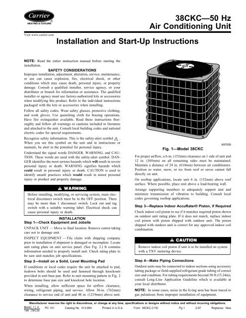
Fig. 1—Model 38CKC<br />
A97005<br />
For proper airflow, a 6-in. (152mm) clearance on 1 side of unit <strong>and</strong><br />
12 in. (305mm) on all remaining sides must be maintained.<br />
Maintain a distance of 24 in. (610mm) between air conditioners.<br />
Position so water, snow, or ice from roof or eaves cannot fall<br />
directly on unit.<br />
On rooftop applications, locate unit 6 in. (152mm) above roof<br />
surface. Where possible, place unit above a load-bearing wall.<br />
Arrange supporting members to adequately support unit <strong>and</strong><br />
minimize transmission of vibration to building. Consult local<br />
codes governing rooftop applications.<br />
Step 3—Replace Indoor AccuRater® Piston, if Required<br />
Check indoor coil piston to see if it matches required piston shown<br />
on outdoor unit rating plate. If it does not match, replace indoor<br />
coil piston with piston shipped with outdoor unit. The piston<br />
shipped with outdoor unit is correct for any approved indoor coil<br />
combination.<br />
Remove indoor coil piston if unit is to be installed on system<br />
with a TXV metering device.<br />
Step 4—Make Piping Connections<br />
Outdoor units may be connected to indoor sections using accessory<br />
tubing package or field-supplied refrigerant grade tubing of correct<br />
size <strong>and</strong> condition. For tubing requirements beyond 50 ft (15.24m),<br />
consult Long-Line Application Guideline which is available at<br />
your local distributor.<br />
NOTE: In some cases, noise in the living area has been traced to<br />
gas pulsations from improper installation of equipment.<br />
Manufacturer reserves the right to discontinue, or change at any time, specifications or designs without notice <strong>and</strong> without incurring obligations.<br />
Book 1 4 PC 101 Catalog No. 013-894 Printed in U.S.A. Form 38CKC-C1SI Pg 1 2-97 Replaces: New<br />
Tab 3a 2a
AIR IN<br />
AIR <br />
DISCHARGE<br />
AIR IN<br />
AIR <br />
DISCHARGE<br />
AIR IN<br />
NOTES:<br />
1. Allow 30 in. (762 mm) clearance to service end of unit, 48 in. (1219 mm) above<br />
unit, 6 in. (152 mm) on one side, 12 in. (305 mm) on remaining side, <strong>and</strong><br />
24 in. (610 mm) between units for proper airflow.<br />
2. Minimum outdoor operating ambient in cooling mode is 55° F (12.8° C),<br />
MAX. 125° F (51.7° C).<br />
3. Dimensions in parentheses are in millimeters.<br />
4. Series designation is the 13th position of the unit model number.<br />
AIR IN<br />
AIR DISCHARGE<br />
A<br />
G<br />
RATING PLATE<br />
FIELD POWER SUPPLY CONN<br />
7/8 IN. DIA (22.22) HOLE WITH <br />
1 1/8 IN. DIA (28.57) KNOCKOUT<br />
AND 1 3/8 IN. DIA (34.92) KNOCKOUT<br />
E<br />
B<br />
F DIA SUCTION LINE CONN<br />
FIELD CONTROL <br />
SUPPLY CONN<br />
7/8 IN. DIA (22.22) HOLE<br />
3/8<br />
IN. DIA (9.53) <br />
LIQUID LINE CONN<br />
UNIT SIZE<br />
A/B C D E F G<br />
In. mm In. mm In. mm In. mm In. mm In. mm<br />
018 18 457.2 3 76.2 15 381.0 10-3/16 258.8 5/8 15.9 25-15/16 658.8<br />
024 22-1/2 571.5 3-11/16 93.6 18-1/8 460.4 14-3/8 365.1 5/8 15.9 21-15/16 557.2<br />
036 22-1/2 571.5 3-11/16 93.6 18-1/8 460.4 14-3/8 365.1 3/4 19.1 33-15/16 862.0<br />
048 30 762.0 6-1/2 165.1 23-1/2 596.9 20 508.0 7/8 22.2 27-15/16 709.6<br />
060 30 762.0 6-1/2 165.1 23-1/2 596.9 20 508.0 7/8 22.2 39-15/16 1014.4<br />
Fig. 2—<strong>Unit</strong> Reference Drawing<br />
C<br />
D<br />
A97003<br />
INSTALLATION RECOMMENDATIONS<br />
1. Locate unit away from windows.<br />
2. Ensure that vapor <strong>and</strong> liquid tube diameters are appropriate to<br />
capacity of unit. (See Table 1.)<br />
3. Run refrigerant tubes as directly as possible by avoiding<br />
unnecessary turns <strong>and</strong> bends.<br />
4. Leave some slack between structure <strong>and</strong> unit to absorb<br />
vibration.<br />
5. When passing refrigerant tubes through the wall, seal opening<br />
with RTV or other pliable silicon-based caulk. (See Fig. 3.)<br />
6. Avoid direct lineset contact with water pipes, ductwork, floor<br />
joists, wall studs, floors, <strong>and</strong> walls.<br />
7. Do not suspend refrigerant tubing from joists <strong>and</strong> studs with a<br />
rigid wire or strap which comes in direct contact with tubing.<br />
(See Fig. 3.)<br />
8. Ensure that tubing insulation is pliable <strong>and</strong> completely surrounds<br />
vapor tube.<br />
9. When necessary, use hanger straps which are 1 in. (25mm)<br />
wide <strong>and</strong> conform to shape of tubing insulation. (See Fig. 3.)<br />
10. Isolate hanger straps from insulation by using metal sleeves<br />
bent to conform to shape of insulation.<br />
2<br />
If refrigerant tubes or indoor coil is exposed to atmosphere, it must<br />
be evacuated to 500 microns to eliminate contamination <strong>and</strong><br />
moisture in the system.<br />
To prevent compressor damage DO NOT bury more than 36<br />
in. (914mm) of refrigerant tubing. If ANY tubing is buried,<br />
provide 6 in. (152mm) vertical rise at service valve.<br />
OUTDOOR UNITS CONNECTED TO FACTORY-APPROVED<br />
INDOOR UNITS — Outdoor unit contains correct system refrigerant<br />
charge for operation with indoor unit of same size when<br />
connected by 15 ft (4.55m) of field-supplied or factory-accessory<br />
tubing. Check refrigerant charge for maximum efficiency.<br />
REFRIGERANT TUBING — Connect tubing to fittings on outdoor<br />
unit vapor <strong>and</strong> liquid service valves. (See Fig. 2.)<br />
Relieve pressure <strong>and</strong> recover all refrigerant before system<br />
repair or final unit disposal to avoid personal injury or death.<br />
Use all service ports <strong>and</strong> open all flow-control devices,<br />
including solenoid valves.
Table 1—Refrigerant Connections <strong>and</strong> Recommended Liquid <strong>and</strong> Vapor Tube Diameters<br />
LIQUID<br />
VAPOR<br />
UNIT SIZE<br />
Connection Dia Tube Dia Connection Dia Tube Dia<br />
In. mm In. mm In. mm In. mm<br />
018, 024 3/8 9.53 3/8 9.53 5/8 15.88 5/8 15.88<br />
036 3/8 9.53 3/8 9.53 3/4 19.05 3/4 19.05<br />
048 3/8 9.53 3/8 9.53 7/8 22.23 7/8 22.23<br />
060 3/8 9.53 3/8 9.53 7/8 22.23 1-1/8 28.58<br />
NOTES: 1. Tube diameters are for lengths up to 50 ft (15.24m). For tube sets over 50 ft (15.24m), consult Long-Line Application Guideline.<br />
2. Do not apply capillary tube indoor coils to these units.<br />
To prevent damage to unit or service valves observe the<br />
following:<br />
• Use a brazing shield.<br />
• Wrap service valves with wet cloth or use a heat sink<br />
material.<br />
SWEAT CONNECTION — Use refrigerant grade tubing. Service<br />
valves are closed from factory <strong>and</strong> ready for brazing. After<br />
wrapping service valve with a wet cloth, tubing set can be brazed<br />
to service valve using either silver bearing or non-silver bearing<br />
brazing material. Consult local code requirements. Refrigerant<br />
tubing <strong>and</strong> indoor coil are now ready for leak testing. This check<br />
should include all field <strong>and</strong> factory joints.<br />
NOTE: Operation of unit on improper line voltage constitutes<br />
abuse <strong>and</strong> could affect unit reliability. See unit rating plate. Do not<br />
install unit in system where voltage or phase imbalance may<br />
fluctuate above or below permissible limits.<br />
NOTE: Use copper wire only between disconnect switch <strong>and</strong><br />
unit.<br />
NOTE: Install branch circuit disconnect per local codes of<br />
adequate size to h<strong>and</strong>le unit starting current. Locate disconnect<br />
within sight from <strong>and</strong> readily accessible from unit per local codes.<br />
To avoid personal injury or death, do not supply power to unit<br />
with compressor terminal box cover removed.<br />
NOTE: Avoid contact between tubing <strong>and</strong> structure.<br />
OUTDOOR WALL INDOOR WALL<br />
CAULK<br />
LIQUID TUBE<br />
The unit cabinet must have an uninterrupted or unbroken<br />
ground to minimize personal injury if an electrical fault<br />
should occur. The ground may consist of electrical wire or<br />
metal conduit when installed in accordance with existing<br />
electrical codes. Failure to follow this warning can result in an<br />
electric shock, fire, or death.<br />
INSULATION<br />
HANGER STRAP<br />
(AROUND VAPOR<br />
TUBE ONLY)<br />
THROUGH THE WALL<br />
VAPOR TUBE<br />
JOIST<br />
INSULATION<br />
VAPOR TUBE<br />
ROUTE GROUND AND POWER WIRES — Remove access<br />
panel <strong>and</strong> control box cover to gain access to unit wiring. Extend<br />
wires from disconnect through power wiring hole provided <strong>and</strong><br />
into unit control box. (See Fig. 2.) Size wires per local codes, but<br />
not smaller than minimum wire size shown on unit rating plate.<br />
CONNECT GROUND AND POWER WIRES — Connect ground<br />
wire to ground connection in control box for safety. Connect<br />
power wiring to contactor as shown in Fig. 4.<br />
DISCONNECT<br />
PER N.E.C. AND/OR<br />
LOCAL CODES<br />
CONTACTOR<br />
1″ MIN<br />
(25 mm)<br />
SUSPENSION<br />
LIQUID TUBE<br />
FIELD POWER<br />
WIRING<br />
3 PHASE ONLY<br />
BLUE<br />
Fig. 3—Piping <strong>Installation</strong><br />
Step 5—Make Electrical Connections<br />
A94330<br />
FIELD GROUND<br />
WIRING<br />
GROUND<br />
LUG<br />
Fig. 4—Line Power Connections<br />
A94025<br />
Be sure field wiring complies with local <strong>and</strong> national fire, safety,<br />
<strong>and</strong> electrical codes, <strong>and</strong> voltage to system is within limits shown<br />
on unit rating plate. Contact local power company for correction of<br />
improper voltage. See unit rating plate for recommended circuit<br />
protection device.<br />
NOTE: Use No. 18 AWG (American Wire Gage) color-coded,<br />
insulated (35° C minimum) wire. If thermostat is located more than<br />
100 ft (30.5m) from unit as measured along control voltage wires,<br />
use No. 16 AWG color-coded wires to avoid excessive voltage<br />
drop.<br />
3
CONNECT CONTROL WIRING — Route 24-v control wires<br />
through control wiring grommet <strong>and</strong> connect to brown <strong>and</strong> blue<br />
pigtails supplied in unit splice box. (See Fig. 5.)<br />
Use furnace transformer, fan-coil transformer, or accessory transformer<br />
for control power, 24-v/40-va minimum.<br />
NOTE: Use of available 24-v accessories may exceed minimum<br />
40-va power requirement. Determine total transformer loading <strong>and</strong><br />
increase transformer capacity or split load with an accessory<br />
transformer as required.<br />
Step 6—Compressor Crankcase Heat<br />
When equipped with a crankcase heater, energize heater a minimum<br />
of 24 hr before starting unit. To energize heater only, set<br />
thermostat to OFF <strong>and</strong> close electrical disconnect to outdoor unit.<br />
A crankcase heater is required if the refrigerant tubing is longer<br />
than 50 ft (15.24m).<br />
Step 7—Install Electrical Accessories, If Any<br />
Refer to individual instructions packaged with kit or accessory<br />
when installing.<br />
Step 8—<strong>Start</strong>-Up <strong>and</strong> Check Charge<br />
To prevent compressor damage or personal injury, observe<br />
the following:<br />
• Do not overcharge system with refrigerant.<br />
• Do not operate unit in a vacuum or at negative pressure.<br />
• Do not disable low-pressure switch.<br />
In scroll compressor applications:<br />
• Dome temperatures may be hot.<br />
• In 3-phase application, incorrect phasing will cause reverse<br />
rotation, resulting in elevated noise levels, equalized pressures,<br />
<strong>and</strong> reduced current draw. Correct by reversing power<br />
connection L1 <strong>and</strong> L2 on contactor.<br />
Do not vent refrigerant to atmosphere. Recover during system<br />
repair or final unit disposal.<br />
1. Fully back seat (open) liquid <strong>and</strong> vapor tube service valves.<br />
2. <strong>Unit</strong> is shipped with valve stem(s) front seated <strong>and</strong> caps<br />
installed. Replace stem caps after system is opened to refrigerant<br />
flow (back seated). Replace caps finger-tight <strong>and</strong> tighten<br />
additional 1/6 turn with wrench.<br />
3. Close electrical disconnects to energize system.<br />
4. Set room thermostat to desired temperature. Be sure set point<br />
is below indoor ambient temperature.<br />
5. Set room thermostat to COOL <strong>and</strong> fan to FAN or AUTO<br />
mode, as desired. Operate unit for 15 minutes. Check system<br />
refrigerant charge.<br />
6. Factory charge is shown on outdoor unit rating plate. Adjust<br />
charge by following procedure shown on charging tables<br />
located on outdoor unit.<br />
Step 9—Service <strong>and</strong> Maintenance<br />
For continued high performance, <strong>and</strong> to minimize possible equipment<br />
failure, periodic maintenance MUST be performed on this<br />
equipment.<br />
Leave User’s Manual with owner. Explain system operation <strong>and</strong><br />
periodic maintenance requirements outlined in manual. Frequency<br />
of maintenance may vary depending on geographic areas, such as<br />
coastal applications which require more frequent maintenance.<br />
To prevent personal injury wear safety glasses, protective<br />
clothing, <strong>and</strong> gloves when h<strong>and</strong>ling refrigerant <strong>and</strong> observe<br />
the following:<br />
• Back seating service valves are not equipped with Schrader<br />
valves. Fully back seat (counter clockwise) valve stem before<br />
removing gage port cap.<br />
• Front seating service valves are equipped with Schrader<br />
valves.<br />
4
THERMOSTAT THERMOSTAT FURNACE<br />
R<br />
G<br />
Y<br />
IFR<br />
C<br />
MOTOR<br />
POWER<br />
M SUPPLY<br />
TRANS<br />
R<br />
G<br />
Y<br />
R<br />
C<br />
G<br />
Y<br />
C<br />
W<br />
W /W1<br />
COOLING ONLY<br />
ONE STAGE COOLING / GAS HEATING<br />
THERMOSTAT FAN COIL THERMOSTAT INDOOR UNIT<br />
R<br />
R<br />
R<br />
R<br />
C<br />
C<br />
G<br />
G<br />
C<br />
G<br />
G<br />
LLS<br />
C<br />
Y<br />
Y<br />
Y<br />
Y<br />
W<br />
W2<br />
W<br />
W<br />
ONE STAGE COOLING / ELECTRIC HEAT<br />
ONE STAGE COOLING / HEATING<br />
ACCESSORY LIQUID LINE SOLENOID<br />
NOTES:<br />
1. Wiring must conform to local codes.<br />
2. LLS required on some units. See specific unit instructions.<br />
3. Transformer required is 24-v, 40-va minimum. A 60-va or external power source may<br />
be necessary when installing accessories.<br />
4. When installing electronic thermostat, connect transformer common to thermostat C.<br />
LEGEND:<br />
C<br />
– COMPRESSOR CONTACTOR<br />
M<br />
– INDOOR FAN MOTOR<br />
LLS<br />
– LIQUID LINE SOLENOID<br />
TRANS<br />
– TRANSFORMER<br />
IFR<br />
– INDOOR FAN RELAY<br />
Fig. 5—24-v Control Circuit Connections<br />
A94331<br />
5
Copyright 1997 CARRIER Corp. • 7310 W. Morris St. • Indianapolis, IN 46231<br />
38ckcc1s<br />
Manufacturer reserves the right to discontinue, or change at any time, specifications or designs without notice <strong>and</strong> without incurring obligations.<br />
Book 1 4 PC 101 Catalog No. 013-894 Printed in U.S.A. Form 38CKC-C1SI Pg 8 2-97 Replaces: New<br />
Tab 3a 2a


