SERVICE BULLETIN No.1147 - ABC Companies
SERVICE BULLETIN No.1147 - ABC Companies
SERVICE BULLETIN No.1147 - ABC Companies

Create successful ePaper yourself
Turn your PDF publications into a flip-book with our unique Google optimized e-Paper software.
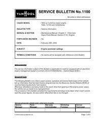
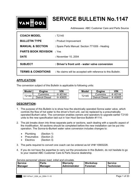
<strong>SERVICE</strong> <strong>BULLETIN</strong> <strong>No.1147</strong><br />
Addressees: <strong>ABC</strong> Customer Care and Parts Source<br />
COACH MODEL<br />
<strong>BULLETIN</strong> TYPE<br />
MANUAL & SECTION<br />
PARTS BOOK REVISION<br />
: T2145<br />
: Product Improvement<br />
: Spare Parts Manual: Section 771009 - Heating<br />
: Yes<br />
DATE : November 10, 2004<br />
SUBJECT<br />
TERMS & CONDITIONS<br />
: Driver’s front unit - water valve conversion<br />
: No claims will be accepted with reference to this Bulletin.<br />
APPLICATION:<br />
The conversion subject of this Bulletin is applicable to following units:<br />
Model Engine VIN Model Engine VIN<br />
Cummins ! 40144 Cummins ! 40144<br />
T2140<br />
T2145<br />
Detroit Diesel ! 40605<br />
Detroit Diesel ! 40605<br />
DESCRIPTION:<br />
1. The purpose of this Bulletin is to show how the electrically operated Sonna water valve, which<br />
controls the flow of hot water to the driver’s front unit, can be replaced by a pneumatically<br />
operated Burkert valve. The conversion enables owners and operators to upgrade earlier T2100<br />
units to the new specification laid out in Van Hool Service Bulletin #1114.<br />
2. The job breaks down into three separate parts or sections, each dealing with a specific aspect of<br />
the modification. All sections should be completed before the new installation can be put into<br />
operation. The Sonna-to-Burkert water valve conversion includes changes to:<br />
• Plumbing (Section 1)<br />
• Pneumatics (Section 2)<br />
• Electrics (Section 3)<br />
3. The parts required to convert one coach can be ordered as kit VH# 10900228.<br />
4. If you do not have the expertise to carry out the procedures in this Bulletin, do not hesitate to go<br />
to your nearest <strong>ABC</strong> Customer Care & Parts Source dealership.<br />
Service personnel: please read, initial and circulate.<br />
Service<br />
Manager<br />
Parts<br />
Manager<br />
Warranty<br />
Administrator<br />
Workshop<br />
Foreman<br />
Service<br />
Technician<br />
SB1147rev1_USA_en_2004-11-10<br />
Page 1 of 20
PARTS AND PRODUCTS:<br />
Order one kit VH 10900228 for one T2100 unit to modify. The kit contains following parts:<br />
Plumbing (refer also to Section 1)<br />
Position Part No. Description Qty.<br />
7 VH 10835796 Tube assembly, single elbow 1<br />
8 VH 660203101 Nut M6 5<br />
9 VH 660636300 Lock washer M6 5<br />
10 VH 660623501 Plain washer M6 5<br />
11 VH 611217490 Support bracket 2<br />
12 VH 660220304 Bolt, M6x20 5<br />
13 VH 637100170 Clamp 1<br />
14 VH 635102530 Connector 2<br />
15 VH 10830469 Pneumatically operated water valve, Burkert 1<br />
16 VH 625100490 Hose, transition, 28 to 34 mm 1<br />
N/S VH 10716348 Hose clamp for VH 625100490 1<br />
17 VH 10835795 Tube assembly, double elbow 1<br />
20 VH 10835797 Tube assembly, U 1<br />
21 VH10 716348 Hose clamp 2<br />
22 VH 625101030 Throttle insert, 28 mm ∅ hose 1<br />
23 VH 621401460 Hose, elbow, 28 mm ∅ 1<br />
24 VH 10835798 Tube assembly, T branch 1<br />
N/S VH 660613601 Rivet nut, 6 mm 1<br />
N/S Local purchase Loctite #577, pipe sealant #<br />
Pneumatics (refer also to Section 2)<br />
Position Part No. Description Qty.<br />
1 VH 637211940 Solenoid valve 1<br />
2 VH 637317600 Fitting, elbow, adjustable w/ throttle insert 1<br />
3 VH 637307010 Insert, tube 2<br />
4 VH 637307060 Cutting ring 2<br />
5.1 VH 637302850 Nut, 6 mm ∅ for VH 637317600 1<br />
5.2 VH 637314350 Nut, 6 mm ∅ for VH 637306490 1<br />
6 VH 660515907 Tube, plastic, black, 6 mm ∅ #<br />
18 VH 637306490 Fitting, elbow ¼ inch - 6 mm 1<br />
19 VH 10516489 Muffler 1<br />
N/S Local purchase Mounting clips, self adhesive 4<br />
Electrics (refer also to Section 3)<br />
Part No. Description Qty.<br />
VH 10689684 Temperature control switch, UWE Easy Term 2000 1<br />
VH 10737771 Connector, 7-pin for VH 10689684 1<br />
VH 10832235 Air temperature sensor 1<br />
Local purchase Automotive electrical wire, 16 AWG, brown #<br />
Local purchase Automotive electrical wire, 16 AWG, red-yellow #<br />
Local purchase Automotive electrical wire, 12 AWG, blue #<br />
• Parts may be purchased from your nearest <strong>ABC</strong> <strong>Companies</strong> Parts Source dealership.<br />
• Parts and products disposition : discard according to applicable environmental regulations.<br />
Page 2 of 20 SB1147rev1_USA_en_2004-11-10
Sonna to Burkert water valve conversion<br />
Plumbing and pneumatics – new parts required (numbered items only)<br />
1<br />
8 9 10 11<br />
2<br />
3 4 5 .1<br />
7<br />
6<br />
13<br />
12<br />
14<br />
14<br />
16<br />
15<br />
20<br />
5.25<br />
3 4<br />
18<br />
19<br />
17<br />
21<br />
21<br />
22<br />
24<br />
23<br />
Figure 1: Exploded view -<br />
Plumbing and pneumatic parts<br />
and hardware required for the<br />
Sonna to Burkert water valve<br />
conversion<br />
SB1147rev1_USA_en_2004-11-10<br />
Page 3 of 20
SECTION 1: SONNA-TO-BURKERT WATER VALVE CONVERSION - PLUMBING<br />
Plumbing - parts required:<br />
Refer to Figures 1 and 2, and to the parts list on page 2 of this Bulletin.<br />
VH 10835797<br />
VH 625100490<br />
VH 10835796<br />
VH 10835795<br />
VH 10577844<br />
PROCEDURE:<br />
VH 10835798<br />
VH 621401460<br />
Figure 2: Burkert<br />
replacement valve<br />
VH 10577844.<br />
On coach<br />
installation of major<br />
components<br />
1. General:<br />
• This section explains how to:<br />
! isolate the electrically operated water valve from the heating system<br />
! remove the valve, its associated hardware and electronics from the valve panel<br />
! install the pneumatically operated valve and tubing<br />
• For your information only: the labor estimate for this conversion is approximately 4 hours.<br />
• This job should be executed by a technician experienced in HVAC maintenance.<br />
• For more information refer to the coach Maintenance Manual, the Operator’s Guide Book,<br />
and the Spare Parts Manual.<br />
2. Special tools, equipment or services:<br />
• No special tools, equipment or services are required.<br />
3. Preparations:<br />
• Park the coach on a level-surfaced service pit with the front wheels straight.<br />
Apply the parking brake and shut down the engine.<br />
• Switch off all systems with the exception of the HVAC system.<br />
Leave the battery master switch on.<br />
• Put a “DO NOT OPERATE” tag on the instrument panel.<br />
Procedure continued on page 6 of 20<br />
Page 4 of 20 SB1147rev1_USA_en_2004-11-10
F03517<br />
Figure 3: Location of gate valves in the T2145<br />
combustion heater compartment (valves in the<br />
closed position)<br />
Supply to parcel shelf<br />
Return from parcel shelf<br />
Main return to<br />
engine<br />
Return from front heater<br />
Supply to front heater<br />
Main supply from<br />
engine<br />
Supply RH<br />
plinths<br />
Return RH plinths<br />
3<br />
Bypass<br />
ELECTRICAL<br />
SONNA 3-WAY<br />
CONTROL<br />
VALVE FOR<br />
FRONT UNIT<br />
(KE3A)<br />
VH 10613590<br />
TO BE<br />
REPLACED BY<br />
PNEUMATIC<br />
BURKERT<br />
VALVE<br />
VH 10577844<br />
2<br />
1<br />
Supply LH plinths<br />
Return LH plinths<br />
Figure 4: T2100 heating valve installation – eartly specification with electrically operated valve for<br />
front unit. The engine main supply and return valves are in the open position.<br />
SB1147rev1_USA_en_2004-11-10<br />
Page 5 of 20
Preparations continued from page 4:<br />
• Install wheel chocks.<br />
• Allow coolant to cool down to approximately 95°F (35°C).<br />
• Read the entire procedure before beginning to work.<br />
CAUTION: Observe safe shop practices at all times.<br />
4. To drain the heating system for water valve replacement:<br />
1) Turn the driver’s temperature selector knob counterclockwise to the zero position.<br />
2) Switch-off and disconnect the combustion heater.<br />
3) Close the combustion heater gate valves.<br />
! T2140: The gate valve in the heating supply line is located behind the right-hand engine<br />
compartment door. The gate valve in the heating return line is accessible via the interior<br />
access trap above the transmission.<br />
! T2145: Both valves are located in the combustion heater compartment on the left-hand<br />
side of the coach (see Figure 3).<br />
4) At the back of the luggage compartment, open the access door to the heating system valve<br />
and pump panel. Close the ball valves in the engine main supply (2, Figure 4) and return<br />
lines (3, Figure 4). In the closed position, the valve levers should be at 90° to the tubing.<br />
5) Working underneath the coach, in front of the drive axle, attach a suitable hose to the drain<br />
pipe of the drip pan below the heating system valve and pump panel.<br />
Install a suitable clean container to catch approximately 3 gallons of coolant.<br />
6) Undo the lower hose clamp of the engine main supply hose beneath the water valve (refer<br />
to 1, Figure 4). Carefully remove the hose from its fitting and allow coolant to drain.<br />
5. To remove the electrically operated water valve and ancillaries (see Figure 5):<br />
1) Undo and remove the bolts, nuts and washers securing the T-branch tube assembly (return<br />
from front heater) to its mounting bracket (1, Figure 5). Withdraw the clamp<br />
2) Unscrew the large nut securing the T-branch tube assembly to the ball valve (2, Figure 5).<br />
3) Unscrew and back-up the clamp securing the lower by-pass hose to the T-branch tube<br />
assembly (3, Figure 5)<br />
4) Unscrew and back-up the clamp securing the front heater supply hose to the elbow tube<br />
assembly, which connects to the valve (4, Figure 5).<br />
5) Unscrew and back-up the clamp securing the front heater return hose to the T-branch tube<br />
assembly (5, Figure 5).<br />
6) Unscrew and back-up the clamp securing the main supply from engine hose to the U-tube<br />
assembly (6, Figure 5).<br />
7) Undo and remove the two bolts securing the water valve mounting bracket to the valve<br />
panel (7, Figure 5).<br />
Page 6 of 20 SB1147rev1_USA_en_2004-11-10
7<br />
8<br />
4<br />
5<br />
6<br />
3<br />
1<br />
2<br />
Figure 5: T2100 heating valve installation – early specification with electrically operated valve<br />
for front unit. Valve removal squence.<br />
8) Cut the tie wrap securing the water valve-to-control box multiwire connector.<br />
Separate the connector terminals (8, Figure 5).<br />
9) Pry-loose the hose ends of which the clamps have been undone and withdraw the valve<br />
assembly from the water valve and pump compartment.<br />
10) Undo and remove the screws securing the valve control box to the valve and pump<br />
compartment wall (see Figure 6). Tie the control box out of the way. It will be removed later<br />
in the procedure (see Section 3: Sonna-to-Burkert water valve conversion – Electrics).<br />
F04935<br />
Figure 6: Location of water valve<br />
electronic control box<br />
SB1147rev1_USA_en_2004-11-10<br />
Page 7 of 20
11) Proceed with Section 2: Sonna to Burkert water valve conversion – Pneumatics.<br />
12) Proceed with Section 3: Sonna to Burkert water valve conversion – Electrics;<br />
6. To install the pneumatically operated water valve and tubing<br />
VH 10835797<br />
VH 625100490<br />
VH 10835795<br />
VH 10835795<br />
VH 621104460<br />
VH 10577844<br />
VH 10835798<br />
Figure 7: Plumbing main replacement parts<br />
1) If not already fitted, install the fittings (14, Figure 1) into the water valve body. Use Loctite<br />
adhesive #577 on the threads and secure hand tight.<br />
2) Assemble the valve (position 15), the single elbow (position 7), double elbow (position17)<br />
and U-tube (position 20) as shown in Figure 1 for a loose fit. Use Loctite adhesive #577 on<br />
the threaded part of the double elbow tube assembly (4, Figure 5).<br />
Note that the valve is installed with the actuating cylinder pointing down.<br />
3) If not already fitted, install the throttle insert halfway (22, Figure 1) into the elbow hose (23,<br />
Figure 1). On the outside of the tube, mark the location of the insert with green tape.<br />
4) Using recovered hose clamps, attach the elbow hose (23, Figure 1) to the U-tube (20,<br />
Figure 1) and the T-branch tube assembly (24, Figure 1).<br />
5) Hook-up the new valve and tube assembly to the coach heating system as shown in<br />
Figures 2 and 7. Refer to Figure 8 if a mismatch exists between the main supply (Figure 4)<br />
tube diameter and the double elbow tube assembly (17, Figure 2).<br />
6) Attach the lower by-pass hose to the new T-branch tube assembly.<br />
7) To connect the new T-branch tube assembly to the ball valve (see 2, Figure 5), run up the<br />
large nut to finger tight.<br />
Page 8 of 20 SB1147rev1_USA_en_2004-11-10
1 2<br />
VH 625100490<br />
5<br />
3<br />
4<br />
Figure 8: Burkert pneumatic water valve plumbing – installation recommendations<br />
1. Early T2100s have a 28 mm (1-7/64 inch) OD tube<br />
2. Later T2100s have 34 mm (1-11/32 inch) OD tubing.<br />
3. The double elbow tube assembly is 34 mm OD only.<br />
To connect 28 mm OD tubing to the 34 mm OD double elbow tube assembly, fit 28 to 34 mm<br />
transition hose VH 625100490.<br />
4. The threaded part of tube assembly VH 10835795 screws into the Burkert valve.<br />
5. Use Loctite 577 pipe sealant on threaded parts of valve.<br />
8) Install the valve mounting bracket (11, Figure 1) and clamp (13, Figure 1) for a loose fit<br />
using the associated fasteners.<br />
9) On the valve panel, mark the point where the mounting bracket (11, Figure 1) should be<br />
attached to it. Remove the bracket and clamp assembly.<br />
10) In the valve panel, using the mark from step nine as a reference, drill a suitable hole to<br />
accept a 6 mm rivet nut. Install the rivet nut.<br />
11) Reinstall the bracket and clamp assembly. Secure the bracket to the valve mounting plate<br />
with a 6 mm bolt and the rivet nut installed in step 10. Tighten all bolts to 80 in.lbf (9 Nm).<br />
12) Make sure all hoses fit the tubing properly. Secure the constant torque hose clamps as<br />
shown in the chart below.<br />
Type Width Washers Torque Tip extension @ torque<br />
Constant torque A 9/16 inch 4 40 ! 70 in.lbf 7/32 inch<br />
Constant torque B 5/8 inch 5 90 ! 125 in.lbf ¼ inch<br />
SB1147rev1_USA_en_2004-11-10<br />
Page 9 of 20
13) Check the large nuts of the T-branch, double elbow and U-tube assemblies for tightness<br />
(tubing seated + finger tight + ½ turn).<br />
7. To add coolant to the engine cooling and heating system:<br />
1) With the lower hose of the engine main supply line refitted, and the hose clamp properly<br />
torqued, open the ball valves in the engine main supply (2, Figure 4) and return lines (3,<br />
Figure 4). Open the gate valves (see Figure 3).<br />
2) Refill the cooling system, referring to Chapter 2 of the Maintenance Manuals. Drained<br />
coolant may be recovered if it is not contaminated and meets the specifications in the<br />
Maintenance Manual.<br />
3) While running the engine for about 20 minutes, check cooling system plumbing for leaks.<br />
Rectify if necessary.<br />
4) Reconnect the combustion heater.<br />
5) Check “all systems go” on the multifunction display (indicated by an asterisk on the bottom<br />
middle of the display).<br />
6) Shut down the engine. Remove the wheel chocks and the warning label on the instrument<br />
panel.<br />
7) Remove the drain pan and hose underneath the coach.<br />
Procedure “Section 1 – Plumbing” complete.<br />
Page 10 of 20 SB1147rev1_USA_en_2004-11-10
SECTION 2: SONNA-TO-BURKERT WATER VALVE CONVERSION - PNEUMATICS<br />
Pneumatics – parts required:<br />
Refer to Figure 1, and to the parts list on page 2 of this Bulletin.<br />
PROCEDURE:<br />
1. General:<br />
• This job should be executed by a technician experienced in air system service.<br />
• For more information refer to the Pneumatics Diagram Booklet that comes with the coach.<br />
2. Special tools, equipment or services:<br />
• No special tools, equipment or services are required.<br />
3. Preparations:<br />
• Make sure all systems have been switched off and that the battery master switch is off.<br />
• Vent the auxiliary air tank.<br />
• Read the entire procedure before beginning to work.<br />
4. To install supplementary solenoid valve V115:<br />
CAUTION: Observe safe shop practices at all times.<br />
CAUTION: Never connect or disconnect a hose, tube or line containing air pressure. It<br />
may whip as air escapes. Never remove a component or open a line unless you are<br />
certain that all system air pressure has been vented.<br />
CAUTION: Never exceed the recommended air pressure and always wear safety glasses<br />
when working on air systems.<br />
• To operate the Burkert water valve, a supplementary solenoid valve should be installed next<br />
to the existing solenoid valve bank on the heating system valve and pump panel in the<br />
luggage compartment (see Figure 9). Proceed as follows:<br />
Figure 9: Location of solenoid valve<br />
V115 on new production coaches.<br />
1) With the Sonna water valve and associated tubing removed from the coach, cut loose the<br />
tie wraps securing the solenoid valves’ wiring harness.<br />
SB1147rev1_USA_en_2004-11-10<br />
Page 11 of 20
2) With a 4 mm Allen wrench, undo and remove the two Allen bolts securing the solenoid valve<br />
bank to the water valve mounting plate (see Figure 10). Take care not to drop the nylon<br />
back-up washers separating the valve bank from the mounting plate.<br />
F04465<br />
Figure 10: Location of solenoid valve<br />
bank retaining bolts<br />
3) Withdraw the solenoid valve bank and separate solenoid valve #V127 from the rest by<br />
undoing the angled Allen screw between valve #V127 and valve #V126.1. Use a 3 mm<br />
Allen wrench. Make sure not to drop the #1 port O-ring.<br />
4) Fit male stud elbow VH 637317600 to the #2 port of the supplementary solenoid valve.<br />
Point the connector in the 4 o’ clock position and secure in this position with the jam nut with<br />
recessed O-ring. Make sure the transit port to the next valve is open. Open-up if necessary.<br />
5) Apply some Vaseline to the O-ring counterbore of the #1 port of the supplementary valve<br />
and fit the O-ring.<br />
6) Attach the supplementary valve to the rest of the valve bank using the 4 mm Allen screw<br />
included with the valve. Secure hand tight.<br />
7) Repeat steps 5 and 6 for solenoid valve #V127.<br />
8) Reinstall the complete valve bank making sure to refit the nylon spacers between the valve<br />
bank van the water valve mounting plate. Secure the Allen bolts hand tight. Switch the<br />
yellow valve lever to the “0” position (see Figure 11).<br />
Figure 11: Solenoid valve with yellow<br />
lever in the “0” position<br />
9) Using an insert, a nut and a cutting ring, attach approximately 11/2 ft of 6 mm tubing to the<br />
elbow fitting installed in the #2 port of the supplementary solenoid valve. Refer to the plastic<br />
tubing installation techniques below.<br />
Page 12 of 20 SB1147rev1_USA_en_2004-11-10
Plastic tubing installation techniques<br />
1) Cut off tubing to length squarely with a tube cutter.<br />
Any burrs, either on the outside or inside must be removed.<br />
2) Slide the nut, followed by the sleeve, on the tubing.<br />
Place the special insert in the end so the sleeve will not crush the tube.<br />
When the tube is aligned with the fitting, insert the tubing, until it bottoms on the<br />
seat.<br />
3) While holding the tubing in, run up the nut finger-tight.<br />
Using a tubing wrench, bring the nut up until the sleeve just grabs the tubing.<br />
4) To tighten, give the nut the additional turns indicated in the table below, while<br />
holding the tubing in the fitting.<br />
NOTE:<br />
• Always use the right-size wrench. It must fit the hex securely. A loose fitting<br />
wrench will round off the corners and slip.<br />
• When tightening fittings, always support one portion with one wrench, while<br />
tightening with another.<br />
Tube O.D.<br />
Fractional inch<br />
1/ 4<br />
3/8 and 1/2<br />
5/8 and ¾<br />
T.F.F.T. *<br />
3<br />
4<br />
3.5<br />
* Additional number of turns from finger-tight<br />
NOTE: The foregoing tightening procedure applies to new compression fittings<br />
only. When assembling used (preset) fittings, bring up the nut firmly without<br />
additional turns.<br />
10) Route the plastic tubing to the pneumatic water valve location.<br />
Attach the tubing to the water valve mounting plate with self-adhesive mounting clips.<br />
11) Install the water valve and tube assembly referring to section 1 of this work procedure.<br />
12) Install elbow fitting VH 637306490 and muffler VH 10525687 in the water valve actuating<br />
cylinder as shown in Figure 12.<br />
Make sure to apply a drop of Loctite 577 pipe sealant to the tapered studs. The elbow<br />
should point approximately 45° from the vertical.<br />
13) Cut the plastic tubing to length. Using an insert, a nut and a cutting ring, attach the tubing to<br />
the elbow fitting installed in step 12.<br />
SB1147rev1_USA_en_2004-11-10<br />
Page 13 of 20
14) Attach the plastic tubing to the elbow fitting of the water valve actuating cylinder as shown in<br />
Figure 12.<br />
Figure 12: Solenoid valve actuating<br />
cylinder – elbow fitting and muffler<br />
installation<br />
Procedure “Section 2 – Pneumatics” complete.<br />
Page 14 of 20 SB1147rev1_USA_en_2004-11-10
SECTION 3: SONNA - TO- BURKERT WATER VALVE CONVERSION - ELECTRICS<br />
Electrics - parts required:<br />
Refer to Figures 13 and 14, and to the parts list on page 2 of this Bulletin.<br />
Figure 13: UWE Easy Term 2000 defroster<br />
control switch VH 10689684 and 7 pin,<br />
secondary lock connector. Arrows indicate<br />
the screws which secure the connector to the<br />
housing.<br />
PROCEDURE:<br />
CAUTION: Observe safe shop practices at all times.<br />
1. General:<br />
• This job should be executed by an experienced automotive electrician.<br />
• The wiring diagram with the new heating water valve control has been included in this<br />
Service Bulletin (see “Attachment 1: T2100 - New spec wiring diagram for front heating with<br />
pneumatic water valve” at the end of this section).<br />
• For more information refer to the Electrical Wiring Diagram Booklet that comes with the<br />
coach.<br />
2. Special tools, equipment or services:<br />
• No special tools, equipment or services are required.<br />
3. Preparations:<br />
• Make sure all systems have been switched off and that the battery master switch is off.<br />
• Read the entire procedure before beginning to work.<br />
SB1147rev1_USA_en_2004-11-10<br />
Figure 14: VH 10832235 Front unit air<br />
temperature sensor fits in windscreen<br />
ventilation duct<br />
Page 15 of 20
4. To change the water valve wiring – dashboard:<br />
1) Undo and remove the screws securing the dashboard switch panel, which is located to the<br />
right of the steering wheel. Withdraw the panel to gain access to the defroster air duct, which<br />
runs directly behind the panel (see Figure 15).<br />
Figure 15: Defroster air duct and<br />
temperature sensor VH 10832235<br />
2) Drill an 8 mm diameter hole in the duct, approximately in the location indicated in Figure 15.<br />
Install the sensor and grommet in the hole. Route the attached sensor wires towards the<br />
lower HVAC control panels below (see Figure 16). Secure the sensor wires with tie wraps.<br />
KL117<br />
1 2 3 4 5<br />
R120<br />
new<br />
R120 old<br />
S115<br />
9 8<br />
7<br />
6<br />
Figure 16: Early HVAC control panel with digital passenger compartment temperature control,<br />
auxiliary heater controls and temperature controls for the driver’s compartment. 1. Passenger<br />
compartment temperature control. 2. HVAC system auto ON. 3. Fresh air control switch. 4.<br />
Auxiliary heater switch. 5. Auxiliary heater tell -tale lamp (KL117). 6. Driver’s fresh/recirculated air<br />
control switch. 7. Defroster switch (S115). 8. Blank. 9. Temp control driver’s compartment (R120).<br />
3) Reinstall the dashboard switch panel.<br />
4) To gain access to the rear of the HVAC controls, undo and remove the control panel<br />
mounting screws. Withdraw the panels.<br />
5) Unplug the Sonna temperature control switch (see Figure 17).<br />
Remove the control knob, unscrew the nut securing the switch to the panel, remove the dial<br />
Page 16 of 20 SB1147rev1_USA_en_2004-11-10
plate and withdraw the switch and attached wiring (see Figure 17).<br />
Mark the control switch counter plug (connector) for future reference.<br />
LABEL COUNTER PLUG<br />
BEFORE REMOVAL<br />
Figure 17: Sonna temperature control switch<br />
6) Remove the switch blanking plate (8, Figure 16).<br />
In this location, install UWE Easy Term temperature control switch VH 10689684.<br />
7) Behind the HVAC control panels, locate the connector marked in step 5.<br />
Separate the connector from its wiring.<br />
From the connector wiring loom, cut-off the blue, and yellow-green wires.<br />
Using a butt connector, attach a piece of red-yellow wire to the brown wire of the wiring<br />
loom. Connect the red-yellow wire to terminal #3 of the new temperature control switch (see<br />
Figure 20).<br />
8) Connect the temperature sensor wires to terminals #5 and #6 of the new temperature control<br />
switch (see Figure 20).<br />
9) Install a length of brown wire between terminal #1 of the new temperature control switch and<br />
the ground wire of auxiliary heater tell-tale lamp KL117 (5, Figure 16).<br />
10) Install a length of blue 12 AWG wire between terminal #2 of the new temperature control<br />
switch and terminal #3 of defroster switch S115 (7, Figure 16 and Figure 20).<br />
11) Check that the secondary lock connector of the new switch is secured properly to the switch<br />
housing.<br />
12) Reinstall the HVAC control panels.<br />
5. To change the water valve wiring – main junction box:<br />
1) In the luggage compartment, open the main junction box and locate connector P900 at the<br />
bottom of the left hand connector rack (see Figures 18 and 20). Cut-off the 12 AWG blue<br />
wire from terminal #2 of the plug. Tape the wire.<br />
SB1147rev1_USA_en_2004-11-10<br />
Page 17 of 20
Figure 18: Location of connector<br />
#P900<br />
2) Close the main junction box.<br />
6. To change the water valve wiring – water valve and pump panel:<br />
1) In the water valve and pump compartment, disconnect the electric water valve control box,<br />
which has been removed in step 10 of “Section 1 – Sonna to Burkert water valve conversion<br />
– plumbing”<br />
2) At the control box wiring loom (3 wires) cut-off the blue, and yellow-green wires (Figure 20).<br />
Extend the brown wire and route it and connect it to terminal #1 (Figure 19) of the newly<br />
installed solenoid valve connector (Figures 19 and 20)<br />
Connect a suitable ground wire to terminal 2, Figure 18 of the solenoid valve connector.<br />
3) Install the connector onto the solenoid valve and secure with the mounting screw.<br />
1<br />
2<br />
Figure 19: Solenoid valve hook-up<br />
1. Live wire<br />
2. Ground<br />
Procedure “Section 3 – Electrics” complete.<br />
DISCLAIMER:<br />
The procedures contained herein are not exclusive. Van Hool cannot possibly know, evaluate, or<br />
advise the transportation industry of all conceivable ways in which a procedure may be undertaken<br />
or of the possible consequences of each such procedure. Other procedures may be as good, or<br />
better, depending upon the particular circumstances involved.<br />
Each carrier who uses the procedures herein must first satisfy itself thoroughly that neither the<br />
safety of its employees or agents, nor the safety or usefulness of any products, will be jeopardized<br />
by any procedure selected.<br />
Page 18 of 20 SB1147rev1_USA_en_2004-11-10
Figure 20: T2100 Sonna to Burkert water valve conversion – electrics modification in practice.<br />
R120: water valve control switch. KL117: auxiliary heater tell-tale lamp. S115: defroster switch.<br />
P111: connector #111. P900: connector #900. V115: water valve solenoid<br />
SB1147rev1_USA_en_2004-11-10<br />
Page 19 of 20
UWE Easy<br />
Term defroster<br />
control switch,<br />
front unit<br />
temperature<br />
sensor, and<br />
water valve<br />
solenoid<br />
Attachment 1: T2100 - New spec wiring diagram for front heating with pneumatic water valve<br />
Page 20 of 20 SB1147rev1_USA_en_2004-11-10