Medianet Reference Guide - Cisco
Medianet Reference Guide - Cisco
Medianet Reference Guide - Cisco

Create successful ePaper yourself
Turn your PDF publications into a flip-book with our unique Google optimized e-Paper software.
<strong>Medianet</strong> <strong>Reference</strong> <strong>Guide</strong><br />
Last Updated: October 26, 2010
ii <strong>Medianet</strong> <strong>Reference</strong> <strong>Guide</strong> OL-22201-01
About the Authors<br />
Solution Authors<br />
John Johnston, Technical Marketing Engineer, CMO Enterprise Solutions Engineering<br />
(ESE), <strong>Cisco</strong> Systems<br />
John Johnston<br />
John has been with <strong>Cisco</strong> for 10 years, with previous experience as a network consulting engineer in <strong>Cisco</strong>'s<br />
advanced services group. Prior to joining <strong>Cisco</strong>, he was a consulting engineer with MCI's Professional Managed<br />
Services group. John has been designing or troubleshooting enterprise networks for the past 15 years. In<br />
his spare time, he enjoys working with microprocessor-based electronic projects including wireless environmental<br />
sensors. John holds CCIE certification 5232. He holds a bachelor of science degree in electrical engineering<br />
from the University of North Carolina's Charlotte campus.<br />
Sherelle Farrington, Technical Leader, CMO Enterprise Solutions Engineering<br />
(ESE), <strong>Cisco</strong> Systems<br />
Sherelle Farrington<br />
Sherelle is a technical leader at <strong>Cisco</strong> Systems with over fifteen years experience in the networking<br />
industry, encompassing service provider and enterprise environments in the US and Europe. During her<br />
more than ten years at <strong>Cisco</strong>, she has worked on a variety of service provider and enterprise solutions,<br />
and started her current focus on network security integration over four years ago. She has presented and<br />
published on a number of topics, most recently as the author of the SAFE WebEx Node Integration whitepaper<br />
and as one of the authors of the SAFE <strong>Reference</strong> <strong>Guide</strong>, the Wireless and Network Security Integration<br />
Solution Design <strong>Guide</strong>, and the Network Security Baseline document<br />
Roland Saville, Technical Leader, CMO Enterprise Solutions Engineering (ESE),<br />
<strong>Cisco</strong> Systems<br />
Roland Saville<br />
Roland is a Technical Leader for the Enterprise Systems Engineering team within <strong>Cisco</strong>, focused on<br />
developing best-practice design guides for enterprise network deployments. He has 14+ years of <strong>Cisco</strong><br />
experience as a Systems Engineer, Consulting Systems Engineer, Technical Marketing Engineer, and<br />
Technical Leader. During that time, he has focused on a wide range of technology areas including the<br />
integration of voice and video onto network infrastructures, network security, and wireless LAN networking.<br />
Roland has a BS degree in Electrical Engineering from the University of Idaho and an MBA from Santa<br />
Clara University. He has co-authored the <strong>Cisco</strong> TelePresence Fundamentals book has six U.S. Patents.<br />
Tim Szigeti, Technical Leader, CMO Enterprise Solutions Engineering (ESE), <strong>Cisco</strong><br />
Systems<br />
Tim Szigeti<br />
Tim is a technical leader at <strong>Cisco</strong>, where he has spent the last 10 years focused on quality-of-service<br />
(QoS) technologies. His current role is to design network architectures for the next wave of media applications,<br />
including <strong>Cisco</strong> TelePresence, IP video surveillance, digital media systems, and desktop video.<br />
He has authored many technical papers, including the QoS Design <strong>Guide</strong> and the TelePresence Design<br />
<strong>Guide</strong>, as well as <strong>Cisco</strong> Press books on End-to-End QoS Network Design and <strong>Cisco</strong> TelePresence Fundamentals.<br />
Szigeti holds CCIE certification 9794 and holds a bachelor of commerce degree with a specialization<br />
in management information systems from the University of British Columbia.<br />
iii<br />
<strong>Medianet</strong> <strong>Reference</strong> <strong>Guide</strong><br />
OL-22201-01
CONTENTS<br />
CHAPTER 1 <strong>Medianet</strong> Architecture Overview 1-1<br />
Executive Summary 1-1<br />
Business Drivers for Media Applications 1-2<br />
Global Workforce and the Need for Real-Time Collaboration 1-2<br />
Pressures to be “Green” 1-2<br />
New Opportunities for IP Convergence 1-3<br />
Transition to High-Definition Media 1-3<br />
Media Explosion 1-4<br />
Social Networking—Not Just For Consumers Anymore 1-4<br />
Bottom-Up versus Top-Down Media Application Deployments 1-5<br />
Multimedia Integration with Communications Applications 1-5<br />
Demand for Universal Media Access 1-5<br />
Challenges of <strong>Medianet</strong>s 1-6<br />
Understanding Different Media Application Models 1-6<br />
Delivery of Media Applications 1-8<br />
Prioritizing the Right Media Applications, Managing the Rest 1-8<br />
Media Application Integration 1-9<br />
Securing Media Applications 1-10<br />
Solution 1-10<br />
The Need for a Comprehensive Media Network Strategy 1-10<br />
Architecture of a <strong>Medianet</strong> 1-11<br />
Common Requirements and Recommendations 1-12<br />
Network Design for High Availability 1-12<br />
Bandwidth and Burst 1-14<br />
Latency and Jitter 1-15<br />
Application Intelligence and Quality of Service 1-17<br />
Admission Control 1-21<br />
Broadcast Optimization 1-23<br />
Securing Media Communications 1-23<br />
Visibility and Monitoring Service Levels 1-24<br />
Campus <strong>Medianet</strong> Architecture 1-24<br />
Design for Non-Stop Communications in the Campus 1-25<br />
Bandwidth, Burst, and Power 1-26<br />
OL-22201-01<br />
<strong>Medianet</strong> <strong>Reference</strong> <strong>Guide</strong><br />
i
Contents<br />
Application Intelligence and QoS 1-26<br />
Broadcast Optimization with IP Multicast 1-27<br />
Leveraging Network Virtualization for Restricted Video Applications 1-27<br />
Securing Media in the Campus 1-28<br />
WAN and Branch Office <strong>Medianet</strong> Architecture 1-29<br />
Design for Non-Stop Communications over the WAN 1-30<br />
Bandwidth Optimization over the WAN 1-31<br />
Application Intelligence and QoS 1-31<br />
Broadcast Optimization for Branch Offices 1-32<br />
Data Center <strong>Medianet</strong> Architecture 1-33<br />
Design for Non-Stop Communications in the Data Center 1-34<br />
High-Speed Media Server Access 1-34<br />
Media Storage Considerations 1-34<br />
Conclusions 1-34<br />
Terms and Acronyms 1-35<br />
Related Documents 1-36<br />
White Papers 1-36<br />
System <strong>Reference</strong> Network Designs 1-37<br />
Websites 1-37<br />
CHAPTER 2 <strong>Medianet</strong> Bandwidth and Scalability 2-1<br />
Bandwidth Requirements 2-1<br />
Measuring Bandwidth 2-2<br />
Video Transports 2-3<br />
Packet Flow Malleability 2-3<br />
Microbursts 2-5<br />
Shapers 2-6<br />
Shapers versus Policers 2-8<br />
TxRing 2-11<br />
Converged Video 2-12<br />
Bandwidth Over Subscription 2-13<br />
Capacity Planning 2-15<br />
Load Balancing 2-17<br />
EtherChannel 2-20<br />
Bandwidth Conservation 2-21<br />
Multicast 2-21<br />
<strong>Cisco</strong> Wide Area Application Services 2-21<br />
<strong>Cisco</strong> Application and Content Network Systems 2-22<br />
OL-22201-01<br />
<strong>Medianet</strong> <strong>Reference</strong> <strong>Guide</strong><br />
ii
Contents<br />
<strong>Cisco</strong> Performance Routing 2-23<br />
Multiprotocol Environments 2-23<br />
Summary 2-24<br />
CHAPTER 3 <strong>Medianet</strong> Availability Design Considerations 3-1<br />
Network Availability 3-1<br />
Device Availability Technologies 3-5<br />
<strong>Cisco</strong> StackWise and <strong>Cisco</strong> StackWise Plus 3-5<br />
Non-Stop Forwarding with Stateful Switch Over 3-7<br />
Network Availability Technologies 3-10<br />
L2 Network Availability Technologies 3-10<br />
UniDirectional Link Detection 3-11<br />
IEEE 802.1D Spanning Tree Protocol 3-11<br />
<strong>Cisco</strong> Spanning Tree Enhancements 3-13<br />
IEEE 802.1w-Rapid Spanning Tree Protocol 3-15<br />
Trunks, <strong>Cisco</strong> Inter-Switch Link, and IEEE 802.1Q 3-15<br />
EtherChannels, <strong>Cisco</strong> Port Aggregation Protocol, and IEEE 802.3ad 3-17<br />
<strong>Cisco</strong> Virtual Switching System 3-18<br />
L3 Network Availability Technologies 3-22<br />
Hot Standby Router Protocol 3-23<br />
Virtual Router Redundancy Protocol 3-25<br />
Gateway Load Balancing Protocol 3-26<br />
IP Event Dampening 3-28<br />
Operational Availability Technologies 3-29<br />
<strong>Cisco</strong> Generic Online Diagnostics 3-30<br />
<strong>Cisco</strong> IOS Embedded Event Manager 3-30<br />
<strong>Cisco</strong> In Service Software Upgrade 3-31<br />
Online Insertion and Removal 3-31<br />
Summary 3-31<br />
CHAPTER 4 <strong>Medianet</strong> QoS Design Considerations 4-1<br />
Drivers for QoS Design Evolution 4-1<br />
New Applications and Business Requirements 4-1<br />
The Evolution of Video Applications 4-2<br />
The Transition to High-Definition Media 4-4<br />
The Explosion of Media 4-5<br />
The Phenomena of Social Networking 4-6<br />
The Emergence of Bottom-Up Media Applications 4-6<br />
The Convergence Within Media Applications 4-7<br />
OL-22201-01<br />
<strong>Medianet</strong> <strong>Reference</strong> <strong>Guide</strong><br />
iii
Contents<br />
The Globalization of the Workforce 4-8<br />
The Pressures to be Green 4-8<br />
New Industry Guidance and Best Practices 4-8<br />
RFC 2474 Class Selector Code Points 4-9<br />
RFC 2597 Assured Forwarding Per-Hop Behavior Group 4-10<br />
RFC 3246 An Expedited Forwarding Per-Hop Behavior 4-11<br />
RFC 3662 A Lower Effort Per-Domain Behavior for Differentiated Services 4-11<br />
<strong>Cisco</strong>’s QoS Baseline 4-12<br />
RFC 4594 Configuration <strong>Guide</strong>lines for DiffServ Classes 4-13<br />
New Platforms and Technologies 4-16<br />
<strong>Cisco</strong> QoS Toolset 4-16<br />
Classification and Marking Tools 4-16<br />
Policing and Markdown Tools 4-19<br />
Shaping Tools 4-20<br />
Queuing and Dropping Tools 4-21<br />
CBWFQ 4-21<br />
LLQ 4-22<br />
1PxQyT 4-23<br />
WRED 4-24<br />
Link Efficiency Tools 4-24<br />
Hierarchical QoS 4-25<br />
AutoQoS 4-26<br />
QoS Management 4-27<br />
Admission Control Tools 4-28<br />
Enterprise <strong>Medianet</strong> Strategic QoS Recommendations 4-29<br />
Enterprise <strong>Medianet</strong> Architecture 4-30<br />
Enterprise <strong>Medianet</strong> QoS Application Class Recommendations 4-31<br />
VoIP Telephony 4-32<br />
Broadcast Video 4-33<br />
Realtime Interactive 4-33<br />
Multimedia Conferencing 4-33<br />
Network Control 4-33<br />
Signaling 4-33<br />
Operations, Administration, and Management (OAM) 4-34<br />
Transactional Data and Low-Latency Data 4-34<br />
Bulk Data and High-Throughput Data 4-34<br />
Best Effort 4-34<br />
Scavenger and Low-Priority Data 4-34<br />
Media Application Class Expansion 4-35<br />
<strong>Cisco</strong> QoS Best Practices 4-36<br />
OL-22201-01<br />
<strong>Medianet</strong> <strong>Reference</strong> <strong>Guide</strong><br />
iv
Contents<br />
Hardware versus Software QoS 4-36<br />
Classification and Marking Best Practices 4-36<br />
Policing and Markdown Best Practices 4-36<br />
Queuing and Dropping Best Practices 4-37<br />
QoS for Security Best Practices 4-39<br />
Summary 4-45<br />
<strong>Reference</strong>s 4-46<br />
White Papers 4-46<br />
IETF RFCs 4-46<br />
<strong>Cisco</strong> Documentation 4-47<br />
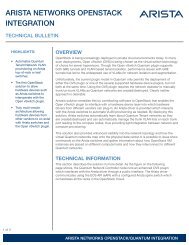
CHAPTER 5 <strong>Medianet</strong> Security Design Considerations 5-1<br />
An Introduction to Securing a <strong>Medianet</strong> 5-1<br />
<strong>Medianet</strong> Foundation Infrastructure 5-1<br />
<strong>Medianet</strong> Collaboration Services 5-2<br />
<strong>Cisco</strong> SAFE Approach 5-2<br />
Security Policy and Procedures 5-3<br />
Security of <strong>Medianet</strong> Foundation Infrastructure 5-3<br />
Security Architecture 5-3<br />
Network Foundation Protection 5-4<br />
Endpoint Security 5-5<br />
Web Security 5-6<br />
E-mail Security 5-6<br />
Network Access Control 5-7<br />
User Policy Enforcement 5-7<br />
Secure Communications 5-7<br />
Firewall Integration 5-8<br />
IPS Integration 5-8<br />
Telemetry 5-9<br />
Security of <strong>Medianet</strong> Collaboration Services 5-9<br />
Security Policy Review 5-10<br />
Architecture Integration 5-10<br />
Application of <strong>Cisco</strong> SAFE <strong>Guide</strong>lines 5-10<br />
<strong>Medianet</strong> Security <strong>Reference</strong> Documents 5-12<br />
CHAPTER 6 <strong>Medianet</strong> Management and Visibility Design Considerations 6-1<br />
Network-Embedded Management Functionality 6-2<br />
NetFlow 6-5<br />
NetFlow Strategies Within an Enterprise <strong>Medianet</strong> 6-6<br />
OL-22201-01<br />
<strong>Medianet</strong> <strong>Reference</strong> <strong>Guide</strong><br />
v
Contents<br />
NetFlow Collector Considerations 6-7<br />
NetFlow Export of Multicast Traffic Flows 6-9<br />
NetFlow Configuration Example 6-10<br />
<strong>Cisco</strong> Network Analysis Module 6-12<br />
NAM Analysis of Chassis Traffic 6-13<br />
NAM Analysis of NetFlow Traffic 6-15<br />
NAM Analysis of SPAN/RSPAN Traffic 6-22<br />
<strong>Cisco</strong> IP Service Level Agreements 6-24<br />
IPSLAs as a Pre-Assessment Tool 6-24<br />
IPSLA as an Ongoing Performance Monitoring Tool 6-32<br />
Router and Switch Command-Line Interface 6-35<br />
Traceroute 6-37<br />
show interface summary and show interface Commands 6-43<br />
Platform Specific Queue-Level Commands 6-45<br />
Simple Network Management Protocol 6-63<br />
Application-Specific Management Functionality 6-66<br />
<strong>Cisco</strong> TelePresence 6-66<br />
<strong>Cisco</strong> TelePresence Manager 6-70<br />
<strong>Cisco</strong> Unified Communications Manager 6-73<br />
<strong>Cisco</strong> TelePresence Multipoint Switch 6-75<br />
<strong>Cisco</strong> TelePresence System Endpoint 6-78<br />
<strong>Cisco</strong> TelePresence SNMP Support 6-80<br />
IP Video Surveillance 6-81<br />
Digital Media Systems 6-81<br />
Desktop Video Collaboration 6-81<br />
Summary 6-82<br />
CHAPTER 7 <strong>Medianet</strong> Auto Configuration 7-1<br />
Auto Smartports 7-1<br />
Platform Support 7-2<br />
Switch Configuration 7-3<br />
ASP Macro Details 7-7<br />
<strong>Medianet</strong> Devices with Built-in ASP Macros 7-9<br />
<strong>Cisco</strong> IPVS Cameras 7-9<br />
<strong>Cisco</strong> Digital Media Players (DMPs) 7-12<br />
<strong>Medianet</strong> Devices without Built-in ASP Macros 7-13<br />
<strong>Cisco</strong> TelePresence (CTS) Endpoints 7-13<br />
Other Video Conferencing Equipment 7-14<br />
Overriding Built-in Macros 7-14<br />
vi<br />
<strong>Medianet</strong> <strong>Reference</strong> <strong>Guide</strong><br />
OL-22201-01
Contents<br />
Macro-of-Last-Resort 7-18<br />
Custom Macro 7-20<br />
Security Considerations 7-22<br />
Authenticating <strong>Medianet</strong> Devices 7-23<br />
CDP Fallback 7-24<br />
Guest VLANs and LAST_RESORT Macro 7-24<br />
Verifying the VLAN Assignment on an Interface 7-25<br />
ASP with Multiple Attached CDP Devices 7-25<br />
Deployment Considerations 7-26<br />
Location Services 7-26<br />
Summary 7-28<br />
<strong>Reference</strong>s 7-29<br />
OL-22201-01<br />
<strong>Medianet</strong> <strong>Reference</strong> <strong>Guide</strong><br />
vii
Contents<br />
viii<br />
<strong>Medianet</strong> <strong>Reference</strong> <strong>Guide</strong><br />
OL-22201-01
CHAPTER<br />
1<br />
<strong>Medianet</strong> Architecture Overview<br />
Executive Summary<br />
Media applications—particularly video-oriented media applications—are exploding over corporate<br />
networks, exponentially increasing bandwidth utilization and radically shifting traffic patterns. There<br />
are several business drivers behind media application growth, including a globalized workforce, the<br />
pressure to go “green,” the transition to high-definition media (both in consumer and corporate markets)<br />
and social networking phenomena that are crossing over into the workplace. As a result, media<br />
applications are fueling a new wave of IP convergence, necessitating a fresh look at the network<br />
architecture.<br />
Converging media applications onto an IP network is much more complex than converging VoIP alone;<br />
this is not only because media applications are generally bandwidth-intensive and bursty (as compared<br />
to VoIP), but also because there are so many different types of media applications: beyond IP Telephony,<br />
these can include live and on-demand streaming media applications, digital signage applications,<br />
high-definition room-based conferencing applications as well as an infinite array of data-oriented<br />
applications. By embracing media applications as the next cycle of convergence, IT departments can<br />
think holistically about their network architecture and its readiness to support the coming tidal wave of<br />
media applications and develop a network-wide strategy to ensure high quality end-user experiences.<br />
Furthermore, thinking about your media application strategy now can help you take the first steps toward<br />
the next IP convergence wave and give your business competitive advantages, including the ability to<br />
harness the collective creativity and knowledge of your employees and to fundamentally change the<br />
experience your customers receive, all through the availability, simplicity and effectiveness of media<br />
applications.<br />
Additionally, media applications featuring video are quickly taking hold as the de facto medium for<br />
communication, supplementing virtually every other communication media. As a result, a significant<br />
portion of know-how and intellectual property is migrating into video mediums. It is critical to get ahead<br />
of this trend in order to maintain control of company assets and intellectual property.<br />
Offering both compelling media applications, like TelePresence and WebEx, as well as an end-to-end<br />
network design to support this next convergence wave, <strong>Cisco</strong> is in a unique position to provide a<br />
medianet architecture which can ensure the experience well into the collaborative workforce, enabling<br />
strategic and competitive advantage.<br />
High-level requirements of medianets are addressed, including availability and quality requirements,<br />
bandwidth and optimization requirements, and access control and security requirements. Following<br />
these, specific strategic recommendations in designing campus, WAN and branch, and data center<br />
medianets are presented.<br />
OL-22201-01<br />
<strong>Medianet</strong> <strong>Reference</strong> <strong>Guide</strong><br />
1-1
Business Drivers for Media Applications<br />
Chapter 1<br />
<strong>Medianet</strong> Architecture Overview<br />
Figure 1-1<br />
Media Applications<br />
Video<br />
Collaboration<br />
Digital Media<br />
Systems<br />
IP Video<br />
Surveillance<br />
TelePresence<br />
225089<br />
Business Drivers for Media Applications<br />
There are several business drivers behind media application growth, including a globalized workforce,<br />
the pressure to go green, the transition to high-definition media (both in consumer and corporate<br />
markets), and social networking phenomena that are crossing over into the workplace. These and other<br />
business drivers are discussed in additional detail below.<br />
Global Workforce and the Need for Real-Time Collaboration<br />
The first stage of productivity for most companies is acquiring and retaining the skilled and talented<br />
individuals in a single or few geographic locations. More recently the focus has been on finding<br />
technology solutions to enable a geographically-distributed workforce to collaborate together as a team,<br />
enabling companies more flexibly to harness talent “where it lives.” While this approach has been<br />
moderately successful, there is a new wave of productivity on the horizon: harnessing collective and<br />
collaborative knowledge.<br />
Future productivity gains will be achieved by creating collaborative teams that span corporate<br />
boundaries, national boundaries, and geographies. Employees will collaborate with partners, research<br />
and educational institutions, and customers to create a new level of collective knowledge.<br />
To do so, real-time multimedia collaboration applications will be absolutely critical to the success of<br />
these virtual teams. Video offers a unique medium which streamlines the effectiveness of<br />
communications between members of such teams. For this reason, real-time interactive video will<br />
become increasingly prevalent, as will media integrated with corporate communications systems.<br />
Pressures to be “Green”<br />
For many reasons, companies are seeking to reduce employee travel. Travel creates expenses to the<br />
bottom-line, as well as significant productivity impacts while employees are in-transit and away from<br />
their usual working environments. Many solutions have emerged to assist with productivity while<br />
traveling, including Wireless LAN hotspots, remote access VPNs, and softphones, all attempting to keep<br />
the employee connected while traveling.<br />
1-2<br />
<strong>Medianet</strong> <strong>Reference</strong> <strong>Guide</strong><br />
OL-22201-01
Chapter 1<br />
<strong>Medianet</strong> Architecture Overview<br />
Business Drivers for Media Applications<br />
More recently companies are under increasing pressures to demonstrate environmental responsibility,<br />
often referred to as being “green.” On the surface such initiatives may seem like a pop-culture trend, but<br />
lacking in tangible corporate returns. However, it is entirely possible to pursue “green” initiatives, while<br />
simultaneously increasing productivity and lowering expenses.<br />
Media applications, such as <strong>Cisco</strong> TelePresence, offer real solutions to remote collaboration challenges<br />
and have demonstrable savings as well. For example, during the first year of deployment, <strong>Cisco</strong><br />
measured its usage of TelePresence in direct comparison to the employee travel that would otherwise<br />
have taken place and found that over 80,000 hours of meetings were held by TelePresence instead of<br />
physical travel, avoiding $100 million of travel expenses, as well as over 30,000 tons of carbon<br />
emissions.<br />
Being “green” does not have to be a “tax;” it can improve productivity and reduce corporate expenses,<br />
offering many dimensions of return on investment, while at the same time sending significant messages<br />
to the global community of environmental responsibility.<br />
New Opportunities for IP Convergence<br />
Many advantages were achieved through the convergence of voice onto IP networks. In addition to cost<br />
savings, new communications applications were made possible by the integration of VoIP with other<br />
media applications on the IP network.<br />
There is a new wave of IP convergence emerging for media applications. One source of convergence is<br />
from applications historically having dedicated video transmission and broadcast networks. For<br />
example, high-definition video collaboration, video surveillance systems, and video advertising signage<br />
typically had dedicated private systems for the creation and dissemination of video content. Increasingly,<br />
companies are further leveraging the investment in their corporate network by converging these video<br />
applications onto a single IP network. <strong>Cisco</strong> TelePresence, <strong>Cisco</strong> IP video surveillance, and <strong>Cisco</strong><br />
Digital Media System products all make this convergence a reality.<br />
A second source of convergence is the integration of video as a medium into many other forms of<br />
corporate communications. For example, video cameras integrated with the VoIP system (such as <strong>Cisco</strong><br />
Unified Personal Communicator) provide an easy way to add video to existing VoIP calling patterns.<br />
Further, collaboration tools such as <strong>Cisco</strong> MeetingPlace and <strong>Cisco</strong> WebEx add video mediums as a<br />
capability for simple conferencing and real-time collaboration.<br />
Transition to High-Definition Media<br />
One of the reasons traditional room-to-room video conferencing and desktop webcam-style video<br />
conferencing are sometimes questioned as less than effective communications systems is the reliance on<br />
low-definition audio and video formats.<br />
On the other hand, high-definition interactive media applications, like <strong>Cisco</strong> TelePresence, demonstrate<br />
how high-definition audio and video can create an experience where meeting participants feel like they<br />
are in the same meeting room, enabling a more effective remote collaboration experience. IP video<br />
surveillance cameras are migrating to high-definition video in order to have digital resolutions needed<br />
for new functions, such as pattern recognition and intelligent event triggering based on motion and visual<br />
characteristics. <strong>Cisco</strong> fully expects other media applications to migrate to high-definition in the near<br />
future, as people become accustomed to the format in their lives as consumers, as well as the experiences<br />
starting to appear in the corporate environment.<br />
High-definition media formats transmitted over IP networks create unique challenges and demands on<br />
the network that need to be planned for. Demands including not only bandwidth, but also transmission<br />
reliability and low delay become critical issues to address.<br />
OL-22201-01<br />
<strong>Medianet</strong> <strong>Reference</strong> <strong>Guide</strong><br />
1-3
Business Drivers for Media Applications<br />
Chapter 1<br />
<strong>Medianet</strong> Architecture Overview<br />
Media Explosion<br />
Another factor driving the demand for video on IP networks is a sheer explosion of media content. The<br />
barriers to media production, distribution, and viewing have been dramatically lowered. For example,<br />
five to ten years ago video cameras became so affordable and prevalent that just about everyone bought<br />
one and became an amateur video producer. Additionally, video cameras are so common that almost<br />
every cell phone, PDA, laptop, and digital still camera provide a relatively high-quality video capture<br />
capability. However, until recently, it was not that easy to be a distributor of video content, as distribution<br />
networks were not common.<br />
Today, social networking sites like YouTube, MySpace and many others appearing every day have<br />
dramatically lowered the barrier to video publishing to the point where anyone can do it. Video editing<br />
software is also cheap and easy to use. Add to that a free, global video publishing and distribution<br />
system, and essentially anyone, anywhere can be a film studio. With little or no training, people are<br />
making movie shorts that rival those of dedicated video studios.<br />
The resulting explosion of media content is now the overwhelming majority of consumer network traffic,<br />
and is quickly “crossing over” to corporate networks. The bottom line is there are few barriers left to<br />
inhibit video communication, and so this incredibly effective medium is appearing in new and exciting<br />
applications every day.<br />
Social Networking—Not Just For Consumers Anymore<br />
Social networking started as a consumer phenomenon, with every day people producing and sharing rich<br />
media communications such as blogs, photos, and videos. When considering the affect it may have on<br />
corporate networks, some IT analysts believed social networking would stay as a consumer trend, while<br />
others believed the appearance in corporate networks was inevitable.<br />
Skeptics look at social networking sites like Myspace, YouTube and others and see them as fads<br />
primarily for the younger population. However, looking beyond the sites themselves it is important to<br />
understand the new forms of communication and information sharing they are enabling. For example,<br />
with consumer social networking typically people are sharing information about themselves, about<br />
subjects they have experience in, and interact with others in real-time who have similar interests. In the<br />
workplace, we already see the parallels happening, because the same types of communication and<br />
information sharing are just as effective.<br />
The corporate directory used to consist of employee names, titles, and phone numbers. Companies<br />
embracing social networking are adding to that skillsets and experience, URL links to shared work<br />
spaces, blogs, and other useful information. The result is a more productive and effective workforce that<br />
can adapt and find the skillsets and people needed to accomplish dynamic projects.<br />
Similarly, in the past information was primarily shared via text documents, E-mail, and slide sets.<br />
Increasingly, we see employees filming short videos to share best practices with colleagues, provide<br />
updates to peers and reports, and provide visibility into projects and initiatives. Why have social<br />
networking trends zeroed in on video as the predominant communication medium? Simple: video is the<br />
most effective medium. People can show or demonstrate concepts much more effectively and easily<br />
using video than any other medium.<br />
Just as a progression occurred from voice exchange to text, to graphics, and to animated slides, video<br />
will start to supplant those forms of communications. Think about the time it would take to create a good<br />
set of slides describing how to set up one of your company’s products. Now how much easier would it<br />
be just to film someone actually doing it? That's just one of many examples where video is supplanting<br />
traditional communication formats.<br />
1-4<br />
<strong>Medianet</strong> <strong>Reference</strong> <strong>Guide</strong><br />
OL-22201-01
Chapter 1<br />
<strong>Medianet</strong> Architecture Overview<br />
Business Drivers for Media Applications<br />
At <strong>Cisco</strong>, we have seen the cross-over with applications like <strong>Cisco</strong> Vision (C-Vision). Started as an<br />
ad-hoc service by several employees, C-Vision provides a central location for employees to share all<br />
forms of media with one another, including audio and video clips. <strong>Cisco</strong> employees share information<br />
on projects, new products, competitive practices, and many other subjects. The service was used by so<br />
many employees, <strong>Cisco</strong>’s IT department assumed ownership and scaled the service globally within<br />
<strong>Cisco</strong>. The result is a service where employees can become more effective and productive, quickly<br />
tapping into each other’s experience and know-how, all through the effectiveness and simplicity of video.<br />
Bottom-Up versus Top-Down Media Application Deployments<br />
Closely-related to the social-networking aspect of media applications is that users have increasingly<br />
driven certain types of media application deployments within the enterprise from the “bottom-up” (i.e.,<br />
the user base either demands or just begins to use a given media application with or without formal<br />
management or IT support). Such bottom-up deployments are illustrated by the <strong>Cisco</strong> C-Vision example<br />
mentioned in the previous section. Similar bottom-up deployment patterns have been noted for other<br />
Web 2.0 and multimedia collaboration applications.<br />
In contrast, company-sponsored video applications are pushed from the “top-down” (i.e., the<br />
management team decides and formally directs IT to support a given media application for their<br />
user-base). Such top-down media applications may include <strong>Cisco</strong> TelePresence, digital signage, video<br />
surveillance, and live broadcast video meetings.<br />
The combination of top-down and bottom-up media application proliferation places a heavy burden on<br />
the IT department as it struggles to cope with officially-supported and officially-unsupported, yet<br />
highly-proliferated, media applications.<br />
Multimedia Integration with Communications Applications<br />
Much like the integration of rich text and graphics into documentation, audio and video media will<br />
continue to be integrated into many forms of communication. Sharing of information with E-mailed slide<br />
sets will start to be replaced with video clips. The audio conference bridge will be supplanted with the<br />
video-enabled conference bridge. Collaboration tools designed to link together distributed employees<br />
will increasingly integrate desktop video to bring teams closer together.<br />
<strong>Cisco</strong> WebEx is a prime example of such integration, providing text, audio, instant messaging,<br />
application sharing, and desktop video conferencing easily to all meeting participates, regardless of their<br />
location. Instead of a cumbersome setup of a video conference call, applications such as <strong>Cisco</strong> Unified<br />
Personal Communicator and <strong>Cisco</strong> WebEx greatly simplify the process, and video capability is added to<br />
the conference just as easily as any other type of media, like audio.<br />
Demand for Universal Media Access<br />
Much like the mobile phone and wireless networking, people want to extend communications<br />
everywhere they want to use them. The mobile phone unwired audio, making voice communications<br />
accessible virtually anywhere on the planet. Wireless networking untethered the laptop and PDA,<br />
extending high-speed data communications to nearly everywhere and many different devices.<br />
Media applications will follow the same model. As multimedia applications become increasingly<br />
utilized and integrated, the demands from users will be to access these applications wherever they are,<br />
and on their device of choice. These demands will drive the need for new thinking about how employees<br />
work and how to deliver IT services to them.<br />
OL-22201-01<br />
<strong>Medianet</strong> <strong>Reference</strong> <strong>Guide</strong><br />
1-5
Challenges of <strong>Medianet</strong>s<br />
Chapter 1<br />
<strong>Medianet</strong> Architecture Overview<br />
Today employees extend the workplace using mobile phones and wireless networking to home offices,<br />
airports, hotels, and recreation venues. But, for example, with increased reliance on video as a<br />
communication medium, how will video be extended to these same locations and with which devices?<br />
We already see the emergence of video clips filmed with mobile phones and sent to friends and<br />
colleagues. Participation in video conferencing, viewing the latest executive communications, and<br />
collaborating with co-workers will need to be accessible to employees, regardless of their work location.<br />
Challenges of <strong>Medianet</strong>s<br />
There are a number of challenges in designing an IP network with inherent support for the limitless<br />
number of media applications, both current and future. The typical approach followed is to acquire a<br />
media application, like IP Video Conferencing, make the network improvements and upgrades needed<br />
to deliver that specific application, and then monitor the user feedback. While a good way to implement<br />
a single application, the next media application will likely require the same process, and repeated efforts,<br />
and often another round of network upgrades and changes.<br />
A different way to approach the challenge is to realize up-front that there are going to be a number of<br />
media applications on the network, and that these applications are likely to start consuming the majority<br />
of network resources in the future. Understanding the collection of these applications and their common<br />
requirements on the network can lead to a more comprehensive network design, better able to support<br />
new media applications as they are added. This design is what we term the medianet.<br />
Considerations for the medianet include media delivery, content management, client access and security,<br />
mobility, as well as integration with other communications systems and applications.<br />
Understanding Different Media Application Models<br />
Different media applications will behave differently and put different requirements on the network. For<br />
example, <strong>Cisco</strong> TelePresence has relatively high bandwidth requirements (due to the HD video streams<br />
being transmitted) and tight tolerances for delivery. Traffic patterns are somewhat predictable, due to the<br />
room-to-room calling characteristics. In contrast, <strong>Cisco</strong> Digital Signage typically has less stringent<br />
delivery tolerances, and the traffic flows are from a central location (or locations) out towards several or<br />
many endpoints (see Figure 1-2).<br />
1-6<br />
<strong>Medianet</strong> <strong>Reference</strong> <strong>Guide</strong><br />
OL-22201-01
Chapter 1<br />
<strong>Medianet</strong> Architecture Overview<br />
Challenges of <strong>Medianet</strong>s<br />
Figure 1-2<br />
Understanding Media Application Behavior Models<br />
Model<br />
Direction of Flows<br />
Traffic Trends<br />
TelePresence<br />
Many to<br />
Many<br />
Client ← → Client<br />
MCU ← → Client<br />
High-def video requires up to 4-12Mbps<br />
per location<br />
Expansion down to the individual user<br />
Streaming Interactive<br />
Desktop<br />
Multimedia<br />
Conferencing<br />
Video<br />
Surveillance<br />
Desktop<br />
Streaming<br />
Media and<br />
Digital Signage<br />
Many to<br />
Many<br />
Many to<br />
Few<br />
Few to<br />
Many<br />
Client ← → Client<br />
MCU ← → Client<br />
Source → Storage<br />
Storage → Client<br />
Source → Client<br />
Storage → Client<br />
Source → Client<br />
Collaboration across geographies<br />
Growing peer -to-peer model driving<br />
higher on -demand bandwidth<br />
IP convergence opening up usage and<br />
applications<br />
Higher quality video requirements driving<br />
higher bandwidth (up to 3-4Mbps per<br />
camera)<br />
Tremendous increase in applications<br />
driving more streams<br />
Demand for higher quality video increases<br />
each stream<br />
224514<br />
The four media applications shown in Figure 1-2 cover a significant cross-section of models of media<br />
application behavior. To include additional applications in the inventory, critical questions to consider<br />
include:<br />
• Is the media stored and viewed (streaming) or real-time (interactive)?<br />
• Where are the media sources and where are the viewers?<br />
• Which direction do the media flows traverse the network?<br />
• How much bandwidth does the media application require? And how much burst?<br />
• What are the service level tolerances (in terms of latency, jitter and loss)?<br />
• What are the likely media application usage patterns?<br />
• Are there requirements to connect to other companies (or customers)?<br />
• In what direction is the media application likely to evolve in the future?<br />
With a fairly straightforward analysis, it is possible to gain tremendous understanding into the network<br />
requirements various media applications.<br />
One important consideration is: where is/are the media source(s) and where is/are the consumer(s)? For<br />
example, with desktop multimedia conferencing, the sources and consumers are both the desktop;<br />
therefore, the impacts to the network are very likely to be within the campus switching network, across<br />
the WAN/VPN, and the branch office networks. Provisioning may be challenging, as the ad-hoc<br />
conference usage patterns may be difficult to predict; however, voice calling patterns may lend insight<br />
into likely media conferencing calling patterns.<br />
To contrast, the sources of on-demand media streams are typically within the data center, from<br />
high-speed media servers. Because viewers can be essentially any employee, this will affect the campus<br />
switching network, the WAN/VPN, the branch offices, and possibly even remote teleworkers. Since there<br />
will may be many simultaneous viewers, it would be inefficient to duplicate the media stream to each<br />
viewer; so wherever possible, we would like to take advantage of broadcast optimization technologies.<br />
OL-22201-01<br />
<strong>Medianet</strong> <strong>Reference</strong> <strong>Guide</strong><br />
1-7
Challenges of <strong>Medianet</strong>s<br />
Chapter 1<br />
<strong>Medianet</strong> Architecture Overview<br />
In these simplistic examples, you can see why it is important to understand how different media<br />
applications behave in order to understand how they are likely to impact your network. Start by making<br />
a table with (at least) the above questions in mind and inventory the various media applications in use<br />
today, as well as those being considered for future deployments. Common requirements will emerge,<br />
such as the need to meet “tight” service levels, the need to optimize bandwidth, and the need to optimize<br />
broadcasts, which will be helpful in determining media application class groupings (discussed in more<br />
detail later).<br />
Delivery of Media Applications<br />
A critical challenge the converged IP network needs to address is delivery of media application traffic,<br />
in a reliable manner, while achieving the service levels required by each application. Media applications<br />
inherently consume significant amounts of network resources, including bandwidth. A common<br />
tendency is to add network bandwidth to existing IP networks and declare them ready for media<br />
applications; however, bandwidth is just one factor in delivering media applications.<br />
Media applications, especially those which are real-time or interactive, require reliable networks with<br />
maximum up-time. For instance, consider the loss sensitivities of VoIP compared to high-definition<br />
media applications, such as HD video. For a voice call, a packet loss percentage of even 1% can be<br />
effectively concealed by VoIP codecs; whereas, the loss of two consecutive VoIP packets will cause an<br />
audible “click” or “pop” to be heard by the receiver. In stark contrast, however, video-oriented media<br />
applications generally have a much greater sensitivity to packet loss, especially HD video applications,<br />
as these utilize highly-efficient compression techniques, such as H.264. As a result, a tremendous<br />
amount of visual information is represented by a relatively few packets, which if lost, immediately<br />
become visually apparent in the form of screen pixelization. With such HD media applications, such as<br />
<strong>Cisco</strong> TelePresence, the loss of even one packet in 10,000 can be noticed by the end user. This represents<br />
a hundred-fold increase in loss sensitivity when VoIP is compared to HD video.<br />
Therefore, for each media application, it is important to understand the delivery tolerances required in<br />
order to deliver a high-quality experience to the end user.<br />
Prioritizing the Right Media Applications, Managing the Rest<br />
With the first stage of IP convergence, the <strong>Cisco</strong> Architecture for Voice, Video, and Integrated Data<br />
(AVVID) provided the foundation for different applications to effectively and transparently share the<br />
same IP network. One of the challenges to overcome with converged networks is to be able to<br />
simultaneously meet different application requirements, prioritizing network resources accordingly.<br />
Quality of Service (QoS) continues to be a critical set of functions relied upon in the network to provide<br />
differentiated service levels, assuring the highest priority applications can meet their delivery<br />
requirements.<br />
The AVVID model defined best practices for adding Voice-over-IP (VoIP) and Video over IP<br />
applications to the existing data IP network. Most QoS implementations assume a number of data<br />
applications, a single or few VoIP applications, and a single or few video applications.<br />
Today there is a virtual explosion of media applications on the IP network with many different<br />
combinations of audio, video and data media. For example, VoIP streams can be standard IP telephony,<br />
high-definition audio, internet VoIP, or others. Video streams can range from relatively low-definition<br />
webcams to traditional video-over-IP room-to-room conferencing to or high-definition <strong>Cisco</strong><br />
TelePresence systems. Additionally, there are new IP convergence opportunities occurring which further<br />
expand the number of media applications and streams on the IP network (see Figure 1-3).<br />
1-8<br />
<strong>Medianet</strong> <strong>Reference</strong> <strong>Guide</strong><br />
OL-22201-01
Chapter 1<br />
<strong>Medianet</strong> Architecture Overview<br />
Challenges of <strong>Medianet</strong>s<br />
Another source of new media streams on the network is “unmanaged” media applications; namely,<br />
applications which are considered primarily for consumers, but are also used by corporate employees.<br />
Many of these unmanaged media applications may fall into a gray area for some companies in terms of<br />
usage policies. For instance, at first glance, consumer media sharing sites such as YouTube may appear<br />
to be clearly consumer-only applicability; however, many of these same services also contain videos that<br />
can provide considerable know-how and information that are useful to employees as well.<br />
Figure 1-3<br />
Media Explosion Driving New Convergence Evolution<br />
Data Convergence Media Explosion Collaborative M<br />
Video<br />
Voice<br />
• Interactive Video<br />
• Streaming Video<br />
• IP Telephony<br />
Unmanaged<br />
Applications<br />
Video<br />
Voice<br />
• Internet Streaming<br />
• Internet VoIP<br />
• YouTube<br />
• MySpace<br />
• Other<br />
• Desktop Streaming Video<br />
• Desktop Broadcast Video<br />
• Digital Signage<br />
• IP Video Surveillance<br />
• Desktop Video Conferencing<br />
• HD Video<br />
• IP Telephony<br />
• HD Audio<br />
• SoftPhone<br />
• Other VoIP<br />
Ad-Hoc App<br />
Data<br />
Apps<br />
• App Sharing<br />
• Web/Internet<br />
• Messaging<br />
• Email<br />
Data<br />
Apps<br />
• App Sharing<br />
• Web/Internet<br />
• Messaging<br />
• Email<br />
Data<br />
Apps<br />
• App Sharing<br />
• Web/Internet<br />
• Messaging<br />
• Email<br />
Beyond the current “media explosion” which is driving a new wave of IP convergence, new and exciting<br />
applications targeted at collaboration are integrating numerous types of streams and media into end-user<br />
applications. <strong>Cisco</strong> TelePresence is one example, combining HD video streams, HD audio, application<br />
sharing, and some level of interoperability with traditional video conferencing, into an overall<br />
collaboration tool and near in-person meeting experience. <strong>Cisco</strong> WebEx is another example, combining<br />
many types of media sharing for web-based meetings. Such applications provide new challenges for<br />
prioritizing media application streams.<br />
The explosion of media content, types and applications—both managed and unmanaged—requires<br />
network architects to take a new look at their media application provisioning strategy. Without a clear<br />
strategy, the number and volume of media applications on the IP network could very well exceed the<br />
ability of the network administrator to provision and manage.<br />
Media Application Integration<br />
As media applications increase on the IP network, integration will play a key role in two ways: first,<br />
media streams and endpoints will be increasingly leveraged by multiple applications. For example,<br />
desktop video endpoints may be leveraged for desktop video conferencing, web conferencing, and for<br />
viewing stored streaming video for training and executive communications.<br />
OL-22201-01<br />
<strong>Medianet</strong> <strong>Reference</strong> <strong>Guide</strong><br />
1-9
Solution<br />
Chapter 1<br />
<strong>Medianet</strong> Architecture Overview<br />
Second, many media applications will require common sets of functions, such as transcoding, recording,<br />
and content management. To avoid duplication of resources and higher implementation costs, common<br />
media services need to be integrated into the IP network so they can be leveraged by multiple media<br />
applications.<br />
Securing Media Applications<br />
Because of the effectiveness of multimedia communication and collaboration, the security of media<br />
endpoints and communication streams becomes an important part of the media-ready strategy. Access<br />
controls for endpoints and users, encryption of streams, and securing content files stored in the data<br />
center are all part of a required comprehensive media application security strategy.<br />
Other specialized media applications, such as IP video surveillance and digital signage, may warrant<br />
additional security measures due to their sensitivity and more restricted user group. Placing such media<br />
applications within private logical networks within the IP network can offer an additional layer of<br />
security to keep their endpoints and streams confidential.<br />
Finally, as the level of corporate intellectual property migrates into stored and interactive media, it is<br />
critical to have a strategy to manage the media content, setting and enforcing clear policies, and having<br />
the ability to protect intellectual property in secure and managed systems. Just as companies have<br />
policies and processes for handling intellectual property in document form, they also must develop and<br />
update these policies and procedures for intellectual property in media formats.<br />
Solution<br />
The Need for a Comprehensive Media Network Strategy<br />
It is possible to pursue several different strategies for readying the IP network for media applications.<br />
One strategy is to embrace media applications entirely, seeing these technologies as driving the next<br />
wave of productivity for businesses. Another strategy is to adopt a stance to manage and protect select<br />
media applications on the network. Still another strategy would be to not manage media applications at<br />
all. Which strategy should you pursue?<br />
If we have learned anything from past technology waves which enable productivity, it is this: if corporate<br />
IT does not deploy (or lags significantly in deployment) users will try to do it themselves... and usually<br />
poorly. For example, several years ago, some IT departments were skeptical of the need to deploy<br />
Wireless LANs (WLANS) or questioned-and rightly so-their security. As a result, many WLAN<br />
deployments lagged. Users responded by purchasing their own consumer-grade WLAN access-points<br />
and plugging them into corporate networks, creating huge holes in the network security strategy. Such<br />
“rogue” access-points in the corporate network, lacking proper WLAN security, not only represented<br />
critical security vulnerabilities to the network as a whole, but also were difficult for network<br />
administrators to locate and shut down.<br />
The coming media application wave will be no different and is already happening. IT departments<br />
lacking a media application strategy may find themselves in the future trying to regain control of traffic<br />
on the network. It is advantageous to define a comprehensive strategy now for how media applications<br />
will be managed on the network. Key questions the strategy should answer include:<br />
• Which are the business-critical media applications? And what service levels must be ensured for<br />
these applications?<br />
• Which media applications will be managed or left unmanaged?<br />
1-10<br />
<strong>Medianet</strong> <strong>Reference</strong> <strong>Guide</strong><br />
OL-22201-01
Chapter 1<br />
<strong>Medianet</strong> Architecture Overview<br />
Solution<br />
• What will the usage policies be and how will they be enforced?<br />
As mentioned earlier, one approach to planning the network is to assess the network upgrades and<br />
changes required for each new media application deployed by the company. This approach could lead to<br />
a lot of repeated effort and change cycles by the IT staff and potentially incompatible network designs.<br />
A more efficient and far-sighted approach would be to consider all the types of media applications the<br />
company is currently using—or may use in the future—and design a network-wide architecture with<br />
media services in mind.<br />
Architecture of a <strong>Medianet</strong><br />
A medianet is built upon an architecture that supports the different models of media applications and<br />
optimizes their delivery, such as those shown in the architectural framework in Figure 1-4.<br />
Figure 1-4<br />
Architectural Framework of a <strong>Medianet</strong><br />
Clients<br />
<strong>Medianet</strong> Services<br />
Media Endpoint<br />
Session Control Services<br />
Media<br />
Content<br />
Call Agent(s)<br />
Session/Border Controllers<br />
Gateways<br />
User<br />
Interface<br />
Codec<br />
Media I/O<br />
Access Services<br />
Identity Services<br />
Confidentiality<br />
Mobility Services<br />
Location/Context<br />
Transport Services<br />
Packet Delivery<br />
Quality of Service<br />
Session Admission<br />
Optimization<br />
Bridging Services<br />
Conferencing<br />
Transcoding<br />
Recording<br />
Storage Services<br />
Capture/Storage<br />
Content Mgmt<br />
Distribution<br />
IP<br />
High Availability Network Design<br />
MAN/WAN, Metro<br />
Branch Ethernet, SONET, Campus Data Center<br />
DWDM/CWDM<br />
224516<br />
A medianet framework starts with and end-to-end network infrastructure designed and built to achieve<br />
high availability, including the data center, campus, WAN, and branch office networks. The network<br />
provides a set of services to video applications, including:<br />
• Access services—Provide access control and identity of video clients, as well as mobility and<br />
location services<br />
• Transport services—Provide packet delivery, ensuring the service levels with QoS and delivery<br />
optimization<br />
• Bridging services—Transcoding, conferencing, and recording services<br />
• Storage services—Content capture, storage, retrieval, distribution, and management services<br />
OL-22201-01<br />
<strong>Medianet</strong> <strong>Reference</strong> <strong>Guide</strong><br />
1-11
Solution<br />
Chapter 1<br />
<strong>Medianet</strong> Architecture Overview<br />
• Session control services—Signaling and control to setup and tear-down sessions, as well as<br />
gateways<br />
When these media services are made available within the network infrastructure, endpoints can be<br />
multi-purpose and rely upon these common media services to join and leave sessions for multiple media<br />
applications. Common functions such as transcoding and conferencing different media codecs within the<br />
same session can be deployed and leveraged by multiple applications, instead of being duplicated for<br />
each new media application.<br />
Where these different services are deployed within the network can also be customized for different<br />
business models or media applications. For example, it may be advantageous to store all IP video<br />
surveillance feeds centrally in the data center, or for some companies it may be preferable to have<br />
distributed storage in branch office networks.<br />
Common Requirements and Recommendations<br />
After understanding the behavior of the different media applications in the network, there are common<br />
threads of requirements that can be derived. The top recommendations based on these common<br />
requirements are discussed in the follow subsections.<br />
Network Design for High Availability<br />
Data applications are tolerant of multi-second interruptions, while VoIP and video applications require<br />
tighter delivery requirements in order to achieve high quality experiences for the end users. Networks<br />
that have already implemented higher availability designs with VoIP convergence in mind are a step<br />
ahead.<br />
Loss of packets, whether due to network outage or other cause, necessitates particular attention for media<br />
applications, especially those that require extreme compression. For example, HD video, would require<br />
billions of bytes to be transmitted over the IP network and is not practically deployable without efficient<br />
compression schemes like MPEG4 or H.264. To illustrate this point, consider a high-definition 1080p30<br />
video stream, such as used by <strong>Cisco</strong> TelePresence systems. The first parameter “1080” refers to 1080<br />
lines of horizontal resolution, which are matrixed with 1920 lines of vertical resolution (as per the 16:9<br />
Widescreen Aspect Ratio used in High Definition video formatting), resulting in 2,073,600 pixels per<br />
screen. The second parameter “p” indicates a progressive scan, which means that every line of resolution<br />
is refreshed with each frame (as opposed to an interlaced scan, which would be indicated with an “i” and<br />
would mean that every other line is refreshed with each frame). The third parameter “30” refers to the<br />
transmission rate of 30 frames per second. While video sampling techniques may vary, each pixel has<br />
approximately 3 Bytes of color and/or luminance information. When all of this information is factored<br />
together (2,073,600 pixels x 3 Bytes x 8 bits per Byte x 30 frames per second), it results in approximately<br />
1.5 Gbps of information. However, H.264-based <strong>Cisco</strong> TelePresence codecs transmit this information at<br />
approximately 5 Mbps (maximum), which translates to over 99% compression. Therefore, the overall<br />
effect of packet loss is proportionally magnified, such that dropping even one packet in 10,000 (0.01%<br />
packet loss) is noticeable to end users in the form of minor pixelization. This is simply because a single<br />
packet represents a hundred or more packets’ worth of information, due to the extreme compression<br />
ratios applied, as illustrated in Figure 1-5.<br />
1-12<br />
<strong>Medianet</strong> <strong>Reference</strong> <strong>Guide</strong><br />
OL-22201-01
Chapter 1<br />
<strong>Medianet</strong> Architecture Overview<br />
Solution<br />
Figure 1-5<br />
Compression Ratios for HD Video Applications<br />
1920 lines of Vertical Resolution (Widescreen Aspect Ratio is 16:9)<br />
1080 lines of Horizontal Resolution<br />
2,073,600 pixels per frame<br />
x 3 Bytes of color info per pixel<br />
x 8 bits per Byte<br />
x 30 frames per second<br />
= 1.5 Gbps per screen (uncompressed)<br />
A resulting stream of 5 Mbps represents an applied compression ratio of 99%+<br />
Traditional network designs supporting data applications may have targeted packet loss at less than<br />
1-2%. For VoIP, network designs were tightened to have only 0.5-1% of packet loss. For media-ready<br />
networks, especially those supporting high-definition media applications, network designs need to be<br />
tightened again by an order of magnitude, targeting 0-0.05% packet loss.<br />
However, an absolute target for packet loss is not the only consideration in HA network design. Loss,<br />
during normal network operation, should effectively be 0% on a properly-designed network. In such a<br />
case, it is generally only during network events, such as link failures and/or route-flaps, that packet loss<br />
would occur. Therefore, it is usually more meaningful to express availability targets not only in absolute<br />
terms, such as
Solution<br />
Chapter 1<br />
<strong>Medianet</strong> Architecture Overview<br />
To summarize: the targets for media-ready campus and data center networks in terms of packet loss is<br />
0.05% with a network convergence target of 200 ms; on WAN and branch networks, loss should still be<br />
targeted to 0.05%, but convergence targets will be higher depending on topologies, service providers,<br />
and other constraints. Finally, it should be noted that by designing the underlying network architecture<br />
for high availability, all applications on the converged network benefit.<br />
Bandwidth and Burst<br />
There is no way around the fact that media applications require significant network bandwidth. An<br />
important step to implement a medianet is to assess current and future bandwidth requirements across<br />
the network. Consider current bandwidth utilization and add forecasts for media applications, especially<br />
for video-oriented media applications. Because video is in a relatively early stage of adoption, use<br />
aggressive estimates of possible bandwidth consumption. Consider bandwidth of different entry and<br />
transit points in the network. What bandwidth is needed at network access ports both in the campus as<br />
well as branch offices? What are the likely media streams needing transport across the WAN?<br />
It is important to consider all types of media applications. For example, how many streaming video<br />
connections will be utilized for training and communications? These typically flow from a central point,<br />
such as the data center, outward to employees in campus and branch offices. As another example, how<br />
many IP video surveillance cameras will exist on the network? These traffic flows are typically from<br />
many sources at the edges of the network inward toward central monitoring and storage locations.<br />
Map out the media applications that will be used, considering both managed and un-managed<br />
applications. Understand the bandwidth required by each stream and endpoint, as well as the direction(s)<br />
in which the streams will flow. Mapping those onto the network can lead to key bandwidth upgrade<br />
decisions at critical places in the network architecture, including campus switching as well as the WAN.<br />
Another critical bandwidth-related concern is burst. So far, we have discussed bandwidth in terms of bits<br />
per second (i.e., how much traffic is sent over a one second interval); however, when provisioning<br />
bandwidth, burst must also be taken into account. Burst is defined as the amount of traffic (generally<br />
measured in Bytes) transmitted per millisecond which exceeds the per-second average.<br />
For example, a <strong>Cisco</strong> TelePresence 3000 system may average 15 Megabits per second, which equates to<br />
an average per millisecond rate of 1,875 Bytes (15 Mbps ÷ 1,000 milliseconds ÷ 8 bits per Byte). <strong>Cisco</strong><br />
TelePresence operates at 30 frames per second, which means that every 33 ms a video frame is<br />
transmitted. Each frame consists of several thousand Bytes of video payload, and therefore each frame<br />
interval consists of several dozen packets, with an average packet size of 1,100 bytes per packet.<br />
However, because video is variable in size (due to the variability of motion in the encoded video), the<br />
packets transmitted by the codec are not spaced evenly over each 33 ms frame interval, but rather are<br />
transmitted in bursts measured in shorter intervals. Therefore, while the overall bandwidth (maximum)<br />
averages out to 15 Mbps over one second, when measured on a per millisecond basis, the packet<br />
transmission rate is highly variable, and the number of Bytes transmitted per millisecond for a 15 Mbps<br />
stream can burst well above the 1,875 Bytes per millisecond average. Therefore, adequate burst tolerance<br />
must be accommodated by all switch and router interfaces in the path.<br />
Given these considerations, it can be noted that converging voice onto a common IP-based network is a<br />
significantly simpler exercise than converging video onto the same network. The principle reason is that<br />
VoIP is a very well-behaved application, from a networking perspective. For instance, each VoIP packet<br />
size is known and constant (for example, G.711 codecs generate packets that are always 160 Bytes [+<br />
Layer 2 overhead]); similarly, VoIP packetization rates are known and constant (the default packetization<br />
rate for VoIP is 50 packet-per-second, which produces a packet every 20 ms). Furthermore, VoIP has very<br />
light bandwidth requirements (as compared to video and data) and these requirements can be very<br />
cleanly calculated by various capacity planning formulas (such as Erlang and Endset formulas).<br />
1-14<br />
<strong>Medianet</strong> <strong>Reference</strong> <strong>Guide</strong><br />
OL-22201-01
Chapter 1<br />
<strong>Medianet</strong> Architecture Overview<br />
Solution<br />
In contrast, video is a completely different type of application in almost every way. Video packet sizes<br />
vary significantly and video packetization rates also vary significantly (both in proportion to the amount<br />
of motion in the video frames being encoded and transmitted); furthermore, video applications are<br />
generally quite bursty—especially during sub-second intervals—and can wreak havoc on<br />
underprovisioned network infrastructures. Additionally, there are no clean formulas for provisioning<br />
video, as there are with VoIP. This contrast—from a networking perspective—between voice and video<br />
traffic is illustrated in Figure 1-6<br />
Figure 1-6<br />
Sub-Second Bandwidth Analysis—Voice versus Video<br />
1400<br />
Voice Packets<br />
1400<br />
Video<br />
Frame<br />
Video Packets<br />
Video<br />
Frame<br />
Video<br />
Frame<br />
1000<br />
1000<br />
Bytes<br />
600<br />
Audio<br />
Samples<br />
600<br />
200<br />
200<br />
20 msec Time 33 msec<br />
224376<br />
Summing up, converging media applications-especially video-based media applications-onto the IP<br />
network is considerably more complex than converging voice and data, due to the radically different<br />
bandwidth and burst requirements of video compared to voice. While deployment scenarios will vary, in<br />
most cases, capacity planning exercises will indicate that Campus and Data Center medianets will<br />
require GigabitEthernet (GE) connections at the edge and 10 GigabitEthernet (10GE) connections-or<br />
multiples thereof-in the core; additionally, medianets will likely have a minimum bandwidth requirement<br />
of 45 Mbps/DS3 circuits. Furthermore, network administrators not only have to consider the bandwidth<br />
requirements of applications as a function of bits-per-second, but also they must consider the burst<br />
requirements of media, such as video, as a function of Bytes-per-millisecond, and ensure that the routers<br />
and switches have adequate buffering capacity to handle bursts.<br />
Latency and Jitter<br />
Media applications, particularly interactive media applications, have strict requirements for network<br />
latency. Network latency can be broken down further into fixed and variable components:<br />
• Serialization (fixed)<br />
OL-22201-01<br />
<strong>Medianet</strong> <strong>Reference</strong> <strong>Guide</strong><br />
1-15
Solution<br />
Chapter 1<br />
<strong>Medianet</strong> Architecture Overview<br />
• Propagation (fixed)<br />
• Queuing (variable)<br />
Serialization refers to the time it takes to convert a Layer 2 frame into Layer 1 electrical or optical pulses<br />
onto the transmission media. Therefore, serialization delay is fixed and is a function of the line rate (i.e.,<br />
the clock speed of the link). For example, a 45 Mbps DS3 circuit would require 266 μs to serialize a 1500<br />
byte Ethernet frame onto the wire. At the circuit speeds required for medianets (generally speaking DS3<br />
or higher), serialization delay is not a significant factor in the overall latency budget.<br />
The most significant network factor in meeting the latency targets for video is propagation delay, which<br />
can account for over 95% of the network latency budget. Propagation delay is also a fixed component<br />
and is a function of the physical distance that the signals have to travel between the originating endpoint<br />
and the receiving endpoint. The gating factor for propagation delay is the speed of light: 300,000 km/s<br />
or 186,000 miles per second. Roughly speaking, the speed of light in an optical fiber is about one-sixth<br />
the speed of light in a vacuum. Thus, the propagation delay works out to be approximately 4-6 μs per<br />
km (or 6.4-9.6 μs per mile) 1 .<br />
Another point to keep in mind when calculating propagation delay is that optical fibers and coaxial<br />
cables are not always physically placed over the shortest path between two geographic points, especially<br />
over transoceanic links. Due to installation convenience, circuits may be hundreds or thousands of miles<br />
longer than theoretically necessary.<br />
The network latency target specified in the ITU G.114 specification for voice and video networks is 150<br />
ms. This budget allows for nearly 24,000 km (or 15,000 miles) worth of propagation delay (which is<br />
approximately 60% of the earth’s circumference); the theoretical worst-case scenario (exactly half of the<br />
earth’s circumference) would require 120 ms of latency. Therefore, this latency target (of 150 ms) should<br />
be achievable for virtually any two locations on the planet, given relatively direct transmission paths.<br />
Nonetheless, it should be noted that overall quality does not significantly degrade for either voice of<br />
video calls until latency exceeds 200 ms, as shown in Figure 1-7 (taken from ITU G.114).<br />
1. Per ITU G.114 Table 4.1: The transmission speeds of terrestrial coaxial cables is 4 μs /km, of optical fiber<br />
cable systems with digital transmission is 5 μs / km, and of submarine coaxial cable systems is 6 μs /km<br />
(allowing for delays in repeaters and regenerators).<br />
1-16<br />
<strong>Medianet</strong> <strong>Reference</strong> <strong>Guide</strong><br />
OL-22201-01
Chapter 1<br />
<strong>Medianet</strong> Architecture Overview<br />
Solution<br />
Figure 1-7<br />
Network Latency versus Call Quality<br />
Network Latency Target for Voice and Interactive-Video (150 ms)<br />
Network Latency Threshold for Voice and Interactive-Video (200 ms)<br />
100<br />
90<br />
E-model rating R<br />
80<br />
70<br />
60<br />
50<br />
80 100 200 300 400 500<br />
Mouth-to-ear-delay/ms<br />
224549<br />
The final network latency component to be considered is queuing delay, which is variable. Variance in<br />
network latency is also known as jitter. For instance, if the average latency is 100 ms and packets are<br />
arriving between 95 ms and 105 ms, the peak-to-peak jitter is defined as 10 ms. Queuing delay is the<br />
primary cause of jitter and is a function of whether a network node is congested or not, and if it is, what<br />
scheduling policies (if any) have been configured to manage congestion. For interactive media<br />
applications, packets that are excessively late (due to network jitter) are no better than packets that have<br />
been lost. Media endpoints usually have a limited amount of playout-buffering capacity to offset jitter.<br />
However, in general, it is recommended that jitter for real-time interactive media applications not exceed<br />
10 ms peak-to-peak.<br />
To recap: the one-way latency target for interactive media applications is 150 ms (with a threshold limit<br />
of 200 ms). Additionally, since the majority of factors contributing to the latency budget are fixed,<br />
careful attention has to be given to queuing delay, as this is the only latency/jitter factor that is directly<br />
under the network administrator’s control (via QoS queuing policies, which are discussed in the next<br />
section, Application Intelligence and Quality of Service).<br />
Application Intelligence and Quality of Service<br />
Implementation of a comprehensive QoS strategy requires the ability to identify the business critical<br />
media applications and set a QoS service policy to mark and service such traffic. With the dramatic<br />
increase in types of media applications and streams, it becomes increasingly difficult to identify the<br />
critical media application streams from those that are considered unimportant. Streams using similar<br />
codecs may have similar packet construction and be difficult to classify using IP packet header<br />
information alone.<br />
OL-22201-01<br />
<strong>Medianet</strong> <strong>Reference</strong> <strong>Guide</strong><br />
1-17
Solution<br />
Chapter 1<br />
<strong>Medianet</strong> Architecture Overview<br />
Therefore, packet classification needs to evolve to utilize deeper packet inspection technologies in order<br />
to have the granularity needed to distinguish between different types of media streams. Developing<br />
additional application intelligence within the network infrastructure is a crucial requirement to build a<br />
medianet, especially at the edges of the network where media endpoints first handoff packets into the<br />
network for transport.<br />
Additionally, there are advantages of being able to perform media application sub-component<br />
separation, such that data components of a media application receive one level of service, whereas the<br />
audio and video components of the same application receive a different level of service 1 . Such separation<br />
can simplify bandwidth provisioning, admission control, and capacity planning. That being said, media<br />
application sub-component separation more often than not requires deep packet inspection technologies,<br />
especially for media applications that are transported entirely within HTTP.<br />
An alternative approach that presents another consideration is whether to trust media endpoints to mark<br />
their own traffic or not. Typically such endpoints can mark at Layer 2 (via 802.1Q/p CoS) or at Layer 3<br />
(DSCP). Key factors the administrator needs to consider is how secure is the marking? Is it the marking<br />
centrally administered or locally set? Can it be changed or exploited by the end users? While trusting<br />
the endpoints to correctly mark themselves may simplify the network edge policies, it could present<br />
security vulnerabilities that could be inadvertently or deliberately exploited. In general, hardware-based<br />
media endpoints (such as dedicated servers, cameras, codecs, and gateways) are more “trustworthy,”<br />
whereas software-based media endpoints (such as PCs) are usually less “trustworthy.”<br />
Nonetheless, whether media applications are explicitly classified and marked or are implicitly trusted,<br />
the question still remains of how should media applications be marked and serviced? As previously<br />
discussed, different media applications have different traffic models and different service level<br />
requirements. Ultimately, each class of media applications that has unique traffic patterns and service<br />
level requirements will need a dedicated service class in order to provision and guarantee these service<br />
level requirements. There is simply no other way to make service level guarantees. Thus, the question<br />
“how should media applications be marked and serviced?” becomes “how many classes of media<br />
applications should be provisioned and how should these individual classes be marked and serviced?”<br />
To this end, <strong>Cisco</strong> continues to advocate following relevant industry standards and guidelines whenever<br />
possible, as this extends the effectiveness of your QoS policies beyond your direct administrative<br />
control. For example, if you (as a network administrator) decide to mark a realtime application, such as<br />
VoIP, to the industry standard recommendation (as defined in RFC 3246, “An Expedited Forwarding<br />
Per-Hop Behavior”), then you will no doubt provision it with strict priority servicing at every node<br />
within your enterprise network. Additionally, if you handoff to a service provider following this same<br />
industry standard, they also will similarly provision traffic marked Expedited Forwarding (EF-or DSCP<br />
46) in a strict priority manner at every node within their cloud. Therefore, even though you do not have<br />
direct administrative control of the QoS policies within the service provider's cloud, you have extended<br />
the influence of your QoS design to include your service provider's cloud, simply by jointly following<br />
the industry standard recommendations.<br />
That being said, it may be helpful to overview a guiding RFC for QoS marking and provisioning, namely<br />
RFC 4594, “Configuration <strong>Guide</strong>lines for DiffServ Service Classes.” The first thing to point out is that<br />
this RFC is not in the standards track, meaning that the guidelines it presents are not mandatory but<br />
rather it is in the informational track of RFCs, meaning that these guidelines are to be viewed as industry<br />
best practice recommendations. As such, enterprises and service providers are encouraged to adopt these<br />
marking and provisioning recommendations, with the aim of improving QoS consistency, compatibility,<br />
and interoperability. However, since these guidelines are not standards, modifications can be made to<br />
these recommendations as specific needs or constraints require. To this end, <strong>Cisco</strong> has made a minor<br />
modification to its adoption of RFC 4594, as shown in Figure 1-8 2 .<br />
1. However, it should be noted that in general it would not be recommended to separate audio components from<br />
video components within a media application and provision these with different levels of service, as this could<br />
lead to loss of synchronization between audio and video.<br />
1-18<br />
<strong>Medianet</strong> <strong>Reference</strong> <strong>Guide</strong><br />
OL-22201-01
Chapter 1<br />
<strong>Medianet</strong> Architecture Overview<br />
Solution<br />
Figure 1-8<br />
<strong>Cisco</strong> Media QoS Recommendations (RFC 4594-based)<br />
Application Class<br />
Per-Hop<br />
Behavior<br />
Admission<br />
Control<br />
Queuing and Dropping<br />
Media Application Examples<br />
VoIP Telephony<br />
EF<br />
Required<br />
Priority Queue (PQ)<br />
<strong>Cisco</strong> IP Phones (G.711, G.729)<br />
Broadcast Video<br />
CS5<br />
Required<br />
(Optional) PQ<br />
<strong>Cisco</strong> IP Video Surveillance/<strong>Cisco</strong> Enterprise TV<br />
Real-Time Interactive<br />
CS4<br />
Required<br />
(Optional) PQ<br />
<strong>Cisco</strong> TelePresence<br />
Multimedia Conferencing<br />
AF4<br />
Required<br />
BW Queue + DSCP WRED<br />
<strong>Cisco</strong> Unified Personal Communicator<br />
Multimedia Streaming<br />
AF3<br />
Recommended<br />
BW Queue + DSCP WRED<br />
<strong>Cisco</strong> Digital Media System (VoDs)<br />
Network Control<br />
CS6<br />
BW Queue<br />
EIGRP, OSPF, BGP, HSRP, IKE<br />
Signaling<br />
CS3<br />
BW Queue<br />
SCCP, SIP, H.323<br />
Ops/Admin/Mgmt (OAM)<br />
CS2<br />
BW Queue<br />
SNMP, SSH, Syslog<br />
Transactional Data<br />
AF2<br />
BW Queue + DSCP WRED<br />
<strong>Cisco</strong> WebEx/MeetingPlace/ERP Apps<br />
Bulk Data<br />
AF1<br />
BW Queue + DSCP WRED<br />
E-mail, FTP, Backup Apps, Content Distribution<br />
Best Effort<br />
DF<br />
Default Queue + RED<br />
Default Class<br />
Scavenger<br />
CS1<br />
Min BW Queue<br />
YouTube, iTunes, BitTorrent, Xbox Live<br />
224550<br />
RFC 4594 outlines twelve classes of media applications that have unique service level requirements:<br />
• VoIP Telephony—This service class is intended for VoIP telephony (bearer-only) traffic (VoIP<br />
signaling traffic is assigned to the “Call Signaling” class). Traffic assigned to this class should be<br />
marked EF (DSCP 46). This class is provisioned with an Expedited Forwarding (EF) Per-Hop<br />
Behavior (PHB). The EF PHB—defined in RFC 3246—is a strict-priority queuing service, and as<br />
such, admission to this class should be controlled. Example traffic includes G,711 and G,729a.<br />
• Broadcast Video—This service class is intended for broadcast TV, live events, video surveillance<br />
flows, and similar “inelastic” streaming media flows (“inelastic” flows refer to flows that are highly<br />
drop sensitive and have no retransmission and/or flow-control capabilities). Traffic in this class<br />
should be marked Class Selector 5 (CS5/DSCP 40) and may be provisioned with an EF PHB; as<br />
such, admission to this class should be controlled (either by an explicit admission control<br />
mechanisms or by explicit bandwidth provisioning). Examples traffic includes live <strong>Cisco</strong> Digital<br />
Media System (DMS) streams to desktops or to <strong>Cisco</strong> Digital Media Players (DMPs), live <strong>Cisco</strong><br />
Enterprise TV (ETV) streams, and <strong>Cisco</strong> IP Video Surveillance (IPVS).<br />
• Real-time Interactive—This service class is intended for (inelastic) room-based, high-definition<br />
interactive video applications and is intended primarily for audio and video components of these<br />
applications. Whenever technically possible and administratively feasible, data sub-components of<br />
this class can be separated out and assigned to the “Transactional Data” traffic class. Traffic in this<br />
class should be marked CS4 (DSCP 32) and may be provisioned with an EF PHB; as such, admission<br />
to this class should be controlled. An example application is <strong>Cisco</strong> TelePresence.<br />
2. RFC 4594 recommends marking Call Signaling traffic to CS5. <strong>Cisco</strong> has recently completed a lengthy and<br />
expensive marking migration for Call Signaling from AF31 to CS3, and as such, have no plans to embark on<br />
another marking migration in the near future. RFC 4594 is an informational RFC (i.e., an industry best<br />
practice) and not a standard. Therefore, lacking a compelling business case at the time of writing, <strong>Cisco</strong> plans<br />
to continue marking Call Signaling as CS3 until future business requirements may arise that necessitate<br />
another marking migration. Therefore, the modification in Figure 1-8 is that Call Signaling is marked CS3 and<br />
Broadcast Video (recommended to be marked CS3 in RFC 4594) is marked CS5.<br />
OL-22201-01<br />
<strong>Medianet</strong> <strong>Reference</strong> <strong>Guide</strong><br />
1-19
Solution<br />
Chapter 1<br />
<strong>Medianet</strong> Architecture Overview<br />
• Multimedia Conferencing—This service class is intended for desktop software multimedia<br />
collaboration applications and is intended primarily for audio and video components of these<br />
applications. Whenever technically possible and administratively feasible, data sub-components of<br />
this class can be separated out and assigned to the “Transactional Data” traffic class. Traffic in this<br />
class should be marked Assured Forwarding 1 Class 4 (AF41/DSCP 34) and should be provisioned<br />
with a guaranteed bandwidth queue with DSCP-based Weighted-Random Early Detect<br />
(DSCP-WRED) enabled. Admission to this class should be controlled; additionally, traffic in this<br />
class may be subject to policing and re-marking 2 . Example applications include <strong>Cisco</strong> Unified<br />
Personal Communicator, <strong>Cisco</strong> Unified Video Advantage, and the <strong>Cisco</strong> Unified IP Phone 7985G.<br />
• Multimedia Streaming—This service class is intended for Video-on-Demand (VoD) streaming<br />
media flows which, in general, are more elastic than broadcast/live streaming flows. Traffic in this<br />
class should be marked Assured Forwarding Class 3 (AF31/DSCP 26) and should be provisioned<br />
with a guaranteed bandwidth queue with DSCP-based WRED enabled. Admission control is<br />
recommended on this traffic class (though not strictly required) and this class may be subject to<br />
policing and re-marking. Example applications include <strong>Cisco</strong> Digital Media System<br />
Video-on-Demand streams to desktops or to Digital Media Players.<br />
• Network Control—This service class is intended for network control plane traffic, which is required<br />
for reliable operation of the enterprise network. Traffic in this class should be marked CS6 (DSCP<br />
48) and provisioned with a (moderate, but dedicated) guaranteed bandwidth queue. WRED should<br />
not be enabled on this class, as network control traffic should not be dropped (if this class is<br />
experiencing drops, then the bandwidth allocated to it should be re-provisioned). Example traffic<br />
includes EIGRP, OSPF, BGP, HSRP, IKE, etc.<br />
• Call-Signaling—This service class is intended for signaling traffic that supports IP voice and video<br />
telephony; essentially, this traffic is control plane traffic for the voice and video telephony<br />
infrastructure. Traffic in this class should be marked CS3 (DSCP 24) and provisioned with a<br />
(moderate, but dedicated) guaranteed bandwidth queue. WRED should not be enabled on this class,<br />
as call-signaling traffic should not be dropped (if this class is experiencing drops, then the<br />
bandwidth allocated to it should be re-provisioned). Example traffic includes SCCP, SIP, H.323, etc.<br />
• Operations/Administration/Management (OAM)—This service class is intended for—as the name<br />
implies—network operations, administration, and management traffic. This class is important to the<br />
ongoing maintenance and support of the network. Traffic in this class should be marked CS2 (DSCP<br />
16) and provisioned with a (moderate, but dedicated) guaranteed bandwidth queue. WRED should<br />
not be enabled on this class, as OAM traffic should not be dropped (if this class is experiencing<br />
drops, then the bandwidth allocated to it should be re-provisioned). Example traffic includes SSH,<br />
SNMP, Syslog, etc.<br />
• Transactional Data (or Low-Latency Data)—This service class is intended for interactive,<br />
“foreground” data applications (“foreground” applications refer to applications that users are<br />
expecting a response—via the network—in order to continue with their tasks; excessive latency in<br />
response times of foreground applications directly impacts user productivity). Traffic in this class<br />
should be marked Assured Forwarding Class 2 (AF21 / DSCP 18) and should be provisioned with a<br />
dedicated bandwidth queue with DSCP-WRED enabled. This traffic class may be subject to policing<br />
and re-marking. Example applications include data components of multimedia collaboration<br />
applications, Enterprise Resource Planning (ERP) applications, Customer Relationship<br />
Management (CRM) applications, database applications, etc.<br />
• Bulk Data (or high-throughput data)—This service class is intended for non-interactive<br />
“background” data applications (“background” applications refer to applications that the users are<br />
not awaiting a response—via the network—in order to continue with their tasks; excessive latency<br />
1. The Assured Forwarding Per-Hop Behavior is defined in RFC 2597.<br />
2. These policers may include Single-Rate Three Color Policers or Dual-rate Three Color Policers, as defined in<br />
RFC 2697 and 2698, respectively.<br />
1-20<br />
<strong>Medianet</strong> <strong>Reference</strong> <strong>Guide</strong><br />
OL-22201-01
Chapter 1<br />
<strong>Medianet</strong> Architecture Overview<br />
Solution<br />
Admission Control<br />
in response times of background applications does not directly impact user productivity.<br />
Furthermore, as most background applications are TCP-based file-transfers, these applications—if<br />
left unchecked—could consume excessive network resources away from more interactive,<br />
foreground applications). Traffic in this class should be marked Assured Forwarding Class 1<br />
(AF11/DSCP 10) and should be provisioned with a dedicated bandwidth queue with DSCP-WRED<br />
enabled. This traffic class may be subject to policing and re-marking. Example applications include<br />
E-mail, backup operations, FTP/SFTP transfers, video and content distribution, etc.<br />
• Best Effort (or default class)—This service class is the default class. As only a relative minority of<br />
applications will be assigned to priority, preferential, or even to deferential service classes, the vast<br />
majority of applications will continue to default to this best effort service class; as such, this default<br />
class should be adequately provisioned 1 . Traffic in this class is marked Default Forwarding 2 (DF or<br />
DSCP 0) and should be provisioned with a dedicated queue. WRED is recommended to be enabled<br />
on this class. Although, since all the traffic in this class is marked to the same “weight” (of DSCP<br />
0), the congestion avoidance mechanism is essentially Random Early Detect (RED).<br />
• Scavenger (or Low-Priority Data)—This service class is intended for non-business related traffic<br />
flows, such as data or media applications that are entertainment-oriented. The approach of a<br />
less-than best effort service class for non-business applications (as opposed to shutting these down<br />
entirely) has proven to be a popular, political compromise: these applications are permitted on<br />
enterprise networks, as long as resources are always available for business-critical voice, video, and<br />
data applications. However, as soon the network experiences congestion, this class is the first to be<br />
penalized and aggressively dropped. Furthermore, the scavenger class can be utilized as part of an<br />
effective strategy for DoS and worm attack mitigation 3 . Traffic in this class should be marked CS1 4<br />
(DSCP 8) and should be provisioned with a minimal bandwidth queue that is the first to starve<br />
should network congestion occur. Example traffic includes YouTube, Xbox Live/360 Movies,<br />
iTunes, BitTorrent, etc.<br />
Note<br />
The reason “Admission Control” is used in this document, rather than “Call Admission Control,” is that<br />
not all media applications are call-oriented (e.g., IPVS and streaming video). Nonetheless, these<br />
non-call-oriented flows can also be controlled by administrative policies and mechanisms, in<br />
conjunction with bandwidth provisioning.<br />
Bandwidth resources dedicated to strict-priority queuing need to be limited in order to prevent starvation<br />
of non-priority (yet business critical) applications. As such, contention for priority queues needs to be<br />
strictly controlled by higher-layer mechanisms.<br />
Admission control solutions are most effective when built on top of a DiffServ-enabled infrastructure,<br />
that is, a network that has Differentiated Services (QoS policies for marking, queuing, policing, and<br />
dropping) configured and activated, as illustrated in Figure 1-9.<br />
The first level of admission control is simply to enable mechanisms to protect voice-from-voice and/or<br />
video-from-video on a first-come, first-serve basis. This functionality provides a foundation on which<br />
higher-level policy-based decisions can be built.<br />
1. <strong>Cisco</strong> recommends provisioning no less than 25% of a link’s bandwidth for the default best effort class.<br />
2. Default Forwarding is defined in RFC 2474.<br />
3. See the QoS SRND at www.cisco.com/go/srnd for more details.<br />
4. A Lower-Effort Per-Domain Behavior that defines a less than best effort or scavenger level of service—along<br />
with the marking recommendation of CS1—is defined in RFC 3662.<br />
OL-22201-01<br />
<strong>Medianet</strong> <strong>Reference</strong> <strong>Guide</strong><br />
1-21
Solution<br />
Chapter 1<br />
<strong>Medianet</strong> Architecture Overview<br />
The second level of admission control factors in dynamic network topology and bandwidth information<br />
into a real-time decision of whether or not a media stream should be admitted.<br />
The third level of admission control introduces the ability to preempt existing flows in favor of<br />
“higher-priority” flows.<br />
The fourth level of admission control contains policy elements and weights to determine what exactly<br />
constitutes a “higher-priority” flow, as defined by the administrative preferences of an organization.<br />
Such policy information elements may include-but are not limited to-the following:<br />
• Scheduled versus Ad Hoc—Media flows that have been scheduled in advance would likely be<br />
granted priority over flows that have been attempted ad hoc.<br />
• Users/Groups—Certain users or user groups may be granted priority for media flows.<br />
• Number of participants—Multipoint media calls with larger number of participants may be granted<br />
priority over calls with fewer participants.<br />
• External versus internal participants—Media sessions involving external participants, such as<br />
customers, may be granted priority over sessions comprised solely of internal participants.<br />
• Business critical factor—Additional subjective elements may be associated with media streams,<br />
such as a business critical factor. For instance, a live company meeting would likely be given a<br />
higher business critical factor than a live training session. Similarly, a media call to close a sale or<br />
to retain a customer may be granted priority over regular, ongoing calls.<br />
Note<br />
It should be emphasized this is not an exhaustive list of policy information elements that could be used<br />
for admission control, but rather is merely a sample list of possible policy information elements.<br />
Additionally, each of these policy information elements could be assigned administratively-defined<br />
weights to yield an overall composite metric to calculate and represent the final admit/deny admission<br />
control decision for the stream.<br />
And finally, the fifth level of admission control provides graceful conflict resolution, such that-should<br />
preemption of a media flow be required-existing flow users are given a brief message indicating that their<br />
flow is about to be preempted (preferably including a brief reason as to why) and a few seconds to make<br />
alternate arrangements (as necessary).<br />
1-22<br />
<strong>Medianet</strong> <strong>Reference</strong> <strong>Guide</strong><br />
OL-22201-01
Chapter 1<br />
<strong>Medianet</strong> Architecture Overview<br />
Solution<br />
Figure 1-9<br />
Levels of Admission Control Options<br />
Business and User Expectations<br />
Business<br />
Graceful Conflict Resolution<br />
Policy Information Elements<br />
Policy Intelligence<br />
Network Intelligence<br />
Admission Control<br />
DiffServ<br />
Infrastructure<br />
Technical<br />
225081<br />
Broadcast Optimization<br />
Securing Media Communications<br />
Several media applications which utilize streaming, such as corporate broadcast communications, live<br />
training sessions, and video surveillance, have a traffic model with a single or few media sources<br />
transmitting to many simultaneous viewers. With such media applications present on the network, it is<br />
advantageous to optimize these broadcasts so that preferably a single (or few) packet streams are carried<br />
on the network that multiple viewers can join, instead of each viewer requiring their own dedicated<br />
packet stream.<br />
IP multicast (IPmc) is a proven technology that can be leveraged to optimize such media applications.<br />
Stream “splitting” is an alternative starting to appear in products. Stream splitting behaves in a similar<br />
fashion as IP multicast, only instead of a real multicast packet stream in the network, usually a proxy<br />
device receives the stream, then handles “join” requests, much like a rendezvous point in IPmc. <strong>Cisco</strong>’s<br />
Wide Areas Application Services (WAAS) product line is an example product that has an integrated<br />
stream splitting capability for certain types of media streams.<br />
There are a number of threats to media communications that network administrators would want to be<br />
aware of in their medianet designs, including:<br />
• Eavesdropping—The unauthorized listening/recording of media conversations, presenting the risk<br />
of privacy loss, reputation loss, and regulatory non-compliance.<br />
• Denial of Service—The loss of media applications or services, presenting the risk of lost<br />
productivity and/or business.<br />
• Compromised video clients—Hacker control of media clients, such as cameras, displays, and<br />
conferencing units, presenting the risk of fraud, data theft, and damaged reputations.<br />
OL-22201-01<br />
<strong>Medianet</strong> <strong>Reference</strong> <strong>Guide</strong><br />
1-23
Solution<br />
Chapter 1<br />
<strong>Medianet</strong> Architecture Overview<br />
• Compromised system integrity—Hacker control of media application servers or the media control<br />
infrastructure, presenting similar risks as compromised clients, but on a significantly greater scale,<br />
as well as major productivity and business loss.<br />
When it comes to securing a medianet, there is no silver-bullet technology that protects against all forms<br />
of attacks and secures against all types of vulnerabilities. Rather, a layered approach to security, with<br />
security being integral to the overall network design, presents the most advantages in terms of protection,<br />
operational efficiency, and management.<br />
Visibility and Monitoring Service Levels<br />
It is more important than ever to understand the media applications running on your network, what<br />
resources they are consuming, and how they are performing. Whether you are trying to ensure a<br />
high-quality experience for video conferencing users or trying to understand how YouTube watchers<br />
may be impacting your network, it is important to have visibility into the network.<br />
Tools like <strong>Cisco</strong> NetFlow can be essential to understanding what portion of traffic flows on the network<br />
are critical data applications, VoIP applications, “managed” media applications, and the “unmanaged”<br />
media (and other) applications. For example, if you discover that YouTube watchers are consuming 50%<br />
of the WAN bandwidth to your branch offices, potentially squeezing out other business critical<br />
applications, network administrators may want to put usage policies into place or even more drastic<br />
measures such as network-based policing.<br />
Another important aspect is to understand how the media applications deemed business critical are<br />
performing? What kind of experience are users receiving? One way to proactively monitor such<br />
applications are using network-based tools such as IP Service Level Assurance (IP SLA), which can be<br />
programmed to send periodic probes through the network to measure critical performance parameters<br />
such as latency, jitter, and loss. It can be helpful to discover trouble spots with long-latency times, for<br />
example, and take actions with the service provider (or other root cause) to correct them before users get<br />
a bad experience and open trouble reports.<br />
Campus <strong>Medianet</strong> Architecture<br />
Deploying the medianet in the campus takes place on the standard hierarchical campus design<br />
recommendations, following the access, distribution, and core architecture model (see Figure 1-10). The<br />
subsections that follow provide the top design recommendations for the campus switching architecture.<br />
1-24<br />
<strong>Medianet</strong> <strong>Reference</strong> <strong>Guide</strong><br />
OL-22201-01
Chapter 1<br />
<strong>Medianet</strong> Architecture Overview<br />
Solution<br />
Figure 1-10<br />
Campus <strong>Medianet</strong> Architecture<br />
Multimedia Conferencing<br />
TelePresence<br />
IP<br />
Streaming<br />
Media<br />
Si<br />
Si<br />
Si<br />
Si<br />
Digital<br />
Signage<br />
Si<br />
Si<br />
Surveillance<br />
224517<br />
Design for Non-Stop Communications in the Campus<br />
As previously discussed, the campus switching network must be designed with high-availability in mind,<br />
with the design targets of 0-0.05% packet loss and network convergence within 200 ms.<br />
Designs to consider for the campus include those that include the <strong>Cisco</strong> Virtual Switching System (VSS),<br />
which dramatically simplifies the core and distribution design, implementation, and management. VSS<br />
is network system virtualization technology that pools multiple <strong>Cisco</strong> Catalyst 6500 Series Switches into<br />
one virtual switch, increasing operational efficiency by simplifying management to a single virtual<br />
device with a single configuration file, boosting nonstop communications by provisioning interchassis<br />
stateful failover, and scaling system bandwidth capacity to 1.4 Tbps.<br />
Additionally, <strong>Cisco</strong> Non-Stop Forwarding (NSF) with Stateful Switchover (SSO) is another feature to<br />
consider deploying in the campus switching network to increase network up-time and more gracefully<br />
handle failover scenarios if they occur.<br />
OL-22201-01<br />
<strong>Medianet</strong> <strong>Reference</strong> <strong>Guide</strong><br />
1-25
Solution<br />
Chapter 1<br />
<strong>Medianet</strong> Architecture Overview<br />
<strong>Cisco</strong> Catalyst switching product lines have industry-leading high-availability features including VSS<br />
and NSF/SSO. When deployed with best practices network design recommendations, including routed<br />
access designs for the campus switching network, media applications with even the strictest tolerances<br />
can be readily supported.<br />
Bandwidth, Burst, and Power<br />
Application Intelligence and QoS<br />
As discussed earlier, provisioning adequate bandwidth is a key objective when supporting many types<br />
of media applications, especially interactive real-time media applications such as <strong>Cisco</strong> TelePresence.<br />
In the access layer of the campus switching network, consider upgrading switch ports to Gigabit Ethernet<br />
(GE). This provides sufficient bandwidth for high-definition media capable endpoints. In the distribution<br />
and core layers of the campus switching network, consider upgrading links to 10 Gigabit Ethernet<br />
(10GE), allowing aggregation points and the core switching backbone to handle the traffic loads as the<br />
number of media endpoints and streams increases.<br />
Additionally, ensure that port interfaces have adequate buffering capacity to handle the burstiness of<br />
media applications, especially video-oriented media applications. The amount of buffering needed<br />
depends on the number and type of media applications traversing the port.<br />
Finally, the campus infrastructure can also supply Power-over-Ethernet to various media endpoints, such<br />
as IP video surveillance cameras and other devices.<br />
Having a comprehensive QoS strategy can protect critical media applications including VoIP and video,<br />
as well as protect the campus switching network from the effects of worm outbreaks. The <strong>Cisco</strong> Catalyst<br />
switching products offer industry-leading QoS implementations, accelerated with low-latency hardware<br />
ASICs, which are critical for ensuring the service level for media applications.<br />
QoS continues to evolve to include more granular queuing, as well as additional packet identification<br />
and classification technologies. One advance is the <strong>Cisco</strong> Programmable Intelligent Services Adapter<br />
(PISA), which employs deeper packet inspection techniques mappable to service policies. Intelligent<br />
features like PISA will continue to evolve at the network edge to allow application intelligence, enabling<br />
the network administrator to prioritize critical applications while at the same time control and police<br />
unmanaged or unwanted applications which may consume network resources.<br />
Once traffic has been classified and marked, then queuing policies must be implemented on every node<br />
where the possibility of congestion could occur (regardless of how often congestion scenarios actually<br />
do occur). This is an absolute requirement to guarantee service levels. In the campus, queuing typically<br />
occurs in very brief bursts, usually only lasting a few milliseconds. However, due to the speeds of the<br />
links used within the campus, deep buffers are needed to store and re-order traffic during these bursts.<br />
Additionally, within the campus, queuing is performed in hardware, and as such, queuing models will<br />
vary according to hardware capabilities. Obviously, the greater the number of queues supported, the<br />
better, as this presents more policy flexibility and granularity to the network administrator. Four queues<br />
would be considered a minimum (one strict-priority queue, one guaranteed bandwidth queue, one default<br />
queue, and one deferential queue). Similarly, Catalyst hardware that supports DSCP-to-Queue mappings<br />
would be preferred, as these (again) present the most granular QoS options to the administrator.<br />
Consider an example, the Catalyst 6500 WS-X6708-10G, which provides a 1P7Q4T queuing model,<br />
where:<br />
• 1P represents a single, strict-priority queue<br />
• 7Q represents 7 non-priority, guaranteed-bandwidth queues<br />
• 4T represents 4 dropping thresholds per queue<br />
1-26<br />
<strong>Medianet</strong> <strong>Reference</strong> <strong>Guide</strong><br />
OL-22201-01
Chapter 1<br />
<strong>Medianet</strong> Architecture Overview<br />
Solution<br />
Additionally, the WS-X6708-10G supports DSCP-to-Queue mapping, providing additional policy<br />
granularity. With such a linecard, voice, video, and data applications could be provisioned as shown in<br />
Figure 1-11.<br />
Figure 1-11<br />
Campus <strong>Medianet</strong> Queuing Model Example<br />
Application<br />
DSCP<br />
1P7Q4T<br />
Voice<br />
Broadcast Video<br />
EF<br />
CS5<br />
EF<br />
CS5<br />
CS4<br />
Q8 (PQ)<br />
Realtime Interactive<br />
Multimedia Conferencing<br />
Multimedia Streaming<br />
Network Control<br />
Internetwork Control<br />
Call Signaling<br />
Network Management<br />
Transactional Data<br />
CS4<br />
AF4<br />
AF3<br />
(CS7)<br />
CS6<br />
CS3<br />
CS2<br />
AF2<br />
AF4<br />
AF3<br />
CS7<br />
CS6<br />
CS3<br />
CS2<br />
AF2<br />
AF1<br />
Q7 (10% )<br />
Q6 (10%)<br />
Q5 (10%)<br />
Q4 (10%)<br />
Q3 (10%)<br />
Q6T4<br />
Q6T3<br />
Q6T2<br />
Q6T1<br />
Bulk Data<br />
AF1<br />
DF/0<br />
Q2 (25%)<br />
Best Effort<br />
DF<br />
Scavenger<br />
CS1<br />
CS1<br />
Q1 (5%)<br />
224552<br />
Broadcast Optimization with IP Multicast<br />
IP multicast is an important part of many campus switching network designs, optimizing the broadcast<br />
of one-to-many streams across the network. <strong>Cisco</strong> Catalyst switching products provide industry-leading<br />
IP multicast proven in business critical network implementations. The IPmc foundation offers further<br />
value in networks in optimizing broadcast streaming.<br />
Leveraging Network Virtualization for Restricted Video Applications<br />
The objective of many media applications is to improve effectiveness of communication and<br />
collaboration between groups of people. These applications typically have a fairly open usage policy,<br />
meaning that they are accessible by and available to a large number of employees in the company.<br />
Other media applications have more restrictive access requirements, and are only available to a relatively<br />
small number of well defined users. For example, IP video surveillance is typically available to the<br />
Safety and Security department. Access to Digital Signage may only be needed by the few content<br />
programmers and the sign endpoints themselves. Additionally, it would generally be prudent to restrict<br />
visiting guests from on-demand or streaming content that is confidential to the company.<br />
OL-22201-01<br />
<strong>Medianet</strong> <strong>Reference</strong> <strong>Guide</strong><br />
1-27
Solution<br />
Chapter 1<br />
<strong>Medianet</strong> Architecture Overview<br />
For these restricted access video scenarios, network virtualization technologies can be deployed to<br />
isolate the endpoints, servers, and corresponding media applications within a logical network partition,<br />
enhancing the security of the overall solution. <strong>Cisco</strong> Catalyst switching products offer a range of network<br />
virtualization technologies, including Virtual Routing and Forwarding (VRF) Lite and Generic Route<br />
Encapsulation (GRE), that are ideal for logical isolation of devices and traffic.<br />
Securing Media in the Campus<br />
As previously discussed, a layered and integrated approach to security provides the greatest degree of<br />
protection, while at the same time increases operational and management efficiency. To this end, campus<br />
network administrators are encouraged to use the following tactics and tools to secure the Campus<br />
medianet:<br />
Basic security tactics and tools:<br />
• Access-lists to restrict unwanted traffic<br />
• Separate voice/video VLANs from data VLANs<br />
• Harden software media endpoints with Host-based Intrusion Protection Systems (HIPS), like <strong>Cisco</strong><br />
Security Agent (CSA)<br />
• Disable gratuitous ARP<br />
• Enable AAA and roles based access control (RADIUS/TACACS+) for the CLI on all devices<br />
• Enable SYSLOG to a server; collect and archive logs<br />
• When using SNMP, use SNMPv3<br />
• Disable unused services<br />
• Use SSH to access devices instead of Telnet<br />
• Use FTP or SFTP (SSH FTP) to move images and configurations around and avoid TFTP when<br />
possible<br />
• Install VTY access-lists to limit which addresses can access management and CLI services<br />
• Apply basic protections offered by implementing RFC 2827 filtering on external edge inbound<br />
interfaces<br />
Intermediate security tactics and tools:<br />
• Deploy firewalls with stateful inspection<br />
• Enable control plane protocol authentication where it is available (EIGRP, OSPF, HSRP, VTP, etc.)<br />
• Leverage the <strong>Cisco</strong> Catalyst Integrated Security Feature (CISF) set, including:<br />
– Dynamic Port Security<br />
– DHCP Snooping<br />
– Dynamic ARP Inspection<br />
– IP Source Guard<br />
Advanced security tactics and tools:<br />
• Deploy Network Admission Control (NAC) and 802.1x<br />
• Encrypt all media calls with IPSec<br />
• Protect the media control plane with Transport Layer Security (TLS)<br />
• Encrypt configuration files<br />
1-28<br />
<strong>Medianet</strong> <strong>Reference</strong> <strong>Guide</strong><br />
OL-22201-01
Chapter 1<br />
<strong>Medianet</strong> Architecture Overview<br />
Solution<br />
• Enable Control Plane Policing (CoPP)<br />
• Deploy scavenger class QoS (data plane policing)<br />
WAN and Branch Office <strong>Medianet</strong> Architecture<br />
Many employees in the typical large company now work in satellite or branch offices away from the main<br />
headquarters. These employees expect access to the same set of media applications as your HQ<br />
employees. In fact, they may rely on them even more because of the need to communicate effectively<br />
and productively with corporate.<br />
Deploying the medianet in the WAN and branch office networks takes place on the standard design<br />
recommendations, following the services aggregation edge, service provider, and branch office<br />
architecture model (seeFigure 1-12 and Figure 1-13). The subsections that follow provide the top design<br />
recommendations for the WAN and branch office architecture.<br />
Figure 1-12<br />
WAN/MAN <strong>Medianet</strong> Architecture<br />
WAN Aggregation Edge<br />
SLA<br />
WAN Transport<br />
Branch Edge<br />
FR/ATM<br />
MPLS<br />
Internet<br />
MAN Edge<br />
Site 1<br />
MAN Transport<br />
SONET/<br />
SDH<br />
MAN Edge<br />
Site 2<br />
Metro<br />
Enternet<br />
DWDM<br />
224518<br />
OL-22201-01<br />
<strong>Medianet</strong> <strong>Reference</strong> <strong>Guide</strong><br />
1-29
Solution<br />
Chapter 1<br />
<strong>Medianet</strong> Architecture Overview<br />
Figure 1-13<br />
Branch <strong>Medianet</strong> Architecture<br />
WAN<br />
Internet<br />
Surveillance<br />
Streaming<br />
Media<br />
TelePresence<br />
Digital<br />
Signage<br />
IP<br />
Multimedia Conferencing<br />
224519<br />
Design for Non-Stop Communications over the WAN<br />
For reasons previously discussed, the WAN and branch office networks must be designed with high<br />
availability in mind. The target for packet loss on the WAN and branch networks is the same as for<br />
campus networks: 0-0.05%. However, the convergence target of 200 ms for campus networks is most<br />
likely unachievable over the WAN and as such, WAN convergence times should be designed to the<br />
minimum achievable times.<br />
Because branch offices need to stay consistently and reliably connected to the regional hub or central<br />
site, it is highly recommended that each branch office have dual WAN connections, using diverse SP<br />
circuits. In the event of an outage on one WAN connection, the secondary WAN provides survivability.<br />
Designs for the WAN and branch office should deploy <strong>Cisco</strong> Performance Routing (PfR), which provides<br />
highly-available utilization of the dual WAN connections, as well as fast convergence and rerouting in<br />
the event of lost connectivity. At the branch office, consider designs with dual <strong>Cisco</strong> Integrated Services<br />
Routers (ISR) to offer redundancy in the event of an equipment failure.<br />
Additionally, at the services aggregation edge, deploy designs based on highly-available WAN<br />
aggregation, including Stateful Switchover (SSO). The <strong>Cisco</strong> Aggregation Services Router (ASR)<br />
product line has industry-leading high-availability features including built-in hardware and processor<br />
redundancy, In-Service Software Upgrade (ISSU) and NSF/SSO. When deployed with best practices<br />
network design recommendations for the WAN edge, video applications with even the strictest<br />
tolerances can be readily supported.<br />
1-30<br />
<strong>Medianet</strong> <strong>Reference</strong> <strong>Guide</strong><br />
OL-22201-01
Chapter 1<br />
<strong>Medianet</strong> Architecture Overview<br />
Solution<br />
Bandwidth Optimization over the WAN<br />
Application Intelligence and QoS<br />
When not properly planned and provisioned, the WAN may raise the largest challenge to overcome in<br />
terms of delivering simultaneous converged network services for media applications. Video-oriented<br />
media applications in particular consume significant WAN resources and understanding application<br />
requirements and usage patterns at the outset is critical.<br />
Starting with a survey of current WAN speeds can assist in decisions regarding which branch offices need<br />
to be upgraded to higher speed and secondary WAN connections. Some quick calculations based on the<br />
number of seats in a branch office can provide a quick indicator about bandwidth needs. For example,<br />
suppose there are 20 employees in a branch office and the company relies on TelePresence and desktop<br />
multimedia conferencing for collaboration, streaming media for training and corporate communications<br />
broadcasts, and plans to install IP video surveillance cameras at all branches for security. Let us further<br />
assume a 5:1 over-subscription on desktop multimedia conferencing. A quick calculation might look<br />
similar to the following:<br />
• VoIP:5 simultaneous calls over the WAN to HQ @ 128 kbps each<br />
• Video Surveillance:2 camera feeds @ 512 kbps each<br />
• <strong>Cisco</strong> TelePresence:1 call @ 15 Mbps<br />
• Desktop Multimedia Conferencing:4 simultaneous calls over the WAN to HQ @ 512 kbps each<br />
• Training VoDs:2 simultaneous viewers @ 384 kbps each<br />
• Data Applications: 1 Mbps x 20 employees<br />
With simple estimates, it is possible to see that this Branch Office may need 45 Mbps or more of<br />
combined WAN bandwidth.<br />
One technology which can aid the process is to “harvest” bandwidth using WAN optimization<br />
technologies such as <strong>Cisco</strong> Wide Area Application Services (WAAS). Using compression and<br />
optimization, <strong>Cisco</strong> WAAS can give back 20-50% or more of our current WAN bandwidth, without<br />
sacrificing application speed. WAAS or any other WAN optimization technology is unlikely to save<br />
bandwidth in video applications themselves, because of the high degree of compression already<br />
“built-in” to most video codecs. But rather, the point of implementing WAN optimization is to “clear”<br />
bandwidth from other applications to be re-used by newer or expanding media applications, such as<br />
video.<br />
The question whether to optimize the WAN or upgrade the WAN bandwidth is often raised. The answer<br />
when adding significant video application support is both. Optimizing the WAN typically allows the<br />
most conservative WAN upgrade path.<br />
Having a comprehensive QoS strategy can protect critical media applications as well as protect the WAN<br />
and branch office networks from the effects of worm outbreaks.<br />
<strong>Cisco</strong> ISR and ASR product families offer industry-leading QoS implementations, accelerated with<br />
low-latency hardware ASICs, that are critical for ensuring the service level for video applications. QoS<br />
continues to evolve to include more granular queuing, as well as additional packet identification and<br />
classification technologies.<br />
Another critical aspect of the overall QoS strategy is the Service Level Assurance (SLA) contracted with<br />
the service provider (or providers) for the WAN connectivity. In general, for video applications an SLA<br />
needs to specify the lowest practical latency (such as less than 60 milliseconds one-way SP edge-to-edge<br />
OL-22201-01<br />
<strong>Medianet</strong> <strong>Reference</strong> <strong>Guide</strong><br />
1-31
Solution<br />
Chapter 1<br />
<strong>Medianet</strong> Architecture Overview<br />
latency; however, this value would be greater for intercontinental distances), low jitter (such as less than<br />
5 ms peak-to-peak jitter within the SP network), and lowest practical packet loss (approaching 0-0.05%).<br />
SP burst allowances and capabilities are also factors to consider.<br />
When selecting SPs, the ability to map the company’s QoS classes to those offered by the SP is also<br />
essential. The SP service should be able to preserve Layer 3 DSCP markings and map as many classes<br />
as practical across the SP network. An example enterprise edge medianet mapping to a 6-class MPLS<br />
VPN SP is illustrated in Figure 1-14.<br />
Figure 1-14<br />
Enterprise to 6-Class MPLS VPN Service Provider Mapping Model Example<br />
Application<br />
DSCP<br />
6-Class SP Model<br />
VoIP Telephony<br />
Broadcast Video<br />
EF<br />
CS5<br />
EF<br />
CS5<br />
SP-Real-Time<br />
30%<br />
Realtime Interactive<br />
Multimedia Conferencing<br />
Multimedia Streaming<br />
Network Control<br />
Call Signaling<br />
CS4 CS5<br />
AF4<br />
AF3<br />
CS6<br />
CS3<br />
AF4<br />
CS4<br />
AF3<br />
CS6<br />
CS3<br />
SP-Critical 1<br />
10%<br />
SP-Critical 2<br />
15%<br />
Network Management<br />
Transactional Data<br />
CS2<br />
AF2<br />
CS2<br />
AF2<br />
SP-Critical 3<br />
15%<br />
Bulk Data<br />
Best Effort<br />
Scavenger<br />
AF1<br />
DF<br />
CS1<br />
DF<br />
AF1<br />
CS1<br />
SP-Best Effort<br />
25%<br />
SP-Scavenger<br />
5%<br />
224553<br />
Broadcast Optimization for Branch Offices<br />
IP multicast is supported by the <strong>Cisco</strong> ISR and ASR product families. Certain SP WAN services may or<br />
may not support the capability to use IPmc over the WAN. For example, if using an MPLS service,<br />
typically the provider must be able to offer a multicast VPN service to allow IPmc to continue to operate<br />
over the MPLS WAN topology.<br />
Similarly, certain WAN topologies and integrated security designs also may preclude the use of IPmc.<br />
For example, IPSec VPNs cannot transport multicast packets natively. <strong>Cisco</strong> IPSec VPN WANs<br />
combined with <strong>Cisco</strong> GRE, <strong>Cisco</strong> Virtual Tunnel Interface (VTI), and <strong>Cisco</strong> Dynamic Multipoint VPN<br />
(DMVPN) do support multicast traffic.<br />
Scalability of WANs with encryption-enabled can suffer from multicast traffic due to the requirements<br />
to encrypt the same packet numerous times, once for each branch office connection. The <strong>Cisco</strong> Group<br />
Encrypted Transport VPN (GETVPN) offers a solution, allowing many branch office connections to<br />
share the same encryption key. This is an ideal solution for maintaining the secure connectivity that<br />
VPNs offer, while not compromising scalability when IP multicast is required to be broadcast over the<br />
WAN.<br />
1-32<br />
<strong>Medianet</strong> <strong>Reference</strong> <strong>Guide</strong><br />
OL-22201-01
Chapter 1<br />
<strong>Medianet</strong> Architecture Overview<br />
Solution<br />
Finally, for situations where multicast of the WAN is not possible, the <strong>Cisco</strong> WAAS product line also<br />
offers a stream “splitting” capability as an alternative to IPmc. The WAAS device in the branch office<br />
network acts as a proxy device, allowing multiple users to join the single media stream received over the<br />
WAN connection.<br />
Data Center <strong>Medianet</strong> Architecture<br />
Deploying the medianet in the data center takes place on the standard design recommendations,<br />
following the data center architecture model (see Figure 1-15). The subsections that follow provide the<br />
top design recommendations for the data center architecture.<br />
Figure 1-15<br />
Data Center <strong>Medianet</strong> Architecture<br />
Media Storage<br />
and Retrieval<br />
Digital Media<br />
Management<br />
Conferencing<br />
and Gateways<br />
Core<br />
Aggregation<br />
Access<br />
Server<br />
Farms<br />
Server<br />
Clusters<br />
Edge<br />
Core<br />
Storage/Tape Farms<br />
224520<br />
OL-22201-01<br />
<strong>Medianet</strong> <strong>Reference</strong> <strong>Guide</strong><br />
1-33
Conclusions<br />
Chapter 1<br />
<strong>Medianet</strong> Architecture Overview<br />
Design for Non-Stop Communications in the Data Center<br />
As with the campus network, the data center network must be designed with high-availability in mind,<br />
with the design targets of 0-0.05% packet loss and network convergence within 200 ms.<br />
Designs to consider for the data center include those that include <strong>Cisco</strong> Non-Stop Forwarding (NSF)<br />
with Stateful Switchover (SSO) to increase network up-time and more gracefully handle failover<br />
scenarios if they occur.<br />
<strong>Cisco</strong> Catalyst switching product lines, including the Catalyst 6000 family, and the <strong>Cisco</strong> Nexus family<br />
have industry-leading high-availability features. When deployed with best practices network design<br />
recommendations for the data center switching network, video applications with even the strictest<br />
tolerances can be readily supported.<br />
High-Speed Media Server Access<br />
Media Storage Considerations<br />
As discussed earlier, minimizing latency is a key objective when supporting many types of media<br />
applications, especially interactive real-time media applications such as desktop multimedia<br />
conferencing and <strong>Cisco</strong> TelePresence. If conferencing resources are located in the data center, it is<br />
important to provide high-speed, low-latency connections to minimize unnecessary additions to the<br />
latency budget.<br />
In the aggregation layer of the data center switching network, consider upgrading links to 10 Gigabit<br />
Ethernet (10GE), allowing aggregation points and the core switching backbone to handle the traffic loads<br />
as the number of media endpoints and streams increases.<br />
In the access layer of the data center switching network, consider upgrading targeted server cluster ports<br />
to 10 Gigabit Ethernet (10GE). This provides sufficient speed and low-latency for storage and retrieval<br />
needed for streaming intensive applications, including <strong>Cisco</strong> IP Video Surveillance (IPVS) and <strong>Cisco</strong><br />
Digital Media System (DMS).<br />
Several media applications need access to high-speed storage services in the data center, including IP<br />
video surveillance, digital signage, and desktop streaming media. It is important to recognize that video<br />
as a media consumes significantly more storage than many other types of media. Factor video storage<br />
requirements into data center planning. As the number and usage models of video increases, the<br />
anticipated impact to storage requirements is significant.<br />
Another consideration is how to manage the increasing volume of video media that contain proprietary,<br />
confidential, or corporate intellectual property. Policies and regulatory compliance planning must be in<br />
place to manage video content as a company would manage any of its sensitive financial or customer<br />
information.<br />
Conclusions<br />
Media applications are increasing exponentially on the IP network. It is best to adopt a comprehensive<br />
and proactive strategy to understand how these media applications will affect your network now and in<br />
the future. By taking an inventory of video-enabled applications and understanding the new and<br />
changing requirements they will place on the network, it is possible to successfully manage through this<br />
next evolution of IP convergence, and take steps to enable your network to continue to be the converged<br />
platform for your company's communications and collaborations.<br />
1-34<br />
<strong>Medianet</strong> <strong>Reference</strong> <strong>Guide</strong><br />
OL-22201-01
Chapter 1<br />
<strong>Medianet</strong> Architecture Overview<br />
Terms and Acronyms<br />
By designing the deployment of an end-to-end medianet architecture, it is possible to enable faster<br />
adoption of new media applications, while providing IT staff with the tools to proactively manage<br />
network resources and ensure the overall user experience (see Figure 1-16). Enterprises that lack a<br />
comprehensive network architecture plan for media applications may find themselves in a difficult<br />
situation, as the proportion of media application traffic consumes the majority of network resources.<br />
Figure 1-16<br />
Bringing it All Together<br />
IP<br />
Media Application Solutions<br />
Ensuring the Experience<br />
Data Center<br />
Applications<br />
Delivery Fabric<br />
Campus<br />
Communications<br />
Fabric<br />
Branch and WAN<br />
Services Fabric<br />
224521<br />
<strong>Cisco</strong> is uniquely positioned to provide medianets, offering a comprehensive set of products for the<br />
network infrastructure designed with built-in media support, as well as being a provider of industry<br />
leading media applications, including <strong>Cisco</strong> TelePresence, <strong>Cisco</strong> WebEx, and <strong>Cisco</strong> Unified<br />
Communications. Through this unique portfolio of business media solutions and network platforms,<br />
<strong>Cisco</strong> leads the industry in the next wave of IP convergence and will lead the media revolution as<br />
companies move to the next wave of productivity and collaboration.<br />
Terms and Acronyms<br />
Acronyms<br />
Definition<br />
10GE<br />
10 Gigabit Ethernet<br />
AVVID<br />
Architecture for Voice, Video, and Integrated Data<br />
Codec<br />
Coder/Decoder<br />
DC<br />
Data Center<br />
DMS<br />
Digital Media System<br />
DMVPN<br />
Dynamic Multipoint VPN<br />
DPI<br />
Deep Packet Inspection<br />
GE<br />
Gigabit Ethernet<br />
GETVPN<br />
Group Encrypted Transport VPN<br />
GRE<br />
Generic Route Encapsulation<br />
H.264 Video Compression standard, also known as MPEG4<br />
HA<br />
High Availability<br />
HD<br />
High Definition video resolution<br />
OL-22201-01<br />
<strong>Medianet</strong> <strong>Reference</strong> <strong>Guide</strong><br />
1-35
Related Documents<br />
Chapter 1<br />
<strong>Medianet</strong> Architecture Overview<br />
HDTV<br />
IPmc<br />
IP SLA<br />
IPTV<br />
IPVS<br />
LD<br />
MPEG4<br />
NSF<br />
NV<br />
PfR<br />
PISA<br />
QoS<br />
SLA<br />
SP<br />
SSO<br />
SVC<br />
UC<br />
VoD<br />
VoIP<br />
VPN<br />
VRF<br />
VRN<br />
VSS<br />
WAN<br />
WLAN<br />
WAAS<br />
High-Definition Television<br />
IP Multicast<br />
IP Service Level Assurance<br />
IP Television<br />
IP Video Surveillance<br />
Low Definition video resolution<br />
Moving Pictures Expert Group 4 standard<br />
Non-Stop Forwarding<br />
Network Virtualization<br />
Performance Routing<br />
Programmable Intelligent Services Adapter<br />
Quality of Service<br />
Service Level Agreement<br />
Service Provider<br />
Stateful-Switchover<br />
Scalable Video Coding<br />
Unified Communications<br />
Video On Demand<br />
Voice over IP<br />
Virtual Private Network<br />
Virtual Routing and Forwarding<br />
Video Ready Network<br />
Virtual Switching System<br />
Wide Area Network<br />
Wireless LAN<br />
Wide Area Application Services<br />
Related Documents<br />
White Papers<br />
• The Exabyte Era<br />
http://www.cisco.com/en/US/solutions/collateral/ns341/ns525/ns537/net_implementation_white_p<br />
aper0900aecd806a81a7.pdf<br />
• Global IP Traffic Forecast and Methodology, 2006-2011<br />
http://www.cisco.com/en/US/solutions/collateral/ns341/ns525/ns537/net_implementation_white_p<br />
aper0900aecd806a81aa.pdf<br />
• Video: Improving Collaboration in the Enterprise Campus<br />
1-36<br />
<strong>Medianet</strong> <strong>Reference</strong> <strong>Guide</strong><br />
OL-22201-01
Chapter 1<br />
<strong>Medianet</strong> Architecture Overview<br />
Related Documents<br />
http://www.cisco.com/en/US/solutions/collateral/ns340/ns517/ns431/solution_overview_c22_4682<br />
22.pdf<br />
System <strong>Reference</strong> Network Designs<br />
Websites<br />
• Enterprise 3.0 Campus Architecture Overview and Framework<br />
http://www.cisco.com/en/US/docs/solutions/Enterprise/Campus/campover.html<br />
• WAN Transport Diversity Design <strong>Guide</strong><br />
http://www.cisco.com/application/pdf/en/us/guest/netsol/ns483/c649/ccmigration_09186a008094<br />
• Branch Office Architecture Overview<br />
http://www.cisco.com/application/pdf/en/us/guest/netsol/ns171/c649/ccmigration_09186a0080759<br />
3b7.pdf<br />
• Data Center Infrastructure Design <strong>Guide</strong><br />
http://www.cisco.com/application/pdf/en/us/guest/netsol/ns107/c649/ccmigration_09186a0080733<br />
77d.pdf<br />
• End-to-End Quality of Service (QoS) Design <strong>Guide</strong><br />
http://www.cisco.com/application/pdf/en/us/guest/netsol/ns432/c649/ccmigration_09186a008049b<br />
062.pdf<br />
• Telepresence Network System Design <strong>Guide</strong><br />
http://www.cisco.com/en/US/docs/solutions/TelePresence_Network_Systems_1.1_DG.pdf<br />
• IP Video Surveillance Stream Manager Design <strong>Guide</strong><br />
http://www.cisco.com/en/US/solutions/ns340/ns414/ns742/ns656/net_design_guidance0900aecd8<br />
05ee51d.pdf<br />
• Branch Wide Area Application Services (WAAS) Design <strong>Guide</strong><br />
http://www.cisco.com/application/pdf/en/us/guest/netsol/ns477/c649/ccmigration_09186a008081c<br />
7d5.pdf<br />
• Network Virtualization Path Isolation Design <strong>Guide</strong><br />
http://www.cisco.com/application/pdf/en/us/guest/netsol/ns171/c649/ccmigration_09186a0080851<br />
cc6.pdf<br />
• Campus Solutions<br />
http://www.cisco.com/en/US/netsol/ns340/ns394/ns431/networking_solutions_packages_list.html<br />
• WAN and Aggregation Services Solutions<br />
http://www.cisco.com/en/US/netsol/ns483/networking_solutions_packages_list.html<br />
• Branch Office Solutions<br />
http://www.cisco.com/en/US/netsol/ns477/networking_solutions_packages_list.html<br />
• Data Center 3.0 Solutions<br />
http://www.cisco.com/en/US/netsol/ns708/networking_solutions_solution_segment_home.html<br />
• Video Solutions<br />
OL-22201-01<br />
<strong>Medianet</strong> <strong>Reference</strong> <strong>Guide</strong><br />
1-37
Related Documents<br />
Chapter 1<br />
<strong>Medianet</strong> Architecture Overview<br />
http://www.cisco.com/en/US/netsol/ns340/ns394/ns158/networking_solutions_packages_list.html<br />
• Telepresence Solutions<br />
http://www.cisco.com/en/US/netsol/ns669/networking_solutions_solution_segment_home.html<br />
• Unified Communications Solutions<br />
http://www.cisco.com/en/US/netsol/ns340/ns394/ns165/ns152/networking_solutions_package.htm<br />
l<br />
• Wide Area Application Services Solutions<br />
http://www.cisco.com/en/US/products/ps5680/Products_Sub_Category_Home.html<br />
1-38<br />
<strong>Medianet</strong> <strong>Reference</strong> <strong>Guide</strong><br />
OL-22201-01
CHAPTER<br />
2<br />
<strong>Medianet</strong> Bandwidth and Scalability<br />
This chapter discusses the bandwidth requirements for different types of video on the network, as well<br />
as scalability techniques that allow additional capacity to be added to the network.<br />
Bandwidth Requirements<br />
Video is the ultimate communications tool. People naturally use visual clues to help interpret the spoken<br />
word. Facial expression, hand gestures, and other clues form a large portion of the messaging that is<br />
normal conversation. This information is lost on traditional voice-only networks. If enough of this visual<br />
information can be effectively transported across the network, potential productivity gains can be<br />
realized. However, if the video is restricted by bandwidth constraints, much of the visual information is<br />
lost. In the case of video conferencing, the user community does not significantly reduce travel. In the<br />
case of video surveillance, small distinguishing features may be lost. Digital media systems do not<br />
produce engaging content that draws in viewers. In each case, the objectives that motivated the video<br />
deployment cannot be met if the video is restricted by bandwidth limitations.<br />
Quantifying the amount of bandwidth that a video stream consumes is a bit more difficult than other<br />
applications. Specifying an attribute in terms of bits per second is not sufficient. The per-second<br />
requirements result from other more stringent requirements. To fully understand the bandwidth<br />
requirements, the packet distribution must be fully understood. This is covered in Chapter 1, “<strong>Medianet</strong><br />
Architecture Overview,”and briefly revisited here.<br />
The following video attributes affect how much bandwidth is consumed:<br />
• Resolution—The number of rows and columns in a given frame of video in terms of pixel count.<br />
Often resolution is specified as the number of rows. Row counts of 720 or greater are generally<br />
accepted as high definition (HD) video. The number of columns can be derived from the number of<br />
rows by using the aspect ratio of the video. Most often HD uses an aspect ratio of 16:9, meaning 16<br />
columns for every 9 rows. As an example, a resolution of 720 and an aspect ratio of 16:9 gives a<br />
screen dimension of 1280 x 720 pixels. The same 720 resolution at a common 4:3 aspect ratio gives<br />
a screen dimension of 960 x 720 pixels. Resolution has a significant effect on bandwidth<br />
requirements as well as the productivity gains of video on the network. Resolution is a<br />
second-degree term when considering network load. If the aspect ratio is held at 16:9 and the<br />
resolution is increased from 720 to 1080, the number of pixels per frame jumps from 921,600 to<br />
2,073,600, which is significant. If the change is in terms of percent, a 50 percent increase in<br />
resolution results in a 125 percent increase in pixel count. Resolution is also a key factor influencing<br />
the microburst characteristics of video. A microburst results when an encoded frame of video is<br />
sliced into packets and placed on the outbound queue of the encoder network interface card (NIC).<br />
This is discussed in more detail later in this chapter.<br />
OL-22201-01<br />
<strong>Medianet</strong> <strong>Reference</strong> <strong>Guide</strong><br />
2-1
Measuring Bandwidth<br />
Chapter 2<br />
<strong>Medianet</strong> Bandwidth and Scalability<br />
• Encoding implementation—Encoding is the process of taking the visual image and representing it<br />
in terms of bytes. Encoders can be distinguished by how well they compress the information. Two<br />
factors are at work. One is the algorithm that is used. Popular encoding algorithms are H.264 and<br />
MPEG-4. Other older encoders may use H.263 or MPEG-2. The second factor is how well these<br />
algorithms are implemented. Multiple hardware digital signal processors (DSPs) are generally able<br />
to encode the same video in less bytes than a battery operated camera using a low power CPU. For<br />
example, a flip camera uses approximately 8 Mbps to encode H.264 at a 720 resolution. A <strong>Cisco</strong><br />
TelePresence CTS-1000 can encode the same resolution at 2 Mbps. The algorithm provides the<br />
encoder flexibility to determine how much effort is used to optimize the compression. This in turn<br />
gives vendors some latitude when trying to meet other considerations, such as cost and power.<br />
• Quality—Encoding video uses a poor compression. This means that some amount of negligible<br />
visual information can be discarded without having a detrimental impact of the viewer experience.<br />
Examples are small variations in color at the outer edges of the visual spectrum of red and violet.<br />
As more detail is omitted from the encoded data, small defects in the rendered video begin to<br />
become apparent. The first noticeable impact is color banding. This is when small color differences<br />
are noticed in an area of common color. This is often most pronounced at the edge of the visible<br />
spectrum, such as a blue sky.<br />
• Frame rate—This is the number of frames per second (fps) used to capture the motion. The higher<br />
the frame rate, the smoother and more life-like is the resulting video. At frame rates less than 5 fps,<br />
the motion becomes noticeably jittery. Typically, 30 fps is used, although motion pictures are shot<br />
at 24 fps. Video sent at more than 30 fps offers no substantial gain in realism. Frame rates have a<br />
linear impact on bandwidth. A video stream of 15 fps generates approximately half as much network<br />
traffic as a stream of 30 fps.<br />
• Picture complexity—Encoders must take a picture and encode it in as few bytes as possible without<br />
noticeably impacting the quality. As the image becomes more complex, it takes more bytes to<br />
describe the scene. Video of a blank wall does not consume as much bandwidth as a scene with a<br />
complex image, such as a large room of people. The impact on bandwidth is not substantial but does<br />
have some influence.<br />
• Motion—Just like picture complexity, the amount of motion in a video has some influence over how<br />
much bandwidth is required. The exception is Motion JPEG (M-JPEG). The reason is that all other<br />
encoding techniques involve temporal compression, which capitalizes on savings that can be made<br />
by sending only the changes from one frame to the next. As a result, video with little motion<br />
compresses better than video with a great deal of motion. Usually, this means that video shot outside,<br />
where a breeze may be moving grass or leaves, often requires more network bandwidth than video<br />
shot indoors. Temporal compression is discussed in more detail in Chapter 1, “<strong>Medianet</strong><br />
Architecture Overview.”<br />
It is possible to have some influence on the bandwidth requirements by changing the attributes of the<br />
video stream. A 320x240 video at 5 fps shot in a dark closet requires less bandwidth than a 1080x1920<br />
video at 30 fps shot outside on a sunny, breezy day. The attributes that have the most influence on<br />
network bandwidth are often fully configurable. These are resolution, frame rate, and quality settings.<br />
The remaining attributes are not directly controlled by the administrator.<br />
Measuring Bandwidth<br />
Network bandwidth is often measured in terms of bits per second. This is adequate for capacity planning.<br />
If a video stream is expected to run at 4 megabits per second (Mbps), a 45 Mbps circuit can theoretically<br />
carry 11 of these video streams. The number is actually less, because of the sub-second bandwidth<br />
requirements. This is referred to as the microburst requirements, which are always greater than the one<br />
second smoothed average.<br />
2-2<br />
<strong>Medianet</strong> <strong>Reference</strong> <strong>Guide</strong><br />
OL-22201-01
Chapter 2<br />
<strong>Medianet</strong> Bandwidth and Scalability<br />
Video Transports<br />
Consider the packet distribution of video. First remember that frames are periodic around the frame rate.<br />
At 30 fps, there is a frame every 33 msec. The size of this frame can vary. Video is composed of two<br />
basic frame types, I-frames and P-frames. I-frames are also referred to as full reference frames. They are<br />
larger than P-frame but occur much less frequently. It is not uncommon to see 128 P-frames for every 1<br />
I-frame. Some teleconference solutions send out even fewer I-frames. When they are sent, they look like<br />
a small burst on the network when compared to the adjacent P-frames. It may take as many as 80 packets<br />
or more to carry an I-frame of high definition 1080 video. These 80+ packets show up on the outbound<br />
NIC of the encoder in one chunk. The NIC begins to serialize the packet onto the Ethernet wire. During<br />
this time, the network media is being essentially used at 100 percent; the traffic bursts to line rate for the<br />
duration necessary to serialize an I-frame. If the interface is a Gigabit interface, the duration of this burst<br />
is one-tenth as long as the same burst on a 100 Mbs interface. A microburst entails the concept that the<br />
NIC is 100 percent used during the time it takes to serialize all the packets that compose the entire frame.<br />
The more packets, the longer duration required to serialize them.<br />
It is best to conceive of a microburst as either the serialization delay of the I-frame or the total size of<br />
the frame. It is not very useful to characterize an I-frame in terms of a rate such as Kbps, although this<br />
is fairly common. On closer examination, all bursts, and all packets, are sent at line rate. Interfaces<br />
operate only at a single speed. The practice of averaging all bits sent over a one-second interval is<br />
somewhat arbitrary. At issue is the network ability to buffer packets, because multiple inbound streams<br />
are in contention for the same outbound interface. A one-second measurement interval is too long to<br />
describe bandwidth requirements because very few devices can buffer one second worth of line rate data.<br />
A better interval is 33 msec, because this is the common frame rate.<br />
There are two ways to consider this time interval. First, the serialization delay of any frame should be<br />
less than 33 msec. Second, any interface in the network should be able to buffer the difference in<br />
serialization delay between the ingress and egress interface over a 33-msec window. During congestion,<br />
the effective outbound serialization delay for a given stream may fall to zero. In this case, the interface<br />
may have to queue the entire frame. If queue delays of above 33 msec are being experienced, the video<br />
packets are likely to arrive late. Network shapers and policers are typical points of concern when talking<br />
about transporting I-frames. These are discussed in more detail in Chapter 4, “<strong>Medianet</strong> QoS Design<br />
Considerations,”and highlighted later in this chapter.<br />
Video Transports<br />
Several classifications can be used to describe video, from real-time interactive streaming video on the<br />
high end to prerecorded video on the low end. Real-time video is being viewed and responded to as it is<br />
occurring. This type of stream has the highest network requirements. Remote medicine is an example of<br />
an application that uses this type of video. TelePresence is a more common application. In all cases,<br />
packets that are dropped by the network cannot be re-sent because of the time-sensitive nature. Real-time<br />
decoders are built with the smallest de-jitter buffers possible. On the other extreme is rebroadcasting<br />
previously recorded video. This is usually done over TCP and results in a network load similar to large<br />
FTP file transfers. Dropped packets are easily retransmitted. Chapter 4, “<strong>Medianet</strong> QoS Design<br />
Considerations” expands on this concept and discusses the various types of video and the service levels<br />
required of the network.<br />
Packet Flow Malleability<br />
Video packets are constrained by the frame rate. Each frame consists of multiple packets, which should<br />
arrive within the same frame window. There are I-frames and P-frames. The network is not aware of what<br />
type of frame has been sent, or that a group of packets are traveling together as a frame. The network<br />
considers each packet only as a member of a flow, without regard to packet distribution. When tools such<br />
OL-22201-01<br />
<strong>Medianet</strong> <strong>Reference</strong> <strong>Guide</strong><br />
2-3
Packet Flow Malleability<br />
Chapter 2<br />
<strong>Medianet</strong> Bandwidth and Scalability<br />
as policers and shapers are deployed, some care is required to accommodate the grouping of packets into<br />
frames, and the frame rate. The primary concern is the I-frame, because it can be many times larger than<br />
a P-frame, because of the way video encoders typically place I-frames onto the network. (See<br />
Figure 2-1.)<br />
Figure 2-1<br />
P-frames and I-frames<br />
I-frames<br />
64K–300K typical per I-frame<br />
(size influenced by resolution)<br />
P-frames (size set by motion)<br />
30 frames/sec<br />
When an I-frame is generated, the entire frame is handed to the network abstraction layer (NAL). This<br />
layer breaks the frame into packets and sends them on to the IP stack for headers. The processor on the<br />
encoder can slice the frame into packets much faster than the Ethernet interface can serialize packets<br />
onto the wire. As a result, video frames generate a large number of packets that are transmitted<br />
back-to-back with only the minimum interpacket gap (IPG). (See Figure 2-2.)<br />
228636<br />
Figure 2-2<br />
I-frame Serialization<br />
Encoder memory heap<br />
DMA flood<br />
I-Frame serialization at<br />
NIC line rate.<br />
Eth0 queue<br />
228637<br />
2-4<br />
<strong>Medianet</strong> <strong>Reference</strong> <strong>Guide</strong><br />
OL-22201-01
Chapter 2<br />
<strong>Medianet</strong> Bandwidth and Scalability<br />
Microbursts<br />
The service provider transport and video bandwidth requirements set the limit to which video streams<br />
can be shaped and recast. Natural network video is sent at a variable bit rate. However, many transports<br />
have little tolerance for traffic flows that exceed a predetermined contract committed information rate<br />
(CIR). Although Chapter 4, “<strong>Medianet</strong> QoS Design Considerations” discusses this in further details,<br />
some overview of shapers and policers is warranted as part of the discussion of bandwidth requirements.<br />
Any interface can transmit only at line rate. Interfaces use a line encoding scheme to ensure that both<br />
the receiver and transmitter are bit synchronized. When a user states that an interface is running at<br />
x Mbps, that is an average rate over 1 second of time. The interface was actually running at 100 percent<br />
utilization while those packets were being transmitted, and idle at all the other times. Figure 2-3<br />
illustrates this concept:<br />
Figure 2-3<br />
Interface Load/Actual Load<br />
Actual load<br />
100%<br />
Interface load<br />
Accepted load<br />
smoothed over t = 1 sec<br />
0%<br />
µ sec<br />
228638<br />
Microbursts<br />
In video, frames are sent as a group of packets. These packets are packed tightly because they are<br />
generated at the same time. The larger the frame, the longer the duration of the microburst that results<br />
when the frame is serialized. It is not uncommon to find microbursts measured in terms of bits per<br />
second. Typically the rate is normalized over a frame. For example, if an I-frame is 80 Kb, and must be<br />
sent within a 33 msec window, it is tempting to say the interface is running at 4 Mbps but bursting to<br />
(80x1000x8)/0.033 = 19.3 Mbps. In actuality, the interface is running at line rate long enough to serialize<br />
the entire frame. The interface speed and buffers are important in determining whether there will be<br />
drops. The normalized 33 msec rate gives some useful information when setting shapers. If the line rate<br />
in the example above is 100 Mbps, you know that the interface was idle for 80.7 percent of the time<br />
during the 33 msec window. Shapers can help distribute idle time. However, this does not tell us whether<br />
the packets were evenly distributed over the 33 msec window, or whether they arrived in sequence during<br />
the first 6.2 msec. The encoders used by TelePresence do some level of self shaping so that packets are<br />
better distributed over a 33 msec window, while the encoders used by the IP video surveillance cameras<br />
do not.<br />
OL-22201-01<br />
<strong>Medianet</strong> <strong>Reference</strong> <strong>Guide</strong><br />
2-5
Shapers<br />
Chapter 2<br />
<strong>Medianet</strong> Bandwidth and Scalability<br />
Shapers<br />
Shapers are the most common tool used to try to mitigate the effect of bursty traffic. Their operation<br />
should be well understood so that other problems are not introduced. Shapers work by introducing delay.<br />
Ideally, the idle time is distributed between each packet. Only hardware-based shapers such as those<br />
found in the <strong>Cisco</strong> Catalyst 3750 Metro device can do this. <strong>Cisco</strong> IOS shapers use a software algorithm<br />
to enforce packets to delay. <strong>Cisco</strong> IOS-based shapers follow the formula Bc = CIR * Tc. The target<br />
bandwidth (CIR) is divided into fixed time slices (Tc). Each Tc can send only Bc bytes worth of data.<br />
Additional traffic must wait for the next available time slice. This algorithm is generally effective, but<br />
keep in mind some details. First, IOS shapers can meter only traffic with time slices of at least 4 msec.<br />
This means that idle time cannot be evenly distributed between all packets. Within a time slice, the<br />
interface still sends packets at line rate. If the queue of packets waiting is deeper than Bc bytes, all the<br />
packets are sent in sequence at the start of each Tc, followed by an idle period. In effect, if the offered<br />
rate exceeds the CIR rate for an extended period, the shaper introduces microbursts that are limited to<br />
Bc in size. Each time slice is independent of the previous time slice. A burst of packets may arrive at the<br />
shaper and completely fill a Bc at the very last moment, followed immediately by a new time slice with<br />
another Bc worth of available bandwidth. This means that although the interface routinely runs at line<br />
rate for each Bc worth of data, it is possible that it will run at line rate for 2*Bc worth of bytes. When a<br />
shaper first becomes active, the traffic alignment in the previous Tc is not considered.<br />
Partial packets are another feature of shapers to consider. Partial packets occur when a packet arrives<br />
whose length exceeds the remaining Bc bits available in the current time slice. There are two possible<br />
approaches to handle this. First, delay the packet until there are enough bits available in the bucket. The<br />
down side of this approach is twofold. First, the interface is not able to achieve CIR rate because time<br />
slices are expiring with bits still left in the Bc bucket. Secondly, while there may not be enough Bc bits<br />
for a large packet, there could be enough bits for a much smaller packet in queue behind the large packet.<br />
There are problems with trying to search the queue looking for the best use of the remaining Bc bits.<br />
Instead, the router allows the packet to transmit by borrowing some bits from the next time slice.<br />
Figure 2-4 shows the impact of using shapers.<br />
2-6<br />
<strong>Medianet</strong> <strong>Reference</strong> <strong>Guide</strong><br />
OL-22201-01
Chapter 2<br />
<strong>Medianet</strong> Bandwidth and Scalability<br />
Shapers<br />
Figure 2-4<br />
Shaper Impact<br />
Shaper Impact<br />
Actual rate is line speed and<br />
always exceeds shaped rate<br />
Shaper Active<br />
Interface load<br />
delayed<br />
Target CIR<br />
Smoothed Average<br />
0%<br />
µsec<br />
Time<br />
Tc<br />
228639<br />
Choosing the correct values for Tc, Bc, and CIR requires some knowledge of the traffic patterns. The<br />
CIR must be above the sustained rate of the traffic load; otherwise, traffic continues to be delayed until<br />
shaper drops occur. In addition, the shaper should delay as few packets as possible. Finally, if the desire<br />
is to meet a service level enforced by a policer, the shaper should not send bursts (Bc) larger than the<br />
policer allows. The attributes of the upstream policer are often unknown, yet these values are a dominant<br />
consideration when configuring the shaper. It might be tempting to set the shaper Bc to its smallest<br />
possible value. However, as Tc falls below 2 * 33 msec, the probability of delaying packets increases, as<br />
does the jitter. Jitter is at its worst when only one or two packets are delayed by a large Tc. As Tc<br />
approaches 0, jitter is reduced and delay is increased. In the limit as Tc approaches 0, the introduced<br />
delay equals the serialization delay if the circuit can be clocked at a rate equal to CIR. With<br />
TelePresence, the shaper Tc should be 20 msec or less to get the best balance between delay and jitter.<br />
If the service provider cannot accept bursts, the shaper can be set as low as 4 msec.<br />
With shapers, if packets continue to arrive at a rate that exceeds the CIR of the shaper, the queue depth<br />
continues to grow and eventually saturates. At this point, the shaper begins to discard packets. Normally,<br />
a theoretically ideal shaper has infinite queue memory and does not discard packets. In practice, it is<br />
actually desirable to have shapers begin to look like policers if the rate exceeds CIR for a continued<br />
duration. The result of drops is that the sender throttles back its transmission rate. In the case of TCP<br />
flows, window sizes are reduced. In the case of UDP, lost transmissions cause upper layers such as TFTP,<br />
LDAP, or DNS to pause for the duration of a response timeout. UDP flows in which the session layer has<br />
no feedback mechanism can overdrive a shaper. Denial-of-service (DoS) attacks are in this class. Some<br />
Real-Time Protocol (RTP)/UDP video may also fall in this class where Real-Time Control Protocol<br />
(RTCP) is not used. Real-Time Streaming Protocol (RTSP)-managed RTP flows are an example of this<br />
type of video. In these cases, it is very important to ensure that the shaper CIR is adequately configured.<br />
When a shaper queue saturates, all non-priority queuing (PQ) traffic can be negatively impacted.<br />
OL-22201-01<br />
<strong>Medianet</strong> <strong>Reference</strong> <strong>Guide</strong><br />
2-7
Shapers versus Policers<br />
Chapter 2<br />
<strong>Medianet</strong> Bandwidth and Scalability<br />
Shapers versus Policers<br />
Policers and shapers are related methods that are implemented somewhat differently. Typically, a shaper<br />
is configured on customer equipment to ensure that traffic is not sent out of contract. The service<br />
provider uses a policer to enforce a contracted rate. The net effect is that shapers are often used to prevent<br />
upstream policers from dropping packets. Typically, the policer is set in place without regard to customer<br />
shapers. If the customer knows what the parameters of the policer are, this knowledge can be used to<br />
correctly configure a shaper.<br />
Understanding the difference between policers and shapers helps in understanding the difference in<br />
implementation. First, a policer does not queue any packets. Any packets that do not conform are<br />
dropped. The shaper is the opposite. No packets are dropped until all queue memory is starved. Policers<br />
do not require the router to perform an action; instead, the router only reacts. Shaping is an active<br />
process. Queues must be managed. Events are triggered based on the fixed Tc timer. The algorithm for<br />
shaping is to maintain a token bucket. Each Tc seconds, Bc tokens are added to the bucket. When a packet<br />
arrives, the bucket is checked for available tokens. If there are enough tokens, the packet is allowed onto<br />
the TxRing and the token bucket is debited by the size of the packet. If the bucket does not have enough<br />
tokens, the packet must wait in queue. At each Tc interval, Bc tokens are credited to the bucket. If there<br />
are packets waiting in queue, these packets can be processed until either the queue is empty or the bucket<br />
is again depleted of tokens.<br />
By contrast, policing is a passive process. There is no time constant and no queue to manage. A simple<br />
decision is made to pass or drop a packet. With policing, the token bucket initially starts full with Bc<br />
tokens. When a packet arrives, the time interval since the last packet is calculated. The time elapsed is<br />
multiplied by the CIR to determine how many tokens should be added to the bucket. After these tokens<br />
have been credited, the size of the packet is compared with the token balance in the bucket. If there are<br />
available tokens, the packet is placed on the TxRing and the size of the packet is subtracted from the<br />
token bucket. If the bucket does not have enough available tokens, the packet is dropped. As the policed<br />
rate approaches the interface line rate, the size of the bucket become less important. When<br />
CIR = Line Rate, the bucket refills at the same rate that it drains.<br />
Because tokens are added based on packet arrival times, and not as periodic events as is done with<br />
shapers, there is no time constant (Tc) when discussing policers. The closest equivalent is the time<br />
required for an empty bucket to completely refill if no additional packets arrive. In an ideal case, a shaper<br />
sends Bc bytes at line rate, which completely drains the policer Bc bucket. The enforced idle time of the<br />
shaper for the remaining Tc time then allows the Bc bucket of the policer to completely refill. The<br />
enforced idle time of the shaper is Tc*(1-CIR/Line_Rate). In practice, it is best to set the shaper so that<br />
the policer Bc bucket does not go below half full. This is done by ensuring that when the shaped CIR<br />
equals the policed CIR, the shaper Bc should be half of the policer Bc.<br />
It is not always possible to set the shaper Bc bucket to be smaller than the policer Bc bucket, because<br />
shapers implemented in software have a minimum configurable Tc value of 4 msec. The shaper Tc is not<br />
directly configured; instead, Bc and CIR are configured and Tc is derived from the equation<br />
Tc = Bc/CIR. This means that the shaper Bc cannot be set to less than 0.004*CIR. If the policer does not<br />
allow bursts of this size, some adjustments must be made. Possible workarounds are as follows:<br />
• Place a hardware-based shaper inline (see Figure 2-5).<br />
Examples of devices that support hardware based shaping are the <strong>Cisco</strong> Catalyst 3750 Metro Series<br />
Switches. However, the <strong>Cisco</strong> Catalyst 3750 Metro supports hardware shaping only on 1 Gigabit<br />
uplink interfaces. These interfaces do not support any speed other than 1 Gigabit. This can be a<br />
problem if the service provider is not using a 1 Gigabit interface to hand off the service. In this case,<br />
if the <strong>Cisco</strong> Catalyst 3750 Metro is to be used, the hardware shaping must occur before the customer<br />
edge (CE) router. The <strong>Cisco</strong> Catalyst 3750 Metro would attach to a router instead of directly with<br />
the service provider. The router would handle any Border Gateway Protocol (BGP) peering, security,<br />
encryption, and so on. The <strong>Cisco</strong> Catalyst 3750 Metro would provide wiring closet access and the<br />
2-8<br />
<strong>Medianet</strong> <strong>Reference</strong> <strong>Guide</strong><br />
OL-22201-01
Chapter 2<br />
<strong>Medianet</strong> Bandwidth and Scalability<br />
Shapers versus Policers<br />
shaping. This works only if the router is being fed by a single Metro device. Of course, if more than<br />
48 ports are needed, additional switches must be fed through the <strong>Cisco</strong> Catalyst 3750 Metro such<br />
that the hardware shaper is metering all traffic being fed into the CE router.<br />
Figure 2-5<br />
Hardware-Based Shaper Inline<br />
CBR like<br />
service<br />
Pass thru<br />
Router<br />
Hardware<br />
Shaper<br />
100 Mbs<br />
or Less<br />
Gigabit<br />
Only<br />
228640<br />
• Contract a higher CIR from the service provider.<br />
As the contracted CIR approaches the line rate of the handoff circuit, the policer bucket refill rate<br />
begins to approach the drain rate. The shaper does not need to inject as much idle time. When the<br />
contracted CIR equals the line rate of the handoff circuit, shaping is no longer needed because the<br />
traffic never bursts above CIR. Testing in the lab resulted in chart shown in Figure 2-6, which can<br />
be used to determine the contracted service provider CIR necessary when shaping is required but the<br />
shapers Bc cannot be set below the maximum burst allowed by the service provider. This is often a<br />
concern when the service provider is offering a constant bit rate (CBR) service. Video is generally<br />
thought of as a variable bit rate, real-time (VBR-RT) service.<br />
Figure 2-6<br />
Higher CIR<br />
OL-22201-01<br />
<strong>Medianet</strong> <strong>Reference</strong> <strong>Guide</strong><br />
2-9
Shapers versus Policers<br />
Chapter 2<br />
<strong>Medianet</strong> Bandwidth and Scalability<br />
Figure 2-6 shows validation results and gives some guidance about the relationship between policers and<br />
shapers. The plots are the result of lab validation where a shaper was fixed with a CIR of 15.3 Mbps and<br />
a Bc of 7650 bytes. The plot show the resulting policer drops as the policer CIR values are changed. The<br />
Y-Axis shows the drops that were reported by the service provider policer after two minutes of traffic.<br />
The X-Axis shows the configured CIR on the policer. This would be the equivalent bandwidth purchased<br />
from the provider. Six plots are displayed, each at a unique Policer Bc. This represents how tolerant the<br />
service provider is of bursts above CIR. The objective is to minimize the drops to zero at the smallest<br />
policer CIR possible. The plot that represents a Bc of 7650 bytes is of particular interest because this is<br />
the case where the policer Bc equals the shaper Bc.<br />
The results show that the policed CIR should be greater than twice that of the shaped CIR. Also note that<br />
at a policed Bc of 12 KB. This represents the smallest policer Bc that allows the policed CIR to equal to<br />
the shaped CIR. As a best practice, it is recommended that the policer Bc be at least twice large as the<br />
shaper Bc if the CIR is set to the same value. As this chart shows, if this best practice cannot be met,<br />
additional CIR must be purchased from the service provider.<br />
Key points are as follows:<br />
• Shapers do not change the speed at which packets are sent, but rather introduce idle times.<br />
• Policers allow traffic at line rate until the Bc bucket is empty. Policers do not enforce a rate, but<br />
rather a maximum burst beyond a rate.<br />
• Shapers that feed upstream policers should use a Bc that is half of the policer Bc.<br />
In the case of TelePresence, the validation results plotted above can be used to derive the following<br />
recommendations:<br />
• The shaper Tc should be 20 msec or less. At 20 msec, the number of delayed P-frames is minimized.<br />
• The cloud should be able to handle a burst of at least two times the shaper Bc value. At 20 msec Tc<br />
and 15.3 MB CIR, this would be buffer space or an equivalent policer Bc of at least 76.5 KB.<br />
• If the burst capabilities of the cloud are reduced, the shaper Tc must be reduced to maintain the 2:1<br />
relationship (policer Bc twice that of the shaper Bc).<br />
• The minimum shaper Tc is 4 msec on most platforms. If the resulting Bc is too large, additional<br />
bandwidth can be purchased from the service provider using the information in Table 2-1.<br />
Note Table 2-1 applies to the <strong>Cisco</strong> TelePresence System 3000.<br />
Table 2-1<br />
CIR <strong>Guide</strong>lines<br />
Policed Bc or interface buffer (Kbyte)<br />
CIR (Mbit/sec)<br />
Less than<br />
But more than<br />
15 12 20<br />
12 11 25<br />
11 10 30<br />
10 8.8 40<br />
8.8 7.65 50<br />
7.65 6.50 75<br />
2-10<br />
<strong>Medianet</strong> <strong>Reference</strong> <strong>Guide</strong><br />
OL-22201-01
Chapter 2<br />
<strong>Medianet</strong> Bandwidth and Scalability<br />
TxRing<br />
Table 2-1<br />
CIR <strong>Guide</strong>lines (continued)<br />
Policed Bc or interface buffer (Kbyte)<br />
CIR (Mbit/sec)<br />
Less than<br />
But more than<br />
15 12 20<br />
12 11 25<br />
11 10 30<br />
10 8.8 40<br />
6.50 3.0 100<br />
3.0 0.0 N/A<br />
Because shapers can send Bc bytes at the beginning of each Tc time interval, and because shapers feed<br />
indirectly into the TxRing of the interface, it is possible to tune the TxRing to accommodate this traffic.<br />
TxRing<br />
The TxRing and RxRings are memory structures shared by the main processor and the interface<br />
processor (see Figure 2-7). This memory is arranged as a first in, first out (FIFO) queue. The ring can be<br />
thought of as a list of memory pointers. For each ring, there is a read pointer and a write pointer. The<br />
main processor and interface process each manage the pair of pointers appropriate to their function. The<br />
pointers move independently of one another. The difference between the write and read pointers gives<br />
the depth of the queue. Each pointer links a particle of memory. Particles are an efficient means of<br />
buffering packets of all different sizes within a pool of memory. A packet can be spread over multiple<br />
particles depending on the size of the packet. The pointers of a single packet form a linked list.<br />
Figure 2-7<br />
TxRings and RxRings<br />
CPU<br />
(IOS)<br />
Interface<br />
Queue<br />
Rx<br />
Memory<br />
Tx<br />
Memory<br />
MAC<br />
PHY<br />
4b/5b<br />
Magnetics<br />
Interface<br />
Queue<br />
Rx<br />
Memory<br />
Tx<br />
Memory<br />
MAC<br />
PHY<br />
4b/5b<br />
Magnetics<br />
228642<br />
The rest of the discussion on <strong>Cisco</strong> IOS architecture is out of scope for this section, but some key points<br />
should be mentioned. Because a shaper can deposit Bc bytes of traffic onto an interface at the beginning<br />
of each Tc time period, the TxRing should be at least large enough to handle this traffic. The exact<br />
number of particles required depends on the average size of the packets to be sent, and the average<br />
number of particles that a packet may link across. It may not be possible to know these values in all cases.<br />
OL-22201-01<br />
<strong>Medianet</strong> <strong>Reference</strong> <strong>Guide</strong><br />
2-11
Converged Video<br />
Chapter 2<br />
<strong>Medianet</strong> Bandwidth and Scalability<br />
But some worst case assumptions can be made. For example, video flows typically use larger packets of<br />
approximately 1100 bytes (average). Particles are 256 bytes. An approximate calculation for a shaper<br />
configured with a CIR of 15 Mb and a Tc of 20 msec would yield a Bc of 37.5 Kb. If that much traffic<br />
is placed on the TxRing at once, it requires 146 particles.<br />
However, there are several reasons the TxRing should not be this large. First, a properly configured<br />
shaper is not active most of the time. QoS cannot re-sequence packets already on the TxRing. A smaller<br />
TxRing size is needed to allow QoS to properly prioritize traffic. Second, the downside of a TxRing that<br />
is too small is not compelling. In the case where the shaper is active and a Bc worth of data is being<br />
moved to the output interface, packets that do not fit onto the ring wait on the interface queue. Third, in<br />
a converged network with voice and video, the TxRing should be kept as small as possible. A ring size<br />
of 10 is adequate in a converged environment if a slow interface such as a DS-3 is involved. This provides<br />
the needed back-pressure for the interface queueing. In most other cases, the default setting provides the<br />
best balance between the competing objects.<br />
The default interface hold queue may not be adequate for video. There are several factors such as the<br />
speed of the link, other types of traffic that may be using the link as well as the QoS service policy. In<br />
most cases, the default value is adequate, but it can be adjusted if output drops are being reported.<br />
Converged Video<br />
Mixing video with other traffic, including other video, is possible. Chapter 4, “<strong>Medianet</strong> QoS Design<br />
Considerations” discusses techniques to mark and service various types of video.<br />
In general terms, video classification follows the information listed in Table 2-2.<br />
Table 2-2<br />
Video Classification<br />
Application Class Per-Hop Behavior Media Application Example<br />
Broadcast Video CS5 IP video surveillance/enterprise TV<br />
Real-Time Interactive CS4 TelePresence<br />
Multi-media Conferencing AF4 Unified Personal Communicator<br />
Multi-media Streaming AF3 Digital media systems (VoDs)<br />
HTTP Embedded Video DF Internal video sharing<br />
Scavenger CS1 YouTube, iTunes, Xbox Live, and so on<br />
Queuing is not video frame-aware. Each packet is treated based solely on its markings, and the capacity<br />
of the associated queue. This means that it is possible, if not likely, that video frames can be interleaved<br />
with other types of packets. Consider a P-frame that is 20 packets deep. The encoder places those twenty<br />
packets in sequence, with the inter-packet gaps very close to the minimum 9.6 usec allowed. As these<br />
twenty packets move over congested interfaces, packets from other queues may be interleaved on the<br />
interface. This is the normal QoS function. If the video flow does not cross any interface where there is<br />
congestion, queuing is not active and the packet packing is not be disturbed.<br />
Congestion is not determined by the one-second average of the interface. Congestion occurs any time an<br />
interface has to hold packets in queue because the TxRing is full. Interfaces with excessively long<br />
TxRings are technically less congested than the same interface with the same traffic flows, but with a<br />
smaller TxRing. As mentioned above, congestion is desirable when the objective is to place priority<br />
traffic in front of non-priority traffic. When a video frame is handled in a class-based queue structure,<br />
the result at the receiving codec is additional gaps in packet spacing. The more often this occurs, the<br />
greater the fanout of the video frame. The result is referred to as application jitter. This is slightly<br />
2-12<br />
<strong>Medianet</strong> <strong>Reference</strong> <strong>Guide</strong><br />
OL-22201-01
Chapter 2<br />
<strong>Medianet</strong> Bandwidth and Scalability<br />
Bandwidth Over Subscription<br />
different than packet jitter. Consider again the P-frame of video. At 30 fps, the start of each frame is<br />
aligned on 33 msec boundaries; this means the initial packet of each frame also aligns with this timing.<br />
If all the interfaces along the path are empty, this first packet arrives at the decoding station spaced<br />
exactly 33 msec apart. The delay along the path is not important, but as the additional packets of the<br />
frame transit the interface, some TxRings may begin to fill. When this happens, the probability that a<br />
non-video packet (or video from a different flow) will be interleaved increases. The result is that even<br />
though each frame initially had zero jitter, the application cannot decode the frame until the last packet<br />
arrives.<br />
Measuring application jitter is somewhat arbitrary because not all frames are the same size. The decoder<br />
may process a small frame fairly quickly, but then have to decode a large frame. The end result is the<br />
same, the frame decode completion time is not a consistent 33 msec. Decoders employ playout buffers<br />
to address this situation. If the decoder knows the stream is not real-time, the only limit is the tolerance<br />
of the user to the initial buffering delay. Because of this, video that is non-real-time can easily be run on<br />
a converged network. The Internet is a perfect example. Because the stream is non-real-time, the video<br />
is sent as a bulk transfer. Within HTML, this usually a progressive load. The data transfer may complete<br />
long before the video has played out. What this means is that a video that was encoded at 4 Mbps flows<br />
over the network as fast as TCP allows, and can easily exceed the encoded rate. Many players make an<br />
initial measurement of TCP throughput and then buffer enough of the video such that the transfer<br />
completes just as the playout completes. If the video is real-time, the playout buffers must be as small<br />
as possible. In the case of TelePresence, a dynamic playout buffer is implemented. The duration of any<br />
playout has a direct impact on the time delay of the video. Running real-time flows on a converged<br />
network takes planning to ensure that delay and jitter are not excessive. Individual video applications<br />
each have unique target thresholds.<br />
As an example, assume a network with both real-time and non-real-time video running concurrently with<br />
data traffic. Real-time video is sensitive to application jitter. This type of jitter can occur any time there<br />
is congestion along that path. Congestion is defined as a TxRing that is full. RxRings can also saturate,<br />
but the result is more likely a drop. Traffic shapers can cause both packet jitter and application jitter.<br />
Jitter can be reduced by placing real-time video in the PQ. TxRings should be fairly small to increase<br />
the effectiveness of the PQ. The PQ should be provisioned with an adequate amount of bandwidth, as<br />
shown by Table 2-1. This is discussed in more depth in Chapter 4, “<strong>Medianet</strong> QoS Design<br />
Considerations.”<br />
Note<br />
TxRings and RxRings are memory structures found primarily in IOS-based routers.<br />
Bandwidth Over Subscription<br />
Traditionally, the network interfaces were oversubscribed in the voice network. The assumption is that<br />
not everyone will be on the phone at the same time. The ratio of oversubscription was often determined<br />
by the type of business and the expected call volumes as a percent of total handset. Oversubscription was<br />
possible because of Call Admission Control (CAC), which was an approach to legacy time-division<br />
multiplexing (TDM) call blocking. This ensured that new connections were blocked to preserve the<br />
quality of the existing connections. Without this feature, all users are negatively impacted when call<br />
volumes approached capacity.<br />
With medianet, there is not a comparable feature for video. As additional video is loaded onto a circuit,<br />
all user video experience begins to suffer. The best method is to ensure that aggregation of all real-time<br />
video does not exceed capacity, through provisioning. This is not always a matter of dividing the total<br />
bandwidth by the per-flow usage because frames are carried in grouped packets. For example, assume<br />
that two I-frames from two different flows arrive on the priority queue at the same time. The router places<br />
all the packets onto the outbound interface queue, where they drain off onto the TxRing for serialization<br />
OL-22201-01<br />
<strong>Medianet</strong> <strong>Reference</strong> <strong>Guide</strong><br />
2-13
Bandwidth Over Subscription<br />
Chapter 2<br />
<strong>Medianet</strong> Bandwidth and Scalability<br />
on the wire. The next device upstream sees an incoming microburst twice as large as normal. If the<br />
RxRing saturates, it is possible to begin dropping packets at very modest 1 second average loads. As<br />
more video is added, the probability that multiple frames will converge increases. This can also load Tx<br />
Queues, especially if the multiple high speed source interfaces are bottlenecking into a single low-speed<br />
WAN link.<br />
Another concern is when service provider policers cannot accept large, or back-to-back bursting. Video<br />
traffic that may naturally synchronize frame transmission is of particular concern and is likely to<br />
experience drops well below 90 percent circuit utilization. Multipoint TelePresence is a good example<br />
of this type of traffic. The <strong>Cisco</strong> TelePresence Multipoint Switch replicates the video stream to each<br />
participant by swapping IP headers. Multicast interfaces with a large fanout are another example. These<br />
types of interfaces are often virtual WAN links such as Dynamic Multipoint Virtual Private Network<br />
(DMVPN), or virtual interfaces such as Frame Relay. In both cases, multipoint flows fanout at the<br />
bandwidth bottleneck. The same large packet is replicated many times and packed on the wire close to<br />
the previous packet.<br />
Buffer and queue depths of the Tx interface can be overrun. Knowing the queue buffer depth and<br />
maximum expected serialization delay is a good method to determine how much video an interface can<br />
handle before drops. When multiple video streams are on a single path, consider the probability that one<br />
frame will overlap or closely align with another frame. Some switches allow the user some granularity<br />
when allocated shared buffer space. In this case, it is wise to ensure buffers that can be expected to<br />
process long groups of real-time packets and have an adequate pool of memory. This can mean<br />
reallocating memory away from queues where packets are very periodic and groups of packets are<br />
generally small.<br />
For now, some general guidelines are presented as the result of lab verification of multipoint<br />
TelePresence. Figure 2-8 shows both the defaults and tuned buffer allocation on a <strong>Cisco</strong> Catalyst 3750G<br />
Switch. Additional queue memory has been allocated to queues where tightly spaced packets are<br />
expected. By setting the buffer allocation to reflect the anticipated packet distribution, the interface can<br />
reach a higher utilization as a percent of line speed.<br />
2-14<br />
<strong>Medianet</strong> <strong>Reference</strong> <strong>Guide</strong><br />
OL-22201-01
Chapter 2<br />
<strong>Medianet</strong> Bandwidth and Scalability<br />
Capacity Planning<br />
Figure 2-8<br />
Default and Tuned Buffer Allocation<br />
Default Values<br />
Tuned Values<br />
0x200000<br />
0x180000<br />
0x100000<br />
0x080000<br />
Output particle<br />
memory pool<br />
Q4<br />
25%<br />
Q3<br />
25%<br />
Q2<br />
25%<br />
Q1<br />
25%<br />
Input particle<br />
memory pool<br />
Q2<br />
50%<br />
Q1<br />
50%<br />
0x0C0000<br />
0x060000<br />
0x200000<br />
0x1E6666<br />
0x133333<br />
0x099999<br />
Output particle<br />
memory pool<br />
Q4 - 5%<br />
Q3<br />
35%<br />
Q2<br />
30%<br />
Q1<br />
30%<br />
Input particle<br />
memory pool<br />
Q2 - 50%<br />
Q1<br />
70%<br />
0x0C0000<br />
0x086666<br />
0x000000<br />
0x000000<br />
0x000000<br />
0x000000<br />
4:1<br />
Interface ASIC<br />
4:1<br />
Interface ASIC<br />
Ports<br />
Ports<br />
228643<br />
It may take some fine tuning to discover the values most appropriate to the load placed on the queues.<br />
Settings depend on the exact mix of applications using the interface.<br />
Capacity Planning<br />
Capacity planning involves determining the following:<br />
• How much video is currently running over the network<br />
• How much future video is expected on the network<br />
• The bandwidth requirements for each type of video<br />
• The buffer requirements for each type of video<br />
The first item above is discussed in Chapter 6, “<strong>Medianet</strong> Management and Visibility Design<br />
Considerations.” Tools available in the network such as NetFlow can help understand the current video<br />
loads.<br />
The future video requirements can be more subjective. The recent trend is for more video and for that<br />
video to be HD. Even if the number of video streams stays the same, but is updated from SD to HD, the<br />
video load on the network will grow substantially.<br />
OL-22201-01<br />
<strong>Medianet</strong> <strong>Reference</strong> <strong>Guide</strong><br />
2-15
Capacity Planning<br />
Chapter 2<br />
<strong>Medianet</strong> Bandwidth and Scalability<br />
The bandwidth requirements for video as a 1 second smoothed average are fairly well known. Most<br />
standard definition video consumes between 1–3 MB of bandwidth. High definition video takes between<br />
4–6 Mbps, although it can exceed this with the highest quality settings. There are some variances<br />
because of attributes such as frame rate (fps) and encoding in use. Table 2-3 lists the bandwidth<br />
requirements of common video streams found on a medianet.<br />
Table 2-3<br />
BAndwidth Requirements of Common Video Streams<br />
Video Source Transport Encoder Frame Rate Resolution Typical Load 1<br />
<strong>Cisco</strong> TelePresence<br />
System 3000<br />
<strong>Cisco</strong> TelePresence<br />
System 3000<br />
<strong>Cisco</strong> TelePresence<br />
System 1000<br />
<strong>Cisco</strong> TelePresence<br />
System 1000<br />
<strong>Cisco</strong> 2500 Series Video<br />
Surveillance IP Camera<br />
<strong>Cisco</strong> 2500 Series Video<br />
Surveillance IP Camera<br />
<strong>Cisco</strong> 2500 Series Video<br />
Surveillance IP Camera<br />
<strong>Cisco</strong> 4500 Series Video<br />
Surveillance IP Camera<br />
<strong>Cisco</strong> Digital Media<br />
System (DMS)—Show<br />
and Share VoD<br />
<strong>Cisco</strong> Digital Media<br />
System (DMS)—Show<br />
and Share Live<br />
1. This does not include audio or auxiliary channels.<br />
H.264 30 fps 1080p 12.3 Mbps<br />
H.264 30 fps 720p 6.75 Mbps<br />
H.264 30 fps 1080p 4.1 Mbps<br />
H.264 30 fps 720p 2.25 Mbps<br />
MPEG-4 D1 (720x480) 15 fps 1 Mbps<br />
MPEG-4 D1 (720x480) 30 fps 2 Mbps<br />
M-JPEG D1 (720x480) 5 fps 2.2 Mbps<br />
H.264 1080p 30 fps 4–6 Mbps<br />
WMV 720x480 30 fps 1.5 Mbps<br />
WMV 720x480 30 fps 1.5 Mbps<br />
<strong>Cisco</strong> DMS—Digital<br />
MPEG-2 720x480 30 fps 3–5 Mbps<br />
Sign SD (HTTP)<br />
<strong>Cisco</strong> DMS—Digital<br />
MPEG-2 1080p 30 fps 13–15 Mbps<br />
Sign HD (HTTP)<br />
<strong>Cisco</strong> DMS—Digital<br />
H.264 720x480 30 fps 1.5–2.5 Mbps<br />
Sign SD (HTTP)<br />
<strong>Cisco</strong> DMS—Digital<br />
H.264 1080p 30 fps 8–12 Mbps<br />
Sign HD (HTTP)<br />
<strong>Cisco</strong> Unified Video UDP/5445 H.264 CIF variable 768 Kbps<br />
Advantage<br />
<strong>Cisco</strong> WebEx TCP/HTTPS CIF variable 128K per small<br />
thumbnail<br />
YouTube TCP/HTTP MPEG-4 320x240 768 Kbps<br />
YouTube HD TCP/HTTP H.264 720p 2 Mbps<br />
2-16<br />
<strong>Medianet</strong> <strong>Reference</strong> <strong>Guide</strong><br />
OL-22201-01
Chapter 2<br />
<strong>Medianet</strong> Bandwidth and Scalability<br />
Load Balancing<br />
The one second smoothed average is influenced by the stream of P-frame. Although I-frames do not<br />
occur often enough to have a substantive influence over the average load, they do influence the burst size.<br />
From an overly simplified planning capacity standpoint, if a 10 percent overhead is added to the one<br />
second load, and the high end of the range is used, the planning numbers become 3.3 MB for standard<br />
definition and 6.6 MB for HD video. If you allow 25 percent as interface headroom, Table 2-4 provides<br />
some guidance for common interface speeds.<br />
Table 2-4<br />
Common Interface Speeds<br />
Interface Provisioned Rate HD SD<br />
10 Gbps 7.5 Gbps 1136 2272<br />
1 Gbps 750 Mbps 113 226<br />
155 Mbps 11633 Mbps 17 34<br />
100 Mbps 75 Mbps 11 22<br />
45 Mbps 33 Mbps 5 10<br />
Note<br />
These values are based on mathematical assumptions about the frame distribution. They give<br />
approximate guidance where only video is carried on the link. These values, as of this writing, have not<br />
yet been validated, with the exception of TelePresence, where the numbers modeled above are<br />
appropriate. In cases where the encoder setting results in larger video streams, the values given here are<br />
not appropriate.<br />
Load Balancing<br />
Inevitably, there are multiple paths between a sender and receiver. The primary goal of multiple paths is<br />
to provide an alternate route around a failure in the network. If this is done at each hop, and the metrics<br />
are equal to promote load balancing, the total number of paths can grow to be quite large. The resulting<br />
binary tree is 2^(hop count). If the hop count is 4, the number of possible paths is 16 (2^4). If there were<br />
three next hops for each destination, the total number of paths is 3^(hop count). (See Figure 2-9).<br />
Support and troubleshooting issues arise as the number of possible paths increases. These are covered<br />
in Chapter 6, “<strong>Medianet</strong> Management and Visibility Design Considerations.”<br />
OL-22201-01<br />
<strong>Medianet</strong> <strong>Reference</strong> <strong>Guide</strong><br />
2-17
Load Balancing<br />
Chapter 2<br />
<strong>Medianet</strong> Bandwidth and Scalability<br />
Figure 2-9<br />
Load Balancing<br />
A Side<br />
1 2 3 4<br />
B Side<br />
Trace Route. Total possibilities = 2”<br />
A-A-A-A<br />
A-B-A-A<br />
B-A-A-A<br />
B-B-A-A<br />
A-A-A-B<br />
A-B-A-B<br />
B-A-A-B<br />
B-B-A-B<br />
A-A-B-A<br />
A-B-B-A<br />
B-A-B-A<br />
B-B-B-A<br />
A-A-B-B<br />
A-B-B-B<br />
B-A-B-B<br />
B-B-B-B<br />
228644<br />
Although not the primary purpose of redundant links, most designs attempt to use all bandwidth when<br />
it is available. In this case, it is prudent to remember that the load should be still be supported if any link<br />
fails. The more paths available, the higher utilization each path can be provisioned for. If a branch has<br />
two circuits, each circuit should run less than 50 percent load to allow failover capacity. If there are three<br />
paths available, each circuit can be provisioned to 66 percent capacity. At four paths, each is allowed to<br />
run at 75 percent total capacity, and still mathematically allow the load of any single failed path to be<br />
distributed to the remaining circuits. In the extreme case, the total bandwidth can be distributed onto so<br />
many circuits that a large size flow would congest a particular path.<br />
The exercise can easily be applied to upstream routers in addition to the feeder circuits. As is often the<br />
case, there are competing objectives. If there are too many paths, troubleshooting difficulties can extend<br />
outages and decrease overall availability. If there are too few paths, expensive bandwidth must be<br />
purchased that is rarely used, and some discipline must be employed to ensure the committed load does<br />
not grow beyond the single path capacity. Port channels or Multilink PPP are methods to provide L1<br />
redundancy without introducing excessive Layer 3 complexity. These each introduce other complexities<br />
and will be discussed in more detail in a future version of this document.<br />
Another approach is to restrict some load that can be considered non-mission critical, such as the<br />
applications in the scavenger class. This is valid if you are willing to accept that not all applications will<br />
be afforded an alternate path. There are various ways to achieve this, from simple routing to more<br />
advanced object tracking.<br />
Consider the following guidelines when transporting video with multi-path routing:<br />
• Ensure that load balancing is per-flow and not per-packet—This helps prevent out-of-order packets.<br />
Per-flow also minimizes the chance of a single congested or failing link ruining the video. Because<br />
each frame is composed of multiple packets, in a per-packet load balancing scenario, each frame is<br />
spread over every path. If any one path has problems, the entire frame can be destroyed.<br />
• Determine a preferred path—With equal cost metrics, the actual path may be difficult to discover.<br />
Tools such as trace cannot effectively discover the path a particular flow has taken over equal cost<br />
routes, because <strong>Cisco</strong> Express Forwarding considers both the source and destination address in the<br />
hash to determine the next hop. The source address used by trace may not hash to the same path as<br />
the stream experiencing congestion. If there are problems, it takes longer to isolate the issue to a<br />
particular link if the path is not deterministic. Enhanced Interior Gateway Routing Protocol (EIGRP)<br />
provides an offset list that can be used to influence the metric of a particular route by changing its<br />
delay. To make use of this feature, mission-critical video such as TelePresence needs to be on<br />
2-18<br />
<strong>Medianet</strong> <strong>Reference</strong> <strong>Guide</strong><br />
OL-22201-01
Chapter 2<br />
<strong>Medianet</strong> Bandwidth and Scalability<br />
Load Balancing<br />
dedicated subnets. The specific routes need to be allowed through any summary boundaries. Offset<br />
lists are used at each hop to prefer one path over another for just that subnet (or multiple subnets, as<br />
defined in the access control list). This method is useful only to set a particular class of traffic on a<br />
determined route, while all other traffic crossing the interface is using the metric of the interface.<br />
Offset lists do take additional planning, but can be useful to manage a balanced load in a specific<br />
and known way.<br />
• When possible, load balance multiple circuits such that similar traffic is flowing together, and<br />
competing traffic is kept apart. For example, video and VoIP should both be handled in the priority<br />
queue as real-time RTP traffic. This can be done with the dual-PQ algorithm, or by setting each to<br />
prefer a unique path. Without special handling, it is possible that the large packets packed tightly in<br />
a video frame can inject jitter into the much smaller and periodic VoIP packets, especially on lower<br />
speed links where serialization delay can be a concern.<br />
• Hot Standby Routing Protocol (HSRP), Virtual Router Redundancy Protocol (VRRP), and Gateway<br />
Load Balancing Protocol (GLBP)—These are all gateway next-hop protocols. They can be used to<br />
direct media traffic off of the LAN into the routed domain. HSRP and VRRP are very similar. VRRP<br />
is an open standards protocol while HSRP is found in <strong>Cisco</strong> products. HSRP does not provide load<br />
balancing natively but does allow multiple groups to serve the same LAN. The Dynamic Host<br />
Configuration Protocol (DHCP) pool is then broken into two groups, each with its gateway address<br />
set to match one of the two HSRP standby addresses. GLBP does support native load balancing. It<br />
has only a single address, but the participating devices take turns responding to Address Resolution<br />
Protocol (ARP) requests. This allows the single IP address to be load balanced over multiple<br />
gateways on a per-client basis. This approach also allows a single DHCP pool to be used.<br />
Both HSPR and GLBP can be used in a video environment. Ideally a given LAN is mission-specific<br />
for tasks such as video surveillance, digital media signage, or TelePresence. These tasks should not<br />
be on the same LAN as other types of default traffic. This allows unique subnets to be used. The<br />
design should consider the deterministic routing in the network as discussed above. Often multiple<br />
VLANs are used for data, voice, video, and so on. In this case, it may make operational sense to set<br />
the active address of each VLAN on a predetermined path that aligns with the routing. For example,<br />
real-time voice would use box A as the active gateway, while real-time video would use box B. In<br />
the example shown in Figure 2-10, voice and video are both treated with priority handling. Data and<br />
other class-based traffic can be load balanced over both boxes.<br />
OL-22201-01<br />
<strong>Medianet</strong> <strong>Reference</strong> <strong>Guide</strong><br />
2-19
EtherChannel<br />
Chapter 2<br />
<strong>Medianet</strong> Bandwidth and Scalability<br />
Figure 2-10<br />
Load Balancing Example<br />
A Side<br />
1 2 3 4<br />
B Side<br />
Trace Route. Video path is predetermined and known.<br />
Troubleshooting will focus on this path only.<br />
A-A-A-A<br />
Trace Route. Data path, determined by CEF hash based on IP<br />
address source and destination. A different source address could<br />
take another path. In this example the path is:<br />
B-A-B-B<br />
228645<br />
These design considerations attempt to reduce the time required to troubleshoot a problem because the<br />
interfaces in the path are known. The disadvantage of this approach is that the configurations are more<br />
complicated and require more administrative overhead. This fact can offset any gains from a<br />
predetermined path, depending on the discipline of the network operations personnel. The worst case<br />
would be a hybrid, where a predetermined path is thought to exist, but in fact does not or is not the<br />
expected path. Processes and procedures should be followed consistently to ensure that troubleshooting<br />
does not include false assumptions. In some situations, load balancing traffic may be a non-optimal but<br />
less error-prone approach. It may make operational sense to use a simplified configuration. Each<br />
situation is unique.<br />
EtherChannel<br />
It is possible to bond multiple Ethernet interfaces together to form an EtherChannel. This effectively<br />
increases the bandwidth because parallel paths are allowed at Layer 2 without spanning tree blocking<br />
any of the redundant paths. EtherChannel is documented by the IEEE as 802.ad. Although<br />
EtherChannels do effectively increase the bandwidth to the aggregation of the member interfaces, there<br />
are a few limitations worth noting. First, packets are not split among the interfaces as they are with<br />
Multilink PPP. In addition, packets from the flow will use the same interface based on a hash of that flow.<br />
There are some advantages of this approach. Packets will arrive in the same order they were sent. If a<br />
flow was sent over multiple interfaces, some resolution is needed to reorder any out of order packets.<br />
However, this also means that the bandwidth available for any single flow is still restricted to a single<br />
member interface. If many video flows hash to the same interface, then it is possible that the buffer space<br />
of that physical interface will be depleted.<br />
2-20<br />
<strong>Medianet</strong> <strong>Reference</strong> <strong>Guide</strong><br />
OL-22201-01
Chapter 2<br />
<strong>Medianet</strong> Bandwidth and Scalability<br />
Bandwidth Conservation<br />
Bandwidth Conservation<br />
There are two fundamental approaches to bandwidth management. The first approach is to ensure there<br />
is more bandwidth provisioned than required. This is easier in the campus where high speed interfaces<br />
can be used to attach equipment located in the same physical building. This may not always be possible<br />
where distance is involved, such as the WAN. In this case, it may be more cost-effective to try to<br />
minimize the bandwidth usage.<br />
Multicast<br />
Broadcast video is well suited for the bandwidth savings that can be realized with multicast. In fact,<br />
IPTV was the original driver for multicast deployments in many enterprise environments. Multicasts<br />
allow a single stream to be split by the network as it fans out to receiving stations. In a traditional<br />
point-to-point topology, the server must generate a unique network stream for every participant. If<br />
everyone is essentially getting the same video stream in real-time, the additional load on both the server<br />
and shared portions of the network can negatively impact the scalability. With a technology such as<br />
Protocol Independent Multicast (PIM), listeners join a multicast stream. If hundreds or even thousands<br />
of users have joined the stream from the same location, only one copy of that stream needs to be<br />
generated by the server and sent over the network.<br />
There are some specific cases that can benefit from multicast, but practical limitations warrant the use<br />
of unicast. Of the all various types of video found on a medianet, <strong>Cisco</strong> DMS is the best suited for<br />
multicast. This is because of the one-to-many nature of signage. The benefits are best suited when<br />
several displays are located at the same branch. The network savings are not significant when each<br />
branch has only a single display, because the fanout occurs at the WAN aggregation router, leaving the<br />
real savings for the high speed LAN interface.<br />
Aside from DMS, other video technologies have some operational restrictions that limit the benefits of<br />
multicast. For example, TelePresence does support multipoint conference calls. However, this is<br />
accomplished with a Multipoint Conferencing Unit (MCU), which allows for unique control plane<br />
activity to manage which stations are sending, and which stations are the receivers. The MCU serves as<br />
a central control device. It also manipulates information in the packet header to control screen<br />
placement. This helps ensure that participants maintain a consistent placement when a conference call<br />
has both one screen and three screen units.<br />
IP Virtual Server (IPVS) is another technology that can benefit from multicast in very specific situations.<br />
However, in most cases, the savings are not realized. Normally, the UDP/RTP steams from the camera<br />
terminate on a media server, and not directly on a display station. The users use HTTP to connect to the<br />
media server and view various cameras at the discretion of the user. Video surveillance is a many-to-one<br />
as opposed to one-to-many. Many cameras transmit video to a handful of media servers, which then serve<br />
unicast HTTP clients.<br />
For a more detailed look at video over multicast, see the Multicast chapter in the <strong>Cisco</strong> Digital Media<br />
System 5.1 Design <strong>Guide</strong> for Enterprise <strong>Medianet</strong> at the following URL:<br />
http://www.cisco.com/en/US/docs/solutions/Enterprise/Video/DMS_DG/DMS_DG.html.<br />
<strong>Cisco</strong> Wide Area Application Services<br />
<strong>Cisco</strong> Wide Area Application Services (WAAS) is another technique that can be used to more efficiently<br />
use limited bandwidth. <strong>Cisco</strong> WAAS is specifically geared for all applications that run over the WAN.<br />
A typical deployment has a pair or more of <strong>Cisco</strong> Wide Area Application Engines (WAEs) on either side<br />
OL-22201-01<br />
<strong>Medianet</strong> <strong>Reference</strong> <strong>Guide</strong><br />
2-21
Bandwidth Conservation<br />
Chapter 2<br />
<strong>Medianet</strong> Bandwidth and Scalability<br />
of the WAN. The WAEs sit in the flow of the path, and replace the segment between the WAEs with an<br />
optimized segment. Video is only one service that can benefit from WAAS. Other WASS components<br />
include the following:<br />
• TCP Flow Optimization (TFO)—This feature can help video that is transported in TCP sessions (see<br />
Figure 2-11). The most common TCP transport for video is HTTP or HTTPS. There are also video<br />
control protocols such as RTSP and RTP Control Protocol (RTCP) that use TCP and benefit from<br />
WAAS, such as <strong>Cisco</strong> DMS. TFO can shield the TCP session from WAN conditions such as loss and<br />
congestion. TFO is able to better manage the TCP windowing function. Whereas normal TCP cuts<br />
the window size in half and then slowly regains windowing depth, TFO uses an sophisticated<br />
algorithm to set window size and recover from lost packets. Video that is transported over TCP can<br />
benefit from WAAS, including Adobe Flash, Quicktime, and HTTP, which commonly use TCP. RTP<br />
or other UDP flows do not benefit from TFO.<br />
Figure 2-11<br />
TFO<br />
WCCP<br />
WAN<br />
TCP Flow Optimized<br />
228646<br />
• Data Redundancy Elimination—WAAS can discover repeating patterns in the data. The pattern is<br />
then replaced with an embedded code that the paired device recognizes and replaces with the pattern.<br />
Depending on the type of traffic, this can represent a substantial savings in bandwidth. This feature<br />
is not as useful with video, because the compression used by the encoders tends to eliminate any<br />
redundancy in the data. There may still be gains in the control plane being used by video. Commonly<br />
these are Session Initiation Protocol (SIP) or RTSP.<br />
• Persistent LZ Compression—This is a compression technique that also looks for mutual redundancy,<br />
but in the bit stream, outside of byte boundaries. The video codecs have already compressed the bit<br />
stream using one of two techniques, context-adaptive binary arithmetic coding (CABAC) or<br />
context-adaptive variable-length coding (CAVLC). LZ Compression and CABAC/CAVLC are both<br />
forms of entropy encoding. By design, these methods eliminate any mutual redundancy. This means<br />
that compressing a stream a second time does not gain any appreciable savings. This is the case with<br />
LZ compression of a video stream. The gains are modest at best.<br />
<strong>Cisco</strong> Application and Content Network Systems<br />
<strong>Cisco</strong> Application and Content Network Systems (ACNS) is another tool that can better optimize limited<br />
WAN bandwidth. <strong>Cisco</strong> ACNS runs on the <strong>Cisco</strong> WAE product family as either a content engine or<br />
content distribution manager. <strong>Cisco</strong> ACNS saves WAN bandwidth by caching on-demand content or<br />
prepositioning content locally. When many clients in a branch location request this content, ACNS can<br />
fulfill the request locally, thereby saving repeated requests over the WAN. Of the four technologies that<br />
form a medianet, ACNS is well suited for <strong>Cisco</strong> DMS and desktop broadcast video. For more<br />
information, see the <strong>Cisco</strong> Digital Media System 5.1 Design <strong>Guide</strong> for Enterprise <strong>Medianet</strong> at the<br />
following URL:<br />
http://www.cisco.com/en/US/docs/solutions/Enterprise/Video/DMS_DG/DMS_dgbk.pdf.<br />
2-22<br />
<strong>Medianet</strong> <strong>Reference</strong> <strong>Guide</strong><br />
OL-22201-01
Chapter 2<br />
<strong>Medianet</strong> Bandwidth and Scalability<br />
Multiprotocol Environments<br />
<strong>Cisco</strong> Performance Routing<br />
<strong>Cisco</strong> Performance Routing (PfR) is a feature available in <strong>Cisco</strong> routers that allows the network to make<br />
routing decisions based on network performance. This tool can be used to ensure that the WAN is<br />
meeting specific metrics such as loss, delay, and jitter. PfR can operate in either a passive or active mode.<br />
One or more border routers is placed at the edge of the WAN. A master controller collects performance<br />
information from the border routers and makes policy decisions. These decisions are then distributed to<br />
the border routers for implementation. Figure 2-12 shows a typical topology.<br />
Figure 2-12<br />
Typical Topology using PfR<br />
Border<br />
Router<br />
policy<br />
prefix<br />
Multiple external AS paths<br />
Border<br />
Router<br />
Master<br />
Controller<br />
Campus Network<br />
228647<br />
Multiprotocol Environments<br />
In the early days of networking, it was common to see multiple protocols running simultaneously. Many<br />
networks carried IP, Internetwork Packet Exchange (IPX), Systems Network Architecture (SNA), and<br />
perhaps AppleTalk or DEC. It was not uncommon for an IPX Service Advertising Protocol (SAP) update<br />
to occasionally cause 3270 sessions to clock. Modern networks are increasingly IP only, yet convergence<br />
remains a concern for the same reason: large blocks of packets are traveling together with small<br />
time-sensitive packets. The difference now is that the large stream is also time-sensitive. QoS is the<br />
primary tool currently used to ensure that bandwidth is used as efficiently as possible. This feature<br />
allows UPD RTP video to be transported on the same network as TCP-based non-real-time video and<br />
mission-critical data applications. In addition to many different types of video along with traditional data<br />
and voice, new sophisticated features are being added to optimize performance, including those<br />
discussed here: <strong>Cisco</strong> WAAS, multicast, <strong>Cisco</strong> ACNS, PfR, and so on, as well as other features to support<br />
QoS, security, and visibility. New features are continuously being developed to further improve network<br />
performance. The network administrator is constantly challenged to ensure that the features are working<br />
together to obtain the desired result. In most cases, features are agnostic and do not interfere with one<br />
another.<br />
Note<br />
Future revisions to this chapter will include considerations where this is not the case. For example,<br />
security features can prevent WAAS from properly functioning.<br />
OL-22201-01<br />
<strong>Medianet</strong> <strong>Reference</strong> <strong>Guide</strong><br />
2-23
Summary<br />
Chapter 2<br />
<strong>Medianet</strong> Bandwidth and Scalability<br />
Summary<br />
Bandwidth is an essential base component of a medianet architecture. Other features can help to<br />
maximize the utilization of the circuit in the network, but do not replace the need to adequately<br />
provisioned links. Because CAC-like functionality is not yet available for video, proper planning should<br />
accommodate the worst-case scenario when many HD devices are present. When network bandwidth<br />
saturates, all video suffers. Near-perfect HD video is necessary to maximize the potential in productivity<br />
gains. Bandwidth is the foundational component of meeting this requirement, but not the only service<br />
needed. Other functionality such as QoS, availability, security, management, and visibility are also<br />
required. These features cannot be considered standalone components, but all depend on each other.<br />
Security requires good management and visibility. QoS requires adequate bandwidth. Availability<br />
depends on effective security. Each feature must be considered in the context of an overall medianet<br />
architecture.<br />
2-24<br />
<strong>Medianet</strong> <strong>Reference</strong> <strong>Guide</strong><br />
OL-22201-01
CHAPTER<br />
3<br />
<strong>Medianet</strong> Availability Design Considerations<br />
The goal of network availability technologies is to maximize network uptime such that the network is<br />
always ready and able to provide needed services to critical applications, such as TelePresence or other<br />
critical network video.<br />
Network video has varying availability requirements. At one extreme, if a single packet is lost, the user<br />
likely notices an artifact in the video. One the other extreme, video is a unidirectional session; the camera<br />
always sends packets and the display always receives packets. When an outage occurs, the camera may<br />
not recognize it, and continue to send video packets. Upper layer session control protocols, such as<br />
Session Initiation Protocol (SIP) and Real-Time Streaming Protocol (RTSP), are responsible to validate<br />
the path. Video applications may respond differently to session disruptions. In all cases, the video on the<br />
display initially freezes at the last received frame, and looks to the session control for some resolution.<br />
If the packet stream is restored, quite often the video recovers without having to restart the session.<br />
TelePresence can recover after a 30-second network outage before SIP terminates the call. Broadcast<br />
video may be able to go longer. Availability techniques should be deployed such that the network<br />
converges faster than the session control protocol hello interval. The user notices that the video has<br />
frozen, but in most cases, the stream recovers without having to restart the media.<br />
Network Availability<br />
Network availability is the cornerstone of network design, on which all other services depend.<br />
The three primary causes of network downtime are as follows:<br />
• Hardware failures, which can include system and sub-component failures, as well as power failures<br />
and network link failures<br />
• Software failures, which can include incompatibility issues and bugs<br />
• Operational processes, which mainly include human error; however, poorly-defined management<br />
and upgrading processes may also contribute to operational downtime<br />
To offset these types of failures, the network administrator attempts to provision the following types of<br />
resiliency:<br />
• Device resiliency—Deploying redundant hardware (including systems, supervisors, line cards, and<br />
power-supplies) that can failover in the case of hardware and/or software failure events<br />
• Network resiliency—Tuning network protocols to detect and react to failure events as quickly as<br />
possible<br />
• Operational resiliency—Examining and defining processes to maintain and manage the network,<br />
leveraging relevant technologies that can reduce downtime, including provisioning for hardware and<br />
software upgrades with minimal downtime (or optimally, with no downtime)<br />
OL-22201-01<br />
<strong>Medianet</strong> <strong>Reference</strong> <strong>Guide</strong><br />
3-1
Network Availability<br />
Chapter 3<br />
<strong>Medianet</strong> Availability Design Considerations<br />
Note<br />
Because the purpose of this overview of availability technologies is to provide context for the design<br />
chapters to follow, this discussion focuses on device and network resiliency, rather than operational<br />
resiliency.<br />
Network availability can be quantitatively measured by using the formula shown in Figure 3-1, which<br />
correlates the mean time between failures (MTBF) and the mean time to repair (MTTR) such failures.<br />
Figure 3-1<br />
Availability Formula<br />
MTBF<br />
Availability =<br />
MTBF + MRRT<br />
228666<br />
For example, if a network device has an MTFB of 10,000 hours and an MTTR of 4 hours, its availability<br />
can be expressed as 99.96 percent[(10,000)/(10,000 + 4), converted to a percentage].<br />
Therefore, from this formula it can be seen that availability can be improved by either increasing the<br />
MTBF of a device (or network), or by decreasing the MTTR of the same.<br />
The most effective way to increase the MTBF of a device (or network) is to design with redundancy. This<br />
can be mathematically proven by comparing the availability formula of devices connected in serial<br />
(without redundancy) with the formula of devices connected in parallel (with redundancy).<br />
The availability of devices connected in series is shown in Figure 3-2.<br />
Figure 3-2<br />
Availability Formula for Devices Connected in Serial<br />
S 1 S 2<br />
S 1 , S 2 - Series Components<br />
System is available when both components are available:<br />
A series = A 1 x A 2<br />
223825<br />
S1 and S2 represent two separate systems (which may be individual devices or even networks). A1 and<br />
A2 represent the availability of each of these systems, respectively. Aseries represents the overall<br />
availability of these systems connected in serial (without redundancy).<br />
For example, if the availability of the first device (S1) is 99.96 percent and the availability of the second<br />
device (S2) is 99.98 percent, the overall system availability, with these devices connected serially, is<br />
99.94 percent (99.96% x 99.98%).<br />
Therefore, connecting devices in serial actually reduces the overall availability of the network.<br />
In contrast, consider the availability of devices connected in parallel, as shown in Figure 3-3.<br />
3-2<br />
<strong>Medianet</strong> <strong>Reference</strong> <strong>Guide</strong><br />
OL-22201-01
Chapter 3<br />
<strong>Medianet</strong> Availability Design Considerations<br />
Network Availability<br />
Figure 3-3<br />
Availability Formula for Devices Connected in Parallel<br />
S 3<br />
S 4<br />
S 3<br />
, S 4<br />
- Parallel Components<br />
System is unavailable when both components are unavailable:<br />
A parallel = 1 – (1 – A 1 ) x (1 – A 2 )<br />
223826<br />
S3 and S4 represent two separate systems (devices or networks). A3 and A4 represent the availability of<br />
each of these systems, respectively. Aparallel represents the overall availability of these systems<br />
connected in parallel (with redundancy).<br />
Continuing the example, using the same availability numbers for each device as before yields an overall<br />
system availability, with these devices connected in parallel, of 99.999992 percent<br />
[1-(1-99.96%) * (1-99.98%)].<br />
Therefore, connecting devices in parallel significantly increases the overall availability of the combined<br />
system. This is a foundational principle of available network design, where individual devices as well as<br />
networks are designed to be fully redundant, whenever possible. Figure 3-4 illustrates applying<br />
redundancy to network design and its corresponding effect on overall network availability.<br />
Figure 3-4<br />
Impact of Redundant Network Design on Network Availability<br />
Reliability = 99.938% with Four Hour MTTR (325 Minutes/Year)<br />
Reliability = 99.961% with Four Hour MTTR (204 Minutes/Year)<br />
Reliability = 99.9999% with Four Hour MTTR (30 Seconds/Year)<br />
223690<br />
A five nines network (a network with 99.999 percent availability) has been considered the hallmark of<br />
excellent enterprise network design for many years. However, a five nines network allows for only five<br />
minutes of downtime per year.<br />
OL-22201-01<br />
<strong>Medianet</strong> <strong>Reference</strong> <strong>Guide</strong><br />
3-3
Network Availability<br />
Chapter 3<br />
<strong>Medianet</strong> Availability Design Considerations<br />
Another commonly used metric for measuring availability is defects per million (DPM). Measuring the<br />
probability of failure of a network and establishing the service-level agreement (SLA) that a specific<br />
design is able to achieve is a useful tool, but DPM takes a different approach by measuring the impact<br />
of defects on the service from the end-user perspective. This is often a better metric for determining the<br />
availability of the network because it better reflects the user experience relative to event effects. DPM is<br />
calculated based on taking the total affected user minutes for each event, total users affected, and the<br />
duration of the event, as compared to the total number of service minutes available during the period in<br />
question. The sum of service downtime minutes is divided by the total service minutes and multiplied<br />
by 1,000,000, as shown in Figure 3-5.<br />
Figure 3-5<br />
Defects Per Million Calculation<br />
∑(number of users affected ∗ Outage Minutes)<br />
DPM =<br />
Total Users ∗Total Service Minutes<br />
For example, if a company of 50 employees suffers two separate outages during the course of a year,<br />
with the first outage affecting 12 users for 4 hours and the second outage affecting 25 users for 2 hours,<br />
the total DPM is 224 [[[(12 users x 240 min)+(25 users x 120 min)]/(50 users x 525,960 min/year)]x<br />
1,000,000, rounded].<br />
228667<br />
Note<br />
The benefit of using a “per-million” scale in a defects calculation is that it allows the final ratio to be<br />
more readable, given that this ratio becomes extremely small as availability improves.<br />
DPM is useful because it is a measure of the observed availability and considers the impact to the end<br />
user as well as the network itself. Adding this user experience element to the question of network<br />
availability is very important to understand, and is becoming a more important part of the question of<br />
what makes a highly available network.<br />
Table 3-1 summarizes the availability targets, complete with their DPM and allowable downtime/year.<br />
Table 3-1<br />
Availability, DPM, and Downtime<br />
Availability (Percent) DPM Downtime/Year<br />
99.000 10,000 3 days, 15 hours, 36 minutes<br />
99.500 5,000 1 day, 19 hours, 48 minutes<br />
99.900 1,000 8 hours, 46 minutes<br />
99.950 500 4 hours, 23 minutes<br />
99.990 100 53 minutes<br />
99.999 10 5 minutes<br />
99.9999 1 0.5 minutes<br />
Having reviewed these availability principles, metrics, and targets, the next section discusses some of<br />
the availability technologies most relevant for systems and networks supporting TelePresence systems.<br />
3-4<br />
<strong>Medianet</strong> <strong>Reference</strong> <strong>Guide</strong><br />
OL-22201-01
Chapter 3<br />
<strong>Medianet</strong> Availability Design Considerations<br />
Device Availability Technologies<br />
Device Availability Technologies<br />
Every network design has single points of failure, and the overall availability of the network might<br />
depend on the availability of a single device. The access layer of a campus network is a prime example<br />
of this. Every access switch represents a single point of failure for all the attached devices (assuming<br />
that the endpoints are single-homed; this does not apply to endpoint devices that are dual-homed).<br />
Ensuring the availability of the network services often depends on the resiliency of the individual<br />
devices.<br />
Device resiliency, as with network resiliency, is achieved through a combination of the appropriate level<br />
of physical redundancy, device hardening, and supporting software features. Studies indicate that most<br />
common failures in campus networks are associated with Layer 1 failures, from components such as<br />
power supplies, fans, and fiber links. The use of diverse fiber paths with redundant links and line cards,<br />
combined with fully redundant power supplies and power circuits, are the most critical aspects of device<br />
resiliency. The use of redundant power supplies becomes even more critical in access switches with the<br />
introduction of power over Ethernet (PoE) devices such as IP phones. Multiple devices now depend on<br />
the availability of the access switch and its ability to maintain the necessary level of power for all the<br />
attached end devices. After physical failures, the most common cause of device outage is often related<br />
to the failure of supervisor hardware or software. The network outages caused by the loss or reset of a<br />
device because of supervisor failure can be addressed through the use of supervisor redundancy.<br />
<strong>Cisco</strong> Catalyst switches provide the following mechanisms to achieve this additional level of<br />
redundancy:<br />
• <strong>Cisco</strong> StackWise and <strong>Cisco</strong> StackWise-Plus<br />
• <strong>Cisco</strong> non-stop forwarding (NSF) with stateful switchover (SSO)<br />
Both these mechanisms, which are discussed in the following sections, provide for a hot active backup<br />
for the switching fabric and control plane, thus ensuring that data forwarding and the network control<br />
plane seamlessly recover (with sub-second traffic loss, if any) during any form of software or supervisor<br />
hardware crash.<br />
<strong>Cisco</strong> StackWise and <strong>Cisco</strong> StackWise Plus<br />
<strong>Cisco</strong> StackWise and <strong>Cisco</strong> StackWise Plus technologies are used to create a unified, logical switching<br />
architecture through the linkage of multiple, fixed configuration <strong>Cisco</strong> Catalyst 3750G and/or<br />
<strong>Cisco</strong> Catalyst 3750E switches.<br />
<strong>Cisco</strong> Catalyst 3750G switches use StackWise technology and <strong>Cisco</strong> Catalyst 3750E switches can use<br />
either StackWise or StackWise Plus. StackWise Plus is used only if all switches within the group are<br />
3750E switches; whereas, if some switches are 3750E and others are 3750G, StackWise technology is<br />
used.<br />
Note<br />
“StackWise” is used in this section to refer to both <strong>Cisco</strong> StackWise and <strong>Cisco</strong> StackWise Plus<br />
technologies, with the exception of explicitly pointing out the differences between the two at the end of<br />
this section.<br />
<strong>Cisco</strong> StackWise technology intelligently joins individual switches to create a single switching unit with<br />
a 32-Gbps switching stack interconnect. Configuration and routing information is shared by every switch<br />
in the stack, creating a single switching unit. Switches can be added to and deleted from a working stack<br />
without affecting availability.<br />
OL-22201-01<br />
<strong>Medianet</strong> <strong>Reference</strong> <strong>Guide</strong><br />
3-5
Device Availability Technologies<br />
Chapter 3<br />
<strong>Medianet</strong> Availability Design Considerations<br />
The switches are united into a single logical unit using special stack interconnect cables that create a<br />
bidirectional closed-loop path. This bidirectional path acts as a switch fabric for all the connected<br />
switches. Network topology and routing information are updated continuously through the stack<br />
interconnect. All stack members have full access to the stack interconnect bandwidth. The stack is<br />
managed as a single unit by a master switch, which is elected from one of the stack member switches.<br />
Each switch in the stack has the capability to behave as a master in the hierarchy. The master switch is<br />
elected and serves as the control center for the stack. Each switch is assigned a number. Up to nine<br />
separate switches can be joined together.<br />
Each stack of <strong>Cisco</strong> Catalyst 3750 Series Switches has a single IP address and is managed as a single<br />
object. This single IP management applies to activities such as fault detection, VLAN creation and<br />
modification, security, and quality of service (QoS) controls. Each stack has only one configuration file,<br />
which is distributed to each member in the stack. This allows each switch in the stack to share the same<br />
network topology, MAC address, and routing information. In addition, this allows for any member to<br />
immediately take over as the master, in the event of a master failure.<br />
To efficiently load balance the traffic, packets are allocated between two logical counter-rotating paths.<br />
Each counter-rotating path supports 16 Gbps in both directions, yielding a traffic total of 32 Gbps<br />
bidirectionally. When a break is detected in a cable, the traffic is immediately wrapped back across the<br />
single remaining 16-Gbps path (within microseconds) to continue forwarding.<br />
Switches can be added and deleted to a working stack without affecting stack availability. However,<br />
adding additional switches to a stack may have QoS performance implications, as is discussed in more<br />
in Chapter 4, “<strong>Medianet</strong> QoS Design Considerations.” Similarly, switches can be removed from a<br />
working stack with no operational effect on the remaining switches.<br />
Stacks require no explicit configuration, but are automatically created by StackWise when individual<br />
switches are joined together with stacking cables, as shown in Figure 3-6. When the stack ports detect<br />
electromechanical activity, each port starts to transmit information about its switch. When the complete<br />
set of switches is known, the stack elects one of the members to be the master switch, which becomes<br />
responsible for maintaining and updating configuration files, routing information, and other stack<br />
information.<br />
Figure 3-6<br />
<strong>Cisco</strong> Catalyst 3750G StackWise Cabling<br />
Each switch in the stack can serve as a master, creating a 1:N availability scheme for network control.<br />
In the unlikely event of a single unit failure, all other units continue to forward traffic and maintain<br />
operation. Furthermore, each switch is initialized for routing capability and is ready to be elected as<br />
master if the current master fails. Subordinate switches are not reset so that Layer 2 forwarding can<br />
continue uninterrupted.<br />
The following are the three main differences between StackWise and StackWise Plus:<br />
• StackWise uses source stripping and StackWise Plus uses destination stripping (for unicast packets).<br />
Source stripping means that when a packet is sent on the ring, it is passed to the destination, which<br />
copies the packet, and then lets it pass all the way around the ring. When the packet has traveled all<br />
3-6<br />
<strong>Medianet</strong> <strong>Reference</strong> <strong>Guide</strong><br />
OL-22201-01
Chapter 3<br />
<strong>Medianet</strong> Availability Design Considerations<br />
Device Availability Technologies<br />
the way around the ring and returns to the source, it is stripped off the ring. This means bandwidth<br />
is used up all the way around the ring, even if the packet is destined for a directly attached neighbor.<br />
Destination stripping means that when the packet reaches its destination, it is removed from the ring<br />
and continues no further. This leaves the rest of the ring bandwidth free to be used. Thus, the<br />
throughput performance of the stack is multiplied to a minimum value of 64 Gbps bidirectionally.<br />
This ability to free up bandwidth is sometimes referred to as spatial reuse.<br />
Note<br />
Even in StackWise Plus, broadcast and multicast packets must use source stripping because the<br />
packet may have multiple targets on the stack.<br />
• StackWise Plus can locally switch, whereas StackWise cannot. Furthermore, in StackWise, because<br />
there is no local switching and there is source stripping, even locally destined packets must traverse<br />
the entire stack ring.<br />
• StackWise Plus supports up to two Ten Gigabit Ethernet ports per <strong>Cisco</strong> Catalyst 3750-E.<br />
Finally, both StackWise and StackWise Plus can support Layer 3 non-stop forwarding (NSF) when two<br />
or more nodes are present in a stack.<br />
Non-Stop Forwarding with Stateful Switch Over<br />
Stateful switchover (SSO) is a redundant route- and/or switch-processor availability feature that<br />
significantly reduces MTTR by allowing extremely fast switching between the main and backup<br />
processors. SSO is supported on routers (such as the <strong>Cisco</strong> 7600, 10000, and 12000 Series) and switches<br />
(such as the <strong>Cisco</strong> Catalyst 4500 and 6500 Series).<br />
Before discussing the details of SSO, a few definitions may be helpful. For example, state in SSO refers<br />
to maintaining between the active and standby processors, among many other elements, the protocol<br />
configurations and current status of the following:<br />
• Layer 2 (L2)<br />
• Layer 3 (L3)<br />
• Multicast<br />
• QoS policy<br />
• Access list policy<br />
• Interface<br />
Also, the adjectives cold, warm, and hot are used to denote the readiness of the system and its<br />
components to assume the network services functionality and the job of forwarding packets to their<br />
destination. These terms appear in conjunction with <strong>Cisco</strong> IOS verification command output relating to<br />
NSF/SSO, as well as with many high availability feature descriptions. These terms are generally defined<br />
as follows:<br />
• Cold—The minimum degree of resiliency that has been traditionally provided by a redundant<br />
system. A redundant system is cold when no state information is maintained between the backup or<br />
standby system and the system to which it offers protection. Typically, a cold system must complete<br />
a boot process before it comes online and is ready to take over from a failed system.<br />
• Warm—A degree of resiliency beyond the cold standby system. In this case, the redundant system<br />
has been partially prepared, but does not have all the state information known by the primary system<br />
to take over immediately. Additional information must be determined or gleaned from the traffic<br />
flow or the peer network devices to handle packet forwarding. A warm system is already booted and<br />
needs to learn or generate only the state information before taking over from a failed system.<br />
OL-22201-01<br />
<strong>Medianet</strong> <strong>Reference</strong> <strong>Guide</strong><br />
3-7
Device Availability Technologies<br />
Chapter 3<br />
<strong>Medianet</strong> Availability Design Considerations<br />
• Hot—The redundant system is fully capable of handling the traffic of the primary system.<br />
Substantial state information has been saved, so the network service is continuous, and the traffic<br />
flow is minimally or not affected.<br />
To better understand SSO, it may be helpful to consider its operation in detail within a specific context,<br />
such as within a <strong>Cisco</strong> Catalyst 6500 with two supervisors per chassis.<br />
The supervisor engine that boots first becomes the active supervisor engine. The active supervisor is<br />
responsible for control plane and forwarding decisions. The second supervisor is the standby supervisor,<br />
which does not participate in the control or data plane decisions. The active supervisor synchronizes<br />
configuration and protocol state information to the standby supervisor, which is in a hot standby mode.<br />
As a result, the standby supervisor is ready to take over the active supervisor responsibilities if the active<br />
supervisor fails. This take-over process from the active supervisor to the standby supervisor is referred<br />
to as a switchover.<br />
Only one supervisor is active at a time, and supervisor engine redundancy does not provide supervisor<br />
engine load balancing. However, the interfaces on a standby supervisor engine are active when the<br />
supervisor is up and thus can be used to forward traffic in a redundant configuration.<br />
NSF/SSO evolved from a series of progressive enhancements to reduce the impact of MTTR relating to<br />
specific supervisor hardware/software network outages. NSF/SSO builds on the earlier work known as<br />
Route Processor Redundancy (RPR) and RPR Plus (RPR+). Each of these redundancy modes of<br />
operation incrementally improves on the functions of the previous mode.<br />
• RPR-RPR is the first redundancy mode of operation introduced in <strong>Cisco</strong> IOS Software. In RPR<br />
mode, the startup configuration and boot registers are synchronized between the active and standby<br />
supervisors, the standby is not fully initialized, and images between the active and standby<br />
supervisors do not need to be the same. Upon switchover, the standby supervisor becomes active<br />
automatically, but it must complete the boot process. In addition, all line cards are reloaded and the<br />
hardware is reprogrammed. Because the standby supervisor is cold, the RPR switchover time is two<br />
or more minutes.<br />
• RPR+-RPR+ is an enhancement to RPR in which the standby supervisor is completely booted and<br />
line cards do not reload upon switchover. The running configuration is synchronized between the<br />
active and the standby supervisors. All synchronization activities inherited from RPR are also<br />
performed. The synchronization is done before the switchover, and the information synchronized to<br />
the standby is used when the standby becomes active to minimize the downtime. No link layer or<br />
control plane information is synchronized between the active and the standby supervisors. Interfaces<br />
may bounce after switchover, and the hardware contents need to be reprogrammed. Because the<br />
standby supervisor is warm, the RPR+ switchover time is 30 or more seconds.<br />
• NSF with SSO-NSF works in conjunction with SSO to ensure Layer 3 integrity following a<br />
switchover. It allows a router experiencing the failure of an active supervisor to continue forwarding<br />
data packets along known routes while the routing protocol information is recovered and validated.<br />
This forwarding can continue to occur even though peering arrangements with neighbor routers have<br />
been lost on the restarting router. NSF relies on the separation of the control plane and the data plane<br />
during supervisor switchover. The data plane continues to forward packets based on pre-switchover<br />
<strong>Cisco</strong> Express Forwarding information. The control plane implements graceful restart routing<br />
protocol extensions to signal a supervisor restart to NSF-aware neighbor routers, reform its neighbor<br />
adjacencies, and rebuild its routing protocol database (in the background) following a switchover.<br />
Because the standby supervisor is hot, the NSF/SSO switchover time is 0–3 seconds.<br />
As previously described, neighbor nodes play a role in NSF function. A node that is capable of<br />
continuous packet forwarding during a route processor switchover is NSF-capable. Complementing<br />
this functionality, an NSF-aware peer router can enable neighbor recovery without resetting<br />
adjacencies, and support routing database re-synchronization to occur in the background. Figure 3-5<br />
illustrates the difference between NSF-capable and NSF-aware routers. To gain the greatest benefit<br />
from NSF/SSO deployment, NSF-capable routers should be peered with NSF-aware routers<br />
3-8<br />
<strong>Medianet</strong> <strong>Reference</strong> <strong>Guide</strong><br />
OL-22201-01
Chapter 3<br />
<strong>Medianet</strong> Availability Design Considerations<br />
Device Availability Technologies<br />
(although this is not absolutely required for implementation), because only a limited benefit is<br />
achieved unless routing peers are aware of the ability of the restarting node to continue packet<br />
forwarding and assist in restoring and verifying the integrity of the routing tables after a switchover.<br />
Figure 3-7<br />
NSF-Capable Compared to NSF-Aware Routers<br />
NSF-Aware<br />
228669<br />
NSF-Capable<br />
<strong>Cisco</strong> Nonstop Forwarding and Stateful Switchover are designed to be deployed together. NSF relies on<br />
SSO to ensure that links and interfaces remain up during switchover, and that the lower layer protocol<br />
state is maintained. However, it is possible to enable SSO with or without NSF, because these are<br />
configured separately.<br />
The configuration to enable SSO is very simple, as follows:<br />
Router(config)#redundancy<br />
Router(config-red)#mode sso<br />
NSF, on the other hand, is configured within the routing protocol itself, and is supported within<br />
Enhanced Interior Gateway Routing Protocol (EIGRP), Open Shortest Path First (OSPF), Intermediate<br />
System to Intermediate System (IS-IS), and (to an extent) Border Gateway Protocol (BGP). Sometimes<br />
NSF functionality is also called graceful-restart.<br />
To enable NSF for EIGRP, enter the following commands:<br />
Router(config)# router eigrp 100<br />
Router(config-router)# nsf<br />
Similarly, to enable NSF for OSPF, enter the following commands:<br />
Router(config)# router ospf 100<br />
Router(config-router)# nsf<br />
Continuing the example, to enable NSF for IS-IS, enter the following commands:<br />
Router(config)#router isis level2<br />
Router(config-router)#nsf cisco<br />
And finally, to enable NSF/graceful-restart for BGP, enter the following commands:<br />
Router(config)#router bgp 100<br />
Router(config-router)#bgp graceful-restart<br />
OL-22201-01<br />
<strong>Medianet</strong> <strong>Reference</strong> <strong>Guide</strong><br />
3-9
Network Availability Technologies<br />
Chapter 3<br />
<strong>Medianet</strong> Availability Design Considerations<br />
You can see from the example of NSF that the line between device-level availability technologies and<br />
network availability technologies is sometimes uncertain. A discussion of more network availability<br />
technologies follows.<br />
Network Availability Technologies<br />
Network availability technologies, which include link integrity protocols, link bundling protocols, loop<br />
detection protocols, first-hop redundancy protocols (FHRPs) and routing protocols, are used to increase<br />
the resiliency of devices connected within a network. Network resiliency relates to how the overall<br />
design implements redundant links and topologies, and how the control plane protocols are optimally<br />
configured to operate within that design. The use of physical redundancy is a critical part of ensuring the<br />
availability of the overall network. In the event of a network device failure, having a path means that the<br />
overall network can continue to operate. The control plane capabilities of the network provide the ability<br />
to manage the way in which the physical redundancy is leveraged, the network load balances traffic, the<br />
network converges, and the network is operated.<br />
The following basic principles can be applied to network availability technologies:<br />
• Wherever possible, leverage the ability of the device hardware to provide the primary detection and<br />
recovery mechanism for network failures. This ensures both a faster and a more deterministic failure<br />
recovery.<br />
• Implement a defense-in-depth approach to failure detection and recovery mechanisms. Multiple<br />
protocols, operating at different network layers, can complement each other in detecting and<br />
reacting to network failures.<br />
• Ensure that the design is self-stabilizing. Use a combination of control plane modularization to<br />
ensure that any failures are isolated in their impact and that the control plane prevents flooding or<br />
thrashing conditions from arising.<br />
These principles are intended to complement the overall structured modular design approach to the<br />
network architecture and to re-enforce good resilient network design practices.<br />
Note<br />
A complete discussion of all network availability technologies and best practices could easily fill an<br />
entire volume. Therefore, this discussion introduces only an overview of the most relevant network<br />
availability technologies for TelePresence enterprise network deployments.<br />
The following sections discuss L2 and L3 network availability technologies.<br />
L2 Network Availability Technologies<br />
L2 network availability technologies that particularly relate to TelePresence network design include the<br />
following:<br />
• Unidirectional Link Detection (UDLD)<br />
• IEEE 802.1d Spanning Tree Protocol (STP)<br />
• <strong>Cisco</strong> Spanning Tree Enhancements<br />
• IEEE 802.1w Rapid Spanning Tree Protocol (RSTP)<br />
• Trunks, <strong>Cisco</strong> Inter-Switch Link, and IEEE 802.1Q<br />
• EtherChannels, <strong>Cisco</strong> Port Aggregation Protocol, and IEEE 802.3ad<br />
3-10<br />
<strong>Medianet</strong> <strong>Reference</strong> <strong>Guide</strong><br />
OL-22201-01
Chapter 3<br />
<strong>Medianet</strong> Availability Design Considerations<br />
Network Availability Technologies<br />
• <strong>Cisco</strong> Virtual Switching System (VSS)<br />
Each of these L2 technologies are discussed in the following sections.<br />
UniDirectional Link Detection<br />
UDLD protocol is a Layer 2 protocol, which uses a keep-alive to test that the switch-to-switch links are<br />
connected and operating correctly. Enabling UDLD is a prime example of how a defense-in-depth<br />
approach to failure detection and recovery mechanisms can be implemented, because UDLD (an L2<br />
protocol) acts as a backup to the native Layer 1 unidirectional link detection capabilities provided by<br />
IEEE 802.3z (Gigabit Ethernet) and 802.3ae (Ten Gigabit Ethernet) standards.<br />
The UDLD protocol allows devices connected through fiber optic or copper Ethernet cables connected<br />
to LAN ports to monitor the physical configuration of the cables and detect when a unidirectional link<br />
exists. When a unidirectional link is detected, UDLD shuts down the affected LAN port and triggers an<br />
alert. Unidirectional links, such as shown in Figure 3-8, can cause a variety of problems, including<br />
spanning tree topology loops.<br />
Figure 3-8<br />
Unidirectional Link Failure<br />
Switch A<br />
TX<br />
RX<br />
TX<br />
RX<br />
Switch B<br />
228670<br />
You can configure UDLD to be globally enabled on all fiber ports by entering the following command:<br />
Switch(config)#udld enable<br />
Additionally, you can enable UDLD on individual LAN ports in interface mode, by entering the<br />
following commands:<br />
Switch(config)#interface GigabitEthernet8/1<br />
Switch(config-if)#udld port<br />
Interface configurations override global settings for UDLD.<br />
IEEE 802.1D Spanning Tree Protocol<br />
IEEE 802.1D STP prevents loops from being formed when switches are interconnected via multiple<br />
paths. STP implements the spanning tree algorithm by exchanging Bridge Protocol Data Unit (BPDU)<br />
messages with other switches to detect loops, and then removes the loop by shutting down selected<br />
switch interfaces. This algorithm guarantees that there is only one active path between two network<br />
devices, as illustrated in Figure 3-9.<br />
OL-22201-01<br />
<strong>Medianet</strong> <strong>Reference</strong> <strong>Guide</strong><br />
3-11
Network Availability Technologies<br />
Chapter 3<br />
<strong>Medianet</strong> Availability Design Considerations<br />
Figure 3-9<br />
STP-Based Redundant Topology<br />
Si<br />
Si<br />
STP Blocked Link<br />
Si<br />
Si<br />
Si<br />
Si<br />
228671<br />
STP prevents a loop in the topology by transitioning all (STP-enabled) ports through four STP states:<br />
• Blocking—The port does not participate in frame forwarding. STP can take up to 20 seconds (by<br />
default) to transition a port from blocking to listening.<br />
• Listening—The port transitional state after the blocking state when the spanning tree determines<br />
that the interface should participate in frame forwarding. STP takes 15 seconds (by default) to<br />
transition between listening and learning.<br />
• Learning—The port prepares to participate in frame forwarding. STP takes 15 seconds (by default)<br />
to transition from learning to forwarding (provided such a transition does not cause a loop;<br />
otherwise, the port is be set to blocking).<br />
• Forwarding—The port forwards frames.<br />
Figure 3-10 illustrates the STP states, including the disabled state.<br />
3-12<br />
<strong>Medianet</strong> <strong>Reference</strong> <strong>Guide</strong><br />
OL-22201-01
Chapter 3<br />
<strong>Medianet</strong> Availability Design Considerations<br />
Network Availability Technologies<br />
Figure 3-10<br />
STP Port States<br />
Power-on<br />
initialization<br />
Blocking<br />
state<br />
Listening<br />
state<br />
Disabled<br />
state<br />
Learning<br />
state<br />
Forwarding<br />
state<br />
43569<br />
You can enable STP globally on a per-VLAN basis, using Per-VLAN Spanning-Tree (PVST), by<br />
entering the following command:<br />
Switch(config)# spanning-tree vlan 100<br />
The two main availability limitations for STP are as follows:<br />
• To prevent loops, redundant ports are placed in a blocking state and as such are not used to forward<br />
frames/packets. This significantly reduces the advantages of redundant network design, especially<br />
with respect to network capacity and load sharing.<br />
• Adding up all the times required for STP port-state transitions shows that STP can take up to<br />
50 seconds to converge on a loop-free topology. Although this may have been acceptable when the<br />
protocol was first designed, it is certainly unacceptable today.<br />
Both limitations are addressable using additional technologies. The first limitation can be addressed by<br />
using the <strong>Cisco</strong> Virtual Switching System (VSS), discussed later in this section; and the second<br />
limitation can be addressed by various enhancements that <strong>Cisco</strong> developed for STP, as is discussed next.<br />
<strong>Cisco</strong> Spanning Tree Enhancements<br />
To improve STP convergence times, <strong>Cisco</strong> has made a number of enhancements to 802.1D STP,<br />
including the following:<br />
• PortFast (with BPDU Guard)<br />
• UplinkFast<br />
• BackboneFast<br />
STP PortFast causes a Layer 2 LAN port configured as an access port to enter the forwarding state<br />
immediately, bypassing the listening and learning states. PortFast can be used on Layer 2 access ports<br />
connected to a single workstation or server to allow those devices to connect to the network immediately,<br />
instead of waiting for STP to converge, because interfaces connected to a single workstation or server<br />
should not receive BPDUs. Because the purpose of PortFast is to minimize the time that access ports<br />
must wait for STP to converge, it should only be used on access ports. Optionally, for an additional level<br />
of security, PortFast may be enabled with BPDU Guard, which immediately shuts down a port that has<br />
received a BPDU.<br />
OL-22201-01<br />
<strong>Medianet</strong> <strong>Reference</strong> <strong>Guide</strong><br />
3-13
Network Availability Technologies<br />
Chapter 3<br />
<strong>Medianet</strong> Availability Design Considerations<br />
You can enable PortFast globally (along with BPDU Guard), or on a per-interface basis, by entering the<br />
following commands:<br />
Switch(config)# spanning-tree portfast default<br />
Switch(config)# spanning-tree portfast bpduguard default<br />
UplinkFast provides fast convergence after a direct link failure and achieves load balancing between<br />
redundant Layer 2 links, as shown in Figure 3-11. If a switch detects a link failure on the currently active<br />
link (a direct link failure), UplinkFast unblocks the blocked port on the redundant link port and<br />
immediately transitions it to the forwarding state without going through the listening and learning states.<br />
This switchover takes approximately one to five seconds.<br />
Figure 3-11<br />
UplinkFast Recovery Example After Direct Link Failure<br />
Switch A<br />
(Root)<br />
L1<br />
Switch B<br />
L2<br />
Link failure<br />
Switch C<br />
L3<br />
UplinkFast transitions port<br />
directly to forwarding state<br />
228672<br />
UplinkFast is enabled globally, as follows:<br />
Switch(config)# spanning-tree uplinkfast<br />
In contrast, BackboneFast provides fast convergence after an indirect link failure, as shown in<br />
Figure 3-12. This switchover takes approximately 30 seconds (yet improves on the default STP<br />
convergence time by 20 seconds).<br />
Figure 3-12<br />
BackboneFast Recovery Example After Indirect Link Failure<br />
Switch A<br />
(Root)<br />
L1<br />
Link failure<br />
Switch B<br />
L2<br />
L3<br />
Switch C<br />
BackboneFast transitions port<br />
through listening and learning<br />
states to forwarding state<br />
228673<br />
BackboneFast is enabled globally, as follows:<br />
Switch(config)# spanning-tree backbonefast<br />
These <strong>Cisco</strong>-proprietary enhancements to 802.1D STP were adapted and adopted into a new standard for<br />
STP, IEEE 802.1w or Rapid Spanning-Tree Protocol (RSTP), which is discussed next.<br />
3-14<br />
<strong>Medianet</strong> <strong>Reference</strong> <strong>Guide</strong><br />
OL-22201-01
Chapter 3<br />
<strong>Medianet</strong> Availability Design Considerations<br />
Network Availability Technologies<br />
IEEE 802.1w-Rapid Spanning Tree Protocol<br />
RSTP is an evolution of the 802.1D STP standard. RSTP is a Layer 2 loop prevention algorithm like<br />
802.1D; however, RSTP achieves rapid failover and convergence times, because RSTP is not a<br />
timer-based spanning tree algorithm (STA) like 802.1D; but rather a handshake-based spanning tree<br />
algorithm. Therefore, RSTP offers an improvement of over 30 seconds or more, as compared to 802.1D,<br />
in transitioning a link into a forwarding state.<br />
There are the following three port states in RSTP:<br />
• Learning<br />
• Forwarding<br />
• Discarding<br />
The disabled, blocking, and listening states from 802.1D have been merged into a unique 802.1w<br />
discarding state.<br />
Rapid transition is the most important feature introduced by 802.1w. The legacy STA passively waited<br />
for the network to converge before moving a port into the forwarding state. Achieving faster convergence<br />
was a matter of tuning the conservative default timers, often sacrificing the stability of the network.<br />
RSTP is able to actively confirm that a port can safely transition to forwarding without relying on any<br />
timer configuration. There is a feedback mechanism that operates between RSTP-compliant bridges. To<br />
achieve fast convergence on a port, the RSTP relies on two new variables: edge ports and link type.<br />
The edge port concept basically corresponds to the PortFast feature. The idea is that ports that are<br />
directly connected to end stations cannot create bridging loops in the network and can thus directly<br />
transition to forwarding (skipping the 802.1D listening and learning states). An edge port does not<br />
generate topology changes when its link toggles. Unlike PortFast, however, an edge port that receives a<br />
BPDU immediately loses its edge port status and becomes a normal spanning tree port.<br />
RSTP can achieve rapid transition to forwarding only on edge ports and on point-to-point links. The link<br />
type is automatically derived from the duplex mode of a port. A port operating in full-duplex is assumed<br />
to be point-to-point, while a half-duplex port is considered as a shared port by default. In switched<br />
networks today, most links are operating in full-duplex mode and are therefore treated as point-to-point<br />
links by RSTP. This makes them candidates for rapid transition to forwarding.<br />
Like STP, you can enable RSTP globally on a per-VLAN basis, also referred to as<br />
Rapid-Per-VLAN-Spanning Tree (Rapid-PVST) mode, using the following command:<br />
Switch(config)# spanning-tree mode rapid-pvst<br />
Beyond STP, there are many other L2 technologies that also play a key role in available network design,<br />
such as trunks, which are discussed in the following section.<br />
Trunks, <strong>Cisco</strong> Inter-Switch Link, and IEEE 802.1Q<br />
A trunk is a point-to-point link between two networking devices (switches and/or routers) capable of<br />
carrying traffic from multiple VLANs over a single link. VLAN frames are encapsulated with trunking<br />
protocols to preserve logical separation of traffic while transiting the trunk.<br />
There are two trunking encapsulations available to <strong>Cisco</strong> devices:<br />
• Inter-Switch Link (ISL)—ISL is a <strong>Cisco</strong>-proprietary trunking encapsulation.<br />
• IEEE 802.1Q—802.1Q is an industry-standard trunking encapsulation. Trunks may be configured<br />
on individual links or on EtherChannel bundles (discussed in the following section). ISL<br />
encapsulates the original Ethernet frame with both a header and a field check sequence (FCS) trailer,<br />
OL-22201-01<br />
<strong>Medianet</strong> <strong>Reference</strong> <strong>Guide</strong><br />
3-15
Network Availability Technologies<br />
Chapter 3<br />
<strong>Medianet</strong> Availability Design Considerations<br />
for a total of 30 bytes of encapsulation. ISL trunking can be configured on a switch port interface,<br />
as shown in Example 3-1. The trunking mode is set to ISL, and the VLANs permitted to traverse the<br />
trunk are explicitly identified; in this example, VLANs 2 and 102 are permitted over the ISL trunk.<br />
Example 3-1<br />
ISL Trunk Example<br />
Switch(config)#interface GigabitEthernet8/3<br />
Switch(config-if)# switchport<br />
Switch(config-if)# switchport trunk encapsulation isl<br />
Switch(config-if)# switchport trunk allowed 2, 102<br />
In contrast with ISL, 801.1Q does not actually encapsulate the Ethernet frame, but rather inserts a 4-byte<br />
tag after the source address field, as well as recomputes a new FCS, as shown in Figure 3-13. This tag<br />
not only preserves VLAN information, but also includes a 3-bit field for class of service (CoS) priority<br />
(which is discussed in more detail in Chapter 4, “<strong>Medianet</strong> QoS Design Considerations”).<br />
Figure 3-13<br />
IEEE 802.1Q Tagging<br />
Original Ethernet Frame<br />
DA SA TYPE/LEN DATA FCS<br />
Original Frame<br />
DA SA TAG TYPE/LEN DATA FCS<br />
Tagged Frame<br />
Inserted 4-Byte IEEE 802.1Q Tage<br />
Recomputed FCS<br />
228674<br />
IEEE 802.1Q also supports the concept of a native VLAN. Traffic sourced from the native VLAN is not<br />
tagged, but is rather simply forwarded over the trunk. As such, only a single native VLAN can be<br />
configured for an 802.1Q trunk, to preserve logical separation.<br />
Note<br />
Because traffic from the native VLAN is untagged, it is important to ensure that the same native VLAN<br />
be specified on both ends of the trunk. Otherwise, this can cause a routing blackhole and potential<br />
security vulnerability.<br />
IEEE 802.1Q trunking is likewise configured on a switch port interface, as shown in Example 3-2. The<br />
trunking mode is set to 802.1Q, and the VLANs permitted to traverse the trunk are explicitly identified;<br />
in this example, VLANs 3 and 103 are permitted over the 802.1Q trunk. Additionally, VLAN 103 is<br />
specified as the native VLAN.<br />
Example 3-2<br />
IEEE 802.1Q Trunk Example<br />
Switch(config)# interface GigabitEthernet8/4<br />
Switch(config-if)# switchport<br />
Switch(config-if)# switchport trunk encapsulation dot1q<br />
Switch(config-if)# switchport trunk allowed 3, 103<br />
Switch(config-if)# switchport trunk native vlan 103<br />
Trunks are typically, but not always, configured in conjunction with EtherChannels, which allow for<br />
network link redundancy, and are described next.<br />
3-16<br />
<strong>Medianet</strong> <strong>Reference</strong> <strong>Guide</strong><br />
OL-22201-01
Chapter 3<br />
<strong>Medianet</strong> Availability Design Considerations<br />
Network Availability Technologies<br />
EtherChannels, <strong>Cisco</strong> Port Aggregation Protocol, and IEEE 802.3ad<br />
EtherChannel technologies create a single logical link by bundling multiple physical Ethernet-based<br />
links (such as Gigabit Ethernet or Ten Gigabit Ethernet links) together, as shown in Figure 3-14. As such,<br />
EtherChannel links can provide for increased redundancy, capacity, and load balancing. To optimize the<br />
load balancing of traffic over multiple links, <strong>Cisco</strong> recommends deploying EtherChannels in powers of<br />
two (two, four, or eight) physical links. EtherChannel links can operate at either L2 or L3.<br />
Figure 3-14<br />
EtherChannel Bundle<br />
EtherChannel<br />
Si<br />
Si<br />
228675<br />
EtherChannel links can be created using <strong>Cisco</strong> Port Aggregation Protocol (PAgP), which performs a<br />
negotiation before forming a channel, to ensure compatibility and administrative policies.<br />
PAgP can be configured in four channeling modes:<br />
• On—This mode forces the LAN port to channel unconditionally. In the On mode, a usable<br />
EtherChannel exists only when a LAN port group in the On mode is connected to another LAN port<br />
group in the On mode. Ports configured in the On mode do not negotiate to form EtherChannels;<br />
they simply do or do not, depending on the configuration of the other port.<br />
• Off—This mode precludes the LAN port from channeling unconditionally.<br />
• Desirable—This PAgP mode places a LAN port into an active negotiating state, in which the port<br />
initiates negotiations with other LAN ports to form an EtherChannel by sending PAgP packets. A<br />
port in this mode forms an EtherChannel with a peer port that is in either auto or desirable PAgP<br />
mode.<br />
• Auto—This (default) PAgP mode places a LAN port into a passive negotiating state, in which the<br />
port responds to PAgP packets it receives but does not initiate PAgP negotiation. A port in this mode<br />
forms an EtherChannel with a peer port that is in desirable PAgP mode (only).<br />
PAgP, when enabled as an L2 link, is enabled on the physical interface (only). Optionally, you can<br />
change the PAgP mode from the default autonegotiation mode, as follows:.<br />
Switch(config)# interface GigabitEthernet8/1<br />
Switch(config-if)# channel-protocol pagp<br />
Switch(config-if)# channel-group 15 mode desirable<br />
Alternatively, EtherChannels can be negotiated with the IEEE 802.3ad Link Aggregation Control<br />
Protocol (LACP). LACP similarly allows a switch to negotiate an automatic bundle by sending LACP<br />
packets to the peer. LACP supports two channel negotiation modes:<br />
• Active—This LACP mode places a port into an active negotiating state, in which the port initiates<br />
negotiations with other ports by sending LACP packets. A port in this mode forms a bundle with a<br />
peer port that is in either active or passive LACP mode.<br />
• Passive—This (default) LACP mode places a port into a passive negotiating state, in which the port<br />
responds to LACP packets it receives but does not initiate LACP negotiation. A port in this mode<br />
forms a bundle with a peer port that is in active LACP mode (only).<br />
Similar to PAgP, LACP requires only a single command on the physical interface when configured as an<br />
L2 link. Optionally, you can change the LACP mode from the default passive negotiation mode, as<br />
follows:<br />
Switch(config)#interface GigabitEthernet8/2<br />
Switch(config-if)# channel-protocol lacp<br />
OL-22201-01<br />
<strong>Medianet</strong> <strong>Reference</strong> <strong>Guide</strong><br />
3-17
Network Availability Technologies<br />
Chapter 3<br />
<strong>Medianet</strong> Availability Design Considerations<br />
Switch(config-if)# channel-group 16 mode active<br />
<strong>Cisco</strong> Virtual Switching System<br />
However, note that PAgP and LACP do not interoperate with each other; ports configured to use PAgP<br />
cannot form EtherChannels with ports configured to use LACP, nor can ports configured to use LACP<br />
form EtherChannels with ports configured to use PAgP.<br />
EtherChannel plays a critical role in provisioning network link redundancy, especially at the campus<br />
distribution and core layers. Furthermore, an evolution of EtherChannel technology plays a key role in<br />
<strong>Cisco</strong> VSS, which is discussed in the following section.<br />
The <strong>Cisco</strong> Catalyst 6500 Virtual Switching System (VSS) represents a major leap forward in device and<br />
network availability technologies, by combining many of the technologies that have been discussed thus<br />
far into a single, integrated system. VSS allows for the combination of two switches into a single, logical<br />
network entity from the network control plane and management perspectives. To the neighboring<br />
devices, the VSS appears as a single, logical switch or router.<br />
Within the VSS, one chassis is designated as the active virtual switch and the other is designated as the<br />
standby virtual switch. All control plane functions, Layer 2 protocols, Layer 3 protocols, and software<br />
data path are centrally managed by the active supervisor engine of the active virtual switch chassis. The<br />
supervisor engine on the active virtual switch is also responsible for programming the hardware<br />
forwarding information onto all the distributed forwarding cards (DFCs) across the entire <strong>Cisco</strong> VSS as<br />
well as the policy feature card (PFC) on the standby virtual switch supervisor engine.<br />
From the data plane and traffic forwarding perspectives, both switches in the VSS actively forward<br />
traffic. The PFC on the active virtual switch supervisor engine performs central forwarding lookups for<br />
all traffic that ingresses the active virtual switch, whereas the PFC on the standby virtual switch<br />
supervisor engine performs central forwarding lookups for all traffic that ingresses the standby virtual<br />
switch.<br />
The first step in creating a VSS is to define a new logical entity called the virtual switch domain, which<br />
represents both switches as a single unit. Because switches can belong to one or more switch virtual<br />
domains, a unique number must be used to define each switch virtual domain, as Example 3-3<br />
demonstrates.<br />
Example 3-3<br />
VSS Virtual Domain Configuration<br />
VSS-sw1(config)#switch virtual domain 100<br />
Domain ID 100 config will take effect only<br />
after the exec command `switch convert mode virtual' is issued<br />
VSS-sw1(config-vs-domain)#switch 1<br />
Note<br />
A corresponding set of commands must be configured on the second switch, with the difference being<br />
that switch 1 becomes switch 2. However, the switch virtual domain number must be identical (in this<br />
example, 100).<br />
Additionally, to bond the two chassis together into a single, logical node, special signaling and control<br />
information must be exchanged between the two chassis in a timely manner. To facilitate this<br />
information exchange, a special link is needed to transfer both data and control traffic between the peer<br />
chassis. This link is referred to as the virtual switch link (VSL). The VSL, formed as an EtherChannel<br />
interface, can comprise links ranging from one to eight physical member ports, as shown by<br />
Example 3-4.<br />
3-18<br />
<strong>Medianet</strong> <strong>Reference</strong> <strong>Guide</strong><br />
OL-22201-01
Chapter 3<br />
<strong>Medianet</strong> Availability Design Considerations<br />
Network Availability Technologies<br />
Example 3-4<br />
VSL Configuration and VSS Conversion<br />
VSS-sw1(config)#interface port-channel 1<br />
VSS-sw1(config-if)#switch virtual link 1<br />
VSS-sw1(config-if)#no shut<br />
VSS-sw1(config-if)#exit<br />
VSS-sw1(config)#interface range tenGigabitEthernet 5/4 - 5<br />
VSS-sw1(config-if-range)#channel-group 1 mode on<br />
VSS-sw1(config-if-range)#no shut<br />
VSS-sw1(config-if-range)#exit<br />
VSS-sw1(config)#exit<br />
VSS-sw1#switch convert mode virtual<br />
This command converts all interface names to naming convention interface-type<br />
switch-number/slot/port, saves the running configuration to the startup configuration, and reloads the<br />
switch.<br />
Do you want to proceed? [yes/no]: yes<br />
Converting interface names<br />
Building configuration...<br />
[OK]<br />
Saving converted configurations to bootflash ...<br />
[OK]<br />
Note<br />
As previously discussed, a corresponding set of commands must be configured on the second switch,<br />
with the difference being that switch virtual link 1 becomes switch virtual link 2. Additionally,<br />
port-channel 1 becomes port-channel 2.<br />
VSL links carry two types of traffic: the VSS control traffic and normal data traffic. Figure 3-15<br />
illustrates the virtual switch domain and the VSL.<br />
Figure 3-15<br />
Virtual Switch Domain and Virtual Switch Link<br />
Virtual Switch Domain<br />
Virtual Switch Link<br />
Virtual Switch<br />
Active<br />
Active Control Plane<br />
Active Data Plane<br />
Virtual Switch<br />
Standby<br />
Hot-Standby Control Plane<br />
Active Data Plane<br />
228676<br />
Furthermore, VSS allows for an additional addition to EtherChannel technology: multi-chassis<br />
EtherChannel (MEC). Before VSS, EtherChannels were restricted to reside within the same physical<br />
switch. However, in a VSS environment, the two physical switches form a single logical network entity,<br />
and therefore EtherChannels can be extended across the two physical chassis, forming an MEC.<br />
Thus, MEC allows for an EtherChannel bundle to be created across two separate physical chassis<br />
(although these two physical chassis are operating as a single, logical entity), as shown in Figure 3-16.<br />
OL-22201-01<br />
<strong>Medianet</strong> <strong>Reference</strong> <strong>Guide</strong><br />
3-19
Network Availability Technologies<br />
Chapter 3<br />
<strong>Medianet</strong> Availability Design Considerations<br />
Figure 3-16<br />
Multi-Chassis EtherChannel Topology<br />
Virtual Switch<br />
VSL<br />
Multi-Chassis EtherChannel (FEC)<br />
Access Switch<br />
228677<br />
Therefore, MEC allows all the dual-homed connections to and from the upstream and downstream<br />
devices to be configured as EtherChannel links, as opposed to individual links. From a configuration<br />
standpoint, the commands to form a MEC are the same as a regular EtherChannel; they are simply<br />
applied to interfaces that reside on two separate physical switches, as shown in Figure 3-17.<br />
Figure 3-17<br />
MEC--Physical and Logical Campus Network Blocks<br />
Core<br />
Core<br />
Physical Network<br />
Logical Network<br />
223685<br />
As a result, MEC links allow for implementation of network designs where true Layer 2 multipathing<br />
can be implemented without the reliance on Layer 2 redundancy protocols such as STP, as shown in<br />
Figure 3-18.<br />
3-20<br />
<strong>Medianet</strong> <strong>Reference</strong> <strong>Guide</strong><br />
OL-22201-01
Chapter 3<br />
<strong>Medianet</strong> Availability Design Considerations<br />
Network Availability Technologies<br />
Figure 3-18<br />
STP Topology and VSS Topology<br />
Core<br />
Core<br />
Si<br />
Si<br />
VLAN 30<br />
VLAN 30 VLAN 30<br />
VLAN 30<br />
VLAN 30 VLAN 30<br />
Layer 2 Looped Topology<br />
STP Blocks 50% of all links<br />
Multi-Chassis Etherchannel<br />
All links active<br />
223686<br />
The advantage of VSS over STP is highlighted further by comparing Figure 3-19, which shows a full<br />
campus network design using VSS, with Figure 3-9, which shows a similar campus network design using<br />
STP.<br />
OL-22201-01<br />
<strong>Medianet</strong> <strong>Reference</strong> <strong>Guide</strong><br />
3-21
Network Availability Technologies<br />
Chapter 3<br />
<strong>Medianet</strong> Availability Design Considerations<br />
Figure 3-19<br />
VSS Campus Network Design<br />
Fully Redundant Virtual<br />
Switch Topology<br />
228678<br />
The ability to remove physical loops from the topology, and no longer be dependent on spanning tree, is<br />
one of the significant advantages of the virtual switch design. However, it is not the only difference. The<br />
virtual switch design allows for a number of fundamental changes to be made to the configuration and<br />
operation of the distribution block. By simplifying the network topology to use a single virtual<br />
distribution switch, many other aspects of the network design are either greatly simplified or, in some<br />
cases, no longer necessary.<br />
Furthermore, network designs using VSS can be configured to converge in under 200 ms, which is 250<br />
times faster than STP.<br />
L3 Network Availability Technologies<br />
L3 network availability technologies that particularly relate to TelePresence network design include the<br />
following:<br />
• Hot Standby Router Protocol (HSRP)<br />
• Virtual Router Redundancy Protocol (VRRP)<br />
3-22<br />
<strong>Medianet</strong> <strong>Reference</strong> <strong>Guide</strong><br />
OL-22201-01
Chapter 3<br />
<strong>Medianet</strong> Availability Design Considerations<br />
Network Availability Technologies<br />
• Gateway Load Balancing Protocol (GLBP)<br />
• IP Event Dampening<br />
Hot Standby Router Protocol<br />
<strong>Cisco</strong> HSRP is the first of three First Hop Redundancy Protocols (FHRPs) discussed in this chapter (the<br />
other two being VRRP and GLBP). A FHRP provides increased availability by allowing for transparent<br />
failover of the first-hop IP router, also known as the default gateway (for endpoint devices).<br />
HSRP is used in a group of routers for selecting an active router and a standby router. In a group of router<br />
interfaces, the active router is the router of choice for routing packets; the standby router is the router<br />
that takes over when the active router fails or when preset conditions are met.<br />
Endpoint devices, or IP hosts, have an IP address of a single router configured as the default gateway.<br />
When HSRP is used, the HSRP virtual IP address is configured as the host default gateway instead of<br />
the actual IP address of the router.<br />
When HSRP is configured on a network segment, it provides a virtual MAC address and an IP address<br />
that is shared among a group of routers running HSRP. The address of this HSRP group is referred to as<br />
the virtual IP address. One of these devices is selected by the HSRP to be the active router. The active<br />
router receives and routes packets destined for the MAC address of the group.<br />
HSRP detects when the designated active router fails, at which point a selected standby router assumes<br />
control of the MAC and IP addresses of the hot standby group. A new standby router is also selected at<br />
that time.<br />
HSRP uses a priority mechanism to determine which HSRP configured router is to be the default active<br />
router. To configure a router as the active router, you assign it a priority that is higher than the priority<br />
of all the other HSRP-configured routers. The default priority is 100, so if just one router is configured<br />
to have a higher priority, that router is the default active router.<br />
Devices that are running HSRP send and receive multicast UDP-based hello messages to detect router<br />
failure and to designate active and standby routers. When the active router fails to send a hello message<br />
within a configurable period of time, the standby router with the highest priority becomes the active<br />
router. The transition of packet forwarding functions between routers is completely transparent to all<br />
hosts on the network.<br />
Multiple hot standby groups can be configured on an interface, thereby making fuller use of redundant<br />
routers and load sharing.<br />
Figure 3-20 shows a network configured for HSRP. By sharing a virtual MAC address and IP address,<br />
two or more routers can act as a single virtual router. The virtual router does not physically exist but<br />
represents the common default gateway for routers that are configured to provide backup to each other.<br />
All IP hosts are configured with IP address of the virtual router as their default gateway. If the active<br />
router fails to send a hello message within the configurable period of time, the standby router takes over<br />
and responds to the virtual addresses and becomes the active router, assuming the active router duties.<br />
OL-22201-01<br />
<strong>Medianet</strong> <strong>Reference</strong> <strong>Guide</strong><br />
3-23
Network Availability Technologies<br />
Chapter 3<br />
<strong>Medianet</strong> Availability Design Considerations<br />
Figure 3-20<br />
HSRP Topology<br />
Up<br />
Interface State<br />
Down<br />
Actual Penalty<br />
Maximum penalty<br />
Suppress threshold<br />
Reuse Threshold<br />
Interface State Perceived by OSPF<br />
148422<br />
HSRP also supports object tracking, such that the HSRP priority of a router can dynamically change<br />
when an object that is being tracked goes down. Examples of objects that can be tracked are the line<br />
protocol state of an interface or the reachability of an IP route. If the specified object goes down, the<br />
HSRP priority is reduced.<br />
Furthermore, HSRP supports SSO awareness, such that HRSP can alter its behavior when a router with<br />
redundant route processors (RPs) are configured in SSO redundancy mode. When an RP is active and<br />
the other RP is standby, SSO enables the standby RP to take over if the active RP fails.<br />
With this functionality, HSRP SSO information is synchronized to the standby RP, allowing traffic that<br />
is sent using the HSRP virtual IP address to be continuously forwarded during a switchover without a<br />
loss of data or a path change. Additionally, if both RPs fail on the active HSRP router, the standby HSRP<br />
router takes over as the active HSRP router.<br />
Note<br />
SSO awareness for HSRP is enabled by default when the redundancy mode of operation of the RP is set<br />
to SSO, as was shown in Non-Stop Forwarding with Stateful Switch Over, page 3-7.<br />
Example 3-5 demonstrates the HSRP configuration that can be used on the LAN interface of the active<br />
router from Figure 3-20. Each HSRP group on a given subnet requires a unique number; in this example,<br />
the HSRP group number is set to 10. The IP address of the virtual router (which is what each IP host on<br />
the network uses as a default gateway address) is set to 172.16.128.3. The HRSP priority of this router<br />
has been set to 105 and preemption has been enabled on it; preemption allows for the router to<br />
immediately take over as the virtual router (provided it has the highest priority on the segment). Finally,<br />
object tracking has been configured, such that should the line protocol state of interface Serial0/1 go<br />
down (the WAN link for the active router, which is designated as object-number 110), the HSRP priority<br />
for this interface dynamically decrements (by a value of 10, by default).<br />
3-24<br />
<strong>Medianet</strong> <strong>Reference</strong> <strong>Guide</strong><br />
OL-22201-01
Chapter 3<br />
<strong>Medianet</strong> Availability Design Considerations<br />
Network Availability Technologies<br />
Example 3-5<br />
HSRP Example<br />
track 110 interface Serial0/1 line-protocol<br />
!<br />
interface GigabitEthernet0/0<br />
ip address 172.16.128.1 255.255.255.0<br />
standby 10 ip 172.16.128.3<br />
standby 10 priority 105 preempt<br />
standby 10 track 110<br />
!<br />
Because HRSP was the first FHRP and because it was invented by <strong>Cisco</strong>, it is <strong>Cisco</strong>-proprietary.<br />
However, to support multi-vendor interoperability, aspects of HSRP were standardized in the Virtual<br />
Router Redundancy Protocol (VRRP), which is discussed next.<br />
Virtual Router Redundancy Protocol<br />
VRRP, defined in RFC 2338, is an FHRP very similar to HSRP, but is able to support multi-vendor<br />
environments. A VRRP router is configured to run the VRRP protocol in conjunction with one or more<br />
other routers attached to a LAN. In a VRRP configuration, one router is elected as the virtual router<br />
master, with the other routers acting as backups in case the virtual router master fails.<br />
VRRP enables a group of routers to form a single virtual router. The LAN clients can then be configured<br />
with the virtual router as their default gateway. The virtual router, representing a group of routers, is also<br />
known as a VRRP group.<br />
Figure 3-21 shows a LAN topology in which VRRP is configured. In this example, two VRRP routers<br />
(routers running VRRP) comprise a virtual router. However, unlike HSRP, the IP address of the virtual<br />
router is the same as that configured for the LAN interface of the virtual router master; in this example,<br />
172.16.128.1.<br />
Figure 3-21<br />
VRRP Topology<br />
WAN/VPN<br />
Note: Backup WAN link is idle<br />
Router A<br />
Router B<br />
VRRP Group<br />
(IP Address 172.16.128.1)<br />
Virtual Router<br />
Master<br />
172.16.128.1<br />
Virtual Router<br />
Backup<br />
172.16.128.2<br />
Host A Host B Host C Host D<br />
All Hosts are configured with a default gateway IP address of 172.16.128.1<br />
228679<br />
OL-22201-01<br />
<strong>Medianet</strong> <strong>Reference</strong> <strong>Guide</strong><br />
3-25
Network Availability Technologies<br />
Chapter 3<br />
<strong>Medianet</strong> Availability Design Considerations<br />
Router A assumes the role of the virtual router master and is also known as the IP address owner, because<br />
the IP address of the virtual router belongs to it. As the virtual router master, Router A is responsible for<br />
forwarding packets sent to this IP address. Each IP host on the subnet is configured with the default<br />
gateway IP address of the virtual route master, in this case 172.16.128.1.<br />
Router B, on the other hand, functions as a virtual router backup. If the virtual router master fails, the<br />
router configured with the higher priority becomes the virtual router master and provides uninterrupted<br />
service for the LAN hosts. When Router A recovers, it becomes the virtual router master again.<br />
Additionally, like HSRP, VRRP supports object tracking, preemption, and SSO awareness.<br />
Note<br />
SSO awareness for VRRP is enabled by default when the redundancy mode of operation of the RP is set<br />
to SSO, as was shown in Non-Stop Forwarding with Stateful Switch Over, page 3-7.<br />
Example 3-6 shows a VRRP configuration that can be used on the LAN interface of the virtual router<br />
master from Figure 3-21. Each VRRP group on a given subnet requires a unique number; in this<br />
example, the VRRP group number is set to 10. The virtual IP address is set to the actual LAN interface<br />
address, designating this router as the virtual router master. The VRRP priority of this router has been<br />
set to 105. Unlike HSRP, preemption for VRRP is enabled by default. Finally, object tracking has been<br />
configured, such that should the line protocol state of interface Serial0/1 go down (the WAN link for this<br />
router, which is designated as object-number 110), the VRRP priority for this interface dynamically<br />
decrements (by a value of 10, by default).<br />
Example 3-6<br />
VRRP Example<br />
!<br />
track 110 interface Serial0/1 line-protocol<br />
!<br />
interface GigabitEthernet0/0<br />
ip address 172.16.128.1 255.255.255.0<br />
vrrp 10 ip 172.16.128.1<br />
vrrp 10 priority 105<br />
vrrp 10 track 110<br />
!<br />
A drawback to both HSRP and VRRP is that the standby/backup router is not used to forward traffic, and<br />
as such wastes both available bandwidth and processing capabilities. This limitation can be worked<br />
around by provisioning two complementary HSRP/VRRP groups on each LAN subnet, with one group<br />
having the left router as the active/master and the other group having the right router as the active/master<br />
router. Then, approximately half of the hosts are configured to use the virtual IP address of one<br />
HSRP/VRRP group, and the remaining hosts are configured to use the virtual IP address of the second<br />
group. This requires additional operational and management complexity. To improve the efficiency of<br />
these FHRP models without such additional complexity, GLBP can be used, which is discussed next.<br />
Gateway Load Balancing Protocol<br />
<strong>Cisco</strong> GLBP improves the efficiency of FHRP protocols by allowing for automatic load balancing of the<br />
default gateway. The advantage of GLBP is that it additionally provides load balancing over multiple<br />
routers (gateways) using a single virtual IP address and multiple virtual MAC addresses per GLBP group<br />
(in contrast, both HRSP and VRRP used only one virtual MAC address per HSRP/VRRP group). The<br />
forwarding load is shared among all routers in a GLBP group rather than being handled by a single router<br />
while the other routers stand idle. Each host is configured with the same virtual IP address, and all<br />
routers in the virtual router group participate in forwarding packets.<br />
3-26<br />
<strong>Medianet</strong> <strong>Reference</strong> <strong>Guide</strong><br />
OL-22201-01
Chapter 3<br />
<strong>Medianet</strong> Availability Design Considerations<br />
Network Availability Technologies<br />
Members of a GLBP group elect one gateway to be the active virtual gateway (AVG) for that group.<br />
Other group members provide backup for the AVG in the event that the AVG becomes unavailable. The<br />
function of the AVG is that it assigns a virtual MAC address to each member of the GLBP group. Each<br />
gateway assumes responsibility for forwarding packets sent to the virtual MAC address assigned to it by<br />
the AVG. These gateways are known as active virtual forwarders (AVFs) for their virtual MAC address.<br />
The AVG is also responsible for answering Address Resolution Protocol (ARP) requests for the virtual<br />
IP address. Load sharing is achieved by the AVG replying to the ARP requests with different virtual<br />
MAC addresses (corresponding to each gateway router).<br />
In Figure 3-22, Router A is the AVG for a GLBP group, and is primarily responsible for the virtual IP<br />
address 172.16.128.3; however, Router A is also an AVF for the virtual MAC address 0007.b400.0101.<br />
Router B is a member of the same GLBP group and is designated as the AVF for the virtual MAC address<br />
0007.b400.0102. All hosts have their default gateway IP addresses set to the virtual IP address of<br />
172.16.128.3. However, when these use ARP to determine the MAC of this virtual IP address, Host A<br />
and Host C receive a gateway MAC address of 0007.b400.0101 (directing these hosts to use Router A as<br />
their default gateway), but Host B and Host D receive a gateway MAC address 0007.b400.0102<br />
(directing these hosts to use Router B as their default gateway). In this way, the gateway routers<br />
automatically load share.<br />
Figure 3-22<br />
GLBP Topology<br />
WAN/VPN<br />
Both WAN links are active<br />
Both WAN links are active<br />
Router A<br />
Router B<br />
GLBP Group<br />
172.16.128.1<br />
Virtual Mac: 0007.b400.0101<br />
Virtual Router<br />
Master<br />
Virtual<br />
Router<br />
172.16.128.3<br />
Virtual Router<br />
Backup<br />
172.16.128.2<br />
Virtual Mac: 0007.b400.0102<br />
Host A Host B Host C<br />
Host D<br />
Virtual Mac: Virtual Mac: Virtual Mac:<br />
0007.b400.0102 0007.b400.0101 0007.b400.0102<br />
All Hosts are configured with a default gateway IP address of 172.16.128.3<br />
228680<br />
If Router A becomes unavailable, Hosts A and C do not lose access to the WAN because Router B<br />
assumes responsibility for forwarding packets sent to the virtual MAC address of Router A, and for<br />
responding to packets sent to its own virtual MAC address. Router B also assumes the role of the AVG<br />
for the entire GLBP group. Communication for the GLBP members continues despite the failure of a<br />
router in the GLBP group.<br />
Additionally, like HSRP and VRRP, GLBP supports object tracking, preemption, and SSO awareness.<br />
OL-22201-01<br />
<strong>Medianet</strong> <strong>Reference</strong> <strong>Guide</strong><br />
3-27
Network Availability Technologies<br />
Chapter 3<br />
<strong>Medianet</strong> Availability Design Considerations<br />
Note<br />
SSO awareness for GLBP is enabled by default when the route processor's redundancy mode of<br />
operation is set to SSO, as was shown in Non-Stop Forwarding with Stateful Switch Over, page 3-7.<br />
However, unlike the object tracking logic used by HSRP and VRRP, GLBP uses a weighting scheme to<br />
determine the forwarding capacity of each router in the GLBP group. The weighting assigned to a router<br />
in the GLBP group can be used to determine whether it forwards packets and, if so, the proportion of<br />
hosts in the LAN for which it forwards packets. Thresholds can be set to disable forwarding when the<br />
weighting for a GLBP group falls below a certain value; when it rises above another threshold,<br />
forwarding is automatically re-enabled.<br />
GLBP group weighting can be automatically adjusted by tracking the state of an interface within the<br />
router. If a tracked interface goes down, the GLBP group weighting is reduced by a specified value.<br />
Different interfaces can be tracked to decrement the GLBP weighting by varying amounts.<br />
Example 3-7 shows a GLBP configuration that can be used on the LAN interface of the AVG from<br />
Figure 3-22. Each GLBP group on a given subnet requires a unique number; in this example, the GLBP<br />
group number is set to 10. The virtual IP address for the GLBP group is set to 172.16.128.3. The GLBP<br />
priority of this interface has been set to 105, and like HSRP, preemption for GLBP must be explicitly<br />
enabled (if desired). Finally, object tracking has been configured, such that should the line protocol state<br />
of interface Serial0/1 go down (the WAN link for this router, which is designated as object-number 110),<br />
the GLBP priority for this interface dynamically decrements (by a value of 10, by default).<br />
Example 3-7<br />
GLBP Example<br />
!<br />
track 110 interface Serial0/1 line-protocol<br />
!<br />
interface GigabitEthernet0/0<br />
ip address 172.16.128.1 255.255.255.0<br />
glbp 10 ip 172.16.128.3<br />
glbp 10 priority 105<br />
glbp 10 preempt<br />
glbp 10 weighting track 110<br />
!<br />
Having concluded an overview of these FHRPs, a discussion of another type of L3 network availability<br />
feature, IP Event Dampening, follows.<br />
IP Event Dampening<br />
Whenever the line protocol of an interface changes state, or flaps, routing protocols are notified of the<br />
status of the routes that are affected by the change in state. Every interface state change requires all<br />
affected devices in the network to recalculate best paths, install or remove routes from the routing tables,<br />
and then advertise valid routes to peer routers. An unstable interface that flaps excessively can cause<br />
other devices in the network to consume substantial amounts of system processing resources and cause<br />
routing protocols to lose synchronization with the state of the flapping interface.<br />
The IP Event Dampening feature introduces a configurable exponential decay mechanism to suppress<br />
the effects of excessive interface flapping events on routing protocols and routing tables in the network.<br />
This feature allows the network administrator to configure a router to automatically identify and<br />
selectively dampen a local interface that is flapping. Dampening an interface removes the interface from<br />
the network until the interface stops flapping and becomes stable.<br />
3-28<br />
<strong>Medianet</strong> <strong>Reference</strong> <strong>Guide</strong><br />
OL-22201-01
Chapter 3<br />
<strong>Medianet</strong> Availability Design Considerations<br />
Operational Availability Technologies<br />
Configuring the IP Event Dampening feature improves convergence times and stability throughout the<br />
network by isolating failures so that disturbances are not propagated, which reduces the use of system<br />
processing resources by other devices in the network and improves overall network stability.<br />
IP Event Dampening uses a series of administratively-defined thresholds to identify flapping interfaces,<br />
to assign penalties, to suppress state changes (if necessary), and to make stabilized interfaces available<br />
to the network. These thresholds are as follows:<br />
• Suppress threshold—The value of the accumulated penalty that triggers the router to dampen a<br />
flapping interface. The flapping interface is identified by the router and assigned a penalty for each<br />
up and down state change, but the interface is not automatically dampened. The router tracks the<br />
penalties that a flapping interface accumulates. When the accumulated penalty reaches the default<br />
or preconfigured suppress threshold, the interface is placed in a dampened state. The default<br />
suppress threshold value is 2000.<br />
• Half-life period—Determines how fast the accumulated penalty can decay exponentially. When an<br />
interface is placed in a dampened state, the router monitors the interface for additional up and down<br />
state changes. If the interface continues to accumulate penalties and the interface remains in the<br />
suppress threshold range, the interface remains dampened. If the interface stabilizes and stops<br />
flapping, the penalty is reduced by half after each half-life period expires. The accumulated penalty<br />
is reduced until the penalty drops to the reuse threshold. The default half-life period timer is five<br />
seconds.<br />
• Reuse threshold—When the accumulated penalty decreases until the penalty drops to the reuse<br />
threshold, the route is unsuppressed and made available to the other devices on the network. The<br />
default value is 1000 penalties.<br />
• Maximum suppress time—The maximum suppress time represents the maximum amount of time an<br />
interface can remain dampened when a penalty is assigned to an interface. The default maximum<br />
penalty timer is 20 seconds.<br />
IP Event Dampening is configured on a per-interface basis (where default values are used for each<br />
threshold) as follows:<br />
interface FastEthernet0/0<br />
dampening<br />
IP Event Dampening can be complemented with the use of route summarization, on a per-routing<br />
protocol basis, to further compartmentalize the effects of flapping interfaces and associated routes.<br />
Operational Availability Technologies<br />
As has been shown, the predominant way that availability of a network can be improved is to improve<br />
its MTBF by using devices that have redundant components and by engineering the network itself to be<br />
as redundant as possible, leveraging many of the technologies discussed in the previous sections.<br />
However, glancing back to the general availability formula from Figure 3-1, another approach to<br />
improving availability is to reduce MTTR. Reducing MTTR is primarily a factor of operational<br />
resiliency.<br />
MTTR operations can be significantly improved in conjunction with device and network redundant<br />
design. Specifically, the ability to make changes, upgrade software, and replace or upgrade hardware in<br />
a production network is extensively improved because of the implementation of device and network<br />
redundancy. The ability to upgrade individual devices without taking them out of service is based on<br />
having internal component redundancy complemented with the system software capabilities. Similarly,<br />
OL-22201-01<br />
<strong>Medianet</strong> <strong>Reference</strong> <strong>Guide</strong><br />
3-29
Operational Availability Technologies<br />
Chapter 3<br />
<strong>Medianet</strong> Availability Design Considerations<br />
by having dual active paths through redundant network devices designed to converge in sub-second<br />
timeframes, it is possible to schedule an outage event on one element of the network and allow it to be<br />
upgraded and then brought back into service with minimal or no disruption to the network as a whole.<br />
MTTR can also be improved by reducing the time required to perform any of the following operations:<br />
• Failure detection<br />
• Notification<br />
• Fault diagnosis<br />
• Dispatch/arrival<br />
• Fault repair<br />
Technologies that can help automate and streamline these operations include the following:<br />
• <strong>Cisco</strong> General Online Diagnostics (GOLD)<br />
• <strong>Cisco</strong> IOS Embedded Event Manager (EEM)<br />
• <strong>Cisco</strong> In Service Software Upgrade (ISSU)<br />
• Online Insertion and Removal (OIR)<br />
This section briefly introduces each of these technologies.<br />
<strong>Cisco</strong> Generic Online Diagnostics<br />
<strong>Cisco</strong> GOLD defines a common framework for diagnostic operations for <strong>Cisco</strong> IOS Software-based<br />
products. GOLD has the objective of checking the check the health of all hardware components and<br />
verifying the proper operation of the system data plane and control plane at boot time, as well as<br />
run-time.<br />
GOLD supports the following:<br />
• Bootup tests (includes online insertion)<br />
• Health monitoring tests (background non-disruptive)<br />
• On-demand tests (disruptive and non-disruptive)<br />
• User scheduled tests (disruptive and non-disruptive)<br />
• Command-line interface (CLI) access to data via a management interface<br />
GOLD, in conjunction with several of the technologies previously discussed, can reduce device failure<br />
detection time.<br />
<strong>Cisco</strong> IOS Embedded Event Manager<br />
The <strong>Cisco</strong> IOS EEM offers the ability to monitor device hardware, software, and operational events and<br />
take informational, corrective, or any desired action, including sending an e-mail alert, when the<br />
monitored events occur or when a threshold is reached.<br />
EEM can notify a network management server and/or an administrator (via e-mail) when an event of<br />
interest occurs. Events that can be monitored include the following:<br />
• Application-specific events<br />
• CLI events<br />
• Counter/interface-counter events<br />
3-30<br />
<strong>Medianet</strong> <strong>Reference</strong> <strong>Guide</strong><br />
OL-22201-01
Chapter 3<br />
<strong>Medianet</strong> Availability Design Considerations<br />
Summary<br />
• Object-tracking events<br />
• Online insertion and removal events<br />
• Resource events<br />
• GOLD events<br />
• Redundancy events<br />
• Simple Network Management Protocol (SNMP) events<br />
• Syslog events<br />
• System manager/system monitor events<br />
• IOS watchdog events<br />
• Timer events<br />
Capturing the state of network devices during such situations can be helpful in taking immediate<br />
recovery actions and gathering information to perform root-cause analysis, reducing fault detection and<br />
diagnosis time. Notification times are reduced by having the device send e-mail alerts to network<br />
administrators. Furthermore, availability is also improved if automatic recovery actions are performed<br />
without the need to fully reboot the device.<br />
<strong>Cisco</strong> In Service Software Upgrade<br />
<strong>Cisco</strong> ISSU provides a mechanism to perform software upgrades and downgrades without taking a<br />
switch out of service. ISSU leverages the capabilities of NSF and SSO to allow the switch to forward<br />
traffic during supervisor IOS upgrade (or downgrade). With ISSU, the network does not re-route and no<br />
active links are taken out of service. ISSU thereby expedites software upgrade operations.<br />
Online Insertion and Removal<br />
OIR allows line cards to be added to a device without affecting the system. Additionally, with OIR, line<br />
cards can be exchanged without losing the configuration. OIR thus expedites hardware repair and/or<br />
replacement operations.<br />
Summary<br />
Availability was shown to be a factor of two components: the mean time between failures (MTBF) and<br />
the mean time to repair (MTTR) such failures. Availability can be improved by increasing MTBF (which<br />
is primarily a function of device and network resiliency/redundancy), or by reducing MTTR (which is<br />
primarily a function of operational resiliency.<br />
Device availability technologies were discussed, including <strong>Cisco</strong> Catalyst StackWise/StackWise Plus<br />
technologies, which provide 1:N control plane redundancy to <strong>Cisco</strong> Catalyst 3750G/3750E switches, as<br />
well as NSF with SSO, which similarly provides hot standby redundancy to network devices with<br />
multiple route processors.<br />
Network availability technologies were also discussed, beginning with Layer 2 technologies, such as<br />
spanning tree protocols, trunking protocols, EtherChannel protocols, and <strong>Cisco</strong> VSS. Additionally,<br />
Layer 3 technologies, such as HSRP, VRRP, GLBP, and IP Event dampening were introduced.<br />
OL-22201-01<br />
<strong>Medianet</strong> <strong>Reference</strong> <strong>Guide</strong><br />
3-31
Summary<br />
Chapter 3<br />
<strong>Medianet</strong> Availability Design Considerations<br />
Finally, operational availability technologies were introduced to show how availability can be improved<br />
by automating and streamlining MTTR operations, including GOLD, EEM, ISSU, and OIR.<br />
3-32<br />
<strong>Medianet</strong> <strong>Reference</strong> <strong>Guide</strong><br />
OL-22201-01
4<br />
CHAPTER<br />
<strong>Medianet</strong> QoS Design Considerations<br />
This document provides an overview of Quality of Service (QoS) tools and design recommendations<br />
relating to an enterprise medianet architecture and includes high-level answers to the following:<br />
• Why is <strong>Cisco</strong> providing new QoS design guidance at this time?<br />
• What is <strong>Cisco</strong>’s Quality of Service toolset?<br />
• How can QoS be optimally deployed for enterprise medianets?<br />
QoS has proven itself a foundational network infrastructure technology required to support the<br />
transparent convergence of voice, video, and data networks. Furthermore, QoS has also been proven to<br />
complement and strengthen the overall security posture of a network. However, business needs continue<br />
to evolve and expand, and as such, place new demands on QoS technologies and designs. This document<br />
examines current QoS demands and requirements within an enterprise medianet and presents strategic<br />
design recommendations to address these needs.<br />
Drivers for QoS Design Evolution<br />
There are three main sets of drivers pressuring network administrators to reevaluate their current QoS<br />
designs (each is discussed in the following sections):<br />
• New applications and business requirements<br />
• New industry guidance and best practices<br />
• New platforms and technologies<br />
New Applications and Business Requirements<br />
Media applications—particularly video-oriented media applications—are exploding over corporate<br />
networks, exponentially increasing bandwidth utilization and radically shifting traffic patterns. For<br />
example, according to recent studies, global IP traffic will nearly double every two years through 2012 1<br />
and the sum of all forms of video will account for close to 90 percent of consumer traffic by 2012 2 .<br />
1. <strong>Cisco</strong> Visual Networking Index—Forecast and Methodology, 2007-2012<br />
http://www.cisco.com/en/US/solutions/collateral/ns341/ns525/ns537/ns705/ns827/white_paper_c11-481360<br />
_ns827_Networking_Solutions_Whitd_Paper.html<br />
2. Approaching the Zettabyte Era<br />
http://www.cisco.com/en/US/solutions/collateral/ns341/ns525/ns537/ns705/ns827/white_paper_c11-481374<br />
_ns827_Networking_Solutions_White_Paper.html<br />
OL-22201-01<br />
<strong>Medianet</strong> <strong>Reference</strong> <strong>Guide</strong><br />
4-1
Drivers for QoS Design Evolution<br />
Chapter 4<br />
<strong>Medianet</strong> QoS Design Considerations<br />
Businesses recognize the value that media applications—particularly video-based collaborative<br />
applications—bring to the enterprise, including:<br />
• Increasing productivity<br />
• Improving the quality of decision making<br />
• Speeding time-to-market<br />
• Facilitating knowledge sharing<br />
• Fueling innovation<br />
• Reducing travel time and expenses<br />
• Protecting the environment<br />
Corresponding to these values and benefits of media applications, there are several business drivers<br />
behind media application growth, including:<br />
• Evolution of video applications<br />
• Transition to high-definition media<br />
• Explosion of media<br />
• Phenomena of social networking<br />
• Emergence of “bottoms-up” media applications<br />
• Convergence within media applications<br />
• Globalization of the workforce<br />
• Pressures to go green<br />
These business drivers briefly described in the following sections.<br />
The Evolution of Video Applications<br />
When the previous <strong>Cisco</strong> Enterprise QoS Design <strong>Guide</strong> was published (in 2003), there were basically<br />
only two broad types of video applications deployed over enterprise networks:<br />
• Interactive video—Generally describes H.323-based collaborative video applications (typically<br />
operating at 384 kbps or 768 kbps); video flows were bi-directional and time-sensitive.<br />
• Streaming video—Generally describes streaming or video-on-demand (VoD) applications; video<br />
flows were unidirectional (either unicast or multicast) and were not time-sensitive (due to significant<br />
application buffering).<br />
However, at the time of writing this document (2009), video applications have evolved considerably, as<br />
illustrated in Figure 4-1.<br />
4-2<br />
<strong>Medianet</strong> <strong>Reference</strong> <strong>Guide</strong><br />
OL-22201-01
Chapter 4<br />
<strong>Medianet</strong> QoS Design Considerations<br />
Drivers for QoS Design Evolution<br />
Figure 4-1<br />
Video Application Evolution<br />
Streaming Video Applications<br />
Digital Signage<br />
Interactive Video Applications<br />
Multimedia<br />
Collaboration Applications<br />
Desktop<br />
Video on Demand<br />
Streaming Video<br />
Interactive Video<br />
Desktop Video<br />
Conferencing<br />
Desktop<br />
Broadcast Video<br />
TelePresence<br />
IP Video Surveillance<br />
224547<br />
Consider first the streaming video branch—the earliest sets of video applications were VoD streams to<br />
the desktop. VoD streams can include pre-recorded content such as employee communications, training,<br />
e-learning, and social-interaction content. Today, due to the ease of content creation, on-demand content<br />
may either be professionally-produced (top-down) or self-produced (bottom-up). It is important to also<br />
note that not all VoD content is necessarily business-related, as non-business, entertainment-oriented<br />
content is often widely available for on-demand video viewing.<br />
VoD applications soon expanded to include the development and support of “live” or “broadcast” video<br />
streams to the desktop. Broadcast streams may include company meetings, special events, internal<br />
corporate announcements or similar content. As such, broadcast streaming video content is typically<br />
professionally-produced, top-down content.<br />
Thereafter, with the proliferation of flat-screen digital displays, it became increasingly apparent that the<br />
desktop is not the only display option for streaming video. Thus, digital signage began to emerge as<br />
another streaming video application (for both on-demand and broadcast video streams). Digital signage<br />
refers to centrally-managed publishing solutions for delivering digital media to networked displays. For<br />
example, <strong>Cisco</strong> offers a Digital Media Player and an enterprise TV solution that works in conjunction<br />
with its Digital Media System to support a comprehensive digital signage solution. Digital signage can<br />
be used to broadcast internal information, such as sharing up-to-date schedules and news where people<br />
need it most or providing realtime location and directional guidance. Additionally, digital signage is an<br />
effective tool for marketing, helping companies to promote products and services directly to customers.<br />
Around the same time that digital signage was being developed, the advantages that IP brought to video<br />
were being gradually being applied to the video surveillance market. These advantages include the<br />
ability to forward live video streams to local or remote control centers for observation and efficient<br />
processing. <strong>Cisco</strong> offers comprehensive IP surveillance (IPVS) solutions, including IP cameras, hybrid<br />
analog-to-digital video gateways (to facilitate transitioning from closed-circuit TV surveillance<br />
solutions to IPVS), and IPVS management applications. Interestingly, video surveillance has a unique<br />
degree of interactivity not found in any other streaming video application, namely, that of having an<br />
observer “interact” with the video stream by sending control information to the transmitting video<br />
camera, for instance, to track an event-in-progress.<br />
On the interactive video side of the video application hemisphere, there has also been considerable<br />
application evolution. Basic video conferencing applications, which were initially dedicated room-based<br />
units, evolved into software-based PC applications. The factors behind this shift from room-based<br />
hardware to PC-based software were two-fold:<br />
• The convenience of immediate desktop collaboration (rather than having to book or hunt for an<br />
available video-conferencing enabled room).<br />
OL-22201-01<br />
<strong>Medianet</strong> <strong>Reference</strong> <strong>Guide</strong><br />
4-3
Drivers for QoS Design Evolution<br />
Chapter 4<br />
<strong>Medianet</strong> QoS Design Considerations<br />
• The availability of inexpensive Webcams. Desktop video conferencing may be utilized on a<br />
one-to-one basis or may support a few participants simultaneously.<br />
Once video conferencing moved to software, a whole new range of communication possibilities opened<br />
up, which morphed desktop video conferencing applications into multimedia collaboration applications.<br />
Multimedia collaboration applications, including <strong>Cisco</strong> Unified Personal Communicator (CUPC) and<br />
<strong>Cisco</strong> WebEx, share not only voice and video, but also data applications, such as instant messaging,<br />
document and presentation sharing, application sharing, and other integrated multimedia features.<br />
However, not all interactive video migrated to the desktop. Room-based video conferencing solutions<br />
continued to evolve and leveraged advances in high-definition video and audio, leading to solutions like<br />
<strong>Cisco</strong> TelePresence. Additionally, application sharing capabilities—borrowed from multimedia<br />
conferencing applications—were added to these high-definition room-based video conferencing<br />
solutions.<br />
And video application evolution doesn’t end here, but will continue to expand and morph over time as<br />
new demands and technologies emerge.<br />
The Transition to High-Definition Media<br />
One of the reasons traditional room-to-room video conferencing and desktop Webcam-style video<br />
conferencing are sometimes questioned as less than effective communications systems is the reliance on<br />
low-definition audio and video formats.<br />
On the other hand, high-definition interactive media applications, like <strong>Cisco</strong> TelePresence, demonstrate<br />
how high-definition audio and video can create an more effective remote collaboration experience,<br />
where meeting participants actually feel like they are in the same meeting room. Additionally, IP video<br />
surveillance cameras are migrating to high-definition video in order to have the digital resolutions<br />
needed for new functions, such as pattern recognition and intelligent event triggering based on motion<br />
and visual characteristics. <strong>Cisco</strong> fully expects other media applications to migrate to high-definition in<br />
the near future, as people become accustomed to the format in their lives as consumers, as well as the<br />
experiences starting to appear in the corporate environment.<br />
High-definition media formats transmitted over IP networks create unique challenges and demands on<br />
the network that need to be planned for. For example, Figure 4-2 contrasts the behavior of VoIP as<br />
compared to high definition video at the packet level.<br />
4-4<br />
<strong>Medianet</strong> <strong>Reference</strong> <strong>Guide</strong><br />
OL-22201-01
Chapter 4<br />
<strong>Medianet</strong> QoS Design Considerations<br />
Drivers for QoS Design Evolution<br />
Figure 4-2<br />
VoIP versus High-Definition Video—At the Packet Level<br />
1400<br />
Voice Packets<br />
1400<br />
Video<br />
Frame<br />
Video Packets<br />
Video<br />
Frame<br />
Video<br />
Frame<br />
1000<br />
1000<br />
Bytes<br />
600<br />
Audio<br />
Samples<br />
600<br />
200<br />
200<br />
20 msec Time 33 msec<br />
224376<br />
The network demands of high-definition video include not only radically more bandwidth, but also<br />
significantly higher transmission reliability, as compared to standard-definition video applications.<br />
The Explosion of Media<br />
Another factor driving the demand for video on IP networks is the sheer explosion of media content. The<br />
barriers to media production, distribution, and viewing have been dramatically lowered. For example,<br />
five to ten years ago video cameras became so affordable and prevalent that just about anyone could buy<br />
one and become an amateur video producer. Additionally, video cameras are so common that almost<br />
every cell phone, PDA, laptop, and digital still camera provides a relatively high-quality video capture<br />
capability. However, until recently, it was not that easy to be a distributor of video content, as distribution<br />
networks were not common.<br />
Today, social networking sites like YouTube, MySpace and many others appearing every day and have<br />
dramatically lowered the barrier to video publishing to the point where anyone can do it. Video editing<br />
software is also cheap and easy to use. Add to that a free, global video publishing and distribution system<br />
and essentially anyone, anywhere can be a film studio. With little or no training, people are making<br />
movie shorts that rival those of dedicated video studios.<br />
The resulting explosion of media content is now the overwhelming majority of consumer network traffic<br />
and is quickly crossing over to corporate networks. The bottom line is there are few barriers left to inhibit<br />
video communication and so this incredibly effective medium is appearing in new and exciting<br />
applications every day.<br />
OL-22201-01<br />
<strong>Medianet</strong> <strong>Reference</strong> <strong>Guide</strong><br />
4-5
Drivers for QoS Design Evolution<br />
Chapter 4<br />
<strong>Medianet</strong> QoS Design Considerations<br />
The Phenomena of Social Networking<br />
Social networking started as a consumer phenomenon, with people producing and sharing rich media<br />
communications such as blogs, photos, and videos. When considering the effect it may have on corporate<br />
networks, some IT analysts believed social networking would remain a consumer trend, while others<br />
believed the appearance in corporate networks was inevitable.<br />
Skeptics look at social networking sites like YouTube, MySpace, and others and see them as fads<br />
primarily for the younger population. However, looking beyond the sites themselves, it is important to<br />
understand the new forms of communication and information sharing they are enabling. For example,<br />
with consumer social networking, typically people are sharing information about themselves, about<br />
subjects they have experience in, and interact with others in real-time who have similar interests. In the<br />
workplace, we already see parallel activities, because the same types of communication and information<br />
sharing are just as effective.<br />
The corporate directory used to consist of employee names, titles, and phone numbers. Companies<br />
embracing social networking are adding to that skillsets and experience, URL links to shared work<br />
spaces, blogs, and other useful information. The result is a more productive and effective workforce that<br />
can adapt and find the skillsets and people needed to accomplish dynamic projects.<br />
Similarly, in the past information was primarily shared via text documents, E-mail, and slide sets.<br />
Increasingly, we see employees filming short videos to share best practices with colleagues, provide<br />
updates to peers and reports, and provide visibility into projects and initiatives. Why have social<br />
networking trends zeroed in on video as the predominant communication medium? Simple: video is the<br />
most effective medium. People can show or demonstrate concepts much more effectively and easily<br />
using video than any other medium.<br />
Just as a progression occurred from voice exchange to text, to graphics, and to animated slides, video<br />
will start to supplant those forms of communications. Think about the time it would take to create a good<br />
set of slides describing how to set up or configure a product. Now how much easier would it be just to<br />
film someone actually doing it? That’s just one of many examples where video is supplanting traditional<br />
communication formats.<br />
Internally, <strong>Cisco</strong> has witnessed the cross-over of such social networking applications into the workplace,<br />
with applications like <strong>Cisco</strong> Vision (C-Vision). C-Vision started as an ad hoc service by several<br />
employees, providing a central location for employees to share all forms of media with one another,<br />
including audio and video clips. <strong>Cisco</strong> employees share information on projects, new products,<br />
competitive practices, and many other subjects. The service was used by so many employees that <strong>Cisco</strong>’s<br />
IT department had to assume ownership and subsequently scaled the service globally within <strong>Cisco</strong>. The<br />
result is a service where employees can become more effective and productive, quickly tapping into each<br />
other’s experiences and know-how, all through the effectiveness and simplicity of media.<br />
The Emergence of Bottom-Up Media Applications<br />
As demonstrated in the C-Vision example, closely related to the social-networking aspect of media<br />
applications is the trend of users driving certain types of media application deployments within the<br />
enterprise from the bottom-up (in other words, the user base either demands or just begins to use a given<br />
media application with or without formal management or IT support). Bottom-up deployment patterns<br />
have been noted for many Web 2.0 and multimedia collaboration applications.<br />
In contrast, company-sponsored video applications are pushed from the top-down (in other words, the<br />
management team decides and formally directs the IT department to support a given media application<br />
for their user base). Such top-down media applications may include <strong>Cisco</strong> TelePresence, digital signage,<br />
video surveillance, and live broadcast video meetings.<br />
4-6<br />
<strong>Medianet</strong> <strong>Reference</strong> <strong>Guide</strong><br />
OL-22201-01
Chapter 4<br />
<strong>Medianet</strong> QoS Design Considerations<br />
Drivers for QoS Design Evolution<br />
The combination of top-down and bottom-up media application proliferation places a heavy burden on<br />
the IT department as it struggles to cope with officially-supported and officially-unsupported, yet highly<br />
proliferated, media applications.<br />
The Convergence Within Media Applications<br />
Much like the integration of rich text and graphics into documentation, audio and video media continue<br />
to be integrated into many forms of communication. Sharing of information with E-mailed slide sets will<br />
gradually be replaced with E-mailed video clips. The audio conference bridge will be supplanted with<br />
the video-enabled conference bridge. Collaboration tools designed to link together distributed<br />
employees will increasingly integrate desktop video to bring teams closer together.<br />
<strong>Cisco</strong> WebEx is a prime example of such integration, providing text, audio, instant messaging,<br />
application sharing, and desktop video conferencing easily to all meeting participates, regardless of their<br />
location. Instead of a cumbersome setup of a video conference call, applications such as CUPC and<br />
WebEx greatly simplify the process and video capability is added to the conference just as easily as any<br />
other type of media, such as audio.<br />
The complexity that application presents to the network administrator relates to application<br />
classification: as media applications include voice, video, and data sub-components, the question of how<br />
to mark and provision a given media application becomes more difficult and blurry, as illustrated in<br />
Figure 4-3.<br />
Figure 4-3<br />
Media Application Convergence—Voice, Video, and Data Within an Application<br />
Data Convergence Media Explosion Collaborative Media<br />
Video<br />
Voice<br />
• Interactive Video<br />
• Streaming Video<br />
• IP Telephony<br />
Unmanaged<br />
Applications<br />
Video<br />
Voice<br />
• Internet Streaming<br />
• Internet VoIP<br />
• YouTube<br />
• MySpace<br />
• Other<br />
• Desktop Streaming Video<br />
• Desktop Broadcast Video<br />
• Digital Signage<br />
• IP Video Surveillance<br />
• Desktop Video Conferencing<br />
• HD Video<br />
• IP Telephony<br />
• HD Audio<br />
• SoftPhone<br />
• Other VoIP<br />
Ad-Hoc App<br />
TelePresence<br />
Data<br />
Apps<br />
• App Sharing<br />
• Web/Internet<br />
• Messaging<br />
• Email<br />
Data<br />
Apps<br />
• App Sharing<br />
• Web/Internet<br />
• Messaging<br />
• Email<br />
Data<br />
Apps<br />
• App Sharing<br />
• Web/Internet<br />
• Messaging<br />
• Email<br />
WebEx<br />
224515<br />
For example, since <strong>Cisco</strong> WebEx has voice, video, and data sub-components, how should it be classified?<br />
As a voice application? As a video application? As a data application? Or is an altogether new<br />
application-class model needed to accommodate multimedia applications?<br />
OL-22201-01<br />
<strong>Medianet</strong> <strong>Reference</strong> <strong>Guide</strong><br />
4-7
Drivers for QoS Design Evolution<br />
Chapter 4<br />
<strong>Medianet</strong> QoS Design Considerations<br />
The Globalization of the Workforce<br />
The Pressures to be Green<br />
In the past, most companies focused on acquiring and retaining skilled and talented individuals in a<br />
single or few geographic locations. More recently, this focus has shifted to finding technology solutions<br />
to enable a geographically-distributed workforce to collaborate together as a team. This new approach<br />
enables companies to more flexibly harness talent “where it lives.”<br />
Future productivity gains will be achieved by creating collaborative teams that span corporate<br />
boundaries, national boundaries, and geographies. Employees will collaborate with partners, research<br />
and educational institutions, and customers to create a new level of collective knowledge.<br />
To do so, real-time multimedia collaboration applications are absolutely critical to the success of these<br />
virtual teams. Video offers a unique medium which streamlines the effectiveness of communications<br />
between members of such teams. For this reason, real-time interactive video will become increasingly<br />
prevalent, as will media integrated with corporate communications systems.<br />
For many reasons, companies are seeking to reduce employee travel. Travel creates bottom line<br />
expenses, as well as significant productivity impacts while employees are in-transit and away from their<br />
usual working environments. Many solutions have emerged to assist with productivity while traveling,<br />
including wireless LAN hotspots, remote access VPNs, and softphones, all designed to keep the<br />
employee connected while traveling.<br />
More recently companies are under increasing pressures to demonstrate environmental responsibility,<br />
often referred to as being “green.” On the surface, such initiatives may seem like a pop-culture trend that<br />
lacks tangible corporate returns. However, it is entirely possible to pursue green initiatives while<br />
simultaneously increasing productivity and lowering expenses.<br />
Media applications, such as <strong>Cisco</strong> TelePresence, offer real solutions to remote collaboration challenges<br />
and have demonstrable savings as well. For example, during the first year of deployment, <strong>Cisco</strong><br />
measured its usage of TelePresence in direct comparison to the employee travel that would otherwise<br />
have taken place. <strong>Cisco</strong> discovered that over 80,000 hours of meetings were held by TelePresence instead<br />
of physical travel, avoiding $100 million of travel expenses, as well as over 30,000 tons of carbon<br />
emissions, the equivalent of removing over 10,000 vehicles off the roads for a period of one year.<br />
Being green does not have to be a “tax;” but rather can improve productivity and reduce corporate<br />
expenses, offering many dimensions of return on investment, while at the same time sending significant<br />
messages to the global community of environmental responsibility.<br />
Thus, having reviewed several key business drivers for evolving QoS designs, relevant industry guidance<br />
and best practices are discussed next.<br />
New Industry Guidance and Best Practices<br />
A second set of drivers behind QoS design evolution are advances in industry standards and guidance.<br />
<strong>Cisco</strong> has long advocated following industry standards and recommendations—whenever<br />
possible—when deploying QoS, as this simplifies QoS designs, extends QoS policies beyond an<br />
administrative domain, and improves QoS between administrative domains.<br />
To the first point of simplifying QoS, there are 64 discrete Differentiated Services Code Point (DSCP)<br />
values to which IP packets can be marked. If every administrator were left to their own devices to<br />
arbitrarily pick-and-choose DSCP markings for applications, there would be a wide and disparate set of<br />
4-8<br />
<strong>Medianet</strong> <strong>Reference</strong> <strong>Guide</strong><br />
OL-22201-01
Chapter 4<br />
<strong>Medianet</strong> QoS Design Considerations<br />
Drivers for QoS Design Evolution<br />
marking schemes that would likely vary from enterprise to enterprise, perhaps even within an enterprise<br />
(such as department to department). However if industry standard marking values are used, then marking<br />
schemes become considerably simplified and consistent.<br />
To the second point of extending QoS policies beyond an administrative domain, if an enterprise<br />
administrator wishes a specific type of Per-Hop Behavior (PHB)—which is the manner in which a packet<br />
marked to a given DSCP value is to be treated at each network node—they mark the packet according to<br />
the industry recommended marking value that corresponds to the desired PHB. Then, as packets are<br />
handed off to other administrative domains, such as service provider networks or partner networks, these<br />
packets continue to receive the desired PHB (provided that the SP or partner network is also following<br />
the same industry standards). Therefore, the PHB treatment is extended beyond the original<br />
administrative domain and thus the overall quality of service applied to the packet end-to-end-is<br />
improved.<br />
To the third point of improving QoS between administrative domains, as networks pass packets to<br />
adjacent administrative domains, sometimes their QoS policies differ. Nonetheless, the differences are<br />
likely to be minor, as compared to the scenario in which every administrator handled packets in an<br />
arbitrary, locally-defined fashion. Thus, the mapping of QoS policies is much easier to handle between<br />
domains, as these ultimately use many—if not most—of the same industry-defined PHBs.<br />
However, there may be specific constraints, either financial, technical, or otherwise, that may preclude<br />
following industry standards 100% of the time. In such cases, administrators need to make careful<br />
decisions as to when and how to deviate from these standards and recommendations to best meet their<br />
specific objectives and constraints and to allow them maximum flexibility and consistency in the<br />
end-to-end scenarios described above.<br />
Therefore, in line with the principle of following industry standards and recommendations whenever<br />
possible, it would be beneficial to briefly review some of the standards and recommendations most<br />
relevant to QoS design.<br />
RFC 2474 Class Selector Code Points<br />
The IETF RFC 2474 standard defines the use of 6 bits in the IPv4 and IPv6 Type of Service (ToS) byte,<br />
termed Differentiated Services Code Points (DSCP). Additionally, this standard introduces Class<br />
Selector codepoints to provide backwards compatibility for legacy (RFC 791) IP Precedence bits, as<br />
shown in Figure 4-4.<br />
Figure 4-4<br />
The IP ToS Byte—IP Precedence Bits and DiffServ Extensions<br />
Version<br />
Length<br />
ToS<br />
Byte<br />
Len ID Offset TTL Proto FCS IP-SA IP-DA Data<br />
IPv4 Packet<br />
7<br />
6 5 4 3 2 1 0<br />
IP Precedence<br />
Original IPv4 Specification<br />
DiffServ Code Points (DSCP)<br />
DiffServ Extensions<br />
226603<br />
Class Selectors, defined in RFC 2474, are not Per-Hop Behaviors per se, but rather were defined to<br />
provide backwards compatibility to IP Precedence. Each Class Selector corresponds to a given IP<br />
Precedence value, with its three least-significant bits set to 0. For example, IP Precedence 1 is referred<br />
to as Class Selector 1 (or DSCP 8), IP Precedence 2 is referred to as Class Selector 2 (or DSCP 16), and<br />
so on. Table 4-1 shows the full table of IP Precedence to Class Selector mappings.<br />
OL-22201-01<br />
<strong>Medianet</strong> <strong>Reference</strong> <strong>Guide</strong><br />
4-9
Drivers for QoS Design Evolution<br />
Chapter 4<br />
<strong>Medianet</strong> QoS Design Considerations<br />
Table 4-1<br />
IP Precedence to Class Selector/DSCP Mappings<br />
IP Precedence<br />
Value<br />
IP Precedence<br />
Name<br />
IPP Binary<br />
Equivalent<br />
Class Selector<br />
CS Binary<br />
Equivalent<br />
DSCP Value<br />
(Decimal)<br />
0 Normal 000 CS0 1 /DF 000 000 0<br />
1 Priority 001 CS1 001 000 8<br />
2 Immediate 010 CS2 010 000 16<br />
3 Flash 011 CS3 011 000 24<br />
4 Flash-Override 100 CS4 100 000 32<br />
5 Critical 101 CS5 101 000 40<br />
6 Internetwork 110 CS6 110 000 48<br />
Control<br />
7 Network Control 111 CS7 111 000 56<br />
1. Class Selector 0 is a special case, as it represents the default marking value (defined in RFC 2474-Section 4.1); as such, it is not typically called Class<br />
Selector 0, but rather Default Forwarding or DF.<br />
RFC 2597 Assured Forwarding Per-Hop Behavior Group<br />
RFC 2597 defines four Assured Forwarding groups, denoted by the letters “AF” followed by two digits:<br />
• The first digit denotes the AF class number and can range from 1 through 4 (these values correspond<br />
to the three most-significant bits of the codepoint or the IPP value that the codepoint falls under).<br />
Incidentally, the AF class number does not in itself represent hierarchy (that is, AF class 4 does not<br />
necessarily get any preferential treatment over AF class 1).<br />
• The second digit refers to the level of drop precedence within each AF class and can range from 1<br />
(lowest drop precedence) through 3 (highest drop precedence).<br />
Figure 4-5 shows the Assured Forwarding PHB marking scheme.<br />
Figure 4-5<br />
Assured Forwarding PHB Marking Scheme<br />
IP ToS Byte<br />
DSCP<br />
AFxy X X X Y Y 0<br />
226604<br />
AF Group<br />
Drop<br />
Precedance<br />
The three levels of drop precedence are analogous to the three states of a traffic light:<br />
• Drop precedence 1, also known as the “conforming” state, is comparable to a green traffic light.<br />
• Drop precedence 2, also known as the “exceeding” state, is comparable to a yellow traffic light<br />
(where a moderate allowance in excess of the conforming rate is allowed to prevent erratic traffic<br />
patterns).<br />
• Drop precedence 3, also known as the “violating” state, is comparable to a red traffic light.<br />
4-10<br />
<strong>Medianet</strong> <strong>Reference</strong> <strong>Guide</strong><br />
OL-22201-01
Chapter 4<br />
<strong>Medianet</strong> QoS Design Considerations<br />
Drivers for QoS Design Evolution<br />
Packets within an AF class are always initially marked to drop precedence of 1 and can only be remarked<br />
to drop precedence 2 or 3 by a policer, which meters traffic rates and determines if the traffic is exceeding<br />
or violating a given traffic contract.<br />
Then, for example, during periods of congestion on an RFC 2597-compliant node, packets remarked<br />
AF33 (representing the highest drop precedence for AF class 3) would be dropped more often than<br />
packets remarked AF32; in turn, packets remarked AF32 would be dropped more often than packets<br />
marked AF31.<br />
The full set of AF PHBs are detailed in Figure 4-6.<br />
Figure 4-6<br />
Assured Forwarding PHBs with Decimal and Binary Equivalents<br />
AF PHB<br />
DSCP<br />
AF Class 1<br />
Conforming<br />
DP<br />
AF11<br />
Exceeding<br />
DP<br />
AF12<br />
Violating<br />
DP<br />
AF13<br />
10<br />
001 010<br />
12<br />
001 100<br />
14<br />
001 110<br />
AF Class 2<br />
AF21<br />
AF22<br />
AF23<br />
18<br />
010 010<br />
20<br />
010 100<br />
22<br />
010 110<br />
AF Class 3<br />
AF31<br />
AF32<br />
AF33<br />
26<br />
011 010<br />
28<br />
011 100<br />
30<br />
011 110<br />
AF Class 4<br />
AF41<br />
AF42<br />
AF43<br />
34<br />
100 010<br />
36<br />
100 100<br />
38<br />
100 110<br />
226605<br />
RFC 3246 An Expedited Forwarding Per-Hop Behavior<br />
The Expedited Forwarding PHB is defined in RFC 3246. In short, the definition describes a<br />
strict-priority treatment for packets that have been marked to a DSCP value of 46 (101110), which is also<br />
termed Expedited Forwarding (or EF). Any packet marked 46/EF that encounters congestion at a given<br />
network node is to be moved to the front-of-the-line and serviced in a strict priority manner. It doesn’t<br />
matter how such behavior is implemented—whether in hardware or software—as long as the behavior is<br />
met for the given platform at the network node.<br />
Note<br />
Incidentally, the RFC 3246 does not specify which application is to receive such treatment; this is open<br />
to the network administrator to decide, although the industry norm over the last decade has been to use<br />
the EF PHB for VoIP.<br />
The EF PHB provides an excellent case-point of the value of standardized PHBs. For example, if a<br />
network administrator decides to mark his VoIP traffic to EF and service it with strict priority over his<br />
networks, he can extend his policies to protect his voice traffic even over networks that he does not have<br />
direct administrative control. He can do this by partnering with service providers and/or extranet partners<br />
who follow the same standard PHB and who thus continue to service his (EF marked) voice traffic with<br />
strict priority over their networks.<br />
RFC 3662 A Lower Effort Per-Domain Behavior for Differentiated Services<br />
While most of the PHBs discussed so far represent manners in which traffic may be treated<br />
preferentially, there are cases it may be desired to treat traffic deferentially. For example, certain types<br />
of non-business traffic, such as gaming, video-downloads, peer-to-peer media sharing, and so on might<br />
dominate network links if left unabated.<br />
OL-22201-01<br />
<strong>Medianet</strong> <strong>Reference</strong> <strong>Guide</strong><br />
4-11
Drivers for QoS Design Evolution<br />
Chapter 4<br />
<strong>Medianet</strong> QoS Design Considerations<br />
<strong>Cisco</strong>’s QoS Baseline<br />
To address such needs, a Lower Effort Per-Domain Behavior is described in RFC 3662 to provide a less<br />
than Best Effort service to undesired traffic. Two things should be noted about RFC 3662 from the start:<br />
• RFC 3662 is in the “informational” category of RFCs (not the standards track) and as such is not<br />
necessary to implemented in order to be DiffServ standard-compliant.<br />
• A Per-Domain Behavior (PDB) has a different and larger scope than a Per-Hop Behavior (PHB). A<br />
PDB does not require that undesired traffic be treated within a “less than Best Effort service” at<br />
necessarily every network node (which it would if this behavior were defined as a Per-Hop<br />
Behavior); rather, as long as one (or more) nodes within the administrative domain provide a “less<br />
than best effort service” to this undesired traffic class, the Per-Domain Behavior requirement has<br />
been met.<br />
The reason a PDB is sufficient to provision this behavior, as opposed to requiring a PHB, is that the level<br />
of service is deferential, not preferential. To expand, when dealing with preferential QoS policies,<br />
sometimes it is said that “a chain of QoS policies is only as strong as the weakest link.” For example, if<br />
provisioning an EF PHB for voice throughout a network and only one node in the path does not have EF<br />
properly provisioned on it, then the overall quality of voice is (potentially) ruined. On the other hand, if<br />
the objective is to provide a deferential level of service, all one needs is a single weak link in the path in<br />
order to lower the overall quality of service for a given class. Thus, if only a single weak link is required<br />
per administrative domain, then a Per-Domain Behavior-rather than a Per-Hop Behavior-better suits the<br />
requirement.<br />
The marking value recommended in RFC 3662 for less than best effort service (sometimes referred to as<br />
a Scavenger service) is Class Selector 1 (DSCP 8). This marking value is typically assigned and<br />
constrained to a minimally-provisioned queue, such that it will be dropped the most aggressively under<br />
network congestion scenarios.<br />
While the IETF DiffServ RFCs (discussed thus far) provided a consistent set of per-hop behaviors for<br />
applications marked to specific DSCP values, they never specified which application should be marked<br />
to which DiffServ Codepoint value. Therefore, considerable industry disparity existed in<br />
application-to-DSCP associations, which led <strong>Cisco</strong> to put forward a standards-based application<br />
marking recommendation in their strategic architectural QoS Baseline document (in 2002). Eleven<br />
different application classes were examined and extensively profiled and then matched to their optimal<br />
RFC-defined PHBs. The application-specific marking recommendations from <strong>Cisco</strong>’s QoS Baseline of<br />
2002 are summarized in Figure 4-7.<br />
4-12<br />
<strong>Medianet</strong> <strong>Reference</strong> <strong>Guide</strong><br />
OL-22201-01
Chapter 4<br />
<strong>Medianet</strong> QoS Design Considerations<br />
Drivers for QoS Design Evolution<br />
Figure 4-7<br />
<strong>Cisco</strong>’s QoS Baseline Marking Recommendations<br />
Application<br />
L3 Classification<br />
PHB<br />
DSCP<br />
IETF<br />
RFC<br />
Routing CS6 48 RFC 2474<br />
Voice EF 46 RFC 3246<br />
Interactive Video AF41 34 RFC 2597<br />
Streaming Video CS4 32 RFC 2474<br />
Mission-Critical Data AF31 26 RFC 2597<br />
Call Signaling CS3 24 RFC 2474<br />
Transactional Data AF21 18 RFC 2597<br />
Network Management CS2 16 RFC 2474<br />
Bulk Data AF11 10 RFC 2597<br />
Best Effort 0 0 RFC 2474<br />
Scavenger CS1 8 RFC 2474<br />
220199<br />
Note<br />
The previous <strong>Cisco</strong> Enterprise QoS SRND (version 3.3 from 2003) was based on <strong>Cisco</strong>’s QoS Baseline;<br />
however, as will be discussed, newer RFCs have since been published that improve and expand on the<br />
<strong>Cisco</strong> QoS Baseline.<br />
RFC 4594 Configuration <strong>Guide</strong>lines for DiffServ Classes<br />
More than four years after <strong>Cisco</strong> put forward its QoS Baseline document, RFC 4594 was formally<br />
accepted as an informational RFC (in August 2006).<br />
Before getting into the specifics of RFC 4594, it is important to comment on the difference between the<br />
IETF RFC categories of informational and standard. An informational RFC is an industry recommended<br />
best practice, while a standard RFC is an industry requirement. Therefore RFC 4594 is a set of formal<br />
DiffServ QoS configuration best practices, not a requisite standard.<br />
RFC 4594 puts forward twelve application classes and matches these to RFC-defined PHBs. These<br />
application classes and recommended PHBs are summarized in Figure 4-8.<br />
OL-22201-01<br />
<strong>Medianet</strong> <strong>Reference</strong> <strong>Guide</strong><br />
4-13
Drivers for QoS Design Evolution<br />
Chapter 4<br />
<strong>Medianet</strong> QoS Design Considerations<br />
Figure 4-8<br />
RFC 4594 Marking Recommendations<br />
Application<br />
L3 Classification<br />
PHB DSCP<br />
IETF<br />
RFC<br />
Network Control CS6 48 RFC 2474<br />
VoIP Telephony EF 46 RFC 3246<br />
Call Signaling CS5 40 RFC 2474<br />
Multimedia Conferencing AF41 34 RFC 2597<br />
Real-Time Interactive CS4 32 RFC 2474<br />
Multimedia Streaming AF31 26 RFC 2597<br />
Broadcast Video CS3 24 RFC 2474<br />
Low-Latency Data AF21 18 RFC 2597<br />
OAM CS2 16 RFC 2474<br />
High-Throughput Data AF11 10 RFC 2597<br />
Best Effort DF<br />
0 RFC 2474<br />
Low-Priority Data CS1 8 RFC 3662<br />
220200<br />
It is fairly obvious that there are more than a few similarities between <strong>Cisco</strong>’s QoS Baseline and RFC<br />
4594, as there should be, since RFC 4594 is essentially an industry-accepted evolution of <strong>Cisco</strong>’s QoS<br />
Baseline. However, there are some differences that merit attention.<br />
The first set of differences is minor, as they involve mainly nomenclature. Some of the application<br />
classes from the QoS Baseline have had their names changed in RFC 4594. These changes in<br />
nomenclature are summarized in Table 4-2.<br />
Table 4-2 Nomenclature Changes from <strong>Cisco</strong> QoS Baseline to RFC 4594<br />
<strong>Cisco</strong> QoS Baseline Class Names<br />
Routing<br />
Voice<br />
Interactive Video<br />
Streaming Video<br />
Transactional Data<br />
Network Management<br />
Bulk Data<br />
Scavenger<br />
RFC 4594 Class Names<br />
Network Control<br />
VoIP Telephony<br />
Multimedia Conferencing<br />
Multimedia Streaming<br />
Low-Latency Data<br />
Operations/Administration/Management (OAM)<br />
High-Throughput Data<br />
Low-Priority Data<br />
The remaining changes are more significant. These include one application class deletion, two marking<br />
changes, and two new application class additions:<br />
• The QoS Baseline Locally-Defined Mission-Critical Data class has been deleted from RFC 4594.<br />
• The QoS Baseline marking recommendation of CS4 for Streaming Video has been changed in RFC<br />
4594 to mark Multimedia Streaming to AF31.<br />
4-14<br />
<strong>Medianet</strong> <strong>Reference</strong> <strong>Guide</strong><br />
OL-22201-01
Chapter 4<br />
<strong>Medianet</strong> QoS Design Considerations<br />
Drivers for QoS Design Evolution<br />
• The QoS Baseline marking recommendation of CS3 for Call Signaling has been changed in RFC<br />
4594 to mark Call Signaling to CS5.<br />
• A new application class has been added to RFC 4594, Real-Time Interactive. This addition allows<br />
for a service differentiation between elastic conferencing applications (which would be assigned to<br />
the Multimedia Conferencing class) and inelastic conferencing applications (which would include<br />
high-definition applications, like <strong>Cisco</strong> TelePresence, in the Realtime Interactive class). Elasticity<br />
refers to the applications ability to function despite experiencing minor packet loss. Multimedia<br />
Conferencing uses the AF4 class and is subject to markdown (and potential dropping) policies, while<br />
the Realtime Interactive class uses CS4 and is not subject neither to markdown nor dropping<br />
policies.<br />
• A second new application class has been added to RFC 4594, Broadcast video. This addition allows<br />
for a service differentiation between elastic and inelastic streaming media applications. Multimedia<br />
Streaming uses the AF3 class and is subject to markdown (and potential dropping) policies, while<br />
Broadcast Video uses the CS3 class and is subject neither to markdown nor dropping policies.<br />
The most significant of the differences between <strong>Cisco</strong>’s QoS Baseline and RFC 4594 is the RFC 4594<br />
recommendation to mark Call Signaling to CS5. <strong>Cisco</strong> has completed a lengthy and expensive marking<br />
migration for Call Signaling from AF31 to CS3 (as per the original QoS Baseline of 2002) and, as such,<br />
there are no plans to embark on another marking migration in the near future. It is important to remember<br />
that RFC 4594 is an informational RFC (in other words, an industry best-practice) and not a standard.<br />
Therefore, lacking a compelling business case at the time of writing, <strong>Cisco</strong> plans to continue marking<br />
Call Signaling as CS3 until future business requirements arise that necessitate another marking<br />
migration.<br />
Therefore, for the remainder of this document, RFC 4594 marking values are used throughout, with the<br />
one exception of swapping Call-Signaling marking (to CS3) and Broadcast Video (to CS5). These<br />
marking values are summarized in Figure 4-9.<br />
Figure 4-9<br />
<strong>Cisco</strong>-Modified RFC 4594-based Marking Values (Call-Signaling is Swapped with<br />
Broadcast Video)<br />
Application L3 Classification IETF<br />
PHB DSCP<br />
Network Control CS6 48<br />
VoIP Telephony EF 46<br />
RFC<br />
RFC 2474<br />
RFC 3246<br />
Broadcast Video<br />
CS5<br />
40<br />
RFC 2474<br />
Multimedia Conferencing<br />
AF41<br />
34<br />
RFC 2597<br />
Real-Time Interactive<br />
CS4<br />
32<br />
RFC 2474<br />
Multimedia Streaming<br />
AF31<br />
26<br />
RFC 2597<br />
Call Signaling<br />
CS3<br />
24<br />
RFC 2474<br />
Low-Latency Data AF21 18<br />
OAM CS2 16<br />
High-Troughput Data AF11 10<br />
Best Effort DF 0<br />
RFC 2597<br />
RFC 2474<br />
RFC 2597<br />
RFC 2474<br />
Low-Priority Data CS1 8 RFC 3662<br />
221258<br />
OL-22201-01<br />
<strong>Medianet</strong> <strong>Reference</strong> <strong>Guide</strong><br />
4-15
<strong>Cisco</strong> QoS Toolset<br />
Chapter 4<br />
<strong>Medianet</strong> QoS Design Considerations<br />
A final note regarding standards and RFCs is that there are other RFCs relating to DiffServ design that<br />
are currently in draft status (as of the time of writing). One such example is RFC 5127, “Aggregation of<br />
Diffserv Service Classes.” As such drafts are finalized, these will correspondingly impact respective<br />
areas of QoS design.<br />
Having reviewed various relevant industry guidance and best practices relating to QoS evolution, a final<br />
driver—namely advances in QoS technologies—is briefly introduced.<br />
New Platforms and Technologies<br />
As network hardware and software technologies evolve, so do their QoS capabilities and features. New<br />
switches and linecards boast advanced classification engines or queuing structures, new routers support<br />
sophisticated QoS tools that scale with greater efficiency, and new IOS software features present entirely<br />
new QoS options to solve complex scenarios. Therefore, a third set of drivers behind QoS design<br />
evolution are the advances in QoS technologies, which are discussed in detail in their respective<br />
Place-in-the-Network (PIN) QoS design chapters.<br />
As can be noted from the discussion to this point, all of the drivers behind QoS design evolution are in<br />
a constant state of evolution themselves—business drivers will continue to expand and change, as will<br />
relevant industry standards and guidance, and so too will platforms and technologies. Therefore, while<br />
the strategic and detailed design recommendations presented in this document are as forward-looking as<br />
possible, these will no doubt continue to evolve over time.<br />
Before discussing current strategic QoS design recommendations, it may be beneficial to set a base<br />
context by first overviewing <strong>Cisco</strong>’s QoS toolset.<br />
<strong>Cisco</strong> QoS Toolset<br />
This section describes the main categories of the <strong>Cisco</strong> QoS toolset and includes these topics:<br />
• Admission control tools<br />
• Classification and marking tools<br />
• Policing and markdown tools<br />
• Scheduling tools<br />
• Link-efficiency tools<br />
• Hierarchical QoS<br />
• AutoQoS<br />
• QoS management<br />
Classification and Marking Tools<br />
Classification tools serve to identify traffic flows so that specific QoS actions may be applied to the<br />
desired flows. Often the terms classification and marking are used interchangeably (yet incorrectly so);<br />
therefore, it is important to understand the distinction between classification and marking operations:<br />
• Classification refers to the inspection of one or more fields in a packet (the term packet is being used<br />
loosely here, to include all Layer 2 to Layer 7 fields, not just Layer 3 fields) to identify the type of<br />
traffic that the packet is carrying. Once identified, the traffic is directed to the applicable<br />
4-16<br />
<strong>Medianet</strong> <strong>Reference</strong> <strong>Guide</strong><br />
OL-22201-01
Chapter 4<br />
<strong>Medianet</strong> QoS Design Considerations<br />
<strong>Cisco</strong> QoS Toolset<br />
policy-enforcement mechanism for that traffic type, where it receives predefined treatment (either<br />
preferential or deferential). Such treatment can include marking/remarking, queuing, policing,<br />
shaping, or any combination of these (and other) actions.<br />
• Marking, on the other hand, refers to changing a field within the packet to preserve the classification<br />
decision that was reached. Once a packet has been marked, a “trust-boundary” is established on<br />
which other QoS tools later depend. Marking is only necessary at the trust boundaries of the network<br />
and (as with all other QoS policy actions) cannot be performed without classification. By marking<br />
traffic at the trust boundary edge, subsequent nodes do not have to perform the same in-depth<br />
classification and analysis to determine how to treat the packet.<br />
<strong>Cisco</strong> IOS software performs classification based on the logic defined within the class map structure<br />
within the Modular QoS Command Line Interface (MQC) syntax. MQC class maps can perform<br />
classification based on the following types of parameters:<br />
• Layer 1 parameters—Physical interface, sub-interface, PVC, or port<br />
• Layer 2 parameters—MAC address, 802.1Q/p Class of Service (CoS) bits, MPLS Experimental<br />
(EXP) bits<br />
• Layer 3 parameters—Differentiated Services Code Points (DSCP), IP Precedence (IPP), IP Explicit<br />
Congestion Notification (IP ECN), source/destination IP address<br />
• Layer 4 parameters—TCP or UDP ports<br />
• Layer 7 parameters—Application signatures and URLs in packet headers or payload via Network<br />
Based Application Recognition (NBAR)<br />
NBAR is the most sophisticated classifier in the IOS tool suite. NBAR can recognize packets on a<br />
complex combination of fields and attributes. NBAR deep-packet classification engine examines the<br />
data payload of stateless protocols and identifies application-layer protocols by matching them against<br />
a Protocol Description Language Module (PDLM), which is essentially an application signature. NBAR<br />
is dependent on <strong>Cisco</strong> Express Forwarding (CEF) and performs deep-packet classification only on the<br />
first packet of a flow. The rest of the packets belonging to the flow are then CEF-switched. However, it<br />
is important to recognize that NBAR is merely a classifier, nothing more. NBAR can identify flows by<br />
performing deep-packet inspection, but it is up to the MQC policy-map to define what action should be<br />
taken on these NBAR-identified flows.<br />
Marking tools change fields within the packet, either at Layer 2 or at Layer 3, such that in-depth<br />
classification does not have to be performed at each network QoS decision point. The primary tool within<br />
MQC for marking is Class-Based Marking (though policers-sometimes called markers-may also be used,<br />
as is discussed shortly). Class-Based Marking can be used to set the CoS fields within an 802.1Q/p tag<br />
(as shown in Figure 4-10), the Experimental bits within a MPLS label (as shown in Figure 4-11), the<br />
Differentiated Services Code Points (DSCPs) within an IPv4 or IPv6 header (as shown in Figure 4-12),<br />
the IP ECN Bits (also shown in Figure 4-12), as well as other packet fields. Class-Based Marking, like<br />
NBAR, is CEF-dependant.<br />
OL-22201-01<br />
<strong>Medianet</strong> <strong>Reference</strong> <strong>Guide</strong><br />
4-17
<strong>Cisco</strong> QoS Toolset<br />
Chapter 4<br />
<strong>Medianet</strong> QoS Design Considerations<br />
Figure 4-10<br />
Figure 1-10 802.1Q/p CoS Bits<br />
Preamble<br />
SFD DA SA Type<br />
802.1Q Tag<br />
PT Data FCS<br />
4 bytes<br />
PRI CFI VLAN ID<br />
Three Bits for User Priority<br />
(802.1p CoS)<br />
226606<br />
Figure 4-11<br />
Label/Tag:<br />
20 bits<br />
Figure 1-11 MPLS EXP Bits<br />
Time to Live (TTL):<br />
8 bits<br />
Label/Tag<br />
CoS<br />
TTL<br />
3 2 1 0<br />
MPLS EXP<br />
S<br />
MPLS Experimental (CoS): 3 bits<br />
Bottom of stack indicator (S): 1 bit<br />
226607<br />
Figure 4-12<br />
Figure 1-12 IP ToS Bits: DSCP and IP ECN<br />
Version<br />
Length<br />
ToS<br />
Byte<br />
Len ID Offset TTL Proto FCS IP-SA IP-DA Data<br />
RFC 2474 DiffServ Bits<br />
RFC 3168 IP ECN Bits<br />
IPv4 Packet<br />
7<br />
6 5 4 3 2 1 0<br />
DiffServ Code Points (DSCP) ECT CE<br />
Congestion Experienced (CE) Bit<br />
0 = No Congestion Experienced<br />
1 = Congestion Experienced<br />
ECN-Capable Transport (ECN) Bit<br />
0 = Non ECN-Capable Transport<br />
1 = ECN-Capable Transport<br />
226608<br />
4-18<br />
<strong>Medianet</strong> <strong>Reference</strong> <strong>Guide</strong><br />
OL-22201-01
Chapter 4<br />
<strong>Medianet</strong> QoS Design Considerations<br />
<strong>Cisco</strong> QoS Toolset<br />
Policing and Markdown Tools<br />
Policers are used to monitor traffic flows and to identify and respond to traffic violations. Policers<br />
achieve these objectives by performing ongoing, instantaneous checks for traffic violations and taking<br />
immediate prescribed actions when such violations occur. For example, a policer can determine if the<br />
offered load is in excess of the defined traffic rate and then drop the out-of-contract traffic, as illustrated<br />
in Figure 4-13.<br />
Figure 4-13<br />
A Policing Action<br />
Offered Traffic<br />
Policing<br />
Offered Traffic<br />
Excess traffic is dropped<br />
Policing Rate<br />
Time<br />
Time<br />
226609<br />
Alternatively, policers may be used to remark excess traffic instead of dropping it. In such a role, the<br />
policer is called a marker. Figure 4-14 illustrates a policer functioning as a marker.<br />
Figure 4-14<br />
A Policer as a Marker<br />
Excess traffic is remarked, but transmitted<br />
Offered Traffic<br />
Policing<br />
Offered Traffic<br />
Policing Rate<br />
Time<br />
Time<br />
226610<br />
The rate at which the policer is configured to either drop or remark traffic is called the Committed<br />
Information Rate (CIR). However, policers may police to multiple rates, such as the dual rate policer<br />
defined in RFC 2698. With such a policer, the CIR is the principle rate to which traffic is policed, but an<br />
upper limit, called the Peak Information Rate (PIR), is also set. The action of a dual-rate policer is<br />
analogous to a traffic light, with three conditional states—green light, yellow light, and red light. Traffic<br />
equal to or below the CIR (a green light condition) is considered to conform to the rate. An allowance<br />
for moderate amounts of traffic above this principal rate is permitted (a yellow light condition) and such<br />
traffic is considered to exceed the rate. However, a clearly-defined upper-limit of tolerance (the PIR) is<br />
also set (a red light condition), beyond which traffic is considered to violate the rate. As such, a dual-rate<br />
RFC 2698 policer performs the traffic conditioning for RFC 2597 Assured Forwarding PHBs, as<br />
previously discussed. The actions of such a dual-rate policer (functioning as a three-color marker) are<br />
illustrated in Figure 4-15.<br />
OL-22201-01<br />
<strong>Medianet</strong> <strong>Reference</strong> <strong>Guide</strong><br />
4-19
<strong>Cisco</strong> QoS Toolset<br />
Chapter 4<br />
<strong>Medianet</strong> QoS Design Considerations<br />
Figure 4-15<br />
A Dual-Rate Policer as a Three-Color Marker<br />
Violating Traffic (> PIR)<br />
Offered Traffic<br />
PIR<br />
CIR<br />
Offered Traffic<br />
Y<br />
Y<br />
Y<br />
PIR<br />
CIR<br />
Exceeding Traffic (>CIR < PIR)<br />
Conforming Traffic (< CIR)<br />
Time<br />
Time<br />
A RFC 2698 “Two Rate Three Color Marker” can:<br />
• mark conforming traffic to one value (such as AF31)<br />
• remark exceeding traffic to another value (such as AF32)<br />
• remark violating traffic to yet another value (such as AF33)<br />
226611<br />
Shaping Tools<br />
Shapers operate in a manner similar to policers, in that they meter traffic rates. However, the principle<br />
difference between a policer and a shaper is that where a policer remarks or drops traffic as a policy<br />
action, a shaper merely delays traffic. Figure 4-16 illustrates generic traffic shaping.<br />
Figure 4-16<br />
Traffic Shaping<br />
Line<br />
Rate<br />
without Traffic Shaping<br />
with Traffic Shaping<br />
CIR<br />
Traffic shaping limits the transmit rate of traffic<br />
to a value (CIR) lower than the interface’s line rate<br />
by temporarily buffering packets exceeding the CIR<br />
226612<br />
Shapers are particularly useful when traffic must conform to a specific rate of traffic in order to meet a<br />
service level agreement (SLA) or to guarantee that traffic offered to a service provider is within a<br />
contracted rate. Traditionally, shapers have been associated with Non-Broadcast Multiple-Access<br />
(NBMA) Layer 2 WAN topologies, like ATM and Frame-Relay, where potential speed-mismatches exist.<br />
However, shapers are becoming increasingly necessary on Layer 3 WAN access circuits, such as<br />
Ethernet-based handoffs, in order to conform to sub-line access-rates.<br />
4-20<br />
<strong>Medianet</strong> <strong>Reference</strong> <strong>Guide</strong><br />
OL-22201-01
Chapter 4<br />
<strong>Medianet</strong> QoS Design Considerations<br />
<strong>Cisco</strong> QoS Toolset<br />
Queuing and Dropping Tools<br />
CBWFQ<br />
Normally, over uncongested interfaces, packets are transmitted in order on a First-In-First-Out (FIFO)<br />
basis. However, if packets arrive at an interface faster than they can be transmitted out the interface, then<br />
excess packets may be buffered. When packets are buffered, they may be reordered prior to transmission<br />
according to administratively-defined algorithms, which are generally referred to as queuing policies. It<br />
is important to recognize that queuing policies are engaged only when the interface is experiencing<br />
congestion and are deactivated shortly after the interface congestion clears.<br />
Queuing may be performed in software or in hardware. Within <strong>Cisco</strong> IOS Software there are two main<br />
queuing algorithms available, Class-Based Weighted-Fair Queuing (CBWFQ) and Low-Latency<br />
Queuing (LLQ). Within <strong>Cisco</strong> Catalyst hardware, queuing algorithms fall under a 1PxQyT model, which<br />
are overviewed in the following sections.<br />
Regardless of what queuing policy is applied to an interface within <strong>Cisco</strong> IOS, there is always an<br />
underlying queuing mechanism in place called the Tx-Ring, which is a final (FIFO) output buffer. The<br />
Tx-Ring serves the purpose of always having packets ready to be placed onto the wire so that link<br />
utilization can be driven to 100%. The Tx-Ring also serves to indicate congestion to the IOS software;<br />
specifically, when the Tx-Ring fills to capacity, then the interface is known to be congested and a signal<br />
is sent to engage any LLQ/CBWFQ policies that have been configured on the interface.<br />
Class-Based Weighted-Fair Queuing (CBWFQ) is a queuing algorithm that combines the ability to<br />
guarantee bandwidth with the ability to dynamically ensure fairness to other flows within a class of<br />
traffic. Each queue is serviced in a weighted-round-robin (WRR) fashion based on the bandwidth<br />
assigned to each class. The operation of CBWFQ is illustrated in Figure 4-17.<br />
Figure 4-17<br />
CBWFQ Operation<br />
CBWFQ Mechanisms<br />
Call-Signaling CBWFQ<br />
Transactional CBWFQ<br />
Bulk Data CBWFQ<br />
Default Queue<br />
Packets In<br />
CBWFQ<br />
Scheduler<br />
TX<br />
Ring<br />
Packets Out<br />
FQ<br />
226613<br />
In Figure 4-17, a router interface has been configured with a 4-class CBWFQ policy, with an explicit<br />
CBWFQ defined for Network Control, Transactional Data, and Bulk Data respectively, as well as the<br />
default CBWFQ queue, which has a Fair-Queuing (FQ) pre-sorter assigned to it.<br />
Note<br />
CBWFQ is a bit of a misnomer because the pre-sorter that may be applied to certain CBWFQs, such as<br />
class-default, is not actually a Weighted-Fair Queuing (WFQ) pre-sorter, but rather a Fair-Queuing (FQ)<br />
pre-sorter. As such, it ignores any IP Precedence values when calculating bandwidth allocations traffic<br />
flows. To be more technically precise, this queuing algorithm would be more accurately named<br />
Class-Based Fair-Queuing or CBFQ.<br />
OL-22201-01<br />
<strong>Medianet</strong> <strong>Reference</strong> <strong>Guide</strong><br />
4-21
<strong>Cisco</strong> QoS Toolset<br />
Chapter 4<br />
<strong>Medianet</strong> QoS Design Considerations<br />
LLQ<br />
Low-Latency Queuing (LLQ) is essentially CBWFQ combined with a strict priority queue. In fact, the<br />
original name for the LLQ scheduling algorithm was PQ-CBWFQ. While this name was technically<br />
more descriptive, it was obviously clumsy from a marketing perspective and hence the algorithm was<br />
renamed LLQ. LLQ operation is illustrated in Figure 4-18.<br />
Figure 4-18<br />
LLQ/CBWFQ Operation<br />
LLQ/CBWFQ Mechanisms<br />
100 kbps<br />
VoIP<br />
Policer<br />
100 kbps PQ<br />
TX<br />
Ring<br />
Packets Out<br />
Packets In<br />
Call-Signaling CBWFQ<br />
Transactional CBWFQ<br />
Bulk Data CBWFQ<br />
Default Queue<br />
CBWFQ<br />
Scheduler<br />
FQ<br />
223243<br />
In Figure 4-18, a router interface has been configured with a 5-class LLQ/CBWFQ policy, with voice<br />
assigned to a 100 kbps LLQ, three explicit CBWFQs are defined for Call-Signaling, Transactional Data,<br />
and Bulk Data respectively, as well as a default queue that has a Fair-Queuing pre-sorter assigned to it.<br />
However, an underlying mechanism that doesn’t appear within the IOS configuration, but is shown in<br />
Figure 4-18, is an implicit policer attached to the LLQ.<br />
The threat posed by any strict priority-scheduling algorithm is that it could completely starve lower<br />
priority traffic. To prevent this, the LLQ mechanism has a built-in policer. This policer (like the queuing<br />
algorithm itself) engages only when the LLQ-enabled interface is experiencing congestion. Therefore,<br />
it is important to provision the priority classes properly. In this example, if more than 100 kbps of voice<br />
traffic was offered to the interface, and the interface was congested, the excess voice traffic would be<br />
discarded by the implicit policer. However, traffic that is admitted by the policer gains access to the strict<br />
priority queue and is handed off to the Tx-Ring ahead of all other CBWFQ traffic.<br />
Not only does the implicit policer for the LLQ protect CBWFQs from bandwidth-starvation, but it also<br />
allows for sharing of the LLQ. TDM of the LLQ allows for the configuration and servicing of multiple<br />
LLQs, while abstracting the fact that there is only a single LLQ “under-the-hood,” so to speak. For<br />
example, if both voice and video applications required realtime service, these could be provisioned to<br />
two separate LLQs, which would not only protect voice and video from data, but also protect voice and<br />
video from interfering with each other, as illustrated in Figure 4-19.<br />
4-22<br />
<strong>Medianet</strong> <strong>Reference</strong> <strong>Guide</strong><br />
OL-22201-01
Chapter 4<br />
<strong>Medianet</strong> QoS Design Considerations<br />
<strong>Cisco</strong> QoS Toolset<br />
Figure 4-19<br />
Dual-LLQ/CBWFQ Operation<br />
LLQ/CBWFQ Mechanisms<br />
100 kbps<br />
VoIP<br />
Policer<br />
400 kbps<br />
Video<br />
Policer<br />
500 kbps PQ<br />
TX<br />
Ring<br />
Packets Out<br />
Packets In<br />
Call-Signaling CBWFQ<br />
Transactional CBWFQ<br />
Bulk Data CBWFQ<br />
Default Queue<br />
CBWFQ<br />
Scheduler<br />
FQ<br />
226657<br />
In Figure 4-19, a router interface has been configured with a 6-class LLQ/CBWFQ policy, with voice<br />
assigned to a 100 kbps LLQ, video assigned to a “second” 400 kbps LLQ, three explicit CBWFQs are<br />
defined for Call-Signaling, Transactional Data, and Bulk Data respectively, as well as a default queue<br />
that has a Fair-Queuing pre-sorter assigned to it.<br />
Within such a dual-LLQ policy, two separate implicit policers have been provisioned, one each for the<br />
voice class (to 100 kbps) and another for the video class (to 400 kbps), yet there remains only a single<br />
strict-priority queue, which is provisioned to the sum of all LLQ classes, in this case to 500 kbps (100<br />
kbps + 400 kbps). Traffic offered to either LLQ class is serviced on a first-come, first-serve basis until<br />
the implicit policer for each specific class has been invoked. For example, if the video class attempts to<br />
burst beyond its 400 kbps rate then it is dropped. In this manner, both voice and video are serviced with<br />
strict-priority, but do not starve data flows, nor do they interfere with each other.<br />
1PxQyT<br />
In order to scale QoS functionality to campus speeds (like GigabitEthernet or Ten GigabitEthernet),<br />
Catalyst switches must perform QoS operations within hardware. For the most part, classification,<br />
marking, and policing policies (and syntax) are consistent in both <strong>Cisco</strong> IOS Software and Catalyst<br />
hardware; however, queuing (and dropping) policies are significantly different when implemented in<br />
hardware. Hardware queuing across Catalyst switches is implemented in a model that can be expressed<br />
as 1PxQyT, where:<br />
• 1P represents the support of a strict-priority hardware queue (which is usually disabled by default).<br />
• xQ represents x number of non-priority hardware queues (including the default, Best-Effort queue).<br />
• yT represents y number of drop-thresholds per non-priority hardware queue.<br />
For example, consider a Catalyst 6500 48-port 10/100/1000 RJ-45 Module, the WS-X6748-GE-TX,<br />
which has a 1P3Q8T egress queuing structure, meaning that it has:<br />
• One strict priority hardware queue<br />
• Three additional non-priority hardware queues, each with:<br />
– Eight configurable Weighted Random Early Detect (WRED) drop thresholds per queue<br />
Traffic assigned to the strict-priority hardware queue is treated with an Expedited Forwarding Per-Hop<br />
Behavior (EF PHB). That being said, it bears noting that on some platforms there is no explicit limit on<br />
the amount of traffic that may be assigned to the PQ and as such, the potential to starve non-priority<br />
OL-22201-01<br />
<strong>Medianet</strong> <strong>Reference</strong> <strong>Guide</strong><br />
4-23
<strong>Cisco</strong> QoS Toolset<br />
Chapter 4<br />
<strong>Medianet</strong> QoS Design Considerations<br />
queues exists. However, this potential for starvation may be effectively addressed by explicitly<br />
configuring input policers that limit—on a per-port basis—the amount of traffic that may be assigned to<br />
the priority queue (PQ). Incidentally, this is the recommended approach defined in RFC 3246 (Section<br />
3).<br />
Traffic assigned to a non-priority queue is provided with bandwidth guarantees, subject to the PQ being<br />
either fully-serviced or bounded with input policers.<br />
WRED<br />
Selective dropping of packets when the queues are filling is referred to as congestion avoidance.<br />
Congestion avoidance mechanisms work best with TCP-based applications because selective dropping<br />
of packets causes the TCP windowing mechanisms to “throttle-back” and adjust the rate of flows to<br />
manageable rates.<br />
Congestion avoidance mechanisms are complementary to queueing algorithms; queueing algorithms<br />
manage the front of a queue, while congestion avoidance mechanisms manage the tail of the queue.<br />
Congestion avoidance mechanisms thus indirectly affect scheduling.<br />
The principle congestion avoidance mechanism is WRED, which randomly drops packets as queues fill<br />
to capacity. However, the randomness of this selection can be skewed by traffic weights. The weight can<br />
either be IP Precedence values, as is the case with default WRED which drops lower IPP values more<br />
aggressively (for example, IPP 1 would be dropped more aggressively than IPP 6) or the weights can be<br />
AF Drop Precedence values, as is the case with DSCP-Based WRED which drops higher AF Drop<br />
Precedence values more aggressively (for example, AF23 is dropped more aggressively than AF22,<br />
which in turn is dropped more aggressively than AF21). WRED can also be used to set the IP ECN bits<br />
to indicate that congestion was experienced in transit.<br />
The operation of DSCP-based WRED is illustrated in Figure 4-20.<br />
Figure 4-20<br />
DSCP-Based WRED Example Operation<br />
100%<br />
Drop Probability<br />
0<br />
Begin<br />
dropping<br />
AF23<br />
Packets<br />
Begin<br />
dropping<br />
AF22<br />
Packets<br />
Begin<br />
dropping<br />
AF21<br />
Packets<br />
…<br />
Queue Depth<br />
Drop all<br />
AF23<br />
Packets<br />
Drop all<br />
AF22<br />
Packets<br />
Drop all<br />
AF21<br />
Packets<br />
Max queue length<br />
(tail drop everything)<br />
226614<br />
Link Efficiency Tools<br />
Link Efficiency Tools are typically relevant only on link speeds ≤ 768 kbps, and come in two main types:<br />
4-24<br />
<strong>Medianet</strong> <strong>Reference</strong> <strong>Guide</strong><br />
OL-22201-01
Chapter 4<br />
<strong>Medianet</strong> QoS Design Considerations<br />
<strong>Cisco</strong> QoS Toolset<br />
• Link Fragmentation and Interleaving (LFI) tools—With slow-speed WAN circuits, large data<br />
packets take an excessively long time to be placed onto the wire. This delay, called serialization<br />
delay, can easily cause a VoIP packet to exceed its delay and/or jitter threshold. There are two LFI<br />
tools to mitigate serialization delay on slow speed (≤ 768 kbps) links, Multilink PPP Link<br />
Fragmentation and Interleaving (MLP LFI) and Frame Relay Fragmentation (FRF.12).<br />
• Compression tools—Compression techniques, such as compressed Real-Time Protocol (cRTP),<br />
minimize bandwidth requirements and are highly useful on slow links. At 40 bytes total, the header<br />
portion of a VoIP packet is relatively large and can account for up to two-thirds or the entire VoIP<br />
packet (as in the case of G.729 VoIP). To avoid the unnecessary consumption of available<br />
bandwidth, cRTP can be used on a link-by-link basis. cRTP compresses IP/UDP/RTP headers from<br />
40 bytes to between two and five bytes (which results in a bandwidth savings of approximately 66%<br />
for G.729 VoIP). However, cRTP is computationally intensive, and therefore returns the best<br />
bandwidth-savings value vs. CPU-load on slow speed (≤ 768 kbps) links.<br />
This document is intended to address network designs for today’s media networks and, as such, link<br />
speeds that are ≤ 768 kbps are unsuitable in such a context. Therefore, little or no mention is given to<br />
link efficiency tools. For networks that still operate at or below 768 kbps, refer to design<br />
recommendations within the Enterprise QoS SRND version 3.3 at<br />
http://www.cisco.com/en/US/docs/solutions/Enterprise/WAN_and_MAN/QoS_SRND/QoS-SRND-Bo<br />
ok.html<br />
Hierarchical QoS<br />
<strong>Cisco</strong> IOS MQC-based tools may be combined in a hierarchical fashion, meaning QoS policies may<br />
contain other “nested” QoS policies within them. Such policy combinations are commonly referred to<br />
as Hierarchal QoS policies or HQoS policies.<br />
Consider a couple of examples where HQoS policies may be useful. In the first case, there may be<br />
scenarios where some applications require policing at multiple levels. Specifically, it might be desirable<br />
to limit all TCP traffic to 5 Mbps while, at the same time, limiting FTP traffic (which is a subset of TCP<br />
traffic) to no more than 1.5 Mbps. To achieve this nested policing requirement, Hierarchical Policing can<br />
be used. The policer at the second level in the hierarchy acts on packets transmitted or marked by the<br />
policer at the first level, as illustrated in Figure 4-21. Therefore, any packets dropped by the first level<br />
are not seen by the second level. Up to three nested levels are supported by the <strong>Cisco</strong> IOS Hierarchical<br />
Policing feature.<br />
Figure 4-21<br />
Hierarchical Policing Policy Example<br />
Only packets transmitted by the upper-level (TCP) policer<br />
are seen by the nested lower-level (FTP) policer<br />
Packet offered to<br />
HQoS Policer<br />
TCP < 5 Mbps?<br />
YES<br />
FTP < 1.5 Mbps?<br />
YES<br />
Packets<br />
transmitted out<br />
of interface<br />
NO<br />
NO<br />
Packet<br />
dropped<br />
Packet<br />
dropped<br />
226615<br />
OL-22201-01<br />
<strong>Medianet</strong> <strong>Reference</strong> <strong>Guide</strong><br />
4-25
<strong>Cisco</strong> QoS Toolset<br />
Chapter 4<br />
<strong>Medianet</strong> QoS Design Considerations<br />
Additionally, it is often useful to combine shaping and queuing policies in a hierarchical manner,<br />
particularly over sub-line rate access scenarios. As previously discussed, queuing policies only engage<br />
when the physical interface is congested (as is indicated to IOS software by a full Tx-Ring). This means<br />
that queuing policies never engage on media that has a contracted sub-line rate of access, whether this<br />
media is Frame Relay, ATM, or Ethernet. In such a scenario, queuing can only be achieved at a sub-line<br />
rate by introducing a two-part HQoS policy wherein:<br />
• Traffic is shaped to the sub-line rate.<br />
• Traffic is queued according to the LLQ/CBWFQ policies within the sub-line rate.<br />
With such an HQoS policy, it is not the Tx-Ring that signals IOS software to engage LLQ/CBWFQ<br />
policies, but rather it is the Class-Based Shaper that triggers software queuing when the shaped rate has<br />
been reached.<br />
Consider a practical example in which a service provider offers an enterprise subscriber a<br />
GigabitEthernet handoff, but with a (sub-line rate) contract for only 60 Mbps, over which he wants to<br />
deploy IP Telephony and TelePresence, as well as applications. Normally, queuing policies only engage<br />
on this GE interface when the offered traffic rate exceeds 1000 Mbps. However, the enterprise<br />
administrator wants to ensure that traffic within the 60 Mbps contracted rate is properly prioritized prior<br />
to the handoff so that both VoIP and TelePresence are given the highest levels of service. Therefore, the<br />
administrator configures an HQoS policy, such that the software shapes all traffic to the contracted 60<br />
Mbps rate and attaches a nested LLQ/CBWFQ queuing policy within the shaping policy, such that traffic<br />
is properly prioritized within this 60 Mbps sub-line rate. Figure 4-22 illustrates the underlying<br />
mechanisms for this HQoS policy.<br />
Figure 4-22<br />
Hierarchical Shaping and Queuing Policy Example<br />
LLQ/CBWFQ Mechanisms<br />
Class-Based<br />
Shaping Mechanism<br />
5 Mbps<br />
VoIP<br />
Policer<br />
20 Mbps PQ<br />
15 Mbps<br />
TelePresence<br />
Policer<br />
Class-Based<br />
Shaper<br />
TX<br />
Ring<br />
Packets Out<br />
GE Interface<br />
Call-Signaling CBWFQ<br />
Transactional CBWFQ<br />
Bulk Data CBWFQ<br />
Default Queue<br />
Packets In<br />
CBWFQ<br />
Scheduler<br />
FQ<br />
226616<br />
AutoQoS<br />
The richness of the <strong>Cisco</strong> QoS toolset inevitably increases its deployment complexity. To address<br />
customer demand for simplification of QoS deployment, <strong>Cisco</strong> has developed the Automatic QoS<br />
(AutoQoS) features. AutoQoS is an intelligent macro that allows an administrator to enter one or two<br />
simple AutoQoS commands to enable all the appropriate features for the recommended QoS settings for<br />
an application on a specific interface.<br />
4-26<br />
<strong>Medianet</strong> <strong>Reference</strong> <strong>Guide</strong><br />
OL-22201-01
Chapter 4<br />
<strong>Medianet</strong> QoS Design Considerations<br />
<strong>Cisco</strong> QoS Toolset<br />
AutoQoS VoIP, the first release of AutoQoS, provides best-practice QoS designs for VoIP on <strong>Cisco</strong><br />
Catalyst switches and <strong>Cisco</strong> IOS routers. By entering one global and/or one interface command<br />
(depending on the platform), the AutoQoS VoIP macro expands these commands into the recommended<br />
VoIP QoS configurations (complete with all the calculated parameters and settings) for the platform and<br />
interface on which the AutoQoS is being applied.<br />
In the second release, AutoQoS Enterprise, this feature consists of two configuration phases, completed<br />
in the following order:<br />
• Auto Discovery (data collection)—Uses NBAR-based protocol discovery to detect the applications<br />
on the network and performs statistical analysis on the network traffic.<br />
• AutoQoS template generation and installation—Generates templates from the data collected during<br />
the Auto Discovery phase and installs the templates on the interface. These templates are then used<br />
as the basis for creating the class maps and policy maps for the network interface. After the class<br />
maps and policy maps are created, they are then installed on the interface.<br />
Some may naturally then ask, Why should I read this lengthy and complex QoS design document when<br />
I have AutoQoS? It is true that AutoQoS-VoIP is an excellent tool for customers with the objective of<br />
enabling QoS for VoIP (only) on their campus and WAN infrastructures. It is also true that<br />
AutoQoS-Enterprise is a fine tool for enabling basic branch-router WAN-Edge QoS for voice, video, and<br />
multiple classes of data. And as such, customers that have such basic QoS needs and/or do not have the<br />
time or desire to do more with QoS, AutoQoS is definitely the way to go.<br />
However, it is important to remember where AutoQoS came from. AutoQoS tools are the result of <strong>Cisco</strong><br />
QoS feature development coupled with <strong>Cisco</strong> QoS design guides based on large-scale lab-testing.<br />
AutoQoS VoIP is the product of the first QoS design guide (published in 1999). AutoQoS Enterprise is<br />
based on the second QoS design guide (published in 2002) and the AutoQoS feature has not been<br />
updated since. Therefore, if the business requirements for QoS are quite basic, then—as<br />
mentioned—AutoQoS would be an excellent tool to expedite the QoS deployment. If, on the other hand,<br />
there are more advanced requirements of QoS—such as those presented in this document—then the<br />
configurations presented herein would be recommended over AutoQoS.<br />
QoS Management<br />
<strong>Cisco</strong> offers a variety of applications to manage quality of service, including<br />
• <strong>Cisco</strong> QoS Policy Manager (QPM)—QPM supports centralized management of network QoS by<br />
providing comprehensive QoS provisioning and monitoring capabilities to deploy, tune, monitor,<br />
and optimize the performance characteristics of the network. QPM leverages intelligent network<br />
services such as NBAR and other QoS features to identify and monitor networked applications and<br />
control their behavior throughout the network.<br />
• <strong>Cisco</strong> Bandwidth Quality Manager (BQM)—BQM provides end-to-end network service quality<br />
monitoring with unique visibility and analysis of traffic, bandwidth, and service quality on IP access<br />
networks. BQM can be used to monitor, troubleshoot, and assure end-to-end network performance<br />
objectives for converged application traffic. BQM provides micro-level visibility into the network<br />
and the network service quality events compromising user experience.<br />
• <strong>Cisco</strong> Network Analysis Modules (NAM)—Available as <strong>Cisco</strong> router network modules or as <strong>Cisco</strong><br />
Catalyst 6500 linecard modules, NAMs can perform extensive voice quality monitoring, intelligent<br />
application performance analytics, QoS analysis, and advanced troubleshooting.<br />
Such tools can enable administrators to more efficiently baseline, deploy, monitor, and manage QoS<br />
policies over their network infrastructure.<br />
OL-22201-01<br />
<strong>Medianet</strong> <strong>Reference</strong> <strong>Guide</strong><br />
4-27
<strong>Cisco</strong> QoS Toolset<br />
Chapter 4<br />
<strong>Medianet</strong> QoS Design Considerations<br />
Admission Control Tools<br />
Interactive applications—particularly voice and video applications—often require realtime services<br />
from the network. As these resources are finite, they must be managed efficiently and effectively. If the<br />
number of flows contending for such priority resources were not limited, then as these resources become<br />
oversubscribed, the quality of all realtime flows would degrade—eventually to the point of unusability.<br />
Note<br />
Admission Control (AC) is sometimes also referred to as Call Admission Control (CAC); however, as<br />
applications evolve, not all applications requiring priority services are call-oriented, and as such AC is<br />
a more encompassing designation.<br />
Admission control functionality is most effectively controlled an application-level, such as is the case<br />
with <strong>Cisco</strong> Unified CallManager, which controls VoIP and IP video and/or TelePresence flows. As such,<br />
admission control design is not discussed in detail in this document, but will be deferred to<br />
application-specific design guides, such as the <strong>Cisco</strong> Unified Communications design guides and/or the<br />
<strong>Cisco</strong> TelePresence design guides at www.cisco.com/go/designzone.<br />
As discussed previously, media applications are taxing networks as never before. To that end, current<br />
admission control tools are not sufficient to make the complex decisions that many collaborative media<br />
applications require. Thus, admission control continues to be an field for extended research and<br />
development in the coming years, with the goal of developing multi-level admission control solutions,<br />
as described below:<br />
• The first level of admission control is simply to enable mechanisms to protect voice-from-voice<br />
and/or video-from-video on a first-come, first-serve basis. This functionality provides a foundation<br />
on which higher-level policy-based decisions can be built.<br />
• The second level of admission control factors in dynamic network topology and bandwidth<br />
information into a real-time decision of whether or not a media stream should be admitted. These<br />
decisions could be made by leveraging intelligent network protocols, such as Resource Reservation<br />
Protocol (RSVP).<br />
• The third level of admission control introduces the ability to preempt existing flows in favor of<br />
“higher-priority” flows.<br />
• The fourth level of admission control contains policy elements and weights to determine what<br />
exactly constitutes a “higher-priority” flow, as defined by the administrative preferences of an<br />
organization. Such policy information elements may include—but are not limited to—the following:<br />
– Scheduled versus ad hoc—Media flows that have been scheduled in advance would likely be<br />
granted priority over flows that have been attempted ad hoc.<br />
– Users and groups—Certain users or user groups may be granted priority for media flows.<br />
– Number of participants—Multipoint media calls with larger number of participants may be<br />
granted priority over calls with fewer participants.<br />
– External versus internal participants—Media sessions involving external participants, such as<br />
customers, may be granted priority over sessions comprised solely of internal participants.<br />
– Business critical factor—Additional subjective elements may be associated with media streams,<br />
such as a business critical factor. For instance, a live company meeting would likely be given a<br />
higher business critical factor than a live training session. Similarly, a media call to close a sale<br />
or to retain a customer may be granted priority over regular, ongoing calls.<br />
4-28<br />
<strong>Medianet</strong> <strong>Reference</strong> <strong>Guide</strong><br />
OL-22201-01
Chapter 4<br />
<strong>Medianet</strong> QoS Design Considerations<br />
Enterprise <strong>Medianet</strong> Strategic QoS Recommendations<br />
Note<br />
It should be emphasized this is not an exhaustive list of policy information elements that could<br />
be used for admission control, but rather is merely a sample list of possible policy information<br />
elements. Additionally, each of these policy information elements could be assigned<br />
administratively-defined weights to yield an overall composite metric to calculate and represent<br />
the final admit/deny admission control decision for the stream.<br />
• The fifth level of admission control provides graceful conflict resolution, such that—should<br />
preemption of a media flow be required—existing flow users are given a brief message indicating<br />
that their flow is about to be preempted (preferably including a brief reason as to why) and a few<br />
seconds to make alternate arrangements (as necessary).<br />
A five-level admission control model, deployed over a DiffServ-enabled infrastructure is illustrated in<br />
Figure 4-23.<br />
Figure 4-23<br />
Five-Level Admission Control Model Deployed Over a DiffServ Infrastructure<br />
Business and User Expectations<br />
Business<br />
Graceful Conflict Resolution<br />
Policy Information Elements<br />
Policy Intelligence<br />
Network Intelligence<br />
Admission Control<br />
DiffServ<br />
Infrastructure<br />
Technical<br />
225081<br />
Thus, having laid a foundational context by reviewing QoS technologies, let us turn our attention to<br />
<strong>Cisco</strong>’s strategic QoS recommendations for enterprise medianets.<br />
Enterprise <strong>Medianet</strong> Strategic QoS Recommendations<br />
As media applications increase on the IP network, QoS will play a progressively vital role to ensure the<br />
required service level guarantees to each set of media applications, all without causing interference to<br />
each other. Therefore, the QoS strategies must be consistent at each PIN, including the campus, data<br />
center, branch WAN/MAN/VPN, and branch.<br />
Also, integration will play a key role in two ways. First, media streams and endpoints will be<br />
increasingly leveraged by multiple applications. For example, desktop video endpoints may be leveraged<br />
for desktop video conferencing, Web conferencing, and for viewing stored streaming video for training<br />
and executive communications.<br />
OL-22201-01<br />
<strong>Medianet</strong> <strong>Reference</strong> <strong>Guide</strong><br />
4-29
Enterprise <strong>Medianet</strong> Strategic QoS Recommendations<br />
Chapter 4<br />
<strong>Medianet</strong> QoS Design Considerations<br />
Additionally, many media applications will require common sets of functions, such as transcoding,<br />
recording, and content management. To avoid duplication of resources and higher implementation costs,<br />
common media services need to be integrated into the IP network so they can be leveraged by multiple<br />
media applications.<br />
Furthermore, because of the effectiveness of multimedia communication and collaboration, the security<br />
of media endpoints and communication streams becomes an important part of the media-ready strategy.<br />
Access controls for endpoints and users, encryption of streams, and securing content files stored in the<br />
data center are all part of a required comprehensive media application security strategy.<br />
Finally, as the level of corporate intellectual property migrates into stored and interactive media, it is<br />
critical to have a strategy to manage the media content, setting and enforcing clear policies, and having<br />
the ability to protect intellectual property in secure and managed systems. Just as companies have<br />
policies and processes for handling intellectual property in document form, they also must develop and<br />
update these policies and procedures for intellectual property in media formats.<br />
Therefore, to meet all these media application requirements, <strong>Cisco</strong> recommends—not to reengineer<br />
networks to support each wave of applications—but rather to utilize an architectural approach, namely<br />
a medianet architecture.<br />
Enterprise <strong>Medianet</strong> Architecture<br />
A medianet is built upon an architecture that supports the different models of media applications and<br />
optimizes their delivery, such as those shown in the architectural framework in Figure 4-24.<br />
Figure 4-24<br />
Enterprise <strong>Medianet</strong> Architectural Framework<br />
Clients<br />
<strong>Medianet</strong> Services<br />
Media Endpoint<br />
Session Control Services<br />
Media<br />
Content<br />
Call Agent(s)<br />
Session/Border Controllers<br />
Gateways<br />
User<br />
Interface<br />
Codec<br />
Media I/O<br />
Access Services<br />
Identity Services<br />
Confidentiality<br />
Mobility Services<br />
Location/Context<br />
Transport Services<br />
Packet Delivery<br />
Quality of Service<br />
Session Admission<br />
Optimization<br />
Bridging Services<br />
Conferencing<br />
Transcoding<br />
Recording<br />
Storage Services<br />
Capture/Storage<br />
Content Mgmt<br />
Distribution<br />
IP<br />
QoS-enabled, High Availability Network Design<br />
MAN/WAN, Metro<br />
Branch Ethernet, SONET, Campus Data Center<br />
DWDM/CWDM<br />
226617<br />
4-30<br />
<strong>Medianet</strong> <strong>Reference</strong> <strong>Guide</strong><br />
OL-22201-01
Chapter 4<br />
<strong>Medianet</strong> QoS Design Considerations<br />
Enterprise <strong>Medianet</strong> Strategic QoS Recommendations<br />
An enterprise medianet framework starts with and end-to-end QoS-enabled network infrastructure<br />
designed and built to achieve high availability, including the data center, campus, WAN, and branch<br />
office networks. The network provides a set of services to video applications, including:<br />
• Access services—Provide access control and identity of video clients, as well as mobility and<br />
location services.<br />
• Transport services—Provide packet delivery, ensuring the service levels with QoS and delivery<br />
optimization.<br />
• Bridging services—Transcoding, conferencing, and recording services.<br />
• Storage services—Content capture, storage, retrieval, distribution, and management services.<br />
• Session control services—Signaling and control to setup and tear-down sessions, as well as<br />
gateways.<br />
When these media services are made available within the network infrastructure, endpoints can be<br />
multi-purpose and rely upon these common media services to join and leave sessions for multiple media<br />
applications. Common functions such as transcoding and conferencing different media codecs within the<br />
same session can be deployed and leveraged by multiple applications, instead of being duplicated for<br />
each new media application.<br />
With this architectural framework in mind, let us take a closer look at the strategic QoS recommendations<br />
for a medianet.<br />
Enterprise <strong>Medianet</strong> QoS Application Class Recommendations<br />
As mentioned previously, <strong>Cisco</strong> has slightly modified its implementation of (informational) RFC 4594<br />
(as shown in Figure 4-9). With Admission Control recommendations added to this model, these<br />
combined recommendations are summarized in Figure 4-25.<br />
OL-22201-01<br />
<strong>Medianet</strong> <strong>Reference</strong> <strong>Guide</strong><br />
4-31
Enterprise <strong>Medianet</strong> Strategic QoS Recommendations<br />
Chapter 4<br />
<strong>Medianet</strong> QoS Design Considerations<br />
Figure 4-25<br />
Enterprise <strong>Medianet</strong> QoS Recommendations<br />
Application Class<br />
Per-Hop<br />
Behavior<br />
Admission<br />
Control<br />
Queuing and Dropping<br />
Media Application Examples<br />
VoIP Telephony<br />
EF<br />
Required<br />
Priority Queue (PQ)<br />
<strong>Cisco</strong> IP Phones (G.711, G.729)<br />
Broadcast Video<br />
CS5<br />
Required<br />
(Optional) PQ<br />
<strong>Cisco</strong> IP Video Surveillance/<strong>Cisco</strong> Enterprise TV<br />
Real-Time Interactive<br />
CS4<br />
Required<br />
(Optional) PQ<br />
<strong>Cisco</strong> TelePresence<br />
Multimedia Conferencing<br />
AF4<br />
Required<br />
BW Queue + DSCP WRED<br />
<strong>Cisco</strong> Unified Personal Communicator<br />
Multimedia Streaming<br />
AF3<br />
Recommended<br />
BW Queue + DSCP WRED<br />
<strong>Cisco</strong> Digital Media System (VoDs)<br />
Network Control<br />
CS6<br />
BW Queue<br />
EIGRP, OSPF, BGP, HSRP, IKE<br />
Signaling<br />
CS3<br />
BW Queue<br />
SCCP, SIP, H.323<br />
Ops/Admin/Mgmt (OAM)<br />
CS2<br />
BW Queue<br />
SNMP, SSH, Syslog<br />
Transactional Data<br />
AF2<br />
BW Queue + DSCP WRED<br />
<strong>Cisco</strong> WebEx/MeetingPlace/ERP Apps<br />
Bulk Data<br />
AF1<br />
BW Queue + DSCP WRED<br />
E-mail, FTP, Backup Apps, Content Distribution<br />
Best Effort<br />
DF<br />
Default Queue + RED<br />
Default Class<br />
Scavenger<br />
CS1<br />
Min BW Queue<br />
YouTube, iTunes, BitTorrent, Xbox Live<br />
224550<br />
The 12 classes of applications within this enterprise medianet QoS model—which have unique service<br />
level requirements and thus require explicit QoS PHBs—are outlined as follows:<br />
• VoIP Telephony<br />
• Broadcast Video<br />
• Realtime Interactive<br />
• Multimedia Conferencing<br />
• Network Control<br />
• Signaling<br />
• Operations, Administration, and Management (OAM)<br />
• Transactional Data and Low-Latency Data<br />
• Bulk Data and High-Throughput Data<br />
• Best Effort<br />
• Scavenger and Low-Priority Data<br />
VoIP Telephony<br />
This service class is intended for VoIP telephony (bearer-only) traffic (VoIP signaling traffic is assigned<br />
to the Call Signaling class). Traffic assigned to this class should be marked EF (DSCP 46) and should<br />
be admission controlled. This class is provisioned with an Expedited Forwarding Per-Hop Behavior. The<br />
EF PHB-defined in RFC 3246-is a strict-priority queuing service and as such, admission to this class<br />
should be controlled. Example traffic includes G.711 and G.729a.<br />
4-32<br />
<strong>Medianet</strong> <strong>Reference</strong> <strong>Guide</strong><br />
OL-22201-01
Chapter 4<br />
<strong>Medianet</strong> QoS Design Considerations<br />
Enterprise <strong>Medianet</strong> Strategic QoS Recommendations<br />
Broadcast Video<br />
This service class is intended for broadcast TV, live events, video surveillance flows, and similar<br />
“inelastic” streaming media flows (“inelastic” flows refer to flows that are highly drop sensitive and have<br />
no retransmission and/or flow-control capabilities). Traffic in this class should be marked Class Selector<br />
5 (CS5/DSCP 40) and may be provisioned with an EF PHB; as such, admission to this class should be<br />
controlled (either by an explicit admission control mechanisms or by explicit bandwidth provisioning).<br />
Examples traffic includes live <strong>Cisco</strong> Digital Media System (DMS) streams to desktops or to <strong>Cisco</strong><br />
Digital Media Players (DMPs), live <strong>Cisco</strong> Enterprise TV (ETV) streams, and <strong>Cisco</strong> IP Video<br />
Surveillance (IPVS).<br />
Realtime Interactive<br />
This service class is intended for inelastic high-definition interactive video applications and is intended<br />
primarily for audio and video components of these applications. Whenever technically possible and<br />
administratively feasible, data sub-components of this class can be separated out and assigned to the<br />
Transactional Data traffic class. Traffic in this class should be marked CS4 (DSCP 32) and may be<br />
provisioned with an EF PHB; as such, admission to this class should be controlled. An example<br />
application is <strong>Cisco</strong> TelePresence.<br />
Multimedia Conferencing<br />
This service class is intended for desktop software multimedia collaboration applications and is intended<br />
primarily for audio and video components of these applications. Whenever technically possible and<br />
administratively feasible, data sub-components of this class can be separated out and assigned to the<br />
Transactional Data traffic class. Traffic in this class should be marked Assured Forwarding Class 4<br />
(AF41/DSCP 34) and should be provisioned with a guaranteed bandwidth queue with DSCP-based<br />
Weighted-Random Early Detect (DSCP-WRED) enabled. Admission to this class should be controlled;<br />
additionally, traffic in this class may be subject to policing and re-marking. Example applications<br />
include <strong>Cisco</strong> Unified Personal Communicator, <strong>Cisco</strong> Unified Video Advantage, and the <strong>Cisco</strong> Unified<br />
IP Phone 7985G.<br />
Network Control<br />
This service class is intended for network control plane traffic, which is required for reliable operation<br />
of the enterprise network. Traffic in this class should be marked CS6 (DSCP 48) and provisioned with a<br />
(moderate, but dedicated) guaranteed bandwidth queue. WRED should not be enabled on this class, as<br />
network control traffic should not be dropped (if this class is experiencing drops, then the bandwidth<br />
allocated to it should be re-provisioned). Example traffic includes EIGRP, OSPF, BGP, HSRP, IKE, etc.<br />
Signaling<br />
This service class is intended for signaling traffic that supports IP voice and video telephony; essentially,<br />
this traffic is control plane traffic for the voice and video telephony infrastructure. Traffic in this class<br />
should be marked CS3 (DSCP 24) and provisioned with a (moderate, but dedicated) guaranteed<br />
bandwidth queue. WRED should not be enabled on this class, as signaling traffic should not be dropped<br />
(if this class is experiencing drops, then the bandwidth allocated to it should be re-provisioned). Example<br />
traffic includes SCCP, SIP, H.323, etc.<br />
OL-22201-01<br />
<strong>Medianet</strong> <strong>Reference</strong> <strong>Guide</strong><br />
4-33
Enterprise <strong>Medianet</strong> Strategic QoS Recommendations<br />
Chapter 4<br />
<strong>Medianet</strong> QoS Design Considerations<br />
Operations, Administration, and Management (OAM)<br />
This service class is intended for—as the name implies—network operations, administration, and<br />
management traffic. This class is important to the ongoing maintenance and support of the network.<br />
Traffic in this class should be marked CS2 (DSCP 16) and provisioned with a (moderate, but dedicated)<br />
guaranteed bandwidth queue. WRED should not be enabled on this class, as OAM traffic should not be<br />
dropped (if this class is experiencing drops, then the bandwidth allocated to it should be re-provisioned).<br />
Example traffic includes SSH, SNMP, Syslog, etc.<br />
Transactional Data and Low-Latency Data<br />
This service class is intended for interactive, “foreground” data applications (“foreground” applications<br />
refer to applications from which users are expecting a response—via the network—in order to continue<br />
with their tasks. Excessive latency in response times of foreground applications directly impacts user<br />
productivity). Traffic in this class should be marked Assured Forwarding Class 2 (AF21 / DSCP 18) and<br />
should be provisioned with a dedicated bandwidth queue with DSCP-WRED enabled. This traffic class<br />
may be subject to policing and re-marking. Example applications include data components of<br />
multimedia collaboration applications, Enterprise Resource Planning (ERP) applications, Customer<br />
Relationship Management (CRM) applications, database applications, etc.<br />
Bulk Data and High-Throughput Data<br />
This service class is intended for non-interactive “background” data applications (“background”<br />
applications refer to applications from which users are not awaiting a response—via the network—in<br />
order to continue with their tasks. Excessive latency in response times of background applications does<br />
not directly impact user productivity. Furthermore, as most background applications are TCP-based<br />
file-transfers, these applications—if left unchecked—could consume excessive network resources away<br />
from more interactive, foreground applications). Traffic in this class should be marked Assured<br />
Forwarding Class 1 (AF11/DSCP 10) and should be provisioned with a moderate, but dedicated<br />
bandwidth queue with DSCP-WRED enabled. This traffic class may be subject to policing and<br />
re-marking. Example applications include E-mail, backup operations, FTP/SFTP transfers, video and<br />
content distribution, etc.<br />
Best Effort<br />
This service class is the default class. As only a relative minority of applications are assigned to priority,<br />
guaranteed-bandwidth, or even to deferential service classes, the vast majority of applications continue<br />
to default to this best effort service class; as such, this default class should be adequately provisioned (a<br />
minimum bandwidth recommendation, for this class is 25%). Traffic in this class is marked Default<br />
Forwarding (DF or DSCP 0) and should be provisioned with a dedicated queue. WRED is recommended<br />
to be enabled on this class. Although, since all the traffic in this class is marked to the same “weight”<br />
(of DSCP 0), the congestion avoidance mechanism is essentially Random Early Detect (RED).<br />
Scavenger and Low-Priority Data<br />
This service class is intended for non-business related traffic flows, such as data or media applications<br />
that are entertainment-oriented. The approach of a less-than best effort service class for non-business<br />
applications (as opposed to shutting these down entirely) has proven to be a popular, political<br />
compromise. These applications are permitted on enterprise networks, as long as resources are always<br />
available for business-critical media applications. However, as soon the network experiences congestion,<br />
this class is the first to be penalized and aggressively dropped. Furthermore, the scavenger class can be<br />
4-34<br />
<strong>Medianet</strong> <strong>Reference</strong> <strong>Guide</strong><br />
OL-22201-01
Chapter 4<br />
<strong>Medianet</strong> QoS Design Considerations<br />
Enterprise <strong>Medianet</strong> Strategic QoS Recommendations<br />
utilized as part of an effective strategy for DoS and worm attack mitigation (discussed later in this<br />
chapter). Traffic in this class should be marked CS1 (DSCP 8) and should be provisioned with a minimal<br />
bandwidth queue that is the first to starve should network congestion occur. Example traffic includes<br />
YouTube, Xbox Live/360 Movies, iTunes, BitTorrent, etc.<br />
Media Application Class Expansion<br />
While there are merits to adopting a 12-class model, as outlined in the previous section, <strong>Cisco</strong> recognizes<br />
that not all enterprises are ready to do so, whether this be due to business reasons, technical constraints,<br />
or other reasons. Therefore, rather than considering these medianet QoS recommendations as an<br />
all-or-nothing approach, <strong>Cisco</strong> recommends considering a phased approach to media application class<br />
expansion, as illustrated in Figure 4-26.<br />
Figure 4-26<br />
Media Application Class Expansion<br />
4-Class Model<br />
8-Class Model<br />
12-Class Model<br />
Voice<br />
Voice<br />
Realtime<br />
Interactive Video<br />
Realtime Interactive<br />
Multimedia Conferencing<br />
Streaming Video<br />
Broadcast Video<br />
Multimedia Streaming<br />
Signaling/Control<br />
Signaling<br />
Signaling<br />
Network Control<br />
Network Control<br />
Critical Data<br />
Critical Data<br />
Network Management<br />
Transactional Data<br />
Bulk Data<br />
Best Effort<br />
Best Effort<br />
Scavenger<br />
Best Effort<br />
Scavenger<br />
226618<br />
Time<br />
Utilizing such a phased approach to application class expansion, enterprise administrators can<br />
incrementally implement QoS policies across their infrastructures in a progressive manner, inline with<br />
their business needs and technical constraints. Familiarity with this enterprise medianet QoS model can<br />
assist in the smooth expansion of QoS policies to support additional media applications as future<br />
requirements arise. Nonetheless, at the time of QoS deployment, the enterprise needs to clearly define<br />
their business objectives with QoS, which correspondingly determines how many traffic classes will be<br />
required at each phase of deployment.<br />
OL-22201-01<br />
<strong>Medianet</strong> <strong>Reference</strong> <strong>Guide</strong><br />
4-35
Enterprise <strong>Medianet</strong> Strategic QoS Recommendations<br />
Chapter 4<br />
<strong>Medianet</strong> QoS Design Considerations<br />
<strong>Cisco</strong> QoS Best Practices<br />
With an overall application PHB strategy in place, end-to-end QoS policies can be designed for each<br />
device and interface, as determined by their roles in the network infrastructure. These are detailed in the<br />
various PIN-specific QoS design chapters that follow. However, because the <strong>Cisco</strong> QoS toolset provides<br />
many QoS design and deployment options, a few succinct design principles can help simplify strategic<br />
QoS deployments.<br />
Hardware versus Software QoS<br />
A fundamental QoS design principle is to always enable QoS policies in hardware—rather than<br />
software—whenever a choice exists. <strong>Cisco</strong> IOS routers perform QoS in software, which places<br />
incremental loads on the CPU, depending on the complexity and functionality of the policy. <strong>Cisco</strong><br />
Catalyst switches, on the other hand, perform QoS in dedicated hardware ASICS on Ethernet-based ports<br />
and as such do not tax their main CPUs to administer QoS policies. This allows complex policies to be<br />
applied at line rates at even Gigabit or Ten-Gigabit speeds.<br />
Classification and Marking Best Practices<br />
When classifying and marking traffic, a recommended design principle is to classify and mark<br />
applications as close to their sources as technically and administratively feasible. This principle<br />
promotes end-to-end Differentiated Services and PHBs.<br />
In general, it is not recommended to trust markings that can be set by users on their PCs or other similar<br />
devices, because users can easily abuse provisioned QoS policies if permitted to mark their own traffic.<br />
For example, if an EF PHB has been provisioned over the network, a PC user can easily configure all<br />
their traffic to be marked to EF, thus hijacking network priority queues to service non-realtime traffic.<br />
Such abuse could easily ruin the service quality of realtime applications throughout the enterprise. On<br />
the other hand, if enterprise controls are in place that centrally administer PC QoS markings, then it may<br />
be possible and advantageous to trust these.<br />
Following this rule, it is further recommended to use DSCP markings whenever possible, because<br />
these are end-to-end, more granular, and more extensible than Layer 2 markings. Layer 2 markings are<br />
lost when media changes (such as a LAN-to-WAN/VPN edge). There is also less marking granularity at<br />
Layer 2. For example, 802.1Q/p CoS supports only three bits (values 0-7), as does MPLS EXP.<br />
Therefore, only up to eight classes of traffic can be supported at Layer 2 and inter-class relative priority<br />
(such as RFC 2597 Assured Forwarding Drop Preference markdown) is not supported. On the other<br />
hand, Layer 3 DSCP markings allow for up to 64 classes of traffic, which is more than enough for most<br />
enterprise requirements for the foreseeable future.<br />
As the line between enterprises and service providers continues to blur and the need for interoperability<br />
and complementary QoS markings is critical, you should follow standards-based DSCP PHB<br />
markings to ensure interoperability and future expansion. Because the enterprise medianet marking<br />
recommendations are standards-based—as has been previously discussed—enterprises can easily adopt<br />
these markings to interface with service provider classes of service. Network mergers—whether the<br />
result of acquisitions, mergers, or strategic alliances—are also easier to manage when using<br />
standards-based DSCP markings.<br />
Policing and Markdown Best Practices<br />
There is little reason to forward unwanted traffic only to police and drop it at a subsequent node,<br />
especially when the unwanted traffic is the result of DoS or worm attacks. Furthermore, the<br />
overwhelming volume of traffic that such attacks can create can cause network outages by driving<br />
4-36<br />
<strong>Medianet</strong> <strong>Reference</strong> <strong>Guide</strong><br />
OL-22201-01
Chapter 4<br />
<strong>Medianet</strong> QoS Design Considerations<br />
Enterprise <strong>Medianet</strong> Strategic QoS Recommendations<br />
network device processors to their maximum levels. Therefore, it is recommended to police traffic flows<br />
as close to their sources as possible. This principle applies also to legitimate flows, as worm-generated<br />
traffic can masquerade under legitimate, well-known TCP/UDP ports and cause extreme amounts of<br />
traffic to be poured onto the network infrastructure. Such excesses should be monitored at the source and<br />
marked down appropriately.<br />
Whenever supported, markdown should be done according to standards-based rules, such as RFC<br />
2597 (AF PHB). For example, excess traffic marked to AFx1 should be marked down to AFx2 (or AFx3<br />
whenever dual-rate policing—such as defined in RFC 2698—is supported). Following such markdowns,<br />
congestion management policies, such as DSCP-based WRED, should be configured to drop AFx3 more<br />
aggressively than AFx2, which in turn should be dropped more aggressively than AFx1.<br />
Queuing and Dropping Best Practices<br />
Critical media applications require service guarantees regardless of network conditions. The only way<br />
to provide service guarantees is to enable queuing at any node that has the potential for congestion,<br />
regardless of how rarely this may occur. This principle applies not only to campus-to-WAN/VPN edges,<br />
where speed mismatches are most pronounced, but also to campus interswitch links, where<br />
oversubscription ratios create the potential for congestion. There is simply no other way to guarantee<br />
service levels than by enabling queuing wherever a speed mismatch exists.<br />
Additionally, because each medianet application class has unique service level requirements, each<br />
should optimally be assigned a dedicated queue. However, on platforms bounded by a limited number<br />
of hardware or service provider queues, no fewer than four queues would be required to support medianet<br />
QoS policies, specifically:<br />
• Realtime queue (to support a RFC 3246 EF PHB service)<br />
• Guaranteed-bandwidth queue (to support RFC 2597 AF PHB services)<br />
• Default queue (to support a RFC 2474 DF service)<br />
• Bandwidth-constrained queue (to support a RFC 3662 Scavenger service)<br />
Additional queuing recommendations for these classes are discussed next.<br />
Strict-Priority Queuing Recommendations—The 33 Percent LLQ Rule<br />
The Realtime or Strict Priority class corresponds to the RFC 3246 EF PHB. The amount of bandwidth<br />
assigned to the realtime queuing class is variable. However, if the majority of bandwidth is provisioned<br />
with strict priority queuing (which is effectively a FIFO queue), then the overall effect is a dampening<br />
of QoS functionality, both for latency and jitter sensitive realtime applications (contending with each<br />
other within the FIFO priority queue) and also for non-realtime applications (as these may periodically<br />
receive wild bandwidth allocation fluctuations, depending on the instantaneous amount of traffic being<br />
serviced by the priority queue). Remember the goal of convergence is to enable voice, video, and data<br />
applications to transparently co-exist on a single IP network. When realtime applications dominate a<br />
link, then non-realtime applications fluctuate significantly in their response times, destroying the<br />
transparency of the converged network.<br />
For example, consider a (45 Mbps) DS3 link configured to support two TelePresence (CTS-3000) calls<br />
with an EF PHB service. Assuming that both systems are configured to support full high definition, each<br />
such call requires 15 Mbps of strict-priority queuing. Prior to TelePresence calls being placed,<br />
non-realtime applications have access to 100% of the bandwidth on the link (to simplify the example,<br />
assume there are no other realtime applications on this link). However, once these TelePresence calls are<br />
established, all non-realtime applications would suddenly be contending for less than 33% of the link.<br />
OL-22201-01<br />
<strong>Medianet</strong> <strong>Reference</strong> <strong>Guide</strong><br />
4-37
Enterprise <strong>Medianet</strong> Strategic QoS Recommendations<br />
Chapter 4<br />
<strong>Medianet</strong> QoS Design Considerations<br />
TCP windowing would take effect and many applications hang, time-out, or become stuck in a<br />
non-responsive state, which usually translates into users calling the IT help desk complaining about the<br />
network (which happens to be functioning properly, albeit in a poorly-configured manner).<br />
To obviate such scenarios, <strong>Cisco</strong> Technical Marketing has done extensive testing and has found that a<br />
significant decrease in non-realtime application response times occurs when realtime traffic exceeds<br />
one-third of link bandwidth capacity. Extensive testing and customer deployments have shown that a<br />
general best queuing practice is to limit the amount of strict priority queuing to 33% of link<br />
bandwidth capacity. This strict priority queuing rule is a conservative and safe design ratio for merging<br />
realtime applications with data applications.<br />
Note<br />
As previously discussed, <strong>Cisco</strong> IOS software allows the abstraction (and thus configuration) of multiple<br />
strict priority LLQs. In such a multiple LLQ context, this design principle would apply to the sum of all<br />
LLQs to be within one-third of link capacity.<br />
Best Effort Queuing Recommendation<br />
It is vitally important to understand that this strict priority queuing rule is simply a best practice<br />
design recommendation and is not a mandate. There may be cases where specific business objectives<br />
cannot be met while holding to this recommendation. In such cases, enterprises must provision according<br />
to their detailed requirements and constraints. However, it is important to recognize the tradeoffs<br />
involved with over-provisioning strict priority traffic and its negative performance impact both on other<br />
realtime flows and also on non-realtime-application response times.<br />
And finally, any traffic assigned to a strict-priority queue should be governed by an admission<br />
control mechanism.<br />
The Best Effort class is the default class for all traffic that has not been explicitly assigned to another<br />
application-class queue. Only if an application has been selected for preferential/deferential treatment<br />
is it removed from the default class. Because most enterprises have several thousand applications<br />
running over their networks, adequate bandwidth must be provisioned for this class as a whole in order<br />
to handle the sheer number and volume of applications that default to it. Therefore, it is recommended<br />
to reserve at least 25 percent of link bandwidth for the default Best Effort class.<br />
Scavenger Class Queuing Recommendations<br />
Whenever Scavenger queuing class is enabled, it should be assigned a minimal amount of<br />
bandwidth, such as 1% (or whatever the minimal bandwidth allocation that the platform supports). On<br />
some platforms, queuing distinctions between Bulk Data and Scavenger traffic flows cannot be made,<br />
either because queuing assignments are determined by CoS values (and both of these application classes<br />
share the same CoS value of 1) or because only a limited amount of hardware queues exist, precluding<br />
the use of separate dedicated queues for each of these two classes. In such cases, the Scavenger/Bulk<br />
queue can be assigned moderate amount of bandwidth, such as 5%.<br />
These queuing rules are summarized in Figure 4-27, where the inner pie chart represents a hardware or<br />
service provider queuing model that is limited to four queues and the outer pie chart represents a<br />
corresponding, more granular queuing model that is not bound by such constraints.<br />
4-38<br />
<strong>Medianet</strong> <strong>Reference</strong> <strong>Guide</strong><br />
OL-22201-01
Chapter 4<br />
<strong>Medianet</strong> QoS Design Considerations<br />
Enterprise <strong>Medianet</strong> Strategic QoS Recommendations<br />
Figure 4-27<br />
Compatible 4-Class and 12-Class <strong>Medianet</strong> Queuing Models<br />
VoIP Telephony<br />
10%<br />
Best Effort<br />
25%<br />
Broadcast Video<br />
10%<br />
Best Effort<br />
25%<br />
Realtime<br />
33%<br />
Scavenger<br />
1%<br />
Bulk Data<br />
5%<br />
Scavenger/Bulk<br />
5%<br />
Guaranteed BW<br />
Realtime Interactive<br />
13%<br />
Transactional Data<br />
10%<br />
Multimedia<br />
Conferencing<br />
10%<br />
OAM<br />
2%<br />
Signaling<br />
2%<br />
Multimedia Streaming<br />
10%<br />
Network Control<br />
2%<br />
226619<br />
QoS for Security Best Practices<br />
While the primary objective of most QoS deployments is to provision preferential—and sometimes<br />
deferential—service to various application classes, QoS policies can also provide a additional layer of<br />
security to the network infrastructure, especially in the case of mitigating Denial-of-Service (DoS) and<br />
worm attacks.<br />
There are two main classes of DoS attacks:<br />
• Spoofing attacks—The attacker pretends to provide a legitimate service, but provides false<br />
information to the requester (if any).<br />
• Slamming attacks—The attacker exponentially generates and propagates traffic until service<br />
resources (servers and/or network infrastructure) are overwhelmed.<br />
OL-22201-01<br />
<strong>Medianet</strong> <strong>Reference</strong> <strong>Guide</strong><br />
4-39
Enterprise <strong>Medianet</strong> Strategic QoS Recommendations<br />
Chapter 4<br />
<strong>Medianet</strong> QoS Design Considerations<br />
Spoofing attacks are best addressed by authentication and encryption technologies. Slamming (also<br />
known as “flooding”) attacks, on the other hand, can be effectively mitigated through QoS technologies.<br />
In contrast, worms exploit security vulnerabilities in their targets and disguisedly carry harmful payloads<br />
that usually include a self-propagating mechanism. Network infrastructure usually is not the direct target<br />
of a worm attack, but can become collateral damage as worms exponentially self-propagate. The rapidly<br />
multiplying volume of traffic flows eventually drowns the CPU/hardware resources of routers and<br />
switches in their paths, indirectly causing Denial of Service to legitimate traffic flows, as shown in<br />
Figure 4-28.<br />
Figure 4-28<br />
Direct and Indirect Collateral Damage from DoS/Worm Attacks<br />
Access<br />
Distribution<br />
System<br />
under<br />
attack<br />
Core<br />
End systems overload<br />
High CPU<br />
Applications impacted<br />
Network links overload<br />
High packet loss<br />
Media Applications<br />
Impacted<br />
Routers overloaded<br />
High CPU<br />
Instability<br />
Loss of management<br />
226620<br />
A reactive approach to mitigating such attacks is to reverse-engineer the worm and set up intrusion<br />
detection mechanisms and/or ACLs and/or NBAR policies to limit its propagation. However, the<br />
increased sophistication and complexity of worms make them harder and harder to separate from<br />
legitimate traffic flows. This exacerbates the finite time lag between when a worm begins to propagate<br />
and when the following can take place:<br />
• Sufficient analysis has been performed to understand how the worm operates and what its network<br />
characteristics are.<br />
• An appropriate patch, plug, or ACL is disseminated to network devices that may be in the path of<br />
worm; this task may be hampered by the attack itself, as network devices may become unreachable<br />
for administration during the attacks.<br />
These time lags may not seem long in absolute terms, such as in minutes, but the relative window of<br />
opportunity for damage is huge. For example, in 2003, the number of hosts infected with the Slammer<br />
worm (a Sapphire worm variant) doubled every 8.5 seconds on average, infecting over 75,000 hosts in<br />
just 11 minutes and performing scans of 55 million more hosts within the same time period.<br />
A proactive approach to mitigating DoS/worm attacks within enterprise networks is to have control<br />
plane policing and data plane policing policies in place within the infrastructure which immediately<br />
respond to out-of-profile network behavior indicative of DoS or worm attacks. Control plane policing<br />
serves to protect the CPU of network devices—such as switches and routers—from becoming bogged<br />
down with interruption-handling and thus not having enough cycles to forward traffic. Data plane<br />
policing—also referred to as Scavenger-class QoS—serves to protect link bandwidth from being<br />
consumed by forwarding DoS/worm traffic to the point of having no room to service legitimate,<br />
in-profile flows.<br />
4-40<br />
<strong>Medianet</strong> <strong>Reference</strong> <strong>Guide</strong><br />
OL-22201-01
Chapter 4<br />
<strong>Medianet</strong> QoS Design Considerations<br />
Enterprise <strong>Medianet</strong> Strategic QoS Recommendations<br />
Control Plane Policing<br />
A router or switch can be logically divided into four functional components or planes:<br />
• Data plane<br />
• Management plane<br />
• Control plane<br />
• Services plane<br />
The vast majority of traffic travels through the router via the data plane. However the route processor<br />
must handle certain packets, such as routing updates, keepalives, and network management. This is often<br />
referred to as control and management plane traffic.<br />
Because the route processor is critical to network operations, any service disruption to the route<br />
processor or the control and management planes can result in business-impacting network outages. A<br />
DoS attack targeting the route processor, which can be perpetrated either inadvertently or maliciously,<br />
typically involves high rates of punted traffic (traffic that results in a processor-interruption) that results<br />
in excessive CPU utilization on the route processor itself. This type of attack, which can be devastating<br />
to network stability and availability, may display the following symptoms:<br />
• High route processor CPU utilization (near 100%)<br />
• Loss of line protocol keepalives and routing protocol updates, leading to route flaps and major<br />
network transitions<br />
• Interactive sessions via the Command Line Interface (CLI) are slow or completely unresponsive due<br />
to high CPU utilization<br />
• Route processor resource exhaustion—resources such as memory and buffers are unavailable for<br />
legitimate IP data packets<br />
• Packet queue backup, which leads to indiscriminate drops (or drops due to lack of buffer resources)<br />
of other incoming packets<br />
Control Plane Policing (CPP for <strong>Cisco</strong> IOS routers or CoPP for <strong>Cisco</strong> Catalyst Switches) addresses the<br />
need to protect the control and management planes, ensuring routing stability, availability, and packet<br />
delivery. It uses a dedicated control plane configuration via the Modular QoS CLI (MQC) to provide<br />
filtering and rate limiting capabilities for control plane packets.<br />
Figure 4-29 illustrates the flow of packets from various interfaces. Packets destined to the control plane<br />
are subject to control plane policy checking, as depicted by the control plane services block.<br />
OL-22201-01<br />
<strong>Medianet</strong> <strong>Reference</strong> <strong>Guide</strong><br />
4-41
Enterprise <strong>Medianet</strong> Strategic QoS Recommendations<br />
Chapter 4<br />
<strong>Medianet</strong> QoS Design Considerations<br />
Figure 4-29<br />
Packet Flow Within a Switch/Router<br />
Process Level<br />
Control Plane<br />
Services<br />
Interrupt Level Feature<br />
Checks and Switching<br />
Input Interface<br />
Output Interface<br />
226621<br />
Data Plane Policing/Scavenger-Class QoS<br />
By protecting the route processor, CPP/CoPP helps ensure router and network stability during an attack.<br />
For this reason, a best practice recommendation is to deploy CPP/CoPP as a key protection<br />
mechanism on all routers and switches that support this feature.<br />
To successfully deploy CPP, the existing control and management plane access requirements must be<br />
understood. While it can be difficult to determine the exact traffic profile required to build the filtering<br />
lists, the following summarizes the recommended steps necessary to properly define a CPP policy:<br />
1. Start the deployment by defining liberal policies that permit most traffic.<br />
2. Monitor traffic patter statistics collected by the liberal policy.<br />
3. Use the statistics gathered in the previous step to tighten the control plane policies.<br />
The logic applied to protecting the control plane can also be applied to the data plane. Data plane<br />
policing has two components:<br />
• Campus access-edge policers that meter traffic flows from endpoint devices and remark “abnormal”<br />
flows to CS1 (the Scavenger marking value).<br />
• Queuing policies on all nodes that include a deferential service class for Scavenger traffic.<br />
These two components of data plane policing/Scavenger-class QoS are illustrated in Figure 4-30.<br />
4-42<br />
<strong>Medianet</strong> <strong>Reference</strong> <strong>Guide</strong><br />
OL-22201-01
Chapter 4<br />
<strong>Medianet</strong> QoS Design Considerations<br />
Enterprise <strong>Medianet</strong> Strategic QoS Recommendations<br />
Figure 4-30<br />
Data Plane Policing/Scavenger-class QoS Components<br />
Access-edge policers<br />
remark “abnormal” flows<br />
(BUT DO NOT DROP!)<br />
Campus queuing<br />
polices include a<br />
Scavenger-class<br />
WAN/VPN queuing<br />
polices include a<br />
Scavenger-class<br />
226622<br />
Most endpoint devices have fairly predictable traffic patterns and, as such, can have metering policers to<br />
identify “normal” flows (the volume of traffic that represents 95% of the typically-generated traffic rates<br />
for the endpoint device) vs. “abnormal” flows (the remainder). For instance, it would be “abnormal” for<br />
a port that supposedly connects to an IP phone to receive traffic in excess of 128 kbps. Similarly, it would<br />
be “abnormal” for a port that supposedly connects to a <strong>Cisco</strong> TelePresence system to receive traffic in<br />
excess of 20 Mbps. Both scenarios would be indicative of network abuse—either intentional or<br />
inadvertent. Endpoint PCs also have traffic patterns that can be fairly accurately baselined with statistical<br />
analysis.<br />
For example, for users of Windows-based systems, the Windows Task Manager (which can be selected<br />
by simultaneously pressing CTRL-ALT-DEL) can graphically display networking statistics (available<br />
from the networking tab). Most users are generally surprised at how low the average network utilization<br />
rates of PCs are during everyday use, as compared to their link speed capacities. Such a graphical display<br />
of network utilization is shown in Figure 4-31, where the radical and distinctive difference in network<br />
utilization rates after worm-infection is highlighted.<br />
Figure 4-31<br />
Sample PC Network Utilization Rates—Before and After Infection by a Worm<br />
100 %<br />
Legitimate traffic bursts above Normal/Abnormal Threshold<br />
Worm-generated traffic<br />
Link Capacity<br />
50 %<br />
0 %<br />
Normal/Abnormal Threshold<br />
Time<br />
226623<br />
These access edge metering policers are relatively unintelligent. They do not match specific network<br />
characteristics of specific types of attacks, but simply meter traffic volumes and respond to abnormally<br />
high volumes as close to the source as possible. The simplicity of this approach negates the need for the<br />
policers to be programmed with knowledge of the specific details of how the attack is being generated<br />
or propagated. It is precisely this unintelligence of such access layer metering policers that allow them<br />
OL-22201-01<br />
<strong>Medianet</strong> <strong>Reference</strong> <strong>Guide</strong><br />
4-43
Enterprise <strong>Medianet</strong> Strategic QoS Recommendations<br />
Chapter 4<br />
<strong>Medianet</strong> QoS Design Considerations<br />
to maintain relevancy as worms mutate and become more complex. The policers do not care how the<br />
traffic was generated or what it looks like; they care only how much traffic is being put onto the wire.<br />
Therefore, they continue to police even advanced worms that continually change their tactics of<br />
traffic-generation.<br />
For example, in most enterprises it is quite abnormal (within a 95% statistical confidence interval) for<br />
PCs to generate sustained traffic in excess of 5% of link capacity. In the case of a GigabitEthernet access<br />
switch port, this means that it would be unusual in most organizations for an end user PC to generate<br />
more than 50 Mbps of uplink traffic on a sustained basis.<br />
Note<br />
It is important to recognize that this value (5%) for normal endpoint utilization by PC endpoints is just<br />
an example value. This value would likely vary from enterprise to enterprise, as well as within a given<br />
enterprise (such as by departmental functions).<br />
It is very important to recognize that what is being recommended by data plane policing/Scavenger class<br />
QoS is not to police all traffic to 50 Mbps and automatically drop the excess. Should that be the case,<br />
there would not be much reason to deploy GigabitEthernet switch ports to endpoint devices But rather,<br />
these campus access-layer policers do not drop traffic at all; they only perform remarking (if traffic rates<br />
appear abnormal). These policers are coupled with queuing polices on all network nodes that include a<br />
deferential service class for traffic marked as Scavenger (CS1). Queuing policies only engage when links<br />
are congested; as such, if links capacity exists, then traffic is never dropped. It is only in scenarios where<br />
offered traffic flows exceed link capacity—forcing queuing polices to engage and queuing buffers to fill<br />
to capacity—that drops may occur. In such scenarios, dropping can either occur indiscriminately (on a<br />
last-come-first-dropped basis) or with a degree of intelligence (as would be the case if abnormal traffic<br />
flows were previously identified).<br />
Let’s illustrate how this might work for both legitimate excess traffic and also the case of illegitimate<br />
excess traffic resulting from a DoS or worm attack.<br />
In the former case, assume that the PC generates over 50 Mbps of traffic, perhaps because of a large file<br />
transfer or backup. Congestion (under normal operating conditions) is rarely if ever experienced within<br />
the campus because there is generally abundant capacity to carry the traffic. Uplinks to the distribution<br />
and core layers of the campus network are typically GigabitEthernet or Ten Gigabit Ethernet, which<br />
would require 1,000 or 10,000 Mbps of traffic (respectively) from the access layer switch to congest. If<br />
the traffic is destined to the far side of a WAN/VPN link, queuing and dropping typically occurs even<br />
without the access layer policer, because of the bottleneck caused by the typical campus-to-WAN/VPN<br />
speed mismatch. In such a case, the TCP sliding windows mechanism would eventually find an optimal<br />
speed (under 50 Mbps) for the file transfer. Access layer policers that markdown out-of-profile traffic to<br />
Scavenger (CS1) would thus not affect legitimate traffic, aside from the obvious remarking. No<br />
reordering or dropping would occur on such flows as a result of these data plane policers that would not<br />
have occurred anyway.<br />
In the latter case, the effect of access layer policers on traffic caused by DoS or worm attacks is quite<br />
different. As hosts become infected and traffic volumes multiply, congestion may be experienced even<br />
within the campus. For example, if just 11 end user PCs on a single access switch begin spawning worm<br />
flows to their maximum GigabitEthernet link capacities, even Ten Gigabit Ethernet uplinks/core links<br />
will congest and queuing and dropping policies will engage. At this point, VoIP and media applications,<br />
and even best effort applications, would gain priority over worm-generated traffic (as Scavenger traffic<br />
would be dropped the most aggressively). Furthermore, network devices would remain accessible for<br />
administration of the patches/plugs/ACLs/NBAR policies required to fully neutralize the specific attack.<br />
WAN/VPN links would also be similarly protected, which is a huge advantage, as generally WAN/VPN<br />
links are the first to be overwhelmed by DoS/worm attacks. Scavenger class policies thus significantly<br />
mitigate network traffic generated by DoS or worm attacks.<br />
4-44<br />
<strong>Medianet</strong> <strong>Reference</strong> <strong>Guide</strong><br />
OL-22201-01
Chapter 4<br />
<strong>Medianet</strong> QoS Design Considerations<br />
Summary<br />
Therefore, for network administrators to implement data plane policing/Scavenger class QoS, they need<br />
to first profile applications to determine what constitutes normal as opposed to abnormal flows,<br />
within a 95 percent confidence interval. Thresholds demarking normal/abnormal flows vary from<br />
enterprise to enterprise and from application to application. Beware of over-scrutinizing traffic behavior<br />
because this could exhaust time and resources and could easily change daily. Remember, legitimate<br />
traffic flows that temporarily exceed thresholds are not penalized by the presented Scavenger class QoS<br />
strategy. Only sustained, abnormal streams generated simultaneously by multiple hosts (highly<br />
indicative of DoS/worm attacks) are subject to aggressive dropping only after legitimate traffic has been<br />
serviced.<br />
To contain such abnormal flows, deploy campus access edge policers to remark abnormal traffic to<br />
Scavenger (CS1). Additionally, whenever possible, deploy a second line of policing defense at the<br />
distribution layer. And to complement these remarking policies, it is necessary to enforce deferential<br />
Scavenger class queuing policies throughout the network.<br />
A final word on this subject—it is important to recognize the distinction between mitigating an attack<br />
and preventing it entirely. Control plane policing and data plane policing policies do not guarantee<br />
that no DoS or worm attacks will ever happen, but serve only to reduce the risk and impact that<br />
such attacks could have on the network infrastructure. Therefore, it is vital to overlay a<br />
comprehensive security strategy over the QoS-enabled network infrastructure.<br />
Summary<br />
This chapter began by discussing the reasons driving the QoS design updates presented in this document<br />
by examining three sets of drivers behind QoS design evolution, including:<br />
• New applications and business requirements<br />
• New industry guidance and best practices<br />
• New platforms and technologies<br />
Business drivers—including the evolution of video applications, the phenomena of social networking,<br />
the convergence within media applications, the globalization of the workforce, and the pressures to be<br />
“green”—were examined to determine how these impact new QoS designs over enterprise media<br />
networks. Next, developments in industry standards and best practices—with particular emphasis on<br />
RFC 4594 Configuration <strong>Guide</strong>lines for DiffServ Classes—were discussed, as were developments in<br />
QoS technologies and their respective impacts on QoS design.<br />
<strong>Cisco</strong>’s QoS toolset was overviewed to provide a foundational context for the strategic best practices that<br />
followed. Classification and marking tools, policing and markdown tools, shaping, queuing, and<br />
dropping tools were all reviewed, as were AutoQoS and QoS management tools.<br />
An enterprise medianet architecture was then presented, along with strategic QoS design<br />
recommendations. These recommendations included an RFC 4594-based application class model and an<br />
application expansion class model (for enterprises not yet ready to deploy a 12-class QoS model).<br />
Additionally, QoS best practices for classification, marking, policing, and queuing were presented,<br />
including:<br />
• Always deploy QoS in hardware (over software) whenever possible.<br />
• Mark as close to the source as possible with standards-based DSCP values.<br />
• Police as close to the source as possible.<br />
• Markdown according to standards-based rules.<br />
• Deploy queuing policies on all network nodes.<br />
OL-22201-01<br />
<strong>Medianet</strong> <strong>Reference</strong> <strong>Guide</strong><br />
4-45
<strong>Reference</strong>s<br />
Chapter 4<br />
<strong>Medianet</strong> QoS Design Considerations<br />
• Optimally assign each medianet class a dedicated queue.<br />
• Limit strict-priority queuing to 33% of link-capacity whenever possible.<br />
• Provision at least 25% of a link’s capacity for best effort applications.<br />
• Provision a minimal queue (such as 1%) for the Scavenger applications class.<br />
• Enable control plane policing on platforms that support this feature.<br />
• Deploy data plane policing/Scavenger class QoS polices whenever possible.<br />
These strategic design recommendations will serve to make the PIN-specific designs that follow more<br />
cohesive, complementary, and consistent.<br />
<strong>Reference</strong>s<br />
White Papers<br />
• <strong>Cisco</strong> Visual Networking Index—Forecast and Methodology, 2007-2012<br />
http://www.cisco.com/en/US/solutions/collateral/ns341/ns525/ns537/ns705/ns827/white_paper_c1<br />
1-481360_ns827_Networking_Solutions_White_Paper.html<br />
• Approaching the Zettabyte Era<br />
http://www.cisco.com/en/US/solutions/collateral/ns341/ns525/ns537/ns705/ns827/white_paper_c1<br />
1-481374_ns827_Networking_Solutions_White_Paper.html<br />
• <strong>Cisco</strong> Enterprise QoS Solution <strong>Reference</strong> Design <strong>Guide</strong>, version 3.3<br />
http://www.cisco.com/en/US/docs/solutions/Enterprise/WAN_and_MAN/QoS_SRND/QoS-SRND<br />
-Book.html<br />
• Overview of a <strong>Medianet</strong> Architecture<br />
http://www.cisco.com/en/US/docs/solutions/Enterprise/Video/vrn.html<br />
IETF RFCs<br />
• RFC 791 Internet Protocol<br />
http://www.ietf.org/rfc/rfc791<br />
• RFC 2474 Definition of the Differentiated Services Field<br />
http://www.ietf.org/rfc/rfc2474<br />
• RFC 2597 Assured Forwarding PHB Group<br />
http://www.ietf.org/rfc/rfc2597<br />
• RFC 3246 An Expedited Forwarding PHB<br />
http://www.ietf.org/rfc/rfc3246<br />
• RFC 3662 A Lower Effort Per-Domain Behavior for Differentiated Services<br />
http://www.ietf.org/rfc/rfc3662<br />
• RFC 4594 Configuration <strong>Guide</strong>lines for DiffServ Service Classes<br />
http://www.ietf.org/rfc/rfc4594<br />
• RFC 5187 [Draft] Aggregation of Diffserv Service Classes<br />
http://tools.ietf.org/html/rfc5127<br />
4-46<br />
<strong>Medianet</strong> <strong>Reference</strong> <strong>Guide</strong><br />
OL-22201-01
Chapter 4<br />
<strong>Medianet</strong> QoS Design Considerations<br />
<strong>Reference</strong>s<br />
<strong>Cisco</strong> Documentation<br />
• <strong>Cisco</strong> IOS Quality of Service Solutions Configuration <strong>Guide</strong>, Release 12.4<br />
http://www.cisco.com/en/US/docs/ios/qos/configuration/guide/12_4/qos_12_4_book.html<br />
OL-22201-01<br />
<strong>Medianet</strong> <strong>Reference</strong> <strong>Guide</strong><br />
4-47
<strong>Reference</strong>s<br />
Chapter 4<br />
<strong>Medianet</strong> QoS Design Considerations<br />
4-48<br />
<strong>Medianet</strong> <strong>Reference</strong> <strong>Guide</strong><br />
OL-22201-01
CHAPTER<br />
5<br />
<strong>Medianet</strong> Security Design Considerations<br />
A medianet is the foundation for media-rich collaboration across borderless networks. The availability<br />
and overall security of a medianet is thus critical to global business operations.<br />
The security challenge is enabling an enterprise to confidently embrace and deliver these rich global<br />
collaboration services without compromising the overall security posture of the company.<br />
The chapter illustrates the key strategies for enabling secure collaboration by employing a<br />
defense-in-depth approach that extends and integrates consistent, end-to-end security policy<br />
enforcement, and system-wide intelligence, across an enterprise medianet.<br />
An Introduction to Securing a <strong>Medianet</strong><br />
The security of a medianet is addressed as two broad categories:<br />
• <strong>Medianet</strong> foundation infrastructure<br />
This consists of the end-to-end network infrastructure and services that are fundamental to a<br />
medianet, including switches, routers, wireless infrastructure, network clients, servers, baseline<br />
network services, as well as the WAN and other elements that enable pervasive access to medianet<br />
services.<br />
• <strong>Medianet</strong> collaboration services<br />
This consists of the media-rich collaboration and communication services that a medianet may<br />
support, such as TelePresence, Digital Media Systems (DMS), IP Video surveillance (IPVS),<br />
Unified Communications, desktop video and WebEx conferencing, along with their associated<br />
infrastructure and clients.<br />
In order to secure a medianet, <strong>Cisco</strong> SAFE guidelines are applied to these two broad categories of a<br />
medianet. The security of both being critical to the delivery of pervasive secure collaboration.<br />
<strong>Medianet</strong> Foundation Infrastructure<br />
The network infrastructure and clients of a medianet are its fundamental elements. Security of these<br />
medianet clients and infrastructure thus provides the secure foundation for all the collaboration services<br />
that a medianet enables. Without the security of this foundational element, secure collaboration is<br />
impossible to deliver and any additional security measures are futile.<br />
The <strong>Cisco</strong> SAFE guidelines must be applied to this fundamental area and each of its elements in order<br />
to provide a secure medianet foundation.<br />
OL-22201-01<br />
<strong>Medianet</strong> <strong>Reference</strong> <strong>Guide</strong><br />
5-1
An Introduction to Securing a <strong>Medianet</strong><br />
Chapter 5<br />
<strong>Medianet</strong> Security Design Considerations<br />
<strong>Medianet</strong> Collaboration Services<br />
<strong>Cisco</strong> SAFE Approach<br />
Each of the collaboration and communication services deployed on a medianet must each be assessed<br />
and secured in accordance with security policy and by applying the <strong>Cisco</strong> SAFE guidelines. This<br />
requires detailed analysis of the platforms and protocols used, the traffic flows and communication<br />
points, as well as possible attack vectors. The extension and integration of current, and possibly new,<br />
security techniques to each of these services can then be developed and deployed.<br />
The implementation details may vary but the <strong>Cisco</strong> SAFE guidelines provide a consistent blueprint of<br />
the security considerations that need to be addressed.<br />
<strong>Cisco</strong> SAFE provides a reference guide, an architecture and design blueprints for consistent, end-to-end<br />
security policy enforcement and system-wide intelligence. We will apply <strong>Cisco</strong> SAFE to a medianet in<br />
order to extend this approach to all elements of a medianet.<br />
The <strong>Cisco</strong> SAFE approach includes proactive techniques to provide protection from initial compromise.<br />
This includes Network Foundation Protection, endpoint security, web and E-mail security, virtualization<br />
and network access control, as well as secure communications. These are complemented by reactive<br />
techniques that provide the ability to identify anomalous activity on the network and, where necessary,<br />
mitigate their impact. This includes telemetry, event correlation, firewall, IPS, data loss prevention and<br />
switching security.<br />
Figure 5-1<br />
<strong>Cisco</strong> SAFE<br />
• VPNs<br />
• Monitoring<br />
Security Devices<br />
• Firewall<br />
• Email Filtering<br />
• Admission Control<br />
• Intrusion Prevention<br />
Security Solutions<br />
• PCI<br />
• DLP<br />
• Threat Control<br />
Network Devices<br />
• Routers<br />
• Servers<br />
• Switches<br />
Visibility<br />
Monitor<br />
Identify<br />
Correlate<br />
Harden<br />
Enforce<br />
Isolate<br />
Control<br />
Security Control Framework<br />
Data<br />
Center<br />
Campus<br />
WAN<br />
Edge<br />
Branch<br />
Internet<br />
Edge<br />
Ecommerce<br />
<strong>Cisco</strong><br />
Virtual<br />
Office<br />
Virtual<br />
User<br />
Partner<br />
Sites<br />
Secured Mobility, Unified Communications, Network Virtualization<br />
Network Foundation Protection<br />
226793<br />
5-2<br />
<strong>Medianet</strong> <strong>Reference</strong> <strong>Guide</strong><br />
OL-22201-01
Chapter 5<br />
<strong>Medianet</strong> Security Design Considerations<br />
An Introduction to Securing a <strong>Medianet</strong><br />
For more information about <strong>Cisco</strong> SAFE, see the link referenced in <strong>Medianet</strong> Security <strong>Reference</strong><br />
Documents, page 5-12.<br />
Security Policy and Procedures<br />
Every organization should have defined security policies and procedures that form the basis of a strong<br />
security framework. These policies concisely define the required security actions and may, in turn,<br />
specify associated standards and guidelines. Procedures define how these policy goals are to be<br />
accomplished.<br />
Security policies and procedures must be in place in order to achieve consistent, effective network<br />
security. The security guidelines provided in this chapter can be leveraged to enforce these policies,<br />
according to the specific policy requirements.<br />
For more information on developing and implementing a security policy, the SANS Technology Institute<br />
offers some excellent resources including training, guidelines and sample security policies, see <strong>Medianet</strong><br />
Security <strong>Reference</strong> Documents, page 5-12.<br />
Security of <strong>Medianet</strong> Foundation Infrastructure<br />
Security Architecture<br />
The security of this foundational element of a medianet is critical to the security of all services that a<br />
medianet enables. If the medianet itself is vulnerable, fundamental network services are vulnerable and<br />
thus, all additional services are vulnerable. If the clients that access a medianet are vulnerable, any hosts,<br />
devices or services they have access to are vulnerable.<br />
To address this area, we can leverage the <strong>Cisco</strong> SAFE reference guide to provide the fundamental<br />
security guidelines. This chapters provides a brief overview of the key elements of <strong>Cisco</strong> SAFE; for the<br />
complete <strong>Cisco</strong> SAFE <strong>Reference</strong> <strong>Guide</strong> and additional <strong>Cisco</strong> SAFE collateral, see the link referenced in<br />
<strong>Medianet</strong> Security <strong>Reference</strong> Documents, page 5-12.<br />
The <strong>Cisco</strong> SAFE architecture features a modular design with the overall network represented by<br />
functional modules, including campus, branch, data center, Internet edge, WAN edge, and core. This<br />
enables the overall security design, as well as the security guidelines for each individual module to be<br />
leveraged, applied, and integrated into a medianet architecture.<br />
OL-22201-01<br />
<strong>Medianet</strong> <strong>Reference</strong> <strong>Guide</strong><br />
5-3
An Introduction to Securing a <strong>Medianet</strong><br />
Chapter 5<br />
<strong>Medianet</strong> Security Design Considerations<br />
Figure 5-2<br />
<strong>Cisco</strong> SAFE Architecture<br />
Management<br />
M<br />
WAN Edge<br />
Branch<br />
IP<br />
Campus<br />
Extranet<br />
WAN<br />
Partner<br />
IP<br />
Core<br />
Internet Edge<br />
Teleworker<br />
Data Center<br />
Internet<br />
IP<br />
E-Commerce<br />
M<br />
226659<br />
The <strong>Cisco</strong> SAFE architecture features virtualization and segmentation to enable different functional and<br />
security domains, secure communications for data in transit, centralized management and control for<br />
ease of operations and consistent policy enforcement, along with fundamental design principles such as<br />
the <strong>Cisco</strong> Security Control Framework and the architecture lifecycle.<br />
Network Foundation Protection<br />
The focus of Network Foundation Protection (NFP) is security of the network infrastructure itself,<br />
primarily protecting the control and management planes of a medianet. NFP mitigates unauthorized<br />
access, denial-of-service (DoS) and local attacks such as man-in-the-middle (MITM) attacks that can be<br />
used to perform eavesdropping, sniffing, and data steam manipulation.<br />
The key areas NFP addresses include the following:<br />
• Secure Device Access<br />
• Service Resiliency<br />
• Network Policy Enforcement<br />
• Routing Security<br />
• Switching Security<br />
5-4<br />
<strong>Medianet</strong> <strong>Reference</strong> <strong>Guide</strong><br />
OL-22201-01
Chapter 5<br />
<strong>Medianet</strong> Security Design Considerations<br />
An Introduction to Securing a <strong>Medianet</strong><br />
Integration of these elements is critical to medianet security and, unless implemented, renders any more<br />
advanced techniques futile. For instance, if a malicious user can access the local LAN switch using a<br />
simple password, they will have access to all traffic flowing through that switch, can reconfigure the<br />
device and mount a vast array of attacks.<br />
Endpoint Security<br />
Endpoints are exposed to a wide range of threats, including malware, botnets, worms, viruses, trojans,<br />
spyware, theft of information, and unauthorized access. Hardening these endpoints is thus critical to<br />
overall network security, protecting both the endpoint itself, the data they host and any network to which<br />
they connect.<br />
Endpoint security includes the following:<br />
• Operating system and application hardening<br />
It is critical that the operating system and applications running on an endpoint are hardened and<br />
secured in order to reduce the attack surface and render the endpoint as resilient as possible to<br />
attacks. This involves implementing a secure initial configuration, as well as the regular review of<br />
vulnerabilities and the timely application of any necessary updates and security patches.<br />
• User education and training<br />
End-users should receive ongoing education and training to make them aware of the critical role they<br />
play in mitigating existing and emerging threats, including security awareness, protection of<br />
corporate data, acceptable use policy and minimizing risk exposure. This should be presented in a<br />
simple, collaborative way to reinforce corporate policies.<br />
• Host-based IPS (HIPS)<br />
HIPS provides endpoints with protection against both known and zero-day or unpatched attacks,<br />
whichever network they may be connected to. This is achieved through both signature- and<br />
behavior-based threat detection and mitigation that are key features of HIPS. This functionality is<br />
offered by the <strong>Cisco</strong> Security Agent (CSA), along with the ability to enforce policy and perform data<br />
loss prevention on the endpoint itself. Some of this functionality may also be available in the host<br />
operating system.<br />
• <strong>Cisco</strong> Security Services Client (CSSC)<br />
The CSSC is a software supplicant that enables identity-based access and policy enforcement on a<br />
client, across both wired and wireless networks. This includes the ability to enforce secure network<br />
access controls, such as requiring the use of WPA2 for wireless access and automatically starting a<br />
VPN connection when the endpoint is connected to a non-corporate network.<br />
For more information about <strong>Cisco</strong> CSA and CSSC, see <strong>Medianet</strong> Security <strong>Reference</strong> Documents,<br />
page 5-12.<br />
OL-22201-01<br />
<strong>Medianet</strong> <strong>Reference</strong> <strong>Guide</strong><br />
5-5
An Introduction to Securing a <strong>Medianet</strong><br />
Chapter 5<br />
<strong>Medianet</strong> Security Design Considerations<br />
Web Security<br />
The web is increasingly being used to distribute malware and, whilst malicious sites continue to operate<br />
as one key delivery method, the majority of today’s web-based threats are delivered through legitimate<br />
websites that have been compromised. Add to this the threats posed by spyware, traffic tunneling, client<br />
usage of unauthorized sites and services, and the sharing of unauthorized data, and it is easy to see why<br />
web security is critical to any organization.<br />
<strong>Cisco</strong> offers four web security options:<br />
• <strong>Cisco</strong> Ironport S-Series Web Security Appliance (WSA)<br />
An on-premise, dedicated appliance offering high performance web-based threat mitigation and<br />
security policy enforcement. The WSA provides web usage controls, known and unknown malware<br />
protection through multiple scanning engines and reputation filtering, data loss prevention, URL<br />
filtering, protocol tunneling protection and malware activity monitoring.<br />
• <strong>Cisco</strong> ScanSafe<br />
Hosted web security (SaaS) offering web-based malware protection in the cloud. ScanSafe provides<br />
real-time scanning of inbound and outbound web traffic for known and unknown malware, as well<br />
as monitoring of malware activity.<br />
• <strong>Cisco</strong> ASA 5500 Series Content Security and Control Security Services Module (CSC-SSM)<br />
Service module for the <strong>Cisco</strong> ASA 5500 Series providing comprehensive antivirus, anti-spyware,<br />
file blocking, anti-spam, anti-phishing, URL blocking and filtering, and content filtering.<br />
• <strong>Cisco</strong> IOS Content Filtering<br />
Integrated web security in <strong>Cisco</strong> IOS platforms offering whitelist and blacklist URL filtering,<br />
keyword blocking, security rating, and category filtering<br />
For more information about <strong>Cisco</strong> Ironport WSA, ScanSafe, and <strong>Cisco</strong> IOS security, see <strong>Medianet</strong><br />
Security <strong>Reference</strong> Documents, page 5-12.<br />
E-mail Security<br />
E-mail is one of the primary malware distribution methods, be it through broad phishing attacks,<br />
malware in attachments or more sophisticated, targeted E-mail attacks. E-mail spam is a major revenue<br />
generator for the miscreant community, and E-mail is one of the most common methods for unauthorized<br />
data exchange. Consequently, E-mail security is critical to an enterprise.<br />
<strong>Cisco</strong> offers E-mail security through the Ironport C-Series E-mail Security Appliance (ESA), providing<br />
spam filtering, malware filtering, reputation filtering, data loss prevention (DLP) and E-mail encryption.<br />
This is available in three deployment options:<br />
• On-premise appliance enforcing both inbound and outbound policy controls.<br />
• Hybrid Hosted service offering an optimal design that features inbound filtering in the cloud for<br />
spam and malware filtering, and an on-premise appliance performing outbound control for DLP and<br />
encryption.<br />
• Dedicated hosted E-mail security service (SaaS) offering the same rich E-mail security features but<br />
with inbound and outbound policy enforcement being performed entirely in the cloud.<br />
For more information on <strong>Cisco</strong> Ironport ESA, see <strong>Medianet</strong> Security <strong>Reference</strong> Documents, page 5-12.<br />
5-6<br />
<strong>Medianet</strong> <strong>Reference</strong> <strong>Guide</strong><br />
OL-22201-01
Chapter 5<br />
<strong>Medianet</strong> Security Design Considerations<br />
An Introduction to Securing a <strong>Medianet</strong><br />
Network Access Control<br />
User Policy Enforcement<br />
Secure Communications<br />
With the pervasiveness of networks, controlling who has access and what they are subsequently<br />
permitted to do are critical to network and data security. Consequently, identity, authentication and<br />
network policy enforcement are key elements of network access control.<br />
<strong>Cisco</strong> Trusted Security (TrustSec) is a comprehensive solution that offers policy-based access control,<br />
identity-aware networking, and data confidentiality and integrity protection in the network. Key <strong>Cisco</strong><br />
technologies integrated in this solution include:<br />
• <strong>Cisco</strong> Catalyst switches providing rich infrastructure security features such as 802.1X, web<br />
authentication, MAC authentication bypass, MACSec, Security Group Tags (SGT), and a selection<br />
of dynamic policy enforcement mechanisms and deployment modes.<br />
• <strong>Cisco</strong> Secure Access Control System (ACS) as a powerful policy server for centralized network<br />
identity and access control.<br />
• <strong>Cisco</strong> Network Access Control (NAC) offering appliance-based network access control and security<br />
policy enforcement, as well as posture assessment.<br />
For more information about <strong>Cisco</strong> TrustSec, see <strong>Medianet</strong> Security <strong>Reference</strong> Documents, page 5-12.<br />
User policy enforcement is a broad topic and, based on the defined security policy, may include:<br />
• Acceptable Use Policy (AUP) Enforcement<br />
For example, restricting web access and application usage, such as P2P applications and adult<br />
content. This can be achieved through <strong>Cisco</strong> IOS Content Filtering and Ironport WSA Web Usage<br />
Controls (WUC).<br />
• Data Loss Prevention (DLP)<br />
DLP is often required for regulatory purposes and refers to the ability to control the flow of certain<br />
data, as defined by security policy. For example, this may include credit card numbers or medical<br />
records. DLP can be enforced at multiple levels, including on a host, through the use of <strong>Cisco</strong><br />
Security Agent (CSA), in E-mail through integration of the Ironport ESA and via web traffic through<br />
integration of the Ironport WSA.<br />
The confidentiality, integrity, and availability of data in transit is critical to business operations and is<br />
thus a key element of network security. This encompasses the control and management, as well as data<br />
planes. The actual policy requirements will typically vary depending on the type of data being<br />
transferred and the network and security domains being transited. This is a reflection of the risk and<br />
vulnerabilities to which data may be subject, including unauthorized access, and data loss and<br />
manipulation from sniffing or man-in-the-middle (MITM) attacks.<br />
For example, credit card processing over the Internet is governed by regulatory requirements that require<br />
it to be in an isolated security domain and encrypted. A corporate WLAN may require the use of WPA2<br />
for internal users and segmented wireless access for guests.<br />
Secure communications is typically targeted at securing data in transit over WAN and Internet links that<br />
are exposed to external threats, but the threats posed by compromised internal hosts is not to be<br />
overlooked. Similarly, sensitive data or control and management traffic transiting internal networks may<br />
also demand additional security measures.<br />
OL-22201-01<br />
<strong>Medianet</strong> <strong>Reference</strong> <strong>Guide</strong><br />
5-7
An Introduction to Securing a <strong>Medianet</strong><br />
Chapter 5<br />
<strong>Medianet</strong> Security Design Considerations<br />
Firewall Integration<br />
IPS Integration<br />
<strong>Cisco</strong> offers a range of VPN technology options for securing WAN access, either site-to-site or for<br />
remote access, along with PKI for secure, scalable, and manageable authentication. <strong>Cisco</strong> VPN<br />
technologies include MPLS, IPSec VPN, SSL VPN, GRE, GETVPN, DMVPN.<br />
For more information about <strong>Cisco</strong> VPN technologies, see <strong>Medianet</strong> Security <strong>Reference</strong> Documents,<br />
page 5-12.<br />
Firewall integration enables extended segmentation and network policy enforcement of different security<br />
policy domains. For example, to isolate and secure servers that store highly sensitive data or segment<br />
users with different access privileges.<br />
In addition, firewall integration offers more advanced, granular services, such as stateful inspection and<br />
application inspection and control on Layer 2 through Layer 7. These advanced firewall services are<br />
highly effective of detecting and mitigating TCP attacks and application abuse in HTTP, SMTP, IM/P2P,<br />
voice, and other protocols.<br />
<strong>Cisco</strong> offers the following two key firewall integration options:<br />
• Adaptive Security Appliance (ASA) 5500 Series<br />
Dedicated firewall enabling a highly scalable, high performance, high availability and fully featured<br />
deployment that is available on a range of platforms. The ASA 5500 Series also features the <strong>Cisco</strong><br />
ASA Botnet Traffic Filter, providing real-time traffic monitoring, anomalous traffic detection, and<br />
reputation-based control that enables the mitigation of botnets and other malware that shares<br />
phone-home communication patterns.<br />
• <strong>Cisco</strong> IOS Firewall<br />
Cost-effective, integrated firewall offered as a classic, interface-based firewall or as a zone-based<br />
firewall (ZBFW) that enables the application of policies to defined security zones.<br />
For more information about the <strong>Cisco</strong> ASA 5500 Series and <strong>Cisco</strong> IOS Firewall, see <strong>Medianet</strong> Security<br />
<strong>Reference</strong> Documents, page 5-12.<br />
The integration of network IPS provides the ability to accurately identify, classify, and stop malicious<br />
traffic on the network, including worms, spyware, adware, attacks, exploits, network viruses, and<br />
application abuse. <strong>Cisco</strong> IPS offers dynamic and flexible signature, vulnerability, exploit, behavioral and<br />
reputation-based threat detection and mitigation, as well as protocol anomaly detection.<br />
In addition, the collaboration of <strong>Cisco</strong> IPS with other <strong>Cisco</strong> devices provides enhanced visibility and<br />
control through system-wide intelligence. This includes host-based IPS collaboration with <strong>Cisco</strong><br />
Security Agent (CSA), reputation-based filtering and global correlation using SensorBase, automated<br />
threat mitigation with the WLAN controller (WLC), multi-vendor event correlation and attack path<br />
identification using <strong>Cisco</strong> Security Monitoring, Analysis, and Response System (CS-MARS), and<br />
common policy management using <strong>Cisco</strong> Security Manager (CSM).<br />
<strong>Cisco</strong> IPS is available in a wide range of network IPS deployment options, including:<br />
• <strong>Cisco</strong> IPS 4200 Series Appliances<br />
Dedicated high scalability, high availability hardware appliances.<br />
• Integrated modules for ISR, ASA and Catalyst 6500<br />
Offering flexible deployment options but consistent rich signature set and policy enforcement<br />
5-8<br />
<strong>Medianet</strong> <strong>Reference</strong> <strong>Guide</strong><br />
OL-22201-01
Chapter 5<br />
<strong>Medianet</strong> Security Design Considerations<br />
An Introduction to Securing a <strong>Medianet</strong><br />
• <strong>Cisco</strong> IOS IPS<br />
Cost-effective integrated IPS with sub-set of common signatures.<br />
For more information about the <strong>Cisco</strong> IPS offerings, see <strong>Medianet</strong> Security <strong>Reference</strong> Documents,<br />
page 5-12.<br />
Telemetry<br />
Visibility into the status of a medianet and the identification of any anomalous activity is critical to<br />
overall network security. Security monitoring, analysis & correlation is thus essential to the timely and<br />
accurate detection and mitigation of anomalies.<br />
The baseline elements of telemetry are very simple and inexpensive to implement, and include:<br />
• Time Synchronization<br />
Synchronize all network devices to the same network clock by using Network Time Protocol (NTP)<br />
to enable accurate and effective event correlation.<br />
• Monitoring of System Status Information<br />
Maintain visibility into overall device health by monitoring CPU, memory and processes.<br />
• Implementation of CDP Best Common Practices<br />
Enable CDP on all infrastructure interfaces for operational purposes but disable CDP on any<br />
interfaces where CDP may pose a risk, such as external-facing interfaces.<br />
• Remote Monitoring<br />
Leverage syslog, SNMP and additional telemetry techniques, such as Netflow, to a centralized<br />
server, such as CS-MARS, for cross-network data aggregation. This enables detailed and behavioral<br />
analysis of the data which is key to traffic profiling, anomaly-detection and attack forensics, as well<br />
as general network visibility and routine troubleshooting.<br />
For more information about management and visibility in a medianet, see Chapter 6, “<strong>Medianet</strong><br />
Management and Visibility Design Considerations.”<br />
Security of <strong>Medianet</strong> Collaboration Services<br />
Once the foundational elements of a medianet are secured, the next step is to address the security of each<br />
of the collaboration and communication services that a medianet is being used to deliver, whether it is<br />
TelePresence, DMS, IPVS, Unified Communications, desktop video, WebEx conferencing, or any other<br />
collaboration and communication service.<br />
As each collaboration service is deployed, the service must be well-researched and understood, security<br />
policy must be reviewed and applied, and network security measures extended to encompass it. To<br />
achieve this, the same <strong>Cisco</strong> SAFE guidelines are applied to each medianet collaboration service and<br />
their associated infrastructure, enabling consistent, end-to-end, security policy enforcement.<br />
OL-22201-01<br />
<strong>Medianet</strong> <strong>Reference</strong> <strong>Guide</strong><br />
5-9
An Introduction to Securing a <strong>Medianet</strong><br />
Chapter 5<br />
<strong>Medianet</strong> Security Design Considerations<br />
Security Policy Review<br />
Architecture Integration<br />
Prior to deployment of a new service, it is critical to review it in relation to security policy. This will<br />
initially require detailed analysis of the service itself, including the protocols it uses, the traffic flows<br />
and traffic profile, the type of data involved, as well as its associated infrastructure devices and<br />
platforms. This enables a security threat and risk assessment to be generated that identifies possible<br />
attack vectors and their associated risk. In addition, there may be regulatory requirements to take into<br />
consideration.<br />
The service can then be reviewed in relation to security policy in order to determine how to enforce the<br />
security policy and, if necessary, what changes are required to the policy. This is generally referred to as<br />
a policy impact assessment.<br />
Reviewing a new service in relation to the security policy enables consistent enforcement that is critical<br />
to overall network security.<br />
Integration of a new service into a medianet requires an assessment of the traffic flows, the roles of its<br />
associated infrastructure and the communications that take place, as well as an understanding of the<br />
current corporate network design. This enables the most appropriate deployment model to be adopted,<br />
including the appropriate segmentation of security domains.<br />
For example, a WebEx Node resides on the corporate network, but communicates with the external<br />
WebEx cloud as well as internal clients. Consequently, the logical placement for this device, performing<br />
an intermediary role between internal clients and an external service, is the DMZ. For more information<br />
about WebEx Node integration, see <strong>Medianet</strong> Security <strong>Reference</strong> Documents, page 5-12.<br />
Application of <strong>Cisco</strong> SAFE <strong>Guide</strong>lines<br />
For each medianet collaboration service, we will apply the <strong>Cisco</strong> SAFE guidelines to enable the<br />
consistent enforcement of security policy. Taking each of the <strong>Cisco</strong> SAFE security areas, we will assess<br />
if and how they apply to this service and its associated infrastructure, and what additions or changes may<br />
need to be made to the current security measures. The <strong>Cisco</strong> SAFE security areas we will apply include:<br />
• Network Foundation Protection (NFP)<br />
Hardening of each of the service infrastructure components and services, including secure device<br />
access and service resiliency. QoS and Call Admission Control (CAC) being two key features of<br />
service resiliency for media-rich communication services.<br />
• Endpoint Security<br />
Hardening of each of the service endpoints and a review of current endpoint security policies. For<br />
instance, if the CSA Trusted QoS feature is currently employed, this may need to be modified to<br />
reflect the requirements of a new desktop video deployment.<br />
• Web Security<br />
Extension of web security policies to the service, including perhaps the modification of web usage<br />
controls, DLP policies, and URL filtering. For instance, a WebEx Node should only connect to the<br />
WebEx Cloud and so corporate URL filtering policies may be modified to enforce this.<br />
• E-mail Security<br />
A review of E-mail security policies may be required if the service involves the use of E-mail, either<br />
as an integral part of the service itself or as part of its monitoring and management.<br />
5-10<br />
<strong>Medianet</strong> <strong>Reference</strong> <strong>Guide</strong><br />
OL-22201-01
Chapter 5<br />
<strong>Medianet</strong> Security Design Considerations<br />
An Introduction to Securing a <strong>Medianet</strong><br />
• Network Access Control (NAC)<br />
Extension of network access control to the service, including identification, authentication and<br />
network policy enforcement of users and devices. This may involve the extension of policies to<br />
include service-specific policy enforcement, such as to restrict the authorized users, devices,<br />
protocols and flows of a particular service, thereby only granting minimum access privileges and<br />
reducing the risk exposure of the service endpoints.<br />
• User Policy Enforcement<br />
A review of user policies may be required to reflect the new service offerings. For instance, to define<br />
the data sharing policy for external <strong>Cisco</strong> WebEx Connect Spaces.<br />
• Secure Communications<br />
The path and risk exposure of data in transit must be assessed in order to deploy the most appropriate<br />
security solution. This may include the security of control and management planes, as well as the<br />
data plane. For example, the encryption of TelePresence media flows may be required if data<br />
traverses an insecure security domain or the media content is sensitive.<br />
• Firewall Integration<br />
Firewall policies may need to be modified to allow firewall traversal for the service. For instance, if<br />
you wish to provide secure access to your UC infrastructure from external softphones, you may<br />
enable the ASA Phone Proxy feature.<br />
• IPS Integration<br />
IPS integration and signature tuning may be required to ensure the accurate and timely detection and<br />
mitigation of anomalies in these new services. For instance, to identify SIP attacks or DoS attacks<br />
against UC servers.<br />
• Telemetry<br />
Extension of monitoring to the new service in order to provide visibility into its operational status,<br />
to enable the detection of anomalous activity that may be indicative of an incident, as well as to<br />
record activity for detailed analysis and forensics.<br />
Implementation involves leveraging the available security features on the service infrastructure devices<br />
themselves and those offered within the service, as well as extending existing or new network security<br />
techniques to these new services.<br />
Since the actual implementation of security for each service is very specific and often very different, it<br />
should be addressed as an integral part of the overall design and deployment of each service. For more<br />
information on securing each of the collaboration services, see <strong>Medianet</strong> Security <strong>Reference</strong><br />
Documents, page 5-12 for additional collateral.<br />
OL-22201-01<br />
<strong>Medianet</strong> <strong>Reference</strong> <strong>Guide</strong><br />
5-11
<strong>Medianet</strong> Security <strong>Reference</strong> Documents<br />
Chapter 5<br />
<strong>Medianet</strong> Security Design Considerations<br />
<strong>Medianet</strong> Security <strong>Reference</strong> Documents<br />
• ASA 5500 Series<br />
http://www.cisco.com/go/asa<br />
• <strong>Cisco</strong> Data Center Security<br />
http://www.cisco.com/en/US/netsol/ns750/networking_solutions_sub_program_home.html<br />
• <strong>Cisco</strong> IOS Content Filtering<br />
http://www.cisco.com/en/US/products/ps6643/index.html<br />
• <strong>Cisco</strong> IOS Firewall<br />
http://www.cisco.com/en/US/products/sw/secursw/ps1018/index.html<br />
• <strong>Cisco</strong> IOS NetFlow<br />
http://www.cisco.com/en/US/products/ps6601/products_ios_protocol_group_home.html<br />
• <strong>Cisco</strong> IP Video Surveillance (IPVS)<br />
http://www.cisco.com/en/US/solutions/ns340/ns414/ns742/ns819/landing_vid_surveillance.html<br />
• <strong>Cisco</strong> IronPort C-Series E-mail Security Appliance (ESA)<br />
http://www.ironport.com/products/email_security_appliances.html<br />
• <strong>Cisco</strong> IronPort S-Series Web Security Appliance (WSA)<br />
http://www.ironport.com/products/web_security_appliances.html<br />
• <strong>Cisco</strong> <strong>Medianet</strong><br />
http://www.cisco.com/web/solutions/medianet/index.html<br />
• <strong>Cisco</strong> Network Admission Control (NAC)<br />
http://cisco.com/en/US/netsol/ns466/networking_solutions_package.html<br />
• <strong>Cisco</strong> SAFE<br />
http://www.cisco.com/go/safe<br />
• <strong>Cisco</strong> SAFE WebEx Node Integration<br />
http://www.cisco.com/en/US/docs/solutions/Enterprise/Video/WebEx_wpf.html<br />
• <strong>Cisco</strong> ScanSafe Web Security<br />
http://www.scansafe.com/<br />
• <strong>Cisco</strong> Secure Services Client (CSSC)<br />
http://cisco.com/en/US/products/ps7034/index.html<br />
• <strong>Cisco</strong> Security Portfolio<br />
http://www.cisco.com/go/security<br />
• <strong>Cisco</strong> Security Agent (CSA)<br />
http://www.cisco.com/go/csa<br />
• <strong>Cisco</strong> Trust and Identity Management Solutions<br />
http://cisco.com/en/US/netsol/ns463/networking_solutions_sub_solution_home.html<br />
• <strong>Cisco</strong> Trusted Security (TrustSec)<br />
http://www.cisco.com/en/US/netsol/ns774/networking_solutions_package.html<br />
5-12<br />
<strong>Medianet</strong> <strong>Reference</strong> <strong>Guide</strong><br />
OL-22201-01
Chapter 5<br />
<strong>Medianet</strong> Security Design Considerations<br />
<strong>Medianet</strong> Security <strong>Reference</strong> Documents<br />
• <strong>Cisco</strong> Unified Communications (UC) Security<br />
http://www.cisco.com/en/US/netsol/ns340/ns394/ns165/ns391/networking_solutions_package.htm<br />
l<br />
• <strong>Cisco</strong> VPN<br />
http://cisco.com/en/US/products/ps5743/Products_Sub_Category_Home.html<br />
• <strong>Cisco</strong> WebEx Security Overview<br />
http://www.cisco.com/en/US/prod/collateral/ps10352/cisco_webex_security_overview.pdf<br />
• SANS Policy Resources<br />
http://www.sans.org/security-resources/policies/<br />
OL-22201-01<br />
<strong>Medianet</strong> <strong>Reference</strong> <strong>Guide</strong><br />
5-13
<strong>Medianet</strong> Security <strong>Reference</strong> Documents<br />
Chapter 5<br />
<strong>Medianet</strong> Security Design Considerations<br />
5-14<br />
<strong>Medianet</strong> <strong>Reference</strong> <strong>Guide</strong><br />
OL-22201-01
CHAPTER<br />
6<br />
<strong>Medianet</strong> Management and Visibility Design<br />
Considerations<br />
This chapter provides a high-level overview of various functionalities that can be used to provide<br />
management and visibility into video flows within an enterprise medianet. This functionality can be<br />
divided into the following two broad categories:<br />
• Network-embedded—Management functionality embedded within the IP network infrastructure<br />
itself (that is, routers, switches, and so on). Network-embedded management functionality may<br />
benefit a single video application solution, or may benefit all video application solutions, depending<br />
on the specific functionality.<br />
• Application-specific—Management functionality embedded within the components that comprise<br />
individual video application solutions, such as <strong>Cisco</strong> TelePresence, <strong>Cisco</strong> Digital Media Systems,<br />
<strong>Cisco</strong> IP Video Surveillance, and <strong>Cisco</strong> Desktop Video Collaboration. Although individual video<br />
application solutions co-exist over a converged IP network infrastructure, the application-specific<br />
management functionality may be unique to the video solution.<br />
Note<br />
Management applications that make use of the functionality embedded within both the IP network<br />
infrastructure and/or individual components of video application solutions to provide a centralized point<br />
of monitoring, control, and reporting within the medianet infrastructure, may be considered a third<br />
category of functionality. Examples of such applications are the <strong>Cisco</strong> QoS Policy Manager (QPM),<br />
which provides centralized QoS provisioning and monitoring for <strong>Cisco</strong> router platforms. Future<br />
revisions of this design chapter may include discussion around these applications.<br />
In this design guide, management functionality is presented using the International Organization for<br />
Standardization (ISO)/International Telecommunications Union (ITU) Fault, Configuration,<br />
Accounting, Performance, and Security (FCAPS) model. The five major categories of network<br />
management defined within the FCAPS model are as follows:<br />
• Fault management—Detection and correction of problems within the network infrastructure or end<br />
device.<br />
• Configuration management—Configuration of network infrastructure components or end devices,<br />
including initial provisioning and ongoing scheduled changes.<br />
• Accounting management—Scheduling and allocation of resources among end users, as well as<br />
billing back for that use if necessary.<br />
• Performance management—Performance of the network infrastructure or end devices, including<br />
maintaining service level agreements (SLAs), quality of service (QoS), network resource allocation,<br />
and long-term trend analysis.<br />
OL-22201-01<br />
<strong>Medianet</strong> <strong>Reference</strong> <strong>Guide</strong><br />
6-1
Network-Embedded Management Functionality<br />
Chapter 6<br />
<strong>Medianet</strong> Management and Visibility Design Considerations<br />
• Security management—Maintaining secure authorization and access to network resources and end<br />
devices, as well as maintaining confidentiality of information crossing the network infrastructure.<br />
Note<br />
Note that the security management aspects of the medianet infrastructure are only briefly discussed in<br />
this chapter. A separate chapter of this design guide deals with medianet security design considerations.<br />
Network-Embedded Management Functionality<br />
The following sections highlight functionality embedded within network infrastructure devices that can<br />
be used to provide visibility and management of video flows within an enterprise medianet. Although<br />
specific examples within each section discuss the use of a particular functionality for a specific video<br />
application solution (<strong>Cisco</strong> TelePresence, <strong>Cisco</strong> Digital Media Systems, <strong>Cisco</strong> IP Video Surveillance, or<br />
<strong>Cisco</strong> Desktop Video Collaboration), the features discussed can generally provide benefit across<br />
multiple video application solutions. A complete list of network-embedded management functionality is<br />
outside the scope of this document. Instead, for brevity, only specific features relevant to medianet<br />
management and visibility are discussed. Table 6-1 provides a high level summarization of the<br />
functionality discussed in following sections.<br />
6-2<br />
<strong>Medianet</strong> <strong>Reference</strong> <strong>Guide</strong><br />
OL-22201-01
Chapter 6<br />
<strong>Medianet</strong> Management and Visibility Design Considerations<br />
Network-Embedded Management Functionality<br />
Table 6-1<br />
Summary of Network-Embedded Management Functionality<br />
Management Product /Tool Management Functionality Description<br />
NetFlow<br />
Performance and security<br />
management<br />
• NetFlow services embedded within <strong>Cisco</strong> router and<br />
<strong>Cisco</strong> Catalyst switch platforms provide the ability to collect<br />
and export flow information that can be used to determine<br />
the amount of video traffic crossing key points within a<br />
medianet. Flow information collected at a NetFlow collector,<br />
such as the <strong>Cisco</strong> Network Analysis Module (NAM) can be<br />
used to provide ongoing monitoring and/or reports that may<br />
be used to determine whether adequate bandwidth is<br />
provisioned per service class to support the video traffic<br />
applications.<br />
<strong>Cisco</strong> Network Analysis<br />
Module (NAM)<br />
IP service level agreements<br />
(IPSLAs)<br />
• NetFlow export version 9 provides the ability to export<br />
multicast flows as well, providing some visibility into the<br />
amount of multicast traffic crossing key points within the<br />
medianet infrastructure.<br />
• Netflow can also be used to identify anomalous flows within<br />
the medianet infrastructure, alerting security operations staff<br />
of potential worm propagation or a DDoS attack. For further<br />
information, see the <strong>Cisco</strong> SAFE <strong>Reference</strong> <strong>Guide</strong> at the<br />
following URL:<br />
http://www.cisco.com/en/US/docs/solutions/Enterprise/Sec<br />
urity/SAFE_RG/SAFE_rg.html.<br />
Performance management • The <strong>Cisco</strong> Catalyst 6500 Series Network Analysis Module<br />
(NAM) provides the ability to monitor and generate reports<br />
regarding data flows within a medianet. Data flows from the<br />
supervisor of a <strong>Cisco</strong> Catalyst 6500 switch platform,<br />
SPAN/RSPAN ports, or NetFlow Data Export (NDE) from<br />
other routers and switches within the medianet infrastructure<br />
can be analyzed.<br />
• The NAM provides the ability to monitor and generate<br />
reports on traffic flows aggregated by Differentiated<br />
Services Code Point (DSCP) marking. This can assist in<br />
providing visibility into the amount of traffic per service<br />
class crossing key points within the medianet, and can aid in<br />
provisioning adequate bandwidth per service class across the<br />
network infrastructure.<br />
Performance management • IPSLA functionality embedded within <strong>Cisco</strong> Catalyst<br />
switches, <strong>Cisco</strong> IOS routers, and <strong>Cisco</strong> TelePresence<br />
endpoints can be used as a pre-assessment tool, to determine<br />
whether the medianet infrastructure has the capability to<br />
support additional video flows before becoming production<br />
resources.<br />
• IPSLAs may be used cautiously to perform ongoing<br />
performance monitoring of the medianet infrastructure to<br />
determine whether a particular video class is experiencing<br />
degradation because of packet loss and/or jitter.<br />
OL-22201-01<br />
<strong>Medianet</strong> <strong>Reference</strong> <strong>Guide</strong><br />
6-3
Network-Embedded Management Functionality<br />
Chapter 6<br />
<strong>Medianet</strong> Management and Visibility Design Considerations<br />
Table 6-1<br />
Summary of Network-Embedded Management Functionality (continued)<br />
Management Product /Tool Management Functionality Description<br />
Router and switch<br />
command-line interface<br />
Syslog<br />
Performance management<br />
and fault management<br />
Security management and<br />
fault management<br />
• The traceroute utility can be used to determined the Layer 3<br />
hop path of video flows through a medianet infrastructure.<br />
• After the path has been determined, high-level CLI<br />
commands such as show interface summary and show<br />
interface can be used on each router and switch along the<br />
path to determine quickly whether drops or errors are<br />
occurring on relevant interfaces.<br />
• Other platform-specific commands can be used to display<br />
packet drops per queue on <strong>Cisco</strong> Catalyst switch platforms.<br />
When separate traffic service classes (corresponding to<br />
different video applications) are mapped to different queues,<br />
network administrators can use these commands to<br />
determine whether particular video applications are<br />
experiencing degradation because of packet loss within the<br />
medianet infrastructure.<br />
• When policy maps are used to map specific traffic service<br />
classes (corresponding to different video applications) to<br />
software queues within <strong>Cisco</strong> router platforms, or hardware<br />
queues within certain <strong>Cisco</strong> Catalyst switch platforms, the<br />
show policy-map command can be used to display the<br />
amount of traffic per service class as well as drops<br />
experienced by the particular service class. Network<br />
administrators can use this command to determine whether<br />
adequate bandwidth is provisioned, as well as to determine<br />
whether particular video applications are experiencing<br />
degradation because of packet loss within the medianet<br />
infrastructure.<br />
• Telemetry using syslog can be used to provide some key<br />
fault management information on network infrastructure<br />
devices within a medianet, such as CPU utilization, memory<br />
utilization, and link status.<br />
• For further information regarding network security best<br />
practices, see the <strong>Cisco</strong> SAFE <strong>Reference</strong> <strong>Guide</strong> at the<br />
following URL:<br />
http://www.cisco.com/en/US/docs/solutions/Enterprise/Sec<br />
urity/SAFE_RG/SAFE_rg.html.<br />
6-4<br />
<strong>Medianet</strong> <strong>Reference</strong> <strong>Guide</strong><br />
OL-22201-01
Chapter 6<br />
<strong>Medianet</strong> Management and Visibility Design Considerations<br />
Network-Embedded Management Functionality<br />
Table 6-1<br />
Summary of Network-Embedded Management Functionality (continued)<br />
Management Product /Tool Management Functionality Description<br />
Simple Network<br />
Management Protocol<br />
(SNMP)<br />
Security management, fault<br />
management, and<br />
performance management<br />
• Telemetry using SNMP can also be used to provide key fault<br />
management information on network infrastructure devices<br />
within a medianet.<br />
• SNMP can be used to collect statistics from network<br />
infrastructure devices for performance management<br />
purposes.<br />
• SNMP traps can be generated for authentication failures to<br />
devices, providing an additional layer of security<br />
management.<br />
AAA services Security management • AAA services can be used to provide centralized access<br />
control for security management, as well as an audit trail<br />
providing visibility into access of network infrastructure<br />
devices.<br />
• For further information regarding network security best<br />
practices, see the <strong>Cisco</strong> SAFE <strong>Reference</strong> <strong>Guide</strong> at the<br />
following URL:<br />
http://www.cisco.com/en/US/docs/solutions/Enterprise/Sec<br />
urity/SAFE_RG/SAFE_rg.html.<br />
NetFlow<br />
NetFlow services provide network administrators access to information regarding IP flows within their<br />
networks. IP flows are unidirectional streams of packets flowing through a network device. They share<br />
common properties such as source address, destination address, protocol, port, DSCP value, and so on.<br />
Network devices, such as switches and routers, can collect and store flow data in the form of flow records<br />
within a NetFlow table or cache. Flow records can then be periodically exported from the NetFlow cache<br />
to one or more NetFlow management collectors located centrally within a data center or campus service<br />
module. NetFlow collectors aggregate exported NetFlow records to provide monitoring and reporting<br />
information regarding the IP traffic flows within the network.<br />
NetFlow provides a means of gaining additional visibility into the various video flows within an<br />
enterprise medianet. From an FCAPS perspective, this visibility can be used for either performance<br />
management purposes or for accounting management purposes. More specifically, NetFlow data can<br />
assist in determining whether sufficient bandwidth has been provisioned across the network<br />
infrastructure to support existing video applications. NetFlow data records can be exported in various<br />
formats depending on the version. The most common formats are versions 1, 5, 7, 8, and 9. NetFlow<br />
export version 9 is the latest version, which has been submitted to the IETF as informational RFC 3954,<br />
providing a model for the IP Flow Information Export (IPFIX) working group within the IETF. NetFlow<br />
version 9 provides a flexible and extensible means of exporting NetFlow data, based on the use of<br />
templates that are sent along with the flow record. Templates contain structural information about the<br />
flow record fields, allowing the NetFlow collector to interpret the flow records even if it does not<br />
understand the semantics of the fields. For more information regarding NetFlow version 9, see the<br />
following URL: http://www.ietf.org/rfc/rfc3954.txt.<br />
OL-22201-01<br />
<strong>Medianet</strong> <strong>Reference</strong> <strong>Guide</strong><br />
6-5
Network-Embedded Management Functionality<br />
Chapter 6<br />
<strong>Medianet</strong> Management and Visibility Design Considerations<br />
NetFlow Strategies Within an Enterprise <strong>Medianet</strong><br />
Simply enabling NetFlow on every interface on every network device, exporting all the flow data to a<br />
central NetFlow collector, and then aggregating the flow data into a single set of information across the<br />
entire enterprise medianet, is generally considered only marginally useful for anything but small<br />
networks. This strategy typically results in information overload, in which a lot of statistics are collected,<br />
yet the network administrator has no idea where traffic is flowing within the network infrastructure. An<br />
alternative strategy is to collect flow information based on specific requirements for the flow data itself.<br />
One such strategy is to selectively enable NetFlow to collect traffic flows on certain interfaces at key<br />
points within the enterprise medianet. The data from each collection point in the network can then be<br />
kept as separate information sets, either at a single NetFlow collector or in multiple NetFlow collectors,<br />
rather than aggregated together. This can be used to provide a view of what traffic is flowing through the<br />
different points within the enterprise medianet. Depending on the capabilities of the NetFlow collector,<br />
this can be done in various ways. Some NetFlow collectors allow different UDP port numbers to be used<br />
for flows from different devices. This allows the aggregation of NetFlow information from multiple<br />
interfaces on a single router or switch to appear as a single data set or source. It also allows the flows<br />
from a redundant set of routers or switches to appear as a single data set or source. Other NetFlow<br />
collectors, such as the <strong>Cisco</strong> Network Analysis Module (NAM), use a fixed port (UDP 3000) for flows<br />
from devices. Flows from multiple interfaces on the same device can be aggregated into a single custom<br />
data source. Flows from multiple devices, such as a redundant pair of routers or switches, appear as<br />
separate data sources. However, the use of Virtual Switching System (VSS) on a pair of <strong>Cisco</strong> Catalyst<br />
6500 Series switches allows flows from multiple interfaces on the redundant switch pair to appear as a<br />
single data source on the NAM. Figure 6-1 shows an example of some key network points within an<br />
enterprise medianet where NetFlow collection can be enabled. Note that pairs of <strong>Cisco</strong> Catalyst 6500<br />
Series Switches can be VSS-enabled, although not specifically shown.<br />
Figure 6-1<br />
Example of Collecting NetFlow Data at Key Network Points<br />
Campus Core<br />
Branch<br />
3<br />
1<br />
Enterprise<br />
WAN<br />
5<br />
Internet<br />
Edge<br />
Module<br />
WAN Module<br />
2<br />
Campus<br />
Datacenter<br />
4<br />
Campus<br />
Building<br />
Module<br />
228413<br />
6-6<br />
<strong>Medianet</strong> <strong>Reference</strong> <strong>Guide</strong><br />
OL-22201-01
Chapter 6<br />
<strong>Medianet</strong> Management and Visibility Design Considerations<br />
Network-Embedded Management Functionality<br />
This example is not the only recommended model for enabling NetFlow within an enterprise medianet,<br />
but is an example of a methodology for collecting NetFlow data to gain some useful insight regarding<br />
video flows at various points within the network infrastructure. You can choose to selectively enable<br />
NetFlow collection at one or more strategic aggregation points in the network, such as the distribution<br />
layer within different modules of a campus, depending on the desired visibility for video flows. For<br />
example, NetFlow statistics can be collected at the ingress interfaces of the distribution layer switch<br />
pairs at each module within a campus. In other words, statistics can be collected for traffic flows exiting<br />
the core and entering each campus module. Statistics gathered from this type of NetFlow deployment<br />
can be used to determine the following video traffic flows:<br />
• Aggregated flows outbound across the corporate WAN to all the branch locations<br />
• Flows into each building within the campus<br />
• Aggregated flows outbound toward the Internet<br />
This model can be useful because many video flows emanate from a central point within a campus data<br />
center or campus service module, and flow out to users within each campus building or each branch<br />
location. For example, unicast or broadcast enterprise TV as well as video-on-demand (VoD) flows to<br />
desktop devices often follow this flow pattern. Likewise, because of the nature of TelePresence video,<br />
the majority of the video flows within a multipoint meeting are from a centralized <strong>Cisco</strong> TelePresence<br />
Multipoint Switch, potentially located within a data center or campus service module, out to the<br />
<strong>Cisco</strong> TelePresence System endpoints located within the campus buildings and branch locations.<br />
Additional flow information can be gathered by implementing NetFlow bidirectionally at the distribution<br />
layer of each module. Note that this can preferably be done by enabling NetFlow statistics collection in<br />
an ingress direction on other interfaces. Although video broadcasts, VoD, and multipoint TelePresence<br />
tend to follow a flow model where the majority of traffic emanates from a central point outward to the<br />
endpoints, <strong>Cisco</strong> IP video surveillance follows the opposite model. The majority of traffic in a <strong>Cisco</strong> IP<br />
video surveillance deployment flows from cameras deployed within the campus buildings back to the<br />
Video Surveillance Operations Manager (VSOM) server potentially deployed within a data center or<br />
campus service module. However, note that implementing NetFlow collection bidirectionally can result<br />
in some duplication of flow information when multiple collection points exist within the network<br />
infrastructure.<br />
Additional flow information can also be gathered by implementing NetFlow at the branch router itself,<br />
to gain insight into the flows into and out of individual branch locations, if that level of detail is needed.<br />
Keep in mind, however, that the NetFlow data export uses some of the available branch bandwidth. Also,<br />
NetFlow in <strong>Cisco</strong> IOS router platforms is performed in software, potentially resulting in somewhat<br />
higher CPU utilization depending on the platform and the amount of flow statistics collected and<br />
exported. The use of flow filters and/or sampling may be necessary to decrease both CPU utilization and<br />
bandwidth usage because of NetFlow flow record exports. Even with the campus distribution switches,<br />
it may be desirable to implement flow filters and/or sampling to decrease CPU and bandwidth usage.<br />
Note that data sampling may distort statistics regarding how much traffic is flowing across a single point<br />
in the network. However, the relative percentages of the flows can still be useful from a bandwidth<br />
allocation perspective. An alternative strategy may be to SPAN the flow traffic from the <strong>Cisco</strong> Catalyst<br />
switch to a separate device, such as the <strong>Cisco</strong> Service Control Engine (SCE), which can then perform<br />
analysis of the flows and export records to a centralized NetFlow collector for monitoring and reporting.<br />
NetFlow Collector Considerations<br />
The aggregation capabilities of the NetFlow collector determine to a large extent the usefulness of the<br />
NetFlow data from a medianet perspective. Most NetFlow collectors provide monitoring and historical<br />
reporting of aggregate bit rates, byte counts, and packet counts of overall IP data. Typically, this can be<br />
further divided into TCP, UDP, and other IP protocols, such as Internet Control Message Protocol<br />
(ICMP). However, beyond this level of analysis, some NetFlow collectors simply report Real-Time<br />
OL-22201-01<br />
<strong>Medianet</strong> <strong>Reference</strong> <strong>Guide</strong><br />
6-7
Network-Embedded Management Functionality<br />
Chapter 6<br />
<strong>Medianet</strong> Management and Visibility Design Considerations<br />
Transport Protocol (RTP) traffic as “Other UDP “or “VoIP”, because RTP can use a range of UDP ports.<br />
Further, the ability to drill down to monitor and generate reports that show the specific hosts and flows<br />
that constitute RTP video and/or VoIP traffic, versus all UDP flows, may be limited. Further, both VoD,<br />
and in some cases video surveillance traffic, can be sent using HTTP instead of RTP. Therefore,<br />
generating useful reports showing medianet-relevant information, such as how much video data (RTPand/or<br />
HTTP-based) is crossing a particular point within the network, may not be straightforward.<br />
For devices such as TelePresence endpoints and IP video surveillance cameras, you can often simply<br />
assume that most of the data generated from the device is video traffic, and therefore use the overall<br />
amount of IP traffic from the device as a good estimate of the overall amount of video traffic generated<br />
by the device. Figure 6-2 shows a sample screen capture from a generic NetFlow collector, showing flow<br />
information from <strong>Cisco</strong> TelePresence System endpoints to a <strong>Cisco</strong> TelePresence Multipoint Switch, in a<br />
multipoint call.<br />
Figure 6-2<br />
Sample Host Level Reporting From a NetFlow Collector Showing TelePresence<br />
Endpoints<br />
Note<br />
Figure 6-2 shows a screen capture from the open source ntop NetFlow collector.<br />
The IP addresses of the TelePresence devices have been replaced by a hostname to more easily identify<br />
the endpoints. As can be seen, both the actual traffic sent and received, in terms of bytes, as well as the<br />
percentage of the overall traffic seen across this particular interface over time are recorded. Such<br />
information may be useful from the perspective of determining whether the percentage of bandwidth<br />
allocated for TelePresence calls relative to other traffic, across the interfaces of this particular collection<br />
point, matches the actual data flows captured over an extended period of time. However, this information<br />
must also be used with caution. Flow records are exported by NetFlow based on the following:<br />
• The flow transport has completed; for example, when a FIN or RST is seen in a TCP connection.<br />
• The flow cache has become full. The cache default size is typically 64 K flow cache entries on<br />
<strong>Cisco</strong> IOS platforms. This can typically be changed to between 1024 and 524,288 entries.<br />
• A flow becomes inactive. By default on <strong>Cisco</strong> IOS platforms, a flow unaltered in the last 15 seconds<br />
is classified as inactive. This can typically be set between 10 and 600 seconds.<br />
• An active flow has been monitored for a specified number of minutes. By default on <strong>Cisco</strong> IOS<br />
platforms, active flows are flushed from the cache when they have been monitored for 30 minutes.<br />
You can configure the interval for the active timer between 1 and 60 minutes.<br />
6-8<br />
<strong>Medianet</strong> <strong>Reference</strong> <strong>Guide</strong><br />
OL-22201-01
Chapter 6<br />
<strong>Medianet</strong> Management and Visibility Design Considerations<br />
Network-Embedded Management Functionality<br />
• Routing device default timer settings are 15 seconds for the inactive timer and 30 minutes for the<br />
active timer. You can configure your own time interval for the inactive timer between 10 and 600<br />
seconds. You can configure the interval for the inactive timer between 10 and 600 seconds.<br />
Long-lived flows such as TelePresence meetings may export flow data while the meeting is still ongoing.<br />
Therefore, the amount of data sent and/or received may not reflect the entire flow. In addition, the<br />
percentage of overall traffic does not indicate a particular timeframe, but more likely the percentage<br />
since collection began on the Netflow collector. The network administrator would benefit more from<br />
information that indicated the percentage of traffic during specific time intervals, such as peak times of<br />
the work day. Finally, the percentage of overall traffic represents an average over time, not peak usage,<br />
which may again be necessary to truly determine whether sufficient bandwidth is provisioned per service<br />
class across the medianet infrastructure.<br />
The aggregation of flows based on type of service (ToS) may be useful from a medianet perspective, to<br />
characterize the amount or relative percentage of video traffic flows at given points within the network;<br />
provided the enterprise has deployed a QoS model that differentiates the various video flows into<br />
different service classes. This methodology also assumes a NetFlow collector capable of reporting flows<br />
based on ToS markings. NetFlow collectors such as the <strong>Cisco</strong> NAM Traffic Analyzer provide the ability<br />
to monitor and/or generate reports that show traffic flows based on DSCP values. NAM Analysis of<br />
NetFlow Traffic, page 6-15 discusses this functionality. If a NetFlow collector that provides aggregation<br />
and reporting based on medianet-relevant parameters is not available, it may be necessary in some<br />
situations to develop custom applications that show the appropriate level of flow details to provide<br />
relevant reporting information from an enterprise medianet perspective.<br />
NetFlow Export of Multicast Traffic Flows<br />
From a medianet perspective, NetFlow version 9 offers the advantage of being able to export flow data<br />
from multicast flows. Multicast is often used to efficiently broadcast live video events across the<br />
enterprise IP infrastructure, rather than duplicate multiple unicast streams to each endpoint. Figure 6-3<br />
shows an example of multicast flows exported to a generic NetFlow collector.<br />
Figure 6-3<br />
Example of Multicast Flows Captured By a NetFlow Collector<br />
Note<br />
Figure 6-3 shows a screen capture from the open source ntop NetFlow collector.<br />
OL-22201-01<br />
<strong>Medianet</strong> <strong>Reference</strong> <strong>Guide</strong><br />
6-9
Network-Embedded Management Functionality<br />
Chapter 6<br />
<strong>Medianet</strong> Management and Visibility Design Considerations<br />
Besides individual flows, which may be challenging to identify from all the other flow data, some<br />
NetFlow collectors can generate aggregate reporting information regarding the total amount of unicast,<br />
broadcast, and multicast flows seen at a given point within the network infrastructure. An example is<br />
shown in Figure 6-4.<br />
Figure 6-4<br />
Example of Aggregated Flow Data Reported By a NetFlow Collector<br />
Note<br />
Figure 6-4 shows a screen capture from the open source ntop NetFlow collector.<br />
The combination of individual multicast flow information as well as aggregated flow information may<br />
be useful in determining whether sufficient bandwidth has been provisioned across a particular point<br />
within the medianet infrastructure to support existing multicast flows.<br />
NetFlow Configuration Example<br />
The configuration snippets in Example 6-1 and Example 6-2 show a basic NetFlow configuration on a<br />
<strong>Cisco</strong> Catalyst 6500 Series Switch as well as on a <strong>Cisco</strong> IOS router platform. Note that this example<br />
shows no flow filtering or sampling, which may be necessary to decrease CPU and/or bandwidth<br />
utilization for NetFlow collection in production environments.<br />
Example 6-1<br />
NetFlow Configuration on a <strong>Cisco</strong> Catalyst 6500 Series Switch<br />
mls netflow<br />
! Enables NetFlow on the PFC<br />
mls flow ip interface-full<br />
! Sets the NetFlow flow mask<br />
mls nde sender<br />
! Enables NetFlow device export<br />
!<br />
!<br />
~<br />
!<br />
!<br />
interface TenGigabitEthernet6/1<br />
description CONNECTION TO ME-EASTCORE-1 TEN5/4<br />
ip address 10.16.100.13 255.255.255.252<br />
ip flow ingress<br />
! Enables MSFC NetFlow ingress on the interface<br />
6-10<br />
<strong>Medianet</strong> <strong>Reference</strong> <strong>Guide</strong><br />
OL-22201-01
Chapter 6<br />
<strong>Medianet</strong> Management and Visibility Design Considerations<br />
Network-Embedded Management Functionality<br />
ip multicast netflow ingress<br />
! Enables multicast NetFlow ingress on the interface<br />
ip pim sparse-mode<br />
no ip route-cache<br />
load-interval 30<br />
wrr-queue bandwidth 5 35 30<br />
priority-queue queue-limit 30<br />
wrr-queue queue-limit 5 35 30<br />
wrr-queue random-detect min-threshold 3 60 70 80 90 100 100 100 100<br />
wrr-queue random-detect max-threshold 1 100 100 100 100 100 100 100 100<br />
wrr-queue random-detect max-threshold 2 100 100 100 100 100 100 100 100<br />
wrr-queue random-detect max-threshold 3 70 80 90 100 100 100 100 100<br />
wrr-queue cos-map 1 1 1<br />
wrr-queue cos-map 2 1 0<br />
wrr-queue cos-map 3 1 2<br />
wrr-queue cos-map 3 2 3<br />
wrr-queue cos-map 3 3 6<br />
wrr-queue cos-map 3 4 7<br />
priority-queue cos-map 1 4 5<br />
mls qos trust dscp<br />
!<br />
interface TenGigabitEthernet6/2<br />
description CONNECTION TO ME-EASTCORE-2 TEN1/1<br />
ip address 10.16.100.1 255.255.255.252<br />
ip flow ingress<br />
! Enables MSFC NetFlow ingress on the interface<br />
ip multicast netflow ingress<br />
! Enables multicast NetFlow ingress on the interface<br />
ip pim sparse-mode<br />
no ip route-cache<br />
load-interval 30<br />
udld port<br />
wrr-queue bandwidth 5 35 30<br />
priority-queue queue-limit 30<br />
wrr-queue queue-limit 5 35 30<br />
wrr-queue random-detect min-threshold 3 60 70 80 90 100 100 100 100<br />
wrr-queue random-detect max-threshold 1 100 100 100 100 100 100 100 100<br />
wrr-queue random-detect max-threshold 2 100 100 100 100 100 100 100 100<br />
wrr-queue random-detect max-threshold 3 70 80 90 100 100 100 100 100<br />
wrr-queue cos-map 1 1 1<br />
wrr-queue cos-map 2 1 0<br />
wrr-queue cos-map 3 1 2<br />
wrr-queue cos-map 3 2 3<br />
wrr-queue cos-map 3 3 6<br />
wrr-queue cos-map 3 4 7<br />
priority-queue cos-map 1 4 5<br />
mls qos trust dscp<br />
!<br />
!<br />
~<br />
!<br />
!<br />
ip flow-export source Loopback0 ! Sets the source interface of NetFlow export packets<br />
ip flow-export version 9 ! Sets the NetFlow export version to version 9<br />
ip flow-export destination 10.17.99.2 3000 ! Sets the address & port of the NetFlow<br />
collector<br />
Example 6-2<br />
NetFlow Configuration on a <strong>Cisco</strong> IOS Router<br />
interface GigabitEthernet2/0<br />
description CONNECTS to BRANCH LAN SWITCH<br />
ip address 10.31.0.1 255.255.255.252<br />
ip flow ingress<br />
! Enables NetFlow collection ingress on the interface<br />
!<br />
~<br />
!<br />
OL-22201-01<br />
<strong>Medianet</strong> <strong>Reference</strong> <strong>Guide</strong><br />
6-11
<strong>Cisco</strong> Network Analysis Module<br />
Chapter 6<br />
<strong>Medianet</strong> Management and Visibility Design Considerations<br />
ip flow-export source Loopback0 ! Sets the source interface of NetFlow export packets<br />
ip flow-export version 9 ! Sets the NetFlow export version to version 9<br />
ip flow-export destination 10.16.4.10 2061 ! Sets the address and port of the NetFlow<br />
collector<br />
For more information regarding the configuration of NetFlow on <strong>Cisco</strong> IOS routers, see the <strong>Cisco</strong> IOS<br />
NetFlow Configuration <strong>Guide</strong>, Release 12.4 at the following URL:<br />
http://www.cisco.com/en/US/docs/ios/netflow/configuration/guide/12_4/nf_12_4_book.html.<br />
For more information regarding the configuration of NetFlow on <strong>Cisco</strong> Catalyst 6500 Series Switch<br />
platforms, see the following documents:<br />
• Configuring NetFlow—<br />
http://www.cisco.com/en/US/docs/switches/lan/catalyst6500/ios/12.2SX/configuration/guide/netfl<br />
ow.html<br />
• Configuring NDE—<br />
http://www.cisco.com/en/US/docs/switches/lan/catalyst6500/ios/12.2SX/configuration/guide/nde.<br />
html<br />
<strong>Cisco</strong> Network Analysis Module<br />
The <strong>Cisco</strong> Network Analysis Module (NAM) enables network administrators to understand, manage,<br />
and improve how applications and services are delivered over network infrastructures. The NAM offers<br />
the following services:<br />
• Flow-based traffic analysis of applications, hosts, and conversations<br />
• Performance-based measurements on application, server, and network latency<br />
• Quality of experience metrics for network-based services such as VoIP<br />
• Problem analysis using packet captures<br />
From an FCAPS management perspective, the NAM is most applicable as a performance management<br />
tool within an enterprise medianet, although both the packet capture and the monitoring statistics can<br />
also be used for fault management purposes. The current release of NAM software is version 4.1. The<br />
NAM software runs on the platforms listed in Table 6-2. Specific hardware configurations and OS<br />
versions required for support of NAM modules and/or software can be found in the documentation for<br />
each specific platform.<br />
Table 6-2<br />
NAM Platform Support<br />
<strong>Cisco</strong> Product Platform<br />
<strong>Cisco</strong> Catalyst 6500 Series Switches and<br />
<strong>Cisco</strong> 7600 Series Routers<br />
<strong>Cisco</strong> 3700 Series Routers; <strong>Cisco</strong> 2811, 2821, and<br />
2851 Series ISRs; <strong>Cisco</strong> 3800 Series ISRs; <strong>Cisco</strong><br />
2911, 2921, and 2951 Series ISR G2s; <strong>Cisco</strong> 3900<br />
Series ISR G2s<br />
<strong>Cisco</strong> WAVE-574 and <strong>Cisco</strong> WAE-674 with NAM<br />
4.1 Software Running on a Virtual Blade<br />
Standalone NAM Appliance<br />
NAM Model<br />
WS-SVC-NAM-1-250S or<br />
WS-SVC-NAM-2-250S<br />
NME-NAM-120S<br />
NAM-WAAS-VB<br />
NAM 2204 or NAM 2220 Appliance<br />
6-12<br />
<strong>Medianet</strong> <strong>Reference</strong> <strong>Guide</strong><br />
OL-22201-01
Chapter 6<br />
<strong>Medianet</strong> Management and Visibility Design Considerations<br />
<strong>Cisco</strong> Network Analysis Module<br />
This document discusses only the use of the <strong>Cisco</strong> Catalyst 6500 Series Network Analysis Module<br />
(WS-SVC-NAM-2). Specific testing was performed with a WS-SVC-NAM-2 with a WS-SUP32P-10GE<br />
supervisor within a <strong>Cisco</strong> Catalyst 6506-E chassis. Other platforms may have slightly different<br />
functionality. The WS-SVC-NAM-2 can analyze and monitor network traffic in the following ways:<br />
• The NAM can analyze chassis traffic via Remote Network Monitoring (RMON) support provided<br />
by the <strong>Cisco</strong> Catalyst 6500 Series supervisor engine.<br />
• The NAM can analyze traffic from local and remote NetFlow Data Export (NDE).<br />
• The NAM can analyze Ethernet LAN traffic via Switched Port Analyzer (SPAN), remote SPAN<br />
(RSPAN), or VLAN ACL (VACL); allowing the NAM to serve as an extension to the basic RMON<br />
support provided by the <strong>Cisco</strong> Catalyst 6500 Series supervisor engine.<br />
This document discusses only certain functionality of the NAM as it relates to gaining visibility into<br />
video flows within an enterprise medianet. A comprehensive discussion of the configuration and<br />
monitoring functionality of the NAM is outside the scope of this document. For the end-user and<br />
configuration guides for the <strong>Cisco</strong> Network Analysis Module Software, see the following URL:<br />
http://www.cisco.com/en/US/products/sw/cscowork/ps5401/tsd_products_support_series_home.html.<br />
NAM Analysis of Chassis Traffic<br />
The WS-SVC-NAM-2 has the ability to collect basic traffic statistics, per interface, from the supervisor<br />
line card within the <strong>Cisco</strong> Catalyst 6500 chassis. These statistics can be viewed as current rates or as<br />
cumulative data collected over time. Current rate data includes statistics such as the following:<br />
• Input and output percentage utilization of the interface<br />
• Input and output packets/second<br />
• Input and output bit or byte rates<br />
• Input and output non-unicast (multicast and broadcast) packets/second<br />
• Input and output discards/second<br />
• Input and output errors/second.<br />
Figure 6-5 shows an example of the monitoring output.<br />
OL-22201-01<br />
<strong>Medianet</strong> <strong>Reference</strong> <strong>Guide</strong><br />
6-13
<strong>Cisco</strong> Network Analysis Module<br />
Chapter 6<br />
<strong>Medianet</strong> Management and Visibility Design Considerations<br />
Figure 6-5<br />
Example of WS-SVC-NAM-2 Traffic Analyzer Chassis Interface Statistics<br />
From a medianet management perspective, these statistics can be used for high-level troubleshooting of<br />
traffic crossing the particular chassis, because even small rates of packet discards or interface errors can<br />
result in degraded video quality. Note, however, that the interface statistics alone cannot be used to<br />
determine whether video traffic is being discarded, because packet discards can be occurring only within<br />
a particular switch port queue that may or may not hold video traffic. However, as is discussed in Router<br />
and Switch Command-Line Interface, page 6-35, many router and switch platforms can show drops<br />
down to the level of individual queues within the CLI.<br />
If mini-RMON port statistics are enabled, the WS-SVC-NAM-2 provides slightly more information<br />
regarding the types of errors encountered per interface, including undersized and oversized packets,<br />
Cyclic Redundancy Check (CRC) errors, fragments, jabbers, and collisions. Figure 6-6 provides an<br />
example showing port statistics on the uplink ports of a <strong>Cisco</strong> Catalyst 6500 switch.<br />
Figure 6-6<br />
Example of W-SVC-NAM-2 Traffic Analyzer Chassis Port Statistics<br />
The port statistics can also provide information regarding the amount multicast traffic crossing the<br />
interfaces. When viewed as current rates, the NAM port statistics show the number of multicast<br />
packets/second seen by the interface. These can be graphed in real time as well, or viewed as cumulative<br />
data. The port statistics do not show current rates in terms of bits/second or bytes/seconds for multicast<br />
data, which would be useful for determining bandwidth provisioning for multicast traffic. However, the<br />
design engineer can still gain some visibility into the amount of multicast traffic crossing a particular<br />
interface on the <strong>Cisco</strong> Catalyst 6500 through the WS-SVC-NAM-2 port statistics.<br />
6-14<br />
<strong>Medianet</strong> <strong>Reference</strong> <strong>Guide</strong><br />
OL-22201-01
Chapter 6<br />
<strong>Medianet</strong> Management and Visibility Design Considerations<br />
<strong>Cisco</strong> Network Analysis Module<br />
If the WS-SVC-NAM-2 is installed within a <strong>Cisco</strong> Catalyst 6500 chassis that contains a Sup-32 PISA<br />
supervisor, you have the option of enabling Network-Based Application Recognition (NBAR) analysis<br />
of traffic forwarded through the supervisor, on a per-interface basis. NBAR adds the ability to analyze<br />
the traffic statistics collected through the supervisor at the protocol level. An example is shown in<br />
Figure 6-7.<br />
Figure 6-7<br />
Example of NAM Traffic Analyzer with NBAR Enabled<br />
As before, the data can be viewed as current rates or as cumulative data. Individual protocol rates can<br />
also be graphed in real-time. As can be seen in Figure 6-7, NBAR has the ability to identify audio and<br />
video media as RTP streams, along with Real-Time Control Protocol (RTCP) control channels. NBAR<br />
can also identify signaling protocols, such as SIP. Therefore, NBAR can provide useful information<br />
regarding how much video traffic is crossing interfaces of the particular <strong>Cisco</strong> Catalyst 6500 chassis.<br />
This information may be used in determining whether sufficient bandwidth has been provisioned for a<br />
particular type of traffic, such as RTP. However, the combination of the NAM with NBAR still does not<br />
specifically identify a particular type of RTP flow as possibly being an IP video surveillance flow or a<br />
desktop video conferencing flow. Also, because different RTP flows from different video applications<br />
can be configured for different service classes, they may be placed into separate egress queues on the<br />
<strong>Cisco</strong> Catalyst 6500 switch ports. Therefore, simply knowing the aggregate bit rate of RTP flows through<br />
an interface still does not necessarily provide the level of detail to determine whether sufficient<br />
bandwidth is allocated per service class, and therefore per queue, on the particular <strong>Cisco</strong> Catalyst switch<br />
port. As is discussed in the next section, the NetFlow Data Export and SPAN monitoring functionality<br />
of the NAM can provide further detailed information to assist in determining whether sufficient<br />
bandwidth has been provisioned per service class.<br />
NAM Analysis of NetFlow Traffic<br />
As mentioned in NetFlow Strategies Within an Enterprise <strong>Medianet</strong>, page 6-6, the NAM Traffic<br />
Analyzer can also function as a NetFlow collector. This allows the NAM to analyze traffic flows from<br />
remote devices within the enterprise medianet, without having to use the SPAN and RSPAN functionality<br />
OL-22201-01<br />
<strong>Medianet</strong> <strong>Reference</strong> <strong>Guide</strong><br />
6-15
<strong>Cisco</strong> Network Analysis Module<br />
Chapter 6<br />
<strong>Medianet</strong> Management and Visibility Design Considerations<br />
of <strong>Cisco</strong> Catalyst switches. Although NetFlow provides less information than a SPAN or RSPAN of the<br />
actual traffic, the overall bandwidth utilization can be significantly less, and NetFlow can therefore be<br />
far more scalable as a mechanism to view traffic flow data throughout a medianet. In this type of<br />
configuration, NetFlow traffic statistics can be collected from remote switches and routers throughout<br />
the enterprise medianet and forwarded to one or more WS-SVC-NAM-2 modules centrally located,<br />
perhaps within a <strong>Cisco</strong> Catalyst 6500 service switch within a campus data center service module.<br />
Alternatively NetFlow traffic may be forwarded to a NAM 2200 Series Appliance.<br />
To configure NetFlow collector functionality within the NAM, each remote NetFlow Data Export (NDE)<br />
device must be added to the NetFlow Devices screen of the NAM web-based GUI, as shown in<br />
Figure 6-8. An optional SNMP v1/2c read-only community string can be configured to allow the NAM<br />
to include the configured description next to interface definitions.<br />
Note Note that the NAM does not currently support SNMP v3.<br />
Figure 6-8<br />
Configuration of NetFlow Devices within the NAM<br />
The NAM allows multiple interfaces on a single physical device to be treated a single NetFlow custom<br />
data source. Interfaces from different devices cannot currently be aggregated into a single data source.<br />
This means that redundant pairs of switches or routers that load balance traffic (as shown in Figure 6-1)<br />
appear as multiple data sources to the NAM Traffic Analyzer. You may have to manually combine the<br />
results from the individual NetFlow data sources to gain an understanding of the total traffic flows<br />
through a given set of redundant devices. The exception to this is if VSS is deployed across a pair of<br />
redundant <strong>Cisco</strong> Catalyst 6500 switches. VSS allows a redundant pair of <strong>Cisco</strong> Catalyst 6500s to appear<br />
6-16<br />
<strong>Medianet</strong> <strong>Reference</strong> <strong>Guide</strong><br />
OL-22201-01
Chapter 6<br />
<strong>Medianet</strong> Management and Visibility Design Considerations<br />
<strong>Cisco</strong> Network Analysis Module<br />
as a single device. Therefore, the NetFlow statistics from multiple interfaces on both switches can appear<br />
as a single data set. Figure 6-9 shows an example of how multiple interfaces on a single device are<br />
aggregated into a single NetFlow custom data source on the NAM.<br />
Figure 6-9<br />
Configuration of Custom Data Sources on the NAM<br />
From a medianet management perspective, one of the attractive features of the NAM as a NetFlow<br />
collector is its ability to monitor and generate reports on traffic flows, based on their DSCP values. If<br />
the various video applications running over the network are separated into different service classes,<br />
gaining visibility into the amount of traffic per service class allows you to gain visibility into the amount<br />
of traffic that a particular application is generating across key parts of the medianet infrastructure. To<br />
accomplish this, you first need to create a diffserv aggregation profile that maps traffic with different<br />
DSCP values into aggregation groups for reporting. An example of an aggregation profile based on the<br />
<strong>Cisco</strong> enterprise 12-class QoS model is shown in Figure 6-10.<br />
OL-22201-01<br />
<strong>Medianet</strong> <strong>Reference</strong> <strong>Guide</strong><br />
6-17
<strong>Cisco</strong> Network Analysis Module<br />
Chapter 6<br />
<strong>Medianet</strong> Management and Visibility Design Considerations<br />
Figure 6-10<br />
Diffserv Profile Based on the <strong>Cisco</strong> Enterprise 12-Class QoS Model<br />
As can be seen, each of the DSCP markings corresponds to one of the 12 QoS classes. Because assured<br />
forwarding (AF) traffic may be marked down (for example from AFx1 to AFx2 or AFx3) within service<br />
provider Multiprotocol Label Switching (MPLS) networks, these have been added to the diffserv<br />
aggregation profile as separate aggregation groups in the example above. This can provide additional<br />
value in that you may be able determine whether traffic within the particular assured forwarding traffic<br />
classes is being marked down because the traffic rates are outside the contracted rates of the service<br />
6-18<br />
<strong>Medianet</strong> <strong>Reference</strong> <strong>Guide</strong><br />
OL-22201-01
Chapter 6<br />
<strong>Medianet</strong> Management and Visibility Design Considerations<br />
<strong>Cisco</strong> Network Analysis Module<br />
provider network. The downside to this approach, however, is that you may have to manually combine<br />
the monitoring and reporting statistics from the separate aggregation groups to gain a view of all the<br />
traffic within a single assured forwarding (AFx1, AFx2, and AFx3) class. Alternatively, the AFx1, AFx2,<br />
and AFx3 traffic can be placed into a single aggregation group (for instance AF41, AF42, and AF42 all<br />
placed into a multimedia-conferencing group). This makes it easier to view the overall amount of traffic<br />
within a particular AF class, but at the loss of the information regarding if or how much of the traffic<br />
was marked down.<br />
After the diffserv aggregation profile has been created, it must be applied to monitor each data source in<br />
which it is desired to see traffic statistics, application statistics, and/or host statistics; based on the<br />
aggregation groupings defined within in the profile. An example of this is shown in Figure 6-11, in which<br />
the 12-Class-QoS diffserv profile has been applied to the NDE source corresponding to a WAN edge<br />
router.<br />
Figure 6-11<br />
Application of the Diffserv Aggregation Profile to an NDE Source<br />
When applied, the traffic, application, and/or IP host statistics can be viewed as current rates or<br />
cumulative data. Figure 6-12 shows an example of the output from the traffic statistics shown as current<br />
rates.<br />
OL-22201-01<br />
<strong>Medianet</strong> <strong>Reference</strong> <strong>Guide</strong><br />
6-19
<strong>Cisco</strong> Network Analysis Module<br />
Chapter 6<br />
<strong>Medianet</strong> Management and Visibility Design Considerations<br />
Figure 6-12<br />
Traffic Statistics per Service Class from an NDE Source<br />
The example above shows the breakout of traffic flows from a campus core to a WAN edge switch (as<br />
shown in Figure 6-1). This level of traffic analysis may be used to assist in determining whether the<br />
provisioning of traffic on existing WAN policy maps is appropriate for the actual traffic levels that cross<br />
the WAN interfaces. Policy maps on <strong>Cisco</strong> IOS router platforms are often configured to allow<br />
applications to exceed the allocated bandwidth for a particular service class, if available bandwidth<br />
exists on the WAN link. Therefore, just because no drops are being seen on a particular service class on<br />
a WAN link, does not mean the provisioned bandwidth is sufficient for the traffic within that service<br />
class. The service class may be borrowing from other service classes. Visibility into the amount of actual<br />
traffic flows per service class can help ensure that you allocate the appropriate amount of bandwidth per<br />
service class.<br />
You can drill down further into each service class to identify particular application flows, based on their<br />
TCP or UDP port numbers. This is done through the Diffserv Application Statistics screen, as shown in<br />
Figure 6-13.<br />
6-20<br />
<strong>Medianet</strong> <strong>Reference</strong> <strong>Guide</strong><br />
OL-22201-01
Chapter 6<br />
<strong>Medianet</strong> Management and Visibility Design Considerations<br />
<strong>Cisco</strong> Network Analysis Module<br />
Figure 6-13<br />
Application Statistics per Service Class from an NDE Source<br />
Here, note again what was previously mentioned in NetFlow Collector Considerations, page 6-7. The<br />
NAM itself cannot identify the particular application flows per service class as being IP video<br />
surveillance flows, TelePresence flows, or VoD flows. However, if different video applications are<br />
separated into different service classes, you may be able to determine to which video application the<br />
flows belong. For example, in the network used for the example in Figure 6-13, only <strong>Cisco</strong> TelePresence<br />
traffic was placed in the Real-Time Interactive service class. Therefore, you can easily identify that the<br />
flows within Figure 6-13 represent TelePresence meetings. By selecting any one of the flows and<br />
clicking the Details button, you can see the host IP addresses that generated the flows. Alternatively, you<br />
can drill down into each service class to identify particular hosts responsible for the flows, based on their<br />
IP addresses. This is done through the Diffserv Application Hosts screen, as shown in Figure 6-14.<br />
OL-22201-01<br />
<strong>Medianet</strong> <strong>Reference</strong> <strong>Guide</strong><br />
6-21
<strong>Cisco</strong> Network Analysis Module<br />
Chapter 6<br />
<strong>Medianet</strong> Management and Visibility Design Considerations<br />
Figure 6-14<br />
Host Statistics per Service Class from an NDE Source<br />
Note that if the particular device is an application-specific video device, such as a <strong>Cisco</strong> TelePresence<br />
System endpoint or an IP video surveillance camera, DNS address translation may be useful to provide<br />
a meaningful name that indicates the type of video device instead of an IP address.<br />
NAM Analysis of SPAN/RSPAN Traffic<br />
When configured to analyze traffic that has been sent to the WS-SVC-NAM-2 via the <strong>Cisco</strong> Catalyst<br />
6500 SPAN or RSPAN features, the NAM provides the same ability to monitor and generate reports for<br />
traffic based on service class, as was discussed in the previous section. In addition, the NAM can provide<br />
more detailed monitoring of RTP streams included within the SPAN or RSPAN traffic flows. An example<br />
of the RTP stream traffic is shown in Figure 6-15.<br />
6-22<br />
<strong>Medianet</strong> <strong>Reference</strong> <strong>Guide</strong><br />
OL-22201-01
Chapter 6<br />
<strong>Medianet</strong> Management and Visibility Design Considerations<br />
<strong>Cisco</strong> Network Analysis Module<br />
Figure 6-15<br />
NAM RTP Stream Traffic<br />
As can be seen from Figure 6-15, the NAM has the ability to collect detailed performance data from RTP<br />
flows down to individual synchronization sources (SSRCs), including packet loss counts for the session,<br />
packet loss percentages for the session, jitter, and whether the RTP session is still active. Further<br />
information can be viewed by highlighting and selecting the details regarding each individual flow, as<br />
shown in Figure 6-16.<br />
Figure 6-16<br />
RTP Flow Details<br />
Here you can view the flow in increments over time, to see whether the packet loss and high jitter levels<br />
were a one-time event during the session, or were continuous throughout the session. This level of detail<br />
can be used to assist in identifying performance issues within the network down to the level of individual<br />
cameras within a multi-screen (CTS-3000) TelePresence meeting.<br />
OL-22201-01<br />
<strong>Medianet</strong> <strong>Reference</strong> <strong>Guide</strong><br />
6-23
<strong>Cisco</strong> Network Analysis Module<br />
Chapter 6<br />
<strong>Medianet</strong> Management and Visibility Design Considerations<br />
<strong>Cisco</strong> IP Service Level Agreements<br />
<strong>Cisco</strong> IPSLAs are an active traffic monitoring utility for measuring network performance. IPSLA<br />
support is included within most <strong>Cisco</strong> IOS router platforms, <strong>Cisco</strong> Catalyst switch platforms (including<br />
the <strong>Cisco</strong> Catalyst 6500, <strong>Cisco</strong> Catalyst 4500, and <strong>Cisco</strong> Catalyst 3750E Series), and some <strong>Cisco</strong> video<br />
endpoints such as <strong>Cisco</strong> TelePresence Systems endpoints. IPSLAs operate in a sender/responder<br />
configuration. Typically a <strong>Cisco</strong> IOS router or switch platform is configured as a source (the IPSLA<br />
sender) of packets, otherwise known as IPSLA probes, which are crafted specifically to simulate a<br />
particular IP service on the network. These packets are sent to the remote device (the IPSLA responder),<br />
which may loop the packets back to the IPSLA Sender. In this manner, enterprise medianet service level<br />
parameters such as latency, jitter, and packet loss can be measured. There are a variety of <strong>Cisco</strong> IPSLA<br />
operations, meaning that various types of IP packets can be generated by the IPSLA sender and returned<br />
by the IPSLA responder. Depending on the particular platform, these can include the following<br />
operations:<br />
• UDP jitter<br />
• ICMP path jitter<br />
• UDP jitter for VoIP<br />
• UDP echo<br />
• ICMP echo<br />
• ICMP path echo<br />
• HTTP<br />
• TCP connect<br />
• FTP<br />
• DHCP<br />
• DNS<br />
• Data Link Switching Plus (DLSW+)<br />
• Frame Relay<br />
For a discussion of each of the different IPSLA operations and how to configure them on <strong>Cisco</strong> IOS<br />
router platforms, see the <strong>Cisco</strong> IOS IPSLAs Configuration <strong>Guide</strong>, Release 12.4 at the following URL:<br />
http://www.cisco.com/en/US/docs/ios/12_4/ip_sla/configuration/guide/hsla_c.html.<br />
IPSLAs as a Pre-Assessment Tool<br />
From an FCAPS management perspective, IPSLAs are most applicable as a performance management<br />
tool within an enterprise medianet. They can be used to pre-assess the ability of the IP network<br />
infrastructure to support a new service, such as the deployment of <strong>Cisco</strong> TelePresence, between two<br />
points within the network. Because most video flows are RTP-based, the UDP jitter IPLSA operation<br />
typically has the most relevance from a medianet pre-assessment perspective.<br />
Note<br />
Note that many video flows use other transport protocols. For example, both VoD and MJPEG-based IP<br />
video surveillance may use HTTP as the transport protocol instead of RTP.<br />
The usefulness of IPSLAs as a pre-assessment tool depends to a large extent on the knowledge of the<br />
medianet video flow that is to be simulated by IPSLA traffic, and whether an IPSLA operation can be<br />
crafted to accurately replicate the medianet video flow. This can be particularly challenging for high<br />
6-24<br />
<strong>Medianet</strong> <strong>Reference</strong> <strong>Guide</strong><br />
OL-22201-01
Chapter 6<br />
<strong>Medianet</strong> Management and Visibility Design Considerations<br />
<strong>Cisco</strong> Network Analysis Module<br />
definition video for several reasons. First, video flows are sent as groups of packets every frame interval.<br />
These groups of packets can be bunched-up at the beginning of the frame interval, or spread evenly<br />
across the frame interval, depending on how the video application (that is, the transmitting codec) is<br />
implemented. Also, each packet within a single frame can vary in size. Operations such as the UDP jitter<br />
IPSLA operation transmit fixed-sized packets at regular intervals, similarly to VoIP. Second, high<br />
definition video frames often consist of more than ten packets per frame, meaning that the interval<br />
between the individual packets sent within a single video frame can vary from less than one millisecond<br />
to several milliseconds. Observations on a highly loaded <strong>Cisco</strong> Catalyst 6500 with a Sup-32 processor<br />
have shown that individual UDP jitter IPSLA operations can generate packets with intervals of<br />
4 milliseconds or greater with large packet payload sizes. Smaller platforms such as the <strong>Cisco</strong> 2800<br />
Series ISR may be capable of generating packets with intervals of only 8–12 milliseconds or greater,<br />
depending on the loading of the platform.<br />
Note<br />
Although some platforms allow configuration of intervals down to one millisecond, the design engineer<br />
may find it necessary to capture a data trace of the IPSLA probes to determine the actual frame rate<br />
generated by the IPSLA sender. Partly because the loading on the CPU affects the rate at which IPSLA<br />
probes are generated, pre-assessments services of deployments such as <strong>Cisco</strong> TelePresence are often<br />
performed with dedicated ISR router platforms. Likewise, some organizations deploy router platforms<br />
at campus and branch locations dedicated for IPSLA functions.<br />
Crafting one or more UDP jitter IPSLA operations that accurately replicate the size of the individual<br />
packets sent, the interval between individual packets sent, and the frame-based nature of video can be<br />
challenging. These attributes are important to factor in because network parameters such as jitter and<br />
packet loss are often largely dependent on the queue depths and buffer sizes of networking gear along<br />
the path between the endpoints. Sending a smooth flow of evenly spaced packets, or larger packets less<br />
frequently, may result in significantly different results than the actual video flows themselves.<br />
As an example, to accurately pre-assess the ability of the network to handle a flow such as a TelePresence<br />
endpoint, you must craft a sequence of packets that accurately simulates the endpoint. Figure 6-17 shows<br />
a close-up of the graph from a data capture of the video stream from a <strong>Cisco</strong> TelePresence CTS-1000<br />
running <strong>Cisco</strong> TelePresence System version 1.6 software.<br />
OL-22201-01<br />
<strong>Medianet</strong> <strong>Reference</strong> <strong>Guide</strong><br />
6-25
<strong>Cisco</strong> Network Analysis Module<br />
Chapter 6<br />
<strong>Medianet</strong> Management and Visibility Design Considerations<br />
Figure 6-17 Detailed Graph of a CTS-1000 Video Stream (Version 1.6)<br />
As can be seen from Figure 6-17, TelePresence video packets average slightly under 1100 bytes in size.<br />
Each video frame consists of approximately 16 packets, spaced from 1–3 msec apart, spread across the<br />
33 msec frame interval. Based on this analysis, a UDP jitter IP SLA operation consisting of 1060 byte<br />
packets with a interval of 2 msec between packets, sent with a ToS value equivalent to CS4 traffic, would<br />
simulate the size and packet rate of a TelePresence video stream. The overall data rate would be<br />
approximately 1060 bytes/packet * 500 packets/sec * 8 bits/byte = 4.24 Mbps.<br />
Figure 6-18 shows a close-up of the graph from a data capture of a single audio stream from a<br />
TelePresence CTS-1000 running <strong>Cisco</strong> TelePresence System version 1.6 software.<br />
6-26<br />
<strong>Medianet</strong> <strong>Reference</strong> <strong>Guide</strong><br />
OL-22201-01
Chapter 6<br />
<strong>Medianet</strong> Management and Visibility Design Considerations<br />
<strong>Cisco</strong> Network Analysis Module<br />
Figure 6-18 Detailed Graph of a CTS-1000 Audio Stream (Version 1.6)<br />
As shown in Figure 6-18, TelePresence audio packets are approximately 225 bytes in size, sent every<br />
20 msec. Based on this analysis, a UDP jitter IP SLA operation consisting of 225-byte packets with a<br />
interval of 20 msec between packets, sent with a ToS value equivalent to CS4 traffic (because<br />
<strong>Cisco</strong> TelePresence sends audio with the same marking as video) would simulate the size and packet rate<br />
of a single TelePresence audio stream. The overall data rate would be approximately 225 bytes/packet *<br />
50 packets/sec * 8 bits/byte = 90 Kbps.<br />
As previously mentioned, however, a lightly loaded <strong>Cisco</strong> Catalyst 6500 with Sup-32 processor was<br />
observed to be able to generate packets with a minimum packet interval of only 4 milliseconds.<br />
Therefore, one method of simulating the number of packets and their sizes within the TelePresence video<br />
stream is to implement two UDP jitter IPSLA operations on the <strong>Cisco</strong> Catalyst 6500, each with a packet<br />
interval of 4 milliseconds, and to schedule them to start simultaneously. A third UDP jitter IPSLA<br />
operation can also be run simultaneously to simulate the audio stream. Figure 6-19 shows a close-up of<br />
the graph from a data capture of the actual data stream from these UDP jitter IPSLA operations.<br />
OL-22201-01<br />
<strong>Medianet</strong> <strong>Reference</strong> <strong>Guide</strong><br />
6-27
<strong>Cisco</strong> Network Analysis Module<br />
Chapter 6<br />
<strong>Medianet</strong> Management and Visibility Design Considerations<br />
Figure 6-19<br />
Detailed Graph of Multiple UDP Jitter IPSLA Operations Simulating a <strong>Cisco</strong><br />
TelePresence CTS-1000<br />
From Figure 6-19, it appears that UDP jitter IPSLA operations #1 and #2 space their packets each<br />
1 millisecond apart. However, this is just because of the graphing of the data points. The actual data trace<br />
reveals that the <strong>Cisco</strong> Catalyst 6500 switch sends packets from both UDP jitter IPSLA operations<br />
roughly back-to-back every four milliseconds. Therefore, the IPSLA-simulated video packets are<br />
slightly more clumped together than actual TelePresence video packets, but still considered acceptable<br />
from a pre-assessment perspective. The third UDP jitter IPSLA operation generates a simulated audio<br />
stream of packets every 20 milliseconds. Note that a CTS-1000 can receive up to three audio streams and<br />
an additional auxiliary video stream for presentations. Simulation of these streams are not shown in this<br />
example for simplicity. However, the method discussed above can be extended to include those streams<br />
as well if needed. Likewise, the method may be used to simulate other video flows simply by capturing<br />
a data trace, analyzing the flow, and setting up the appropriate IPSLA operations.<br />
The configuration snippet on Example 6-3 shows the configuration of the UDP jitter IPSLA operations<br />
on the <strong>Cisco</strong> Catalyst 6500 switch that were used to create the simulation from which the data in<br />
Figure 6-19 was captured.<br />
Example 6-3<br />
IPSLA Sender Configuration on a <strong>Cisco</strong> Catalyst 6500 Series Switch<br />
ip sla monitor 24<br />
type jitter dest-ipaddr 10.24.1.11 dest-port 32800 source-ipaddr 10.16.1.1 source-port<br />
32800 num-packets 16500 interval 2<br />
request-data-size 1018<br />
tos 128<br />
ip sla monitor 25<br />
type jitter dest-ipaddr 10.24.1.11 dest-port 32802 source-ipaddr 10.16.1.1 source-port<br />
32802 num-packets 16500 interval 2<br />
request-data-size 1018<br />
tos 128<br />
ip sla monitor 26<br />
type jitter dest-ipaddr 10.24.1.11 dest-port 32804 source-ipaddr 10.16.1.1 source-port<br />
32804 num-packets 3300 interval 20<br />
6-28<br />
<strong>Medianet</strong> <strong>Reference</strong> <strong>Guide</strong><br />
OL-22201-01
Chapter 6<br />
<strong>Medianet</strong> Management and Visibility Design Considerations<br />
<strong>Cisco</strong> Network Analysis Module<br />
request-data-size 183<br />
tos 128<br />
!<br />
ip sla monitor group schedule 1 24,25,26 schedule-period 1 frequency 70 start-time now<br />
life 700<br />
!<br />
~<br />
Even though the packet interval has been configured at 2 milliseconds for ip sla monitor 25 and ipsla<br />
monitor 26, the real interval between packets was observed to be 4 milliseconds. Sending 16,500 packets<br />
spaced at 4 milliseconds apart takes approximately 66 seconds. The configuration of ip sla monitor<br />
group schedule 1 with a schedule period of one second causes the three UDP jitter operations to<br />
simultaneously start. The frequency of 70 seconds ensures that the previous operations complete before<br />
they begin again. The operation was set to run for approximately 10 intervals, or 700 seconds. Note that<br />
the length of time needed to perform a real assessment of a network to support a service such as a<br />
CTS-1000 is completely at the discretion of the network administrator. The aggregated output from the<br />
IPSLA tests can be displayed via the show ip sla monitor statistics aggregated details command on<br />
the <strong>Cisco</strong> Catalyst 6500 switch, as shown in Example 6-4. It shows the packet loss; minimum and<br />
maximum jitter; and minimum, maximum and average latency for each of the three UDP jitter IPSLA<br />
operations.<br />
Example 6-4<br />
IPSLA Aggregated Statistics on a <strong>Cisco</strong> Catalyst 6500 Series Switch<br />
me-eastdc-1#show ip sla monitor statistics aggregated details<br />
Round trip time (RTT) Index 24<br />
Start Time Index: .10:53:07.852 EST Mon Nov 16 2009<br />
Type of operation: jitter<br />
Voice Scores:<br />
MinOfICPIF: 0 MaxOfICPIF: 0 MinOfMOS: 0 MaxOfMOS: 0<br />
RTT Values<br />
Number Of RTT: 94674<br />
RTT Min/Avg/Max: 1/1/7<br />
Latency one-way time milliseconds<br />
Number of Latency one-way Samples: 0<br />
Source to Destination Latency one way Min/Max: 0/0<br />
Destination to Source Latency one way Min/Max: 0/0<br />
Source to Destination Latency one way Sum/Sum2: 0/0<br />
Destination to Source Latency one way Sum/Sum2: 0/0<br />
Jitter time milliseconds<br />
Number of Jitter Samples: 94664<br />
Source to Destination Jitter Min/Max: 1/4<br />
Destination to Source Jitter Min/Max: 1/6<br />
Source to destination positive jitter Min/Avg/Max: 1/1/4<br />
Source to destination positive jitter Number/Sum/Sum2: 1781/1849/2011<br />
Source to destination negative jitter Min/Avg/Max: 1/1/4<br />
Source to destination negative jitter Number/Sum/Sum2: 1841/1913/2093<br />
Destination to Source positive jitter Min/Avg/Max: 1/1/6<br />
Destination to Source positive jitter Number/Sum/Sum2: 3512/3532/3632<br />
Destination to Source negative jitter Min/Avg/Max: 1/1/6<br />
Destination to Source negative jitter Number/Sum/Sum2: 3447/3468/3570<br />
Interarrival jitterout: 0 Interarrival jitterin: 0<br />
Packet Loss Values<br />
Loss Source to Destination: 0 Loss Destination to Source: 0<br />
Out Of Sequence: 0 Tail Drop: 0 Packet Late Arrival: 0<br />
Number of successes: 10<br />
Number of failures: 0<br />
Failed Operations due to over threshold: 0<br />
Failed Operations due to Disconnect/TimeOut/Busy/No Connection: 0/0/0/0<br />
Failed Operations due to Internal/Sequence/Verify Error: 0/0/0<br />
Distribution Statistics:<br />
Bucket Range: 0-19 ms<br />
OL-22201-01<br />
<strong>Medianet</strong> <strong>Reference</strong> <strong>Guide</strong><br />
6-29
<strong>Cisco</strong> Network Analysis Module<br />
Chapter 6<br />
<strong>Medianet</strong> Management and Visibility Design Considerations<br />
Avg. Latency: 0 ms<br />
Percent of Total Completions for this Range: 100 %<br />
Number of Completions/Sum of Latency: 10/3<br />
Sum of RTT squared low 32 Bits/Sum of RTT squared high 32 Bits: 3/0<br />
Operations completed over thresholds: 0<br />
Round trip time (RTT) Index 25<br />
Start Time Index: .10:53:07.856 EST Mon Nov 16 2009<br />
Type of operation: jitter<br />
Voice Scores:<br />
MinOfICPIF: 0 MaxOfICPIF: 0 MinOfMOS: 0 MaxOfMOS: 0<br />
RTT Values<br />
Number Of RTT: 94672<br />
RTT Min/Avg/Max: 1/1/8<br />
Latency one-way time milliseconds<br />
Number of Latency one-way Samples: 0<br />
Source to Destination Latency one way Min/Max: 0/0<br />
Destination to Source Latency one way Min/Max: 0/0<br />
Source to Destination Latency one way Sum/Sum2: 0/0<br />
Destination to Source Latency one way Sum/Sum2: 0/0<br />
Jitter time milliseconds<br />
Number of Jitter Samples: 94662<br />
Source to Destination Jitter Min/Max: 1/4<br />
Destination to Source Jitter Min/Max: 1/7<br />
Source to destination positive jitter Min/Avg/Max: 1/1/3<br />
Source to destination positive jitter Number/Sum/Sum2: 2498/2559/2691<br />
Source to destination negative jitter Min/Avg/Max: 1/1/4<br />
Source to destination negative jitter Number/Sum/Sum2: 2553/2620/2778<br />
Destination to Source positive jitter Min/Avg/Max: 1/1/7<br />
Destination to Source positive jitter Number/Sum/Sum2: 4470/4511/4725<br />
Destination to Source negative jitter Min/Avg/Max: 1/1/6<br />
Destination to Source negative jitter Number/Sum/Sum2: 4413/4448/4622<br />
Interarrival jitterout: 0 Interarrival jitterin: 0<br />
Packet Loss Values<br />
Loss Source to Destination: 0 Loss Destination to Source: 0<br />
Out Of Sequence: 0 Tail Drop: 0 Packet Late Arrival: 0<br />
Number of successes: 10<br />
Number of failures: 0<br />
Failed Operations due to over threshold: 0<br />
Failed Operations due to Disconnect/TimeOut/Busy/No Connection: 0/0/0/0<br />
Failed Operations due to Internal/Sequence/Verify Error: 0/0/0<br />
Distribution Statistics:<br />
Bucket Range: 0-19 ms<br />
Avg. Latency: 0 ms<br />
Percent of Total Completions for this Range: 100 %<br />
Number of Completions/Sum of Latency: 10/5<br />
Sum of RTT squared low 32 Bits/Sum of RTT squared high 32 Bits: 5/0<br />
Operations completed over thresholds: 0<br />
Round trip time (RTT) Index 26<br />
Start Time Index: .10:53:02.892 EST Mon Nov 16 2009<br />
Type of operation: jitter<br />
Voice Scores:<br />
MinOfICPIF: 0 MaxOfICPIF: 0 MinOfMOS: 0 MaxOfMOS: 0<br />
RTT Values<br />
Number Of RTT: 16500<br />
RTT Min/Avg/Max: 1/1/8<br />
Latency one-way time milliseconds<br />
Number of Latency one-way Samples: 0<br />
Source to Destination Latency one way Min/Max: 0/0<br />
Destination to Source Latency one way Min/Max: 0/0<br />
Source to Destination Latency one way Sum/Sum2: 0/0<br />
Destination to Source Latency one way Sum/Sum2: 0/0<br />
Jitter time milliseconds<br />
6-30<br />
<strong>Medianet</strong> <strong>Reference</strong> <strong>Guide</strong><br />
OL-22201-01
Chapter 6<br />
<strong>Medianet</strong> Management and Visibility Design Considerations<br />
<strong>Cisco</strong> Network Analysis Module<br />
Number of Jitter Samples: 16490<br />
Source to Destination Jitter Min/Max: 1/4<br />
Destination to Source Jitter Min/Max: 1/6<br />
Source to destination positive jitter Min/Avg/Max: 1/1/4<br />
Source to destination positive jitter Number/Sum/Sum2: 440/457/505<br />
Source to destination negative jitter Min/Avg/Max: 1/1/4<br />
Source to destination negative jitter Number/Sum/Sum2: 496/512/558<br />
Destination to Source positive jitter Min/Avg/Max: 1/1/6<br />
Destination to Source positive jitter Number/Sum/Sum2: 571/587/679<br />
Destination to Source negative jitter Min/Avg/Max: 1/1/6<br />
Destination to Source negative jitter Number/Sum/Sum2: 513/529/621<br />
Interarrival jitterout: 0 Interarrival jitterin: 0<br />
Packet Loss Values<br />
Loss Source to Destination: 0 Loss Destination to Source: 0<br />
Out Of Sequence: 0 Tail Drop: 0 Packet Late Arrival: 0<br />
Number of successes: 10<br />
Number of failures: 0<br />
Failed Operations due to over threshold: 0<br />
Failed Operations due to Disconnect/TimeOut/Busy/No Connection: 0/0/0/0<br />
Failed Operations due to Internal/Sequence/Verify Error: 0/0/0<br />
Distribution Statistics:<br />
Bucket Range: 0-19 ms<br />
Avg. Latency: 1 ms<br />
Percent of Total Completions for this Range: 100 %<br />
Number of Completions/Sum of Latency: 10/10<br />
Sum of RTT squared low 32 Bits/Sum of RTT squared high 32 Bits: 10/0<br />
Operations completed over thresholds: 0<br />
For the example above, the IPSLA responder was an actual <strong>Cisco</strong> TelePresence CTS-1000. Only IPSLA<br />
responder operations can be configured on <strong>Cisco</strong> TelePresence System endpoints; they cannot function<br />
as IPSLA sources. Configuration is only via the SSH CLI, as shown in Example 6-5.<br />
Example 6-5<br />
IPSLA Responder Configuration on a CTS-1000<br />
admin: utils ipsla responder initiators add net 10.16.1.0/24<br />
admin: utils ipsla responder enable start<br />
The configuration above enables the IPSLA responder function for initiators (senders) on the<br />
10.16.1.0/24 subnet. This corresponds to the source of the IPSLA packets from the <strong>Cisco</strong> Catalyst 6500.<br />
By default, the range of ports enabled on the CTS-1000 is from 32770 to 33000. However, the port range<br />
can be enabled by including start and end ports within the utils ipsla responder enable command. For<br />
a discussion of all the commands available via the SSH CLI, including all the IPSLA commands, see the<br />
<strong>Cisco</strong> TelePresence System Release 1.6 Command-Line Interface <strong>Reference</strong> <strong>Guide</strong> at the following URL:<br />
http://www.cisco.com/en/US/docs/telepresence/cts_admin/1_6/CLI/cts1_6cli.html.<br />
The use of IPSLA as a pre-assessment tool can be disruptive to existing traffic on the IP network<br />
infrastructure. After all, the objective of the pre-assessment test is to see whether the network<br />
infrastructure can support the additional service. For example, if a particular link within the network<br />
infrastructure has insufficient bandwidth, or a switch port has insufficient buffering capacity to support<br />
existing TelePresence traffic as well as the additional traffic generated from the IPSLA pre-assessment<br />
tests, both the existing TelePresence call and the IPSLA operation show degraded quality during the<br />
tests. You must therefore balance the possibility of temporarily degrading production services on the<br />
network against the value of the information gathered from running an IPSLA pre-assessment test during<br />
normal business hours. Running the IPSLA tests after hours may not accurately assess the ability of the<br />
network to handle the additional service, because after-hour traffic patterns may vary significantly from<br />
traffic patterns during normal business hours. Further, running a successful pre-assessment test after<br />
hours may lead to the installation of a production system that then results in degraded quality both for<br />
itself and for other production systems during normal business hours.<br />
OL-22201-01<br />
<strong>Medianet</strong> <strong>Reference</strong> <strong>Guide</strong><br />
6-31
<strong>Cisco</strong> Network Analysis Module<br />
Chapter 6<br />
<strong>Medianet</strong> Management and Visibility Design Considerations<br />
Finally, when multiple redundant equal-cost paths exist within the medianet infrastructure, <strong>Cisco</strong><br />
Express Forwarding (formerly known as CEF) load balances the traffic across the equal-cost paths using<br />
a hash of the source and destination IP addresses for each session. Each router and switch along the path<br />
independently creates its <strong>Cisco</strong> Express Forwarding table based on IP routing protocols, and load<br />
balances sessions across its interfaces that represent equal-cost paths to the next hop along the path to<br />
the destination. An IPSLA probe generated by a switch or router has a different IP source address than<br />
the actual video device that is being pre-assessed. Therefore, the path taken by the IPSLA probes within<br />
a highly redundant network infrastructure may not be exactly the path taken by the actual video traffic<br />
from the device. The use of dedicated routers to perform an IPSLA network assessment eases this issue<br />
slightly, because the routers can be configured to use the actual IP addresses that the video endpoints<br />
will ultimately use. However, any changes to the <strong>Cisco</strong> Express Forwarding tables, brought about<br />
through routing changes or reloading of the switches/routers along the path, may result in a slightly<br />
different path established for the traffic when the actual video devices are installed. You should be aware<br />
of these limitations of IPSLA within a highly redundant medianet infrastructure.<br />
IPSLA as an Ongoing Performance Monitoring Tool<br />
If configured with careful consideration, IPSLAs can also be used as an ongoing performance<br />
monitoring tool. Rather than simulating an actual medianet video flow, IPSLA operations can be used to<br />
periodically send small amounts of traffic between two points within the network, per service class, to<br />
assess parameters such as packet loss, one-way latency, and jitter. Figure 6-20 shows an example of such<br />
a deployment between two branches.<br />
Figure 6-20<br />
Example of IPSLA Used for Ongoing Performance Monitoring<br />
Campus #1<br />
Campus #2<br />
SNMP<br />
Threshold<br />
Traps<br />
QFP<br />
Metro-Ethernet<br />
or<br />
MPLS Service<br />
IPSLA Operation<br />
QFP<br />
Branch #1 Branch #2<br />
228432<br />
6-32<br />
<strong>Medianet</strong> <strong>Reference</strong> <strong>Guide</strong><br />
OL-22201-01
Chapter 6<br />
<strong>Medianet</strong> Management and Visibility Design Considerations<br />
<strong>Cisco</strong> Network Analysis Module<br />
For example, Figure 6-20 shows both TelePresence and desktop video conferencing endpoints.<br />
Following the <strong>Cisco</strong> 12-class QoS model, TelePresence traffic can be marked CS4 and placed within a<br />
real-time interactive service class because it traverses both the private WAN links as well as an MPLS<br />
service between the branches. Likewise, desktop video conferencing traffic can be marked AF41 and<br />
placed within a Multimedia Conferencing service class because it traverses both the private WAN links<br />
and MPLS service between the branches. (Note that both traffic types may be remarked as it enters and<br />
exits the MPLS network). The configuration snippets in Example 6-6 and Example 6-7 show this type<br />
of IPSLA configuration with a pair of <strong>Cisco</strong> 3845 ISRs, one configured as the IPSLA sender and the<br />
other configured as the corresponding IPSLA responder.<br />
Example 6-6 IPSLA Sender Configuration on a <strong>Cisco</strong> ISR 3845<br />
ip sla 10<br />
udp-jitter 10.31.0.1 32800 source-ip 10.17.255.37 source-port 32800 num-packets 5<br />
interval 200<br />
request-data-size 958<br />
tos 128<br />
frequency 300<br />
!<br />
ip sla 11<br />
udp-jitter 10.31.0.1 32802 source-ip 10.17.255.37 source-port 32802 num-packets 5<br />
interval 200<br />
request-data-size 958<br />
tos 136<br />
frequency 300<br />
!<br />
ip sla reaction-configuration 10 react jitterDSAvg threshold-value 10 1 threshold-type<br />
immediate action-type trapOnly<br />
ip sla reaction-configuration 10 react rtt threshold-value 300 1 threshold-type immediate<br />
action-type trapOnly<br />
ip sla reaction-configuration 10 react jitterSDAvg threshold-value 10 1 threshold-type<br />
immediate action-type trapOnly<br />
ip sla reaction-configuration 10 react packetLossDS threshold-value 1 1 threshold-type<br />
immediate action-type trapOnly<br />
ip sla reaction-configuration 10 react packetLossSD threshold-value 1 1 threshold-type<br />
immediate action-type trapOnly<br />
ip sla reaction-configuration 10 react connectionLoss threshold-type immediate action-type<br />
trapOnly<br />
ip sla reaction-configuration 10 react timeout threshold-type immediate action-type<br />
trapOnly<br />
!<br />
ip sla reaction-configuration 11 react rtt threshold-value 300 1 threshold-type immediate<br />
action-type trapOnly<br />
ip sla reaction-configuration 11 react jitterDSAvg threshold-value 10 1 threshold-type<br />
immediate action-type trapOnly<br />
ip sla reaction-configuration 11 react jitterSDAvg threshold-value 10 1 threshold-type<br />
immediate action-type trapOnly<br />
ip sla reaction-configuration 11 react packetLossDS threshold-value 1 1 threshold-type<br />
immediate action-type trapOnly<br />
ip sla reaction-configuration 11 react packetLossSD threshold-value 1 1 threshold-type<br />
immediate action-type trapOnly<br />
ip sla reaction-configuration 11 react connectionLoss threshold-type immediate action-type<br />
trapOnly<br />
ip sla reaction-configuration 11 react timeout threshold-type immediate action-type<br />
trapOnly<br />
!<br />
ip sla group schedule 1 10-11 schedule-period 5 frequency 300 start-time now life forever<br />
!<br />
~<br />
OL-22201-01<br />
<strong>Medianet</strong> <strong>Reference</strong> <strong>Guide</strong><br />
6-33
<strong>Cisco</strong> Network Analysis Module<br />
Chapter 6<br />
<strong>Medianet</strong> Management and Visibility Design Considerations<br />
Example 6-7 IPSLA Responder Configuration on a <strong>Cisco</strong> ISR 3845<br />
ip sla monitor responder<br />
ip sla monitor responder type udpEcho ipaddress 10.31.0.1 port 32800<br />
ip sla monitor responder type udpEcho ipaddress 10.31.0.1 port 32802<br />
!<br />
~<br />
In the configuration example above, five 1000-byte packets (probes) with a CS4 DSCP marking, each<br />
spaced 200 milliseconds apart, are sent every 300 seconds. Likewise, five 1000-byte packets with an<br />
AF41 DSCP marking are sent every 300 seconds.<br />
Note<br />
The request-data-size parameter within the UDP jitter IPSLA operation specifies only the UDP payload<br />
size. The overall packet size on an Ethernet network can be obtained by adding the IP header (20 bytes),<br />
UDP header (8 bytes), and Layer 2 Ethernet header (14 bytes).<br />
This is a relatively small amount of traffic that can be used to measure parameters such as jitter, one-way<br />
latency, and packet loss per service class on an ongoing basis. As with the <strong>Cisco</strong> Catalyst 6500 example<br />
above, statistics can be viewed via the show ip sla monitor statistics aggregated details command on<br />
the <strong>Cisco</strong> 3845 ISR configured as the IPSLA sender. However, in this example, the IPSLA sender has<br />
also been configured to send SNMP traps in response to the IPSLA traffic in the following situations:<br />
• When destination-to-source jitter or source-to-destination jitter is outside the range of<br />
1–10 milliseconds<br />
• When the round trip latency is outside the range of 1–300 milliseconds<br />
• When any packet loss occurs<br />
• When the IPSLA operation times out or the IPSLA control session indicates a connection loss<br />
Note that the jitter, packet loss, and round-trip-time latency parameters for the SNMP traps are<br />
configurable. The values used here are examples only. The settings chosen on a real implementation<br />
depend entirely on the service level targets for the particular traffic service class. For a discussion of each<br />
of the various traps and how to configure them on <strong>Cisco</strong> IOS router platforms, see <strong>Cisco</strong> IOS IPSLAs<br />
Configuration <strong>Guide</strong>, Release 12.4 at the following URL:<br />
http://www.cisco.com/en/US/docs/ios/12_4/ip_sla/configuration/guide/hsla_c.html.<br />
Rather than having to periodically log on to the IPSLA sender to view the statistics, you can simply<br />
monitor a central SNMP trap collector to determine whether the jitter, packet loss, and latency targets<br />
are being met. The usefulness of this approach depends to a large extend on how often the IPSLA traffic<br />
is sent and what the network is experiencing in terms of congestion. If a network is experiencing<br />
somewhat continuous congestion, resulting in high jitter (because of queueing) and some packet loss, an<br />
IPSLA operation that sends a few packets every few minutes is likely to experience some degradation,<br />
and therefore generate an SNMP trap to alert the network administrator. However, even under these<br />
circumstances, it may be several IPSLA cycles before one of the IPSLA packets is dropped or<br />
experiences high jitter. If the network experiences very transient congestion, resulting in brief moments<br />
of high jitter and packet loss, possibly periodic in nature (because of some traffic that sends periodic<br />
bursts of packets, such as high definition video frames), it may be many cycles before any of the IPSLA<br />
packets experience any packet loss or high jitter. Therefore, you must again balance the amount and<br />
frequency of traffic sent via the IPSLA operations against the additional overhead and potential<br />
degradation of network performance caused by the IPSLA operation itself. However, if implemented<br />
carefully, IPSLA operations can be used to proactively monitor service-level parameters such as jitter,<br />
packet loss, and latency per service class, on an ongoing basis. As discussed earlier, you may also choose<br />
to implement dedicated routers for IPSLA probes used for ongoing performance monitoring, rather than<br />
using the existing routers at branch and campus locations.<br />
6-34<br />
<strong>Medianet</strong> <strong>Reference</strong> <strong>Guide</strong><br />
OL-22201-01
Chapter 6<br />
<strong>Medianet</strong> Management and Visibility Design Considerations<br />
<strong>Cisco</strong> Network Analysis Module<br />
Router and Switch Command-Line Interface<br />
The following sections present several <strong>Cisco</strong> router and switch commands that can be run from the CLI,<br />
to gain visibility into traffic flows across an enterprise medianet. As with the functionality discussed in<br />
previous sections, a complete listing of all possible CLI commands is outside the scope of this document.<br />
Instead, this discussion focuses on commands that assist in determining at a high level whether drops are<br />
occurring within router and switch interfaces along the path of a video flow; and more specifically, to<br />
determine whether drops are occurring within service classes that are mapped to separate queues within<br />
the interfaces on the respective platforms. It is assumed that a QoS model has been implemented in which<br />
the various video applications are mapped to different service classes within the medianet infrastructure.<br />
The mapping of video applications can be accomplished through classification and marking of the<br />
application within the <strong>Cisco</strong> Catalyst switch port at the ingress edge of the network infrastructure; or by<br />
trusting an application-specific device, which is then connected to the <strong>Cisco</strong> Catalyst switch port, to<br />
correctly mark its traffic. Figure 6-21 shows an example of such a QoS model. The reader is encouraged<br />
to review Chapter 4, “<strong>Medianet</strong> QoS Design Considerations” before proceeding.<br />
Figure 6-21<br />
<strong>Cisco</strong> RFC-4594 Based 12-Class QoS Model<br />
Application<br />
Class<br />
PHB<br />
Admission<br />
Control<br />
Queueing and<br />
Dropping<br />
Application Examples<br />
VoIP Telephony<br />
EF<br />
Required<br />
Priority Queue (PQ)<br />
<strong>Cisco</strong> IP Phones<br />
Broadcast Video<br />
CS5<br />
Required<br />
Optional (PQ)<br />
<strong>Cisco</strong> IP Surveillance, <strong>Cisco</strong> Enterprise TV<br />
Realtime Interactive<br />
CS4<br />
Required<br />
Optional (PQ)<br />
<strong>Cisco</strong> TelePresence<br />
Multimedia Conferencing AF4 Required<br />
Multimedia Streaming AF3 Recommended<br />
BW Queue + DSCP WRED<br />
BW Queue + DSCP WRED<br />
<strong>Cisco</strong> Unified Personal Communicator<br />
<strong>Cisco</strong> Digital Media System (VoD)<br />
Network Control<br />
CS6<br />
BW Queue<br />
EIGRP, OSPF, BGP, HSRP, IKE<br />
Call-Signaling<br />
CS3<br />
BW Queue<br />
SCCP, SIP, H.323<br />
OAM<br />
CS2<br />
BW Queue<br />
SNMP, SSH, Syslog<br />
Transactional Data<br />
AF2<br />
BW Queue + DSCP WRED<br />
<strong>Cisco</strong> WebEx, <strong>Cisco</strong> MeetingPlace, ERP Apps<br />
Bulk Data<br />
AF1<br />
BW Queue + DSCP WRED<br />
Email, FTP, Backup Apps, Content Distribution<br />
Best Effort<br />
default DF<br />
Default Best Queue Effort + RED<br />
Default Class Traffic<br />
Best Scavenger Effort<br />
CS1 DF<br />
Min BW Queue Best Effort (Deferential)<br />
YouTube, iTunes, Best BitTorrent, Effort Xbox Live<br />
227922<br />
As can be seen from Figure 6-21, IP video surveillance traffic is assigned to the Broadcast Video service<br />
class with a CS5 marking; TelePresence traffic is assigned to the Real-Time Interactive service class with<br />
a CS4 marking; desktop videoconferencing is assigned to the Multimedia Conferencing service class<br />
with an AF4x marking; and VoD/enterprise TV is assigned to the Multimedia Streaming service class<br />
with an AF3x marking. After the traffic from the various video applications has been classified and<br />
marked, it can then be mapped to specific ingress and egress queues and drop thresholds on <strong>Cisco</strong> router<br />
and switch platforms. Each queue can then be allocated a specific percentage of the overall bandwidth<br />
of the interface as well as a percentage of the overall buffer space of the particular interface. This<br />
provides a level of protection where one particular video and/or data application mapped to a particular<br />
service class cannot use all the available bandwidth, resulting in the degradation of all other video and/or<br />
data applications mapped to other service classes. The more granular the mapping of the service classes<br />
to separate queues (in other words, the more queues implemented on a platform), the more granular the<br />
OL-22201-01<br />
<strong>Medianet</strong> <strong>Reference</strong> <strong>Guide</strong><br />
6-35
<strong>Cisco</strong> Network Analysis Module<br />
Chapter 6<br />
<strong>Medianet</strong> Management and Visibility Design Considerations<br />
control and therefore the protection of service classes. When multiple service classes are mapped to a<br />
single queue, separate drop thresholds can be implemented (on platforms that support them) to provide<br />
differentiation of service classes within the queue. The implementation of queueing and drop thresholds<br />
is viewed as necessary to provide the correct per-hop treatment of the video application traffic to meet<br />
the overall desired service levels of latency, jitter, and packet loss across the medianet infrastructure. An<br />
example of the mapping of service classes to egress queueing on a <strong>Cisco</strong> Catalyst 6500<br />
WS-X6704-10GE line card, which has a 1P7Q8T egress queueing structure, as shown in Figure 6-22.<br />
Note that the percentage of bandwidth allocated per queue depends on the customer environment;<br />
Figure 6-22 shows only an example.<br />
Figure 6-22 Example Mapping of Service Classes to Egress Queueing on a <strong>Cisco</strong> Catalyst 6500<br />
Line Card with 1P7Q8T Structure<br />
Application<br />
DSCP<br />
1P7Q4T<br />
Network Control<br />
(CS7)<br />
EF<br />
Q8 (PQ)<br />
Internetwork Control<br />
Voice<br />
Multimedia Conferencing<br />
TelePresence<br />
Multimedia Streaming<br />
Call Signaling<br />
CS6<br />
EF<br />
AF4<br />
CS4<br />
AF3<br />
CS3<br />
CS4<br />
CS7<br />
CS6<br />
CS3<br />
CS2<br />
AF4<br />
Q7 (10%)<br />
Q6 (10%)<br />
Q5 (10%)<br />
Q6T4<br />
Q6T3<br />
Q6T2<br />
Q6T1<br />
Transactional Data<br />
AF2<br />
AF3<br />
Q4 (10%)<br />
Network Management<br />
CS2<br />
AF2<br />
Q3 (10%)<br />
Bulk Data<br />
Best Scavenger Effort<br />
Best Effort<br />
AF1<br />
CS1 DF<br />
DF<br />
DF/0<br />
AF1<br />
CS1<br />
Q2 (25%)<br />
Q1 (5%)<br />
Q1T2<br />
Q1T1<br />
228433<br />
This QoS methodology can also provide enhanced visibility into the amount of traffic from individual<br />
video application types crossing points within the medianet infrastructure. The more granular the<br />
mapping of individual video applications to service classes that are then mapped to ingress and egress<br />
queues, the more granular the visibility into the amount of traffic generated by particular video<br />
applications. You can also gain additional visibility into troubleshooting video quality issues caused by<br />
drops within individual queues on router and switch platforms.<br />
The following high-level methodology can be useful for troubleshooting video performance issues using<br />
the router and switch CLI. As with anything, this methodology is not perfect. Some of the shortcomings<br />
of the methodology are discussed in the sections that cover the individual CLI commands. However, it<br />
can often be used to quickly identify the point within the network infrastructure where video quality<br />
issues are occurring. The steps are as follows:<br />
1. Determine the Layer 3 hop-by-hop path of the particular video application across the medianet<br />
infrastructure from end-to-end, starting from the Layer 3 device closest to one end of the video<br />
session. The traceroute CLI utility can be used for this function.<br />
6-36<br />
<strong>Medianet</strong> <strong>Reference</strong> <strong>Guide</strong><br />
OL-22201-01
Chapter 6<br />
<strong>Medianet</strong> Management and Visibility Design Considerations<br />
<strong>Cisco</strong> Network Analysis Module<br />
2. Determine at a high level whether any drops are being seen by interfaces on each of the Layer 3<br />
devices along the path. The show interface summary command can be used to provide this function<br />
quickly. If drops are being seen on a Layer 3 device, further information can be gained by observing<br />
the specific interfaces in which drops are occurring. The show interface command can<br />
be used for this.<br />
3. To determine whether drops are occurring within the specific queue to which the video application<br />
is mapped on the platform, various show commands that are specific to a particular platform can be<br />
used.<br />
The following sections discuss the commands for each of the steps.<br />
Traceroute<br />
Traceroute is a command-line utility within <strong>Cisco</strong> router and switch products (and also in Unix and<br />
Linux systems) that can be used to produce a list of Layer 3 devices between two points within an IP<br />
network infrastructure. The <strong>Cisco</strong> traceroute utility sends a series of UDP packets with incrementing<br />
time-to-live (TTL) values from one IP address configured on the Layer 3 router or switch, to the desired<br />
destination IP address. Each Layer 3 device along the path either decrements the TTL value and forwards<br />
the UDP packet to the next hop in the path; or, if the TTL value is down to 1, the Layer 3 device discards<br />
the packet and sends an ICMP Time Exceeded (Type 11) message back to the source IP address. The<br />
ICMP Time Exceeded messages received by the source IP address (in other words, the originating router<br />
or switch device) are used to create a list of Layer 3 hops between the source and destination addresses.<br />
Note that ICMP Time Exceeded messages need to be allowed within the medianet infrastructure for<br />
traceroute to work. Also, if a Layer 3 device along the path does not send ICMP Time Exceeded<br />
messages, that device is not included in the list of Layer 3 hops between the source and destination<br />
addresses. Further, any Layer 2 devices along the path, which may themselves be the cause of the video<br />
quality degradation, are not identified in the traceroute output, because traceroute uses the underlying<br />
Layer 3 IP routing infrastructure to operate.<br />
The traceroute utility works best when there are no equal-cost routes between network devices within<br />
the IP network infrastructure, and the infrastructure consists of all Layer 3 switches and routers, as<br />
shown in the sample network in Figure 6-23.<br />
Figure 6-23<br />
Traceroute in an IP Network with a Single Route Between Endpoints<br />
VLAN 161 10.16.1.1/24<br />
10.16.2.2/24<br />
10.16.3.2/24<br />
10.16.4.2/24<br />
10.16.5.20/24<br />
CTS-1000<br />
me-eastcamp-1<br />
me-eastwan-1<br />
me-eastwan-2<br />
me-eastcamp-2<br />
me-eastctms-1<br />
10.16.1.11 / 24 10.16.2.1 / 24 10.16.3.1 / 24<br />
10.16.4.1 / 24<br />
VLAN 165 10.16.5.1/24<br />
228434<br />
In this network, if the traceroute command is run from me-eastcamp-1 using the VLAN 161 interface<br />
as the source interface, the output looks similar to that shown in Example 6-8.<br />
OL-22201-01<br />
<strong>Medianet</strong> <strong>Reference</strong> <strong>Guide</strong><br />
6-37
<strong>Cisco</strong> Network Analysis Module<br />
Chapter 6<br />
<strong>Medianet</strong> Management and Visibility Design Considerations<br />
Example 6-8<br />
Example Output from the Traceroute Utility Over a Non-Redundant Path Network<br />
me-eastcamp-1#traceroute<br />
Protocol [ip]:<br />
Target IP address: 10.16.5.20<br />
Source address: 10.16.1.1<br />
Numeric display [n]: yes<br />
Timeout in seconds [3]:<br />
Probe count [3]: 4<br />
! Sets the number of packets generated with each TTL value.<br />
Minimum Time to Live [1]:<br />
Maximum Time to Live [30]: 6 ! Sets the max TTL value of the UDP packets generated.<br />
Port Number [33434]:<br />
Loose, Strict, Record, Timestamp, Verbose[none]: v<br />
Loose, Strict, Record, Timestamp, Verbose[V]:<br />
Type escape sequence to abort.<br />
Tracing the route to 10.16.5.20<br />
1 10.16.2.2 0 msec 4 msec 0 msec 0 msec<br />
2 10.16.3.2 0 msec 0 msec 4 msec 0 msec<br />
3 10.16.4.2 0 msec 0 msec 4 msec 4 msec<br />
4 10.16.5.20 0 msec 0 msec 0 msec 8 msec<br />
Traceroute returns the IP addresses of each Layer 3 hop in the route between me-eastcamp-1 and<br />
me-eastctms-1. More specifically, because traceroute traces the hop route in one direction only, it returns<br />
the IP address of the interface of each router or switch that is closest to the source IP address. These IP<br />
addresses are shown in blue in Figure 6-23. Note that because traceroute is initiated by the<br />
me-eastcamp-1 switch, it does not appear within the traceroute output itself.<br />
If the traceroute command is run from me-eastcamp-2 using the VLAN 165 interface as the source<br />
interface, the output looks similar to that shown in Example 6-9.<br />
Example 6-9<br />
Example Output from the Traceroute Utility From the Other Direction<br />
me-eastcamp-1#traceroute<br />
Protocol [ip]: ip<br />
Target IP address: 10.16.1.11<br />
Source address: 10.16.5.1<br />
Numeric display [n]: yes<br />
Timeout in seconds [3]:<br />
Probe count [3]: 4<br />
Minimum Time to Live [1]:<br />
Maximum Time to Live [30]: 6<br />
Port Number [33434]:<br />
Loose, Strict, Record, Timestamp, Verbose[none]: V<br />
Loose, Strict, Record, Timestamp, Verbose[V]:<br />
Type escape sequence to abort.<br />
Tracing the route to 10.16.1.11<br />
1 10.16.4.1 0 msec 0 msec 0 msec 4 msec<br />
2 10.16.3.1 0 msec 0 msec 0 msec 0 msec<br />
3 10.16.2.1 0 msec 0 msec 4 msec 0 msec<br />
4 * * * *<br />
5 * * * *<br />
6 * * * *<br />
Destination not found inside max TTL diameter. ! Indicates the end device did not return<br />
! an ICMP Time Exceeded Pkt.<br />
The IP addresses returned from traceroute run in this direction are shown in red in Figure 6-23. Note that<br />
because traceroute is initiated by the me-eastcamp-2 switch, it does not appear within the traceroute<br />
output itself. Because a single path exists between the CTS-1000 and the <strong>Cisco</strong> TelePresence Multipoint<br />
Switch, the same Layer 3 hops (routers and switches) are returned regardless of which direction the<br />
6-38<br />
<strong>Medianet</strong> <strong>Reference</strong> <strong>Guide</strong><br />
OL-22201-01
Chapter 6<br />
<strong>Medianet</strong> Management and Visibility Design Considerations<br />
<strong>Cisco</strong> Network Analysis Module<br />
traceroute is run, although different IP addresses corresponding to different interfaces are returned, and<br />
the list of devices is reversed. Therefore, you need to run the traceroute in only one direction to<br />
understand the media flows in both directions. However, note that this may not necessarily be the case<br />
in a network with multiple equal-cost paths. Also note that the CTS-1000 does not return ICMP Time<br />
Exceeded packets, and therefore the traceroute utility times out. For a TelePresence endpoint, this can<br />
be rectified by directing the traceroute to the IP Phone associated with the TelePresence endpoint.<br />
However, be aware that some video endpoints may not respond to UDP traceroute packets with ICMP<br />
Time Exceeded packets.<br />
Single-path non-redundant IP network infrastructures are somewhat counter to best practices for<br />
network designs with high availability in mind. Unfortunately, the use of traceroute within an equal-cost<br />
redundant IP network infrastructure can sometimes return unclear results regarding the path of an actual<br />
video flow between two endpoints. An example of why this occurs can be seen with the output of two<br />
traceroute commands run on a <strong>Cisco</strong> Catalyst 4500 Series switch to a TelePresence <strong>Cisco</strong> TelePresence<br />
Multipoint Switch (IP address 10.17.1.20), as shown in Example 6-10.<br />
Example 6-10<br />
Example Output from the Traceroute Utility<br />
me-westcamp-1#traceroute<br />
Protocol [ip]:<br />
Target IP address: 10.17.1.20<br />
Source address: 10.24.1.1<br />
Numeric display [n]: yes<br />
Timeout in seconds [3]:<br />
Probe count [3]: 4<br />
Minimum Time to Live [1]:<br />
Maximum Time to Live [30]: 10<br />
Port Number [33434]:<br />
Loose, Strict, Record, Timestamp, Verbose[none]: v<br />
Loose, Strict, Record, Timestamp, Verbose[V]:<br />
Type escape sequence to abort.<br />
Tracing the route to 10.17.1.20<br />
1 10.17.100.37 8 msec 0 msec 4 msec 0 msec<br />
2 10.17.100.17 0 msec 0 msec 4 msec 0 msec<br />
3 10.17.100.94 0 msec 0 msec 0 msec 0 msec<br />
4 10.17.101.10 4 msec 0 msec 0 msec 0 msec<br />
5 10.17.101.13 0 msec 4 msec 0 msec 0 msec<br />
6 10.17.1.20 0 msec 4 msec 0 msec 0 msec<br />
me-westcamp-1#traceroute<br />
Protocol [ip]:<br />
Target IP address: 10.17.1.20<br />
Source address: 10.26.1.1<br />
Numeric display [n]: yes<br />
Timeout in seconds [3]:<br />
Probe count [3]: 4<br />
Minimum Time to Live [1]:<br />
Maximum Time to Live [30]: 10<br />
Port Number [33434]:<br />
Loose, Strict, Record, Timestamp, Verbose[none]: v<br />
Loose, Strict, Record, Timestamp, Verbose[V]:<br />
Type escape sequence to abort.<br />
Tracing the route to 10.17.1.20<br />
1 10.17.100.37 0 msec 0 msec 0 msec 0 msec<br />
2 10.17.100.29 4 msec 0 msec 0 msec 0 msec<br />
3 10.17.100.89 0 msec 4 msec 0 msec 0 msec<br />
4 10.17.101.10 0 msec 0 msec 0 msec 4 msec<br />
5 10.17.101.13 0 msec 0 msec 0 msec 4 msec<br />
6 10.17.1.20 0 msec 0 msec 0 msec 0 msec<br />
OL-22201-01<br />
<strong>Medianet</strong> <strong>Reference</strong> <strong>Guide</strong><br />
6-39
<strong>Cisco</strong> Network Analysis Module<br />
Chapter 6<br />
<strong>Medianet</strong> Management and Visibility Design Considerations<br />
The output from this traceroute was obtained from the network shown in Figure 6-24.<br />
Figure 6-24<br />
Test Network Used for Traceroute Example<br />
CTS-1000<br />
10.24.1.11/24<br />
VLAN 241<br />
10.24.1.1/24<br />
CTS-1000<br />
10.26.1.11/24<br />
VLAN 261<br />
10.26.1.1/24<br />
10.17.100.37/30<br />
me-westcamp-1<br />
me-westcore-3<br />
me-westcore-4<br />
10.17.100.17/30<br />
10.17.100.21/30<br />
10.17.100.25/30<br />
10.17.100.29/30<br />
Layer 3<br />
Infrastructure<br />
me-westcore-1<br />
me-westcore-2<br />
10.17.100.89/30<br />
10.17.101.10/30<br />
me-w-dcserv-1<br />
me-westdc7k-1<br />
VDC #1<br />
VDC #2<br />
10.17.100.94/30<br />
me-westdc7k-2<br />
10.17.101.13/30<br />
me-w-dcserv-2<br />
Layer 2<br />
Infrastructure<br />
me-westdc5k-1<br />
Nexus 2000<br />
10.17.1.20/24<br />
me-westdc5k-2<br />
me-westctms-1<br />
Route #1<br />
Route #2<br />
228435<br />
As can be seen from Example 6-10 and Figure 6-24, the first traceroute is run using the source interface<br />
VLAN 241 on switch me-westcamp-1, which has IP address 10.24.1.1. The output is Route #1: from<br />
me-westcamp-1 to me-westdist-3 to me-westcore-1 to me-westdc7k-2 (VDC #1) to me-westdcserv-2 back<br />
to me-westdc7k-2 (VDC #2) and finally to me-westctms-1. The second traceroute is run using the source<br />
interface VLAN 261 on switch me-westcamp-1, which has IP address 10.26.1.11. The output is Route<br />
#2: from me-westcamp-1 to me-westdist-3 to me-westcore-2 to me-westdc7k-2 (VDC #1) to<br />
me-westdcserv-2 back to me-westdc7k-2 (VDC #2) and finally to me-westctms-1. Note that the devices<br />
greyed out in Figure 6-22 do not show up at all within the output of either traceroute command. These<br />
include any Layer 2 devices as well as some Layer 3 devices, and also the actual <strong>Cisco</strong> TelePresence<br />
System endpoints, because the traceroute is initiated from the switches. The two traceroutes follow<br />
different routes through the redundant network infrastructure. This is because <strong>Cisco</strong> Express Forwarding<br />
6-40<br />
<strong>Medianet</strong> <strong>Reference</strong> <strong>Guide</strong><br />
OL-22201-01
Chapter 6<br />
<strong>Medianet</strong> Management and Visibility Design Considerations<br />
<strong>Cisco</strong> Network Analysis Module<br />
switching, which itself is based on IP routing protocols, by default load balances sessions based on a<br />
hash of the source and destination IP address, when equal-cost paths exist. Therefore, different source<br />
and destination address pairs may yield different routes through an equal-cost redundant path network<br />
infrastructure. <strong>Cisco</strong> Express Forwarding switching can be configured for per-packet load balancing.<br />
However, this is not recommended because it can result in out-of-order packets for voice and video<br />
media. Therefore, you may not be able to tell from the traceroute utility alone whether the route returned<br />
through the network is the actual route taken by the video media, because the source IP address of the<br />
video endpoint is different than that used for the traceroute utility on the router or switch. Ideally, if<br />
traceroute can be run on the video endpoint itself, the actual route followed by the media through the<br />
network infrastructure can more easily be determined. However, most video endpoints such as <strong>Cisco</strong><br />
TelePresence endpoints, <strong>Cisco</strong> IP video surveillance cameras, and <strong>Cisco</strong> digital media players (DMPs)<br />
do not currently support the traceroute utility.<br />
On some switch platforms, such as <strong>Cisco</strong> Catalyst 6500 Series platforms, the show ip cef exact-route<br />
command may be used to determine the actual route taken<br />
by the media flow of interest. An example of the output using the actual source IP address of a<br />
TelePresence CTS-1000, 10.24.1.11, and the destination IP address of the <strong>Cisco</strong> TelePresence<br />
Multipoint Switch, 10.17.1.20, is shown in Example 6-11.<br />
Example 6-11<br />
Example Output from show ip cef exact-route Command<br />
me-westdist-3>show ip cef exact-route 10.24.1.11 10.17.1.20<br />
10.24.1.11 -> 10.17.1.20 : GigabitEthernet1/1 (next hop 10.17.100.29)<br />
As can be seen, the actual route take by the video and audio streams from the CTS-1000 follows Route<br />
#2 from me-westdist-3 to me-westcore-2 within this hop, and not Route #1 from me-westdist-3 to<br />
me-westcore-1. The same command can be run on all the switches in the path that support the command<br />
to determine the actual route of the video flow in question.<br />
When the initial switch, from which the traceroute utility is run, has equal-cost paths to the first hop<br />
along the path to the destination, the output becomes somewhat undeterministic. This is because<br />
traceroute packets generated by the switch are CPU-generated, and therefore process-switched packets.<br />
These do not follow the <strong>Cisco</strong> Express Forwarding tables within the switch that generated them. Instead,<br />
the switch round-robins the multiple UDP packets generated, each with a given TTL value, out to each<br />
next hop with equal cost to the destination. The result is that only some of the hops corresponding to<br />
equal-cost paths appear in the traceroute output. However, the list of the actual hops returned by the<br />
traceroute depends on the <strong>Cisco</strong> Express Forwarding tables of the downstream switches and routers. An<br />
example of this behavior is shown in Example 6-12 and Figure 6-25.<br />
Example 6-12<br />
Example Output from Traceroute on a Switch with Redundant Paths<br />
me-westcamp-1#traceroute<br />
Protocol [ip]:<br />
Target IP address: 10.17.1.20<br />
Source address: 10.24.1.1<br />
Numeric display [n]: yes<br />
Timeout in seconds [3]:<br />
Probe count [3]:<br />
Minimum Time to Live [1]:<br />
Maximum Time to Live [30]:<br />
Port Number [33434]:<br />
Loose, Strict, Record, Timestamp, Verbose[none]:<br />
Type escape sequence to abort.<br />
Tracing the route to 10.17.1.20<br />
1 10.17.100.37 0 msec<br />
10.17.100.42 0 msec<br />
OL-22201-01<br />
<strong>Medianet</strong> <strong>Reference</strong> <strong>Guide</strong><br />
6-41
<strong>Cisco</strong> Network Analysis Module<br />
Chapter 6<br />
<strong>Medianet</strong> Management and Visibility Design Considerations<br />
10.17.100.37 0 msec<br />
2 10.17.100.21 4 msec<br />
10.17.100.17 0 msec<br />
10.17.100.21 0 msec<br />
3 10.17.100.94 0 msec 0 msec 0 msec<br />
4 10.17.101.10 0 msec 0 msec 0 msec<br />
5 10.17.101.13 0 msec 4 msec 0 msec<br />
6 10.17.1.20 0 msec 0 msec 4 msec<br />
Figure 6-25<br />
Test Network Used for Redundant Switch Traceroute Example<br />
CTS-1000<br />
10.24.1.11/24<br />
VLAN 241<br />
10.24.1.1/24<br />
me-westcamp-1<br />
10.17.100.37/30 10.17.100.42/30<br />
me-westcore-3<br />
me-westcore-4<br />
10.17.100.17/30<br />
10.17.100.21/30<br />
10.17.100.25/30<br />
10.17.100.29/30<br />
Layer 3<br />
Infrastructure<br />
me-westcore-1<br />
me-westcore-2<br />
10.17.100.89/30<br />
10.17.101.10/30<br />
me-w-dcserv-1<br />
me-westdc7k-1<br />
VDC #1<br />
VDC #2<br />
10.17.100.94/30<br />
me-westdc7k-2<br />
10.17.101.13/30<br />
me-w-dcserv-2<br />
Layer 2<br />
Infrastructure<br />
me-westdc5k-1<br />
Nexus 2000<br />
10.17.1.20/24<br />
me-westdc5k-2<br />
me-westctms-1<br />
Route #1<br />
228436<br />
The traceroute shown in Example 6-12 is again run from source interface VLAN 241 with source IP<br />
address 10.24.1.11 to the <strong>Cisco</strong> TelePresence Multipoint Switch with destination IP address 10.20.1.11.<br />
Because the switch from which the traceroute command is run has equal-cost paths to the first hop in<br />
the path, both switches me-westdist-3 and me-westdist-4 appear as the first hop in the path. Both paths<br />
then converge at the next switch hop, me-westcore-1, with me-westcore-2 not showing up at all in the<br />
6-42<br />
<strong>Medianet</strong> <strong>Reference</strong> <strong>Guide</strong><br />
OL-22201-01
Chapter 6<br />
<strong>Medianet</strong> Management and Visibility Design Considerations<br />
<strong>Cisco</strong> Network Analysis Module<br />
traceroute output. However, note that a video traffic session (consisting of a source IP address and a<br />
destination IP address) that is <strong>Cisco</strong> Express Forwarding-switched through the router follows one or the<br />
other first hop through me-westdist-3 or me-westdist-4, and not both hops, as indicated within the<br />
traceroute output. Again, the use of the show ip cef exact-route command on switches along the path<br />
may be necessary to determine the exact route of the video flows.<br />
show interface summary and show interface Commands<br />
After you have discovered the path of the actual video stream, possibly from using a combination of<br />
traceroute and the show ip cef exact-route command on switches along the path, a next logical step in<br />
troubleshooting a video quality issue is to see at a very high level whether interfaces are dropping<br />
packets. The show interface summary command can be used on <strong>Cisco</strong> Catalyst switch and IOS router<br />
platforms for this purpose (note that this command is not supported on <strong>Cisco</strong> Nexus switch platforms).<br />
Example 6-13 shows an example output from this command on a <strong>Cisco</strong> Catalyst 6500 platform.<br />
Example 6-13 Partial Output from the show interface summary Command on a <strong>Cisco</strong> Catalyst 6500<br />
Switch<br />
me-westcore-1#show interface summary<br />
*: interface is up<br />
IHQ: pkts in input hold queue<br />
OHQ: pkts in output hold queue<br />
RXBS: rx rate (bits/sec)<br />
TXBS: tx rate (bits/sec)<br />
TRTL: throttle count<br />
IQD: pkts dropped from input queue<br />
OQD: pkts dropped from output queue<br />
RXPS: rx rate (pkts/sec)<br />
TXPS: tx rate (pkts/sec)<br />
Interface IHQ IQD OHQ OQD RXBS RXPS TXBS TXPS TRTL<br />
------------------------------------------------------------------------------------------<br />
Vlan1 0 0 0 0 0 0 0 0 0<br />
* GigabitEthernet1/1 0 0 0 0 1000 1 0 0 0<br />
GigabitEthernet1/2 0 0 0 0 0 0 0 0 0<br />
...<br />
* TenGigabitEthernet3/1 0 0 0 0 1000 1 2000 1 0<br />
* TenGigabitEthernet3/2 0 0 0 0 1000 1 1000 1 0<br />
TenGigabitEthernet3/3 0 0 0 0 0 0 0 0 0<br />
TenGigabitEthernet3/4 0 0 0 0 0 0 0 0 0<br />
* GigabitEthernet5/1 00 0 0 1000 1 2000 3 0<br />
* GigabitEthernet5/2 00 0 0 2000 2 0 0 0<br />
* Loopback0 0 0 0 0 0 0 0 0 0<br />
The show interface summary command can be used to quickly identify the following:<br />
• Which interfaces are up on the switch or router, as indicated by the asterisk next to the interface<br />
• Whether any interfaces are experiencing any input queue drops (IQD) or output queue drops (OQD)<br />
• The amount of traffic transmitted by the interface in terms of bits/second (TXBS) or packets/second<br />
(TXPS)<br />
• The amount of traffic received by the interface in terms of bits/second (RXBS) or packets/second<br />
(RXPS)<br />
The show interface summary command may need to be run multiple times over a short time interval to<br />
determine whether drops are currently occurring, rather than having occurred previously. Alternatively,<br />
the clear counters command can typically be used to clear all the counters on all the interfaces.<br />
OL-22201-01<br />
<strong>Medianet</strong> <strong>Reference</strong> <strong>Guide</strong><br />
6-43
<strong>Cisco</strong> Network Analysis Module<br />
Chapter 6<br />
<strong>Medianet</strong> Management and Visibility Design Considerations<br />
However, simply because an interface is determined to be experiencing drops does not necessarily mean<br />
that the interface is relevant to the path of the video flow in question. You may still need to run the show<br />
ip cef exact-route command, or consult the IP routing tables via the show ip route command to<br />
determine whether the particular interface experiencing drops is along the path of the video flow.<br />
Example 6-14 shows an example output from both of these commands.<br />
Example 6-14<br />
Example Output from the show ip route and show ip cef exact-route Commands<br />
me-westdist-3#show ip route 10.17.1.0<br />
Routing entry for 10.17.1.0/24<br />
Known via "eigrp 111", distance 90, metric 6144, type internal<br />
Redistributing via eigrp 111<br />
Last update from 10.17.100.29 on GigabitEthernet1/1, 2w2d ago<br />
Routing Descriptor Blocks:<br />
* 10.17.100.17, from 10.17.100.17, 2w2d ago, via GigabitEthernet5/3<br />
Route metric is 6144, traffic share count is 1<br />
Total delay is 140 microseconds, minimum bandwidth is 1000000 Kbit<br />
Reliability 255/255, minimum MTU 1500 bytes<br />
Loading 1/255, Hops 4<br />
10.17.100.29, from 10.17.100.29, 2w2d ago, via GigabitEthernet1/1<br />
Route metric is 6144, traffic share count is 1<br />
Total delay is 140 microseconds, minimum bandwidth is 1000000 Kbit<br />
Reliability 255/255, minimum MTU 1500 bytes<br />
Loading 1/255, Hops 4<br />
me-westdist-3#show ip cef exact-route 10.24.1.11 10.17.1.20<br />
10.24.1.11 -> 10.17.1.20 : GigabitEthernet1/1 (next hop 10.17.100.29)<br />
Example 6-14 shows that the IP routing tables indicate that there are equal-cost paths to IP subnet<br />
10.17.1.20 through next hops 10.17.100.17 and 10.17.100.29, via interfaces GigabitEthernet5/3 and<br />
GigabitEthernet1/1, respectively. The asterisk next to the 10.17.100.17 route indicates that the next<br />
session will follow that route. However, the output from the show ip cef exact-route command shows<br />
that the <strong>Cisco</strong> Express Forwarding table has already been populated with a session from source IP<br />
address 10.24.1.11, corresponding to the CTS-1000, to destination IP address 10.17.1.20, corresponding<br />
to the <strong>Cisco</strong> TelePresence Multipoint Switch, via interface GigabitEthernet1/1. Therefore, when<br />
troubleshooting drops along the path for this particular video flow, you should be concerned with drops<br />
shown on interface GigabitEthernet1/1.<br />
Having determined which relevant interfaces are currently experiencing drops, you can drill down<br />
further into the interface via the show interface command. Example 6-15 shows an example<br />
output from this command on a <strong>Cisco</strong> Catalyst 6500 platform.<br />
Example 6-15<br />
Example Output from the show interface Command<br />
me-westdist-3#show interface gigabitethernet1/1<br />
GigabitEthernet1/1 is up, line protocol is up (connected)<br />
Hardware is C6k 1000Mb 802.3, address is 0018.74e2.7dc0 (bia 0018.74e2.7dc0)<br />
Description: CONNECTION TO ME-WESTCORE-2 GIG1/25<br />
Internet address is 10.17.100.30/30<br />
MTU 1500 bytes, BW 1000000 Kbit, DLY 10 usec,<br />
reliability 255/255, txload 1/255, rxload 1/255<br />
Encapsulation ARPA, loopback not set<br />
Keepalive set (10 sec)<br />
Full-duplex, 1000Mb/s<br />
input flow-control is off, output flow-control is off<br />
Clock mode is auto<br />
ARP type: ARPA, ARP Timeout 04:00:00<br />
Last input 00:00:04, output 00:00:00, output hang never<br />
Last clearing of "show interface" counters 00:13:53<br />
Input queue: 0/75/0/0 (size/max/drops/flushes); Total output drops: 0! Input & output<br />
6-44<br />
<strong>Medianet</strong> <strong>Reference</strong> <strong>Guide</strong><br />
OL-22201-01
Chapter 6<br />
<strong>Medianet</strong> Management and Visibility Design Considerations<br />
<strong>Cisco</strong> Network Analysis Module<br />
! queue drops.<br />
Queueing strategy: fifo<br />
Output queue: 0/40 (size/max)<br />
30 second input rate 0 bits/sec, 0 packets/sec<br />
30 second output rate 0 bits/sec, 0 packets/sec<br />
L2 Switched: ucast: 117 pkt, 22493 bytes - mcast: 184 pkt, 14316 bytes<br />
L3 in Switched: ucast: 14 pkt, 7159 bytes - mcast: 0 pkt, 0 bytes mcast<br />
L3 out Switched: ucast: 0 pkt, 0 bytes mcast: 0 pkt, 0 bytes<br />
374 packets input, 53264 bytes, 0 no buffer<br />
Received 250 broadcasts (183 IP multicasts)<br />
0 runts, 0 giants, 0 throttles<br />
0 input errors, 0 CRC, 0 frame, 0 overrun, 0 ignored ! May indicate link-level errors<br />
0 watchdog, 0 multicast, 0 pause input<br />
0 input packets with dribble condition detected<br />
282 packets output, 32205 bytes, 0 underruns<br />
0 output errors, 0 collisions, 0 interface resets ! May indicate link-level errors.<br />
0 babbles, 0 late collision, 0 deferred<br />
0 lost carrier, 0 no carrier, 0 PAUSE output<br />
0 output buffer failures, 0 output buffers swapped out<br />
The show interface command can provide an instantaneous display of the current depth of the input and<br />
output queues, as well as a running total of input and output drops seen by the interface. This can be used<br />
to detect possible congestion issues occurring within the switch interface. It also provides additional<br />
detail in terms of the type of traffic: unicast versus multicast switched by the interface. More importantly,<br />
the show interface command provides additional detail regarding potential link level errors, such as<br />
CRCs, collisions, and so on. These can be the result of cabling issues or even duplex mismatches<br />
between switch interfaces that are difficult to detect, but can be the cause of degraded video quality as<br />
well. Note that changing the load interval from the default of 5 minutes to a lower value, such as 60<br />
seconds, can provide increased visibility, so that the statistics are then more up-to-date.<br />
Platform Specific Queue-Level Commands<br />
<strong>Cisco</strong> Catalyst 6500 Series Commands<br />
Because a relevant interface along the path of the video flow in question is experiencing drops does not<br />
necessarily mean that the drops are occurring within the queue that holds the particular video application<br />
traffic. You may need to run additional platform-specific commands to display drops down to the queue<br />
level to determine whether video degradation is occurring on a particular switch or router. The following<br />
sections discuss some of these platform-specific commands.<br />
When QoS is enabled on <strong>Cisco</strong> Catalyst 6500 Series switches, the show queueing interface command<br />
allows you to view interface drops per queue on the switch port. Example 6-16 shows the output from a<br />
<strong>Cisco</strong> Catalyst 6500 WS-X6708-10GE line card. Selected areas for discussion have been highlighted in<br />
bold.<br />
Example 6-16<br />
Output from <strong>Cisco</strong> Catalyst 6500 show queueing interface Command<br />
me-eastcore-1#show queueing interface tenGigabitEthernet 1/1<br />
Interface TenGigabitEthernet1/1 queueing strategy: Weighted Round-Robin<br />
Port QoS is enabled<br />
Trust boundary disabled<br />
Trust state: trust DSCP<br />
Extend trust state: not trusted [COS = 0]<br />
Default COS is 0<br />
Queueing Mode In Tx direction: mode-dscp<br />
Queue Id Scheduling Num of thresholds<br />
Transmit queues [type = 1p7q4t]:<br />
OL-22201-01<br />
<strong>Medianet</strong> <strong>Reference</strong> <strong>Guide</strong><br />
6-45
<strong>Cisco</strong> Network Analysis Module<br />
Chapter 6<br />
<strong>Medianet</strong> Management and Visibility Design Considerations<br />
-----------------------------------------<br />
01 WRR 04<br />
02 WRR 04<br />
03 WRR 04<br />
04 WRR 04<br />
05 WRR 04<br />
06 WRR 04<br />
07 WRR 04<br />
08 Priority 01<br />
WRR bandwidth ratios: 1[queue 1] 25[queue 2] 4[queue 3] 10[queue 4] 10[queue<br />
5] 10[queue 6] 10[queue 7]<br />
queue-limit ratios: 1[queue 1] 25[queue 2] 4[queue 3] 10[queue 4]<br />
10[queue 5] 10[queue 6] 10[queue 7] 30[Pri Queue]<br />
queue tail-drop-thresholds<br />
--------------------------<br />
1 70[1] 100[2] 100[3] 100[4]<br />
2 70[1] 100[2] 100[3] 100[4]<br />
3 100[1] 100[2] 100[3] 100[4]<br />
4 100[1] 100[2] 100[3] 100[4]<br />
5 100[1] 100[2] 100[3] 100[4]<br />
6 100[1] 100[2] 100[3] 100[4]<br />
7 100[1] 100[2] 100[3] 100[4]<br />
queue random-detect-min-thresholds<br />
----------------------------------<br />
1 80[1] 100[2] 100[3] 100[4]<br />
2 80[1] 100[2] 100[3] 100[4]<br />
3 70[1] 80[2] 90[3] 100[4]<br />
4 70[1] 80[2] 90[3] 100[4]<br />
5 70[1] 80[2] 90[3] 100[4]<br />
6 70[1] 80[2] 90[3] 100[4]<br />
7 60[1] 70[2] 80[3] 90[4]<br />
queue random-detect-max-thresholds<br />
----------------------------------<br />
1 100[1] 100[2] 100[3] 100[4]<br />
2 100[1] 100[2] 100[3] 100[4]<br />
3 80[1] 90[2] 100[3] 100[4]<br />
4 80[1] 90[2] 100[3] 100[4]<br />
5 80[1] 90[2] 100[3] 100[4]<br />
6 80[1] 90[2] 100[3] 100[4]<br />
7 70[1] 80[2] 90[3] 100[4]<br />
WRED disabled queues:<br />
queue thresh cos-map<br />
---------------------------------------<br />
1 1 0<br />
1 2 1<br />
1 3<br />
1 4<br />
2 1 2<br />
2 2 3 4<br />
2 3<br />
2 4<br />
3 1 6 7<br />
3 2<br />
3 3<br />
3 4<br />
4 1<br />
4 2<br />
4 3<br />
6-46<br />
<strong>Medianet</strong> <strong>Reference</strong> <strong>Guide</strong><br />
OL-22201-01
Chapter 6<br />
<strong>Medianet</strong> Management and Visibility Design Considerations<br />
<strong>Cisco</strong> Network Analysis Module<br />
4 4<br />
5 1<br />
5 2<br />
5 3<br />
5 4<br />
6 1<br />
6 2<br />
6 3<br />
6 4<br />
7 1<br />
7 2<br />
7 3<br />
7 4<br />
8 1 5<br />
47<br />
queue thresh dscp-map<br />
---------------------------------------<br />
1 1 1 2 3 4 5 6 7 8 9 11 13 15 17 19 21 23 25 27 29 31 33 39 41 42 43 44 45<br />
1 2<br />
1 3<br />
1 4<br />
2 1 0<br />
2 2<br />
2 3<br />
2 4<br />
3 1 14<br />
3 2 12<br />
3 3 10<br />
3 4<br />
4 1 22<br />
4 2 20<br />
4 3 18<br />
4 4<br />
5 1 30 35 37<br />
5 2 28<br />
5 3 26<br />
5 4<br />
6 1 38 49 50 51 52 53 54 55 57 58 59 60 61 62 63<br />
6 2 36<br />
6 3 34<br />
6 4<br />
7 1 16<br />
7 2 24<br />
7 3 48<br />
7 4 56<br />
8 1 32 40 46<br />
Queueing Mode In Rx direction: mode-dscp<br />
Receive queues [type = 8q4t]:<br />
Queue Id Scheduling Num of thresholds<br />
-----------------------------------------<br />
01 WRR 04<br />
02 WRR 04<br />
03 WRR 04<br />
04 WRR 04<br />
05 WRR 04<br />
06 WRR 04<br />
07 WRR 04<br />
08 WRR 04<br />
WRR bandwidth ratios: 10[queue 1] 0[queue 2] 0[queue 3] 0[queue 4] 0[queue<br />
5] 0[queue 6] 0[queue 7] 90[queue 8]<br />
OL-22201-01<br />
<strong>Medianet</strong> <strong>Reference</strong> <strong>Guide</strong><br />
6-47
<strong>Cisco</strong> Network Analysis Module<br />
Chapter 6<br />
<strong>Medianet</strong> Management and Visibility Design Considerations<br />
queue-limit ratios: 80[queue 1] 0[queue 2] 0[queue 3] 0[queue 4] 0[queue<br />
5] 0[queue 6] 0[queue 7] 20[queue 8]<br />
queue tail-drop-thresholds<br />
--------------------------<br />
1 70[1] 80[2] 90[3] 100[4]<br />
2 100[1] 100[2] 100[3] 100[4]<br />
3 100[1] 100[2] 100[3] 100[4]<br />
4 100[1] 100[2] 100[3] 100[4]<br />
5 100[1] 100[2] 100[3] 100[4]<br />
6 100[1] 100[2] 100[3] 100[4]<br />
7 100[1] 100[2] 100[3] 100[4]<br />
8 100[1] 100[2] 100[3] 100[4]<br />
queue random-detect-min-thresholds<br />
----------------------------------<br />
1 40[1] 40[2] 50[3] 50[4]<br />
2 100[1] 100[2] 100[3] 100[4]<br />
3 100[1] 100[2] 100[3] 100[4]<br />
4 100[1] 100[2] 100[3] 100[4]<br />
5 100[1] 100[2] 100[3] 100[4]<br />
6 100[1] 100[2] 100[3] 100[4]<br />
7 100[1] 100[2] 100[3] 100[4]<br />
8 100[1] 100[2] 100[3] 100[4]<br />
queue random-detect-max-thresholds<br />
----------------------------------<br />
1 70[1] 80[2] 90[3] 100[4]<br />
2 100[1] 100[2] 100[3] 100[4]<br />
3 100[1] 100[2] 100[3] 100[4]<br />
4 100[1] 100[2] 100[3] 100[4]<br />
5 100[1] 100[2] 100[3] 100[4]<br />
6 100[1] 100[2] 100[3] 100[4]<br />
7 100[1] 100[2] 100[3] 100[4]<br />
8 100[1] 100[2] 100[3] 100[4]<br />
WRED disabled queues: 2 3 4 5 6 7 8<br />
queue thresh cos-map<br />
---------------------------------------<br />
1 1 0 1<br />
1 2 2 3<br />
1 3 4<br />
1 4 6 7<br />
2 1<br />
2 2<br />
2 3<br />
2 4<br />
3 1<br />
3 2<br />
3 3<br />
3 4<br />
4 1<br />
4 2<br />
4 3<br />
4 4<br />
5 1<br />
5 2<br />
5 3<br />
5 4<br />
6 1<br />
6 2<br />
6 3<br />
6 4<br />
6-48<br />
<strong>Medianet</strong> <strong>Reference</strong> <strong>Guide</strong><br />
OL-22201-01
Chapter 6<br />
<strong>Medianet</strong> Management and Visibility Design Considerations<br />
<strong>Cisco</strong> Network Analysis Module<br />
7 1<br />
7 2<br />
7 3<br />
7 4<br />
8 1 5<br />
8 2<br />
8 3<br />
8 4<br />
queue thresh dscp-map<br />
---------------------------------------<br />
1 1 0 1 2 3 4 5 6 7 8 9 11 13 15 16 17 19 21 23 25 27 29 31 33 39 41 42 43 44<br />
45 47<br />
1 2<br />
1 3<br />
1 4<br />
2 1 14<br />
2 2 12<br />
2 3 10<br />
2 4<br />
3 1 22<br />
3 2 20<br />
3 3 18<br />
3 4<br />
4 1 24 30<br />
4 2 28<br />
4 3 26<br />
4 4<br />
5 1 32 34 35 36 37 38<br />
5 2<br />
5 3<br />
5 4<br />
6 1 48 49 50 51 52 53 54 55 56 57 58 59 60 61 62 63<br />
6 2<br />
6 3<br />
6 4<br />
7 1<br />
7 2<br />
7 3<br />
7 4<br />
8 1 40 46<br />
8 2<br />
8 3<br />
8 4<br />
Packets dropped on Transmit:<br />
BPDU packets: 0<br />
queue<br />
dropped [dscp-map]<br />
---------------------------------------------<br />
1 0 [1 2 3 4 5 6 7 8 9 11 13 15 17 19 21 23 25 27 29 31 33 39<br />
41 42 43 44 45 47 ]<br />
2 0 [0 ]<br />
3 0 [14 12 10 ]<br />
4 0 [22 20 18 ]<br />
5 0 [30 35 37 28 26 ]<br />
6 0 [38 49 50 51 52 53 54 55 57 58 59 60 61 62 63 36 34 ]<br />
7 0 [16 24 48 56 ]<br />
8 0 [32 40 46 ]<br />
Packets dropped on Receive:<br />
BPDU packets: 0<br />
OL-22201-01<br />
<strong>Medianet</strong> <strong>Reference</strong> <strong>Guide</strong><br />
6-49
<strong>Cisco</strong> Network Analysis Module<br />
Chapter 6<br />
<strong>Medianet</strong> Management and Visibility Design Considerations<br />
<strong>Cisco</strong> Catalyst 4500/4900 Series Commands<br />
queue<br />
dropped [dscp-map]<br />
---------------------------------------------<br />
1 0 [0 1 2 3 4 5 6 7 8 9 11 13 15 16 17 19 21 23 25 27 29 31<br />
33 39 41 42 43 44 45 47 ]<br />
2 0 [14 12 10 ]<br />
3 0 [22 20 18 ]<br />
4 0 [24 30 28 26 ]<br />
5 0 [32 34 35 36 37 38 ]<br />
6 0 [48 49 50 51 52 53 54 55 56 57 58 59 60 61 62 63 ]<br />
8 0 [40 46 ]<br />
The information within the first highlighted section can be used to quickly verify that the queueing and<br />
bandwidth ratios have been set correctly for the traffic service class of interest that is crossing the<br />
particular interface. As can be seen, the line card has a 1p7q4t egress queueing structure, meaning one<br />
priority queue and seven additional queues, each with four different drop thresholds. Egress queueing is<br />
configured to use a weighted-round robin (WRR) algorithm. The WRR bandwidth ratios are used by the<br />
scheduler to service the queues, which effectively allocates bandwidth across the seven non-priority<br />
queues based on the weight ratios. Note that the priority queue is always serviced first, and therefore has<br />
no weight. The queue-limit ratios allocate available egress queue space based on the ratios as well. Note<br />
that egress queueing space for the priority queue is included.<br />
The second highlighted section can be used to quickly verify that a particular traffic service class is<br />
mapped to the correct egress queue on the line card. It provides a quick view of the mapping of DSCP<br />
values to egress queues and drop thresholds. Further, this can then be used to identify which video<br />
applications are mapped to which queues, based on DSCP values. This assumes specific video<br />
applications have been mapped to service classes with separate DSCP values. Note that in older <strong>Cisco</strong><br />
Catalyst 6500 line cards, egress queues may be mapped to internal switch class of service (CoS) values<br />
that are then mapped to DSCP values. In such cases, you may need to use the show mls qos maps<br />
dscp-cos command to display the mapping of DSCP values to internal CoS values within the <strong>Cisco</strong><br />
Catalyst switch.<br />
Finally, the third highlighted block shows the number of packets dropped by the interface, per transmit<br />
queue. This can be used for either performance management, in the case where a particular video<br />
application mapped to the queue is experiencing degraded service because of packet loss; or for fault<br />
isolation, in the case where a particular video application is dropping the connection because of packet<br />
loss.<br />
The same information is also provided for ingress queueing with this particular line card. Note, however,<br />
that the various <strong>Cisco</strong> Catalyst 6500 line cards support different ingress and egress queueing structures,<br />
as well as modes of operations. Older <strong>Cisco</strong> Catalyst 6500 line cards support ingress queuing based on<br />
Layer 2 CoS marking only. Ingress queueing may not be used within a routed (non-trunked)<br />
infrastructure on <strong>Cisco</strong> Catalyst 6500 line cards.<br />
Visibility into traffic flows down at the queue level within a <strong>Cisco</strong> Catalyst 4500 Series switch depends<br />
on the supervisor line card within the switch. For <strong>Cisco</strong> Catalyst 4500 Series switches with a<br />
Supervisor-II-Plus, Supervisor-IV, or Supervisor-V (also referred to as classic supervisors), and for<br />
<strong>Cisco</strong> Catalyst 4900 Series switches, the show interface counters command provides a similar ability<br />
to view interface drops per queue on the switch port. Example 6-17 shows a partial output from a<br />
<strong>Cisco</strong> Catalyst 4948 switch. For brevity, output from only the first two interfaces and the last interface<br />
on the switch are shown. Selected areas for discussion have been highlighted in bold.<br />
Example 6-17<br />
Output from <strong>Cisco</strong> Catalyst 4948 show interface counters detail Command<br />
tp-c2-4948-1#show interface counters detail<br />
6-50<br />
<strong>Medianet</strong> <strong>Reference</strong> <strong>Guide</strong><br />
OL-22201-01
Chapter 6<br />
<strong>Medianet</strong> Management and Visibility Design Considerations<br />
<strong>Cisco</strong> Network Analysis Module<br />
Port InBytesIn UcastPkts InMcastPkts InBcastPkts ! Provides info on ingress multicast packets<br />
Gi1/1 0 0 0 0<br />
Gi1/2 0 0 0 0<br />
...<br />
Gi1/48 500745084 946163 4778144 892284<br />
Port OutBytes OutUcastPkts OutMcastPkts OutBcastPkts ! Provides info on egress multicast<br />
packets<br />
Gi1/1 0 0 0 0<br />
Gi1/2 0 0 0 0<br />
...<br />
Gi1/48 18267775 20009 190696 2<br />
Port InPkts 64 OutPkts 64InPkts 65-127 OutPkts 65-127<br />
Gi1/1 0 0 0 0<br />
Gi1/2 0 0 0 0<br />
...<br />
Gi1/48 5676114 107817 705522 97227<br />
Port InPkts 128-255 OutPkts 128-255 InPkts 256-511 OutPkts 256-511<br />
Gi1/1 0 0 0 0<br />
Gi1/2 0 0 0 0<br />
...<br />
Gi1/48 58703 1700 169614 2283<br />
Port InPkts 512-1023 OutPkts 512-1023<br />
Gi1/1 0 0<br />
Gi1/2 0 0<br />
...<br />
Gi1/48 5859 1461<br />
Port InPkts 1024-1518 OutPkts 1024-1518InPkts 1519-1548 OutPkts 1519-1548<br />
Gi1/1 0 0 0 0<br />
Gi1/2 0 0 0 0<br />
...<br />
Gi1/48 779 219 0 0<br />
Port InPkts 1549-9216OutPkts 1549-9216<br />
Gi1/1 0 0<br />
Gi1/2 0 0<br />
...<br />
Gi1/48 0 0<br />
Port Tx-Bytes-Queue-1Tx-Bytes-Queue-2Tx-Bytes-Queue-3Tx-Bytes-Queue-4 ! Provides<br />
! transmitted byte count per queue<br />
Gi1/1 0 0 0 0<br />
Gi1/2 0 0 0 0<br />
...<br />
Gi1/48 67644 1749266 181312 16271855<br />
Port Tx-Drops-Queue-1Tx-Drops-Queue-2Tx-Drops-Queue-3 Tx-Drops-Queue-4 ! Provides<br />
! packet drop count per queue<br />
Gi1/1 0 0 0 0<br />
Gi1/2 0 0 0 0<br />
...<br />
Gi1/48 0 0 0 0<br />
Port Dbl-Drops-Queue-1Dbl-Drops-Queue-2Dbl-Drops-Queue-3Dbl-Drops-Queue-4 ! Provides DBL<br />
! packet drop count per queue<br />
Gi1/1 0 0 0 0<br />
Gi1/2 0 0 0 0<br />
...<br />
Gi1/48 0 0 0 0<br />
OL-22201-01<br />
<strong>Medianet</strong> <strong>Reference</strong> <strong>Guide</strong><br />
6-51
<strong>Cisco</strong> Network Analysis Module<br />
Chapter 6<br />
<strong>Medianet</strong> Management and Visibility Design Considerations<br />
Port Rx-No-Pkt-Buff RxPauseFrames TxPauseFrames PauseFramesDrop<br />
Gi1/1 0 0 0 0<br />
Gi1/2 0 0 0 0<br />
...<br />
Gi1/48 0 0 0 0<br />
Port UnsupOpcodePause<br />
Gi1/1 0<br />
Gi1/2 0<br />
...<br />
Gi1/48 0<br />
The first two highlighted sections can provide information regarding how many unicast and multicast<br />
packets have crossed the interface in the inbound or outbound direction. Multicast traffic is often used<br />
to support real-time and VoD broadcasts. The multicast packet count within the switch interface<br />
increments from when the switch was reloaded or the counters were manually cleared. Because of this,<br />
and because the information does not include the byte count, you cannot use the statistics alone to<br />
determine the data rate of multicast traffic across the interface. However, you may be able to gain some<br />
useful information regarding the percentage of multicast traffic on the interface based on the ratio of the<br />
unicast to multicast packets seen.<br />
The third highlighted section provides two additional pieces of information. First, it indicates the number<br />
of queues per interface. Because the output above is from a <strong>Cisco</strong> Catalyst 4948 switch, four transmit<br />
queues per interface are supported. Second, the output indicates the amount of traffic, in bytes, that has<br />
been transmitted per queue per interface. Because this is a summation of bytes since the counters were<br />
last cleared or the switch reloaded, you must run the command multiple times over a time interval to get<br />
a rough estimate of the byte rate over that time period. This can be used to gain an idea of the current<br />
data rate of a particular traffic service class across the switch interface.<br />
The final two highlighted sections indicate the number of packets dropped in the egress direction, per<br />
transmit queue. You can use this information to assist in troubleshooting a video application<br />
performance issue or fault condition caused by packet loss. Note that Dbl-Drops are drops that are the<br />
result of the dynamic buffer limiting (DBL) algorithm, which attempts to fairly allocate buffer usage per<br />
flow through the <strong>Cisco</strong> Catalyst 4500 switch. You have the option of enabling or disabling DBL per<br />
service class on the switch.<br />
To make use of information regarding transmit queues drops shown in Example 6-17, you must<br />
understand which traffic classes are assigned to which transmit queues. For <strong>Cisco</strong> Catalyst 4500 Series<br />
switches with classic supervisors as well as <strong>Cisco</strong> Catalyst 4900 Series switches, the show qos maps<br />
command can be used to display which DSCP values are mapped to which transmit queues on the switch,<br />
as shown in Example 6-18.<br />
Example 6-18<br />
Output from <strong>Cisco</strong> Catalyst 4948 show qos maps Command<br />
tp-c2-4948-1#show qos maps<br />
DSCP-TxQueue Mapping Table (dscp = d1d2) ! Provides mapping of DSCP value to transmit<br />
! queue on the switch<br />
d1 : d2 0 1 2 3 4 5 6 7 8 9<br />
-------------------------------------<br />
0 : 02 01 01 01 01 01 01 01 01 01<br />
1 : 01 01 01 01 01 01 04 02 04 02<br />
2 : 04 02 04 02 04 02 04 02 04 02<br />
3 : 04 02 03 03 04 03 04 03 04 03<br />
4 : 03 03 03 03 03 03 03 03 04 04<br />
5 : 04 04 04 04 04 04 04 04 04 04<br />
6 : 04 04 04 04<br />
Policed DSCP Mapping Table (dscp = d1d2)<br />
d1 : d2 0 1 2 3 4 5 6 7 8 9<br />
6-52<br />
<strong>Medianet</strong> <strong>Reference</strong> <strong>Guide</strong><br />
OL-22201-01
Chapter 6<br />
<strong>Medianet</strong> Management and Visibility Design Considerations<br />
<strong>Cisco</strong> Network Analysis Module<br />
-------------------------------------<br />
0 : 00 01 02 03 04 05 06 07 08 09<br />
1 : 10 11 12 13 14 15 16 17 18 19<br />
2 : 20 21 22 23 24 25 26 27 28 29<br />
3 : 30 31 32 33 34 35 36 37 38 39<br />
4 : 40 41 42 43 44 45 46 47 48 49<br />
5 : 50 51 52 53 54 55 56 57 58 59<br />
6 : 60 61 62 63<br />
DSCP-CoS Mapping Table (dscp = d1d2)<br />
d1 : d2 0 1 2 3 4 5 6 7 8 9<br />
-------------------------------------<br />
0 : 00 00 00 00 00 00 00 00 01 01<br />
1 : 01 01 01 01 01 01 02 02 02 02<br />
2 : 02 02 02 02 03 03 03 03 03 03<br />
3 : 03 03 04 04 04 04 04 04 04 04<br />
4 : 05 05 05 05 05 05 05 05 06 06<br />
5 : 06 06 06 06 06 06 07 07 07 07<br />
6 : 07 07 07 07<br />
CoS-DSCP Mapping Table<br />
CoS: 0 1 2 3 4 5 6 7<br />
--------------------------------<br />
DSCP: 0 8 16 24 32 46 48 56<br />
The highlighted section in the example above shows the mapping of the DSCP values to transmit queues.<br />
The vertical column, marked d1, represents the first decimal number of the DSCP value, while the<br />
horizontal column, marked d2, represents the second decimal number of the DSCP value. For example,<br />
a d1 value of 3 and a d2 value of 2 yields a DSCP decimal value of 32, which corresponds to the CS4<br />
service class. You still need to separately understand the mapping of specific video applications to<br />
service classes that are then marked with a particular DSCP value. However, combined with the<br />
knowledge of which traffic classes are mapped to which transmit queue, you can use this information to<br />
troubleshoot video application performance issues across the <strong>Cisco</strong> Catalyst 4500/<strong>Cisco</strong> Catalyst 4900<br />
switch platform.<br />
Note<br />
DSCP markings are represented by 6-bit values within the ToS byte of the IP packet. The DSCP values<br />
are the upper 6 bits of the ToS byte. Therefore, a DSCP decimal value of 32 represents a binary value of<br />
100000, or the CS4 service class. The full ToS byte would have a value of 10000000 or a hexidecimal<br />
value of 0x80.<br />
For the <strong>Cisco</strong> Catalyst 4500 with a Sup-6E supervisor line card, the mapping of traffic classes to egress<br />
queues is accomplished via an egress policy map applied to the interface. The policy map can be viewed<br />
through the show policy-map interface command. Example 6-19 shows the output from a<br />
GigabitEthernet interface. Selected areas for discussion have been highlighted in bold.<br />
Example 6-19<br />
Output from <strong>Cisco</strong> Catalyst 4500 Sup-6E show policy-map interface Command<br />
me-westcamp-1#show policy-map int gig 3/3<br />
GigabitEthernet3/3<br />
Service-policy output: 1P7Q1T ! Name and direction of the policy map applied to the<br />
! interface.<br />
Class-map: PRIORITY-QUEUE (match-any)! Packet counters increment across all<br />
22709 packets ! interfaces to which the policy map is applied.<br />
Match: dscp ef (46)<br />
0 packets<br />
OL-22201-01<br />
<strong>Medianet</strong> <strong>Reference</strong> <strong>Guide</strong><br />
6-53
<strong>Cisco</strong> Network Analysis Module<br />
Chapter 6<br />
<strong>Medianet</strong> Management and Visibility Design Considerations<br />
Match: dscp cs5 (40)<br />
0 packets<br />
Match: dscp cs4 (32)<br />
22709 packets<br />
police:<br />
! Byte counters under 'police' line increment per interface.<br />
cir 300000000 bps, bc 12375000 bytes, be 12375000 bytes<br />
conformed Packet count - n/a, 10957239 bytes; actions:<br />
transmit<br />
exceeded Packet count - n/a, 0 bytes; actions:<br />
drop<br />
violated Packet count - n/a, 0 bytes; actions:<br />
drop<br />
conformed 2131000 bps, exceed 0 bps, violate 0 bps<br />
priority queue:<br />
! Byte counters and packet drops under 'priority queue' line<br />
Transmit: 9877576 Bytes, Queue Full Drops: 0 Packets ! increment per interface.<br />
Class-map: CONTROL-MGMT-QUEUE (match-any)<br />
17 packets<br />
Match: dscp cs7 (56)<br />
0 packets<br />
Match: dscp cs6 (48)<br />
8 packets<br />
Match: dscp cs3 (24)<br />
9 packets<br />
Match: dscp cs2 (16)<br />
0 packets<br />
bandwidth: 10 (%) ! Byte counters and packet drops under 'bandwidth' line<br />
Transmit: 1616 Bytes, Queue Full Drops: 0 Packets ! increment per interface.<br />
Class-map: MULTIMEDIA-CONFERENCING-QUEUE (match-all)<br />
0 packets<br />
Match: dscp af41 (34) af42 (36) af43 (38)<br />
bandwidth: 10 (%)<br />
Transmit: 0 Bytes, Queue Full Drops: 0 Packets<br />
Class-map: MULTIMEDIA-STREAMING-QUEUE (match-all)<br />
0 packets<br />
Match: dscp af31 (26) af32 (28) af33 (30)<br />
bandwidth: 10 (%)<br />
Transmit: 0 Bytes, Queue Full Drops: 0 Packets<br />
Class-map: TRANSACTIONAL-DATA-QUEUE (match-all)<br />
0 packets<br />
Match: dscp af21 (18) af22 (20) af23 (22)<br />
bandwidth: 10 (%)<br />
Transmit: 0 Bytes, Queue Full Drops: 0 Packets<br />
dbl<br />
Probabilistic Drops: 0 Packets<br />
Belligerent Flow Drops: 0 Packets<br />
Class-map: BULK-DATA-QUEUE (match-all)<br />
0 packets<br />
Match: dscp af11 (10) af12 (12) af13 (14)<br />
bandwidth: 4 (%)<br />
Transmit: 0 Bytes, Queue Full Drops: 0 Packets<br />
dbl<br />
Probabilistic Drops: 0 Packets<br />
Belligerent Flow Drops: 0 Packets<br />
Class-map: SCAVENGER-QUEUE (match-all)<br />
0 packets<br />
Match: dscp cs1 (8)<br />
bandwidth: 1 (%)<br />
6-54<br />
<strong>Medianet</strong> <strong>Reference</strong> <strong>Guide</strong><br />
OL-22201-01
Chapter 6<br />
<strong>Medianet</strong> Management and Visibility Design Considerations<br />
<strong>Cisco</strong> Network Analysis Module<br />
Transmit: 0 Bytes, Queue Full Drops: 0 Packets<br />
Class-map: class-default (match-any)<br />
6 packets<br />
Match: any<br />
6 packets<br />
bandwidth: 25 (%)<br />
Transmit: 436 Bytes, Queue Full Drops: 0 Packets<br />
dbl<br />
Probabilistic Drops: 0 Packets<br />
Belligerent Flow Drops: 0 Packets<br />
In Example 6-19, the first highlighted line shows the name of the service policy and direction (outbound<br />
or inbound) applied to the interface. The second highlighted section shows the mapping of DSCP<br />
markings to each queue defined within the policy map. Directly under that, the number of packets that<br />
matched the service class are displayed. Take special note that if a policy map is shared among multiple<br />
interfaces, these packet counters increment for all interfaces that have traffic that matches the particular<br />
class-map entry. For example, if the policy map named 1P7Q1T shown in the example above were<br />
applied across two uplink interfaces, the packet counters would show the total packets that matched each<br />
class-map entry for both interfaces. This can lead to some confusion, as shown in Example 6-20.<br />
Selected areas for discussion have been highlighted in bold.<br />
Example 6-20<br />
Second Example Output from <strong>Cisco</strong> Catalyst 4500 Sup-6E show policy-map interface<br />
Command<br />
me-westcamp-1#show policy-map int gig 3/1<br />
GigabitEthernet3/1<br />
Service-policy output: 1P7Q1T<br />
Class-map: PRIORITY-QUEUE (match-any)<br />
15360 packets<br />
Match: dscp ef (46)<br />
0 packets<br />
Match: dscp cs5 (40)<br />
0 packets<br />
Match: dscp cs4 (32)<br />
15360 packets<br />
police:<br />
cir 300000000 bps, bc 12375000 bytes, be 12375000 bytes<br />
conformed 0 packets, 0 bytes; actions:<br />
transmit<br />
exceeded 0 packets, 0 bytes; actions:<br />
drop<br />
violated 0 packets, 0 bytes; actions:<br />
drop<br />
conformed 0 bps, exceed 0 bps, violate 0 bps<br />
priority queue:<br />
Transmit: 0 Bytes, Queue Full Drops: 0 Packets<br />
Notice in Example 6-20 that interface GigabitEthernet3/1 appears to have seen 15,360 packets that<br />
match the PRIORITY-QUEUE class-map entry. Yet, both the policer and the priority queue statistics<br />
indicate that no packets that match the PRIORITY-QUEUE class-map entry have been sent by this<br />
interface. In this scenario, the 15,360 packets were sent by the other interface, GigabitEthernet3/3, which<br />
shared the policy map named 1P7Q1T. To prevent this type of confusion when viewing statistics from<br />
the show policy-map interface command on the <strong>Cisco</strong> Catalyst 4500 with Sup6E, you can simply define<br />
a different policy map name for each interface. Example 6-21 shows an example of this type of<br />
configuration.<br />
OL-22201-01<br />
<strong>Medianet</strong> <strong>Reference</strong> <strong>Guide</strong><br />
6-55
<strong>Cisco</strong> Network Analysis Module<br />
Chapter 6<br />
<strong>Medianet</strong> Management and Visibility Design Considerations<br />
Example 6-21<br />
Partial Configuration Example Showing Separate Policy Map Per Interface<br />
class-map match-all MULTIMEDIA-STREAMING-QUEUE<br />
match dscp af31 af32 af33<br />
class-map match-any CONTROL-MGMT-QUEUE<br />
match dscp cs7<br />
match dscp cs6<br />
match dscp cs3<br />
match dscp cs2<br />
class-map match-all TRANSACTIONAL-DATA-QUEUE<br />
match dscp af21 af22 af23<br />
class-map match-all SCAVENGER-QUEUE<br />
match dscp cs1<br />
class-map match-all MULTIMEDIA-CONFERENCING-QUEUE<br />
match dscp af41 af42 af43<br />
class-map match-all BULK-DATA-QUEUE<br />
match dscp af11 af12 af13<br />
class-map match-any PRIORITY-QUEUE<br />
match dscp ef<br />
match dscp cs5<br />
match dscp cs4<br />
!<br />
!<br />
policy-map 1P7Q1T-GIG3/3<br />
class PRIORITY-QUEUE<br />
police cir percent 30 bc 33 ms<br />
conform-action transmit<br />
exceed-action drop<br />
violate-action drop<br />
priority<br />
class CONTROL-MGMT-QUEUE<br />
bandwidth percent 10<br />
class MULTIMEDIA-CONFERENCING-QUEUE<br />
bandwidth percent 10<br />
class MULTIMEDIA-STREAMING-QUEUE<br />
bandwidth percent 10<br />
class TRANSACTIONAL-DATA-QUEUE<br />
bandwidth percent 10<br />
dbl<br />
class BULK-DATA-QUEUE<br />
bandwidth percent 4<br />
dbl<br />
class SCAVENGER-QUEUE<br />
bandwidth percent 1<br />
class class-default<br />
bandwidth percent 25<br />
dbl<br />
policy-map 1P7Q1T-GIG3/1<br />
class PRIORITY-QUEUE<br />
police cir percent 30 bc 33 ms<br />
conform-action transmit<br />
exceed-action drop<br />
violate-action drop<br />
priority<br />
class CONTROL-MGMT-QUEUE<br />
bandwidth percent 10<br />
class MULTIMEDIA-CONFERENCING-QUEUE<br />
bandwidth percent 10<br />
class MULTIMEDIA-STREAMING-QUEUE<br />
bandwidth percent 10<br />
class TRANSACTIONAL-DATA-QUEUE<br />
bandwidth percent 10<br />
dbl<br />
class BULK-DATA-QUEUE<br />
6-56<br />
<strong>Medianet</strong> <strong>Reference</strong> <strong>Guide</strong><br />
OL-22201-01
Chapter 6<br />
<strong>Medianet</strong> Management and Visibility Design Considerations<br />
<strong>Cisco</strong> Network Analysis Module<br />
bandwidth percent 4<br />
dbl<br />
class SCAVENGER-QUEUE<br />
bandwidth percent 1<br />
class class-default<br />
bandwidth percent 25<br />
dbl<br />
!<br />
~<br />
!<br />
interface GigabitEthernet3/1<br />
description CONNECTION TO ME-WESTDIST-3 GIG1/13<br />
no switchport<br />
ip address 10.17.100.38 255.255.255.252<br />
ip pim sparse-mode<br />
load-interval 30<br />
service-policy output 1P7Q1T-GIG3/1<br />
!<br />
~<br />
!<br />
interface GigabitEthernet3/3<br />
description CONNECTION TO ME-WESTDIST-4 GIG1/2<br />
no switchport<br />
ip address 10.17.100.41 255.255.255.252<br />
ip pim sparse-mode<br />
load-interval 30<br />
service-policy output 1P7Q1T-GIG3/3<br />
!<br />
~<br />
Notice that the class-map definitions shown at the top of the configuration example are shared between<br />
the policy maps. However, a unique policy map name is applied to each of the GigabitEthernet uplink<br />
interfaces.<br />
Referring back to Example 6-20, when a policer is applied to a queue, the bit rates of the data that<br />
conform, exceed, and violate the policer committed information rate (CIR) are also displayed within the<br />
show policy-map interface command. This information can provide a view of how much traffic is<br />
currently being handled by a policed queue, and whether sufficient bandwidth has been provisioned on<br />
the policer for the service classes handled by the queue. The final two highlighted sections in<br />
Example 6-20 provide an aggregate byte count of the packets handled by the particular queue, as well as<br />
the number of packets dropped because of insufficient buffer space on the queue. This holds for either<br />
the priority queue defined via the priority command, or a class-based weighted fair queueing (CBWFQ)<br />
defined via the bandwidth command. You can get an estimate of the overall data rate through a particular<br />
queue by running the show policy-map interface command several times over fixed time intervals and<br />
dividing the difference in byte count by the time interval.<br />
<strong>Cisco</strong> Catalyst 3750G/3750E Series Commands<br />
When QoS is enabled on the <strong>Cisco</strong> Catalyst 3750G/3750E Series switches with the mls qos global<br />
command, egress queueing consists of four queues; one of which can be a priority queue, each with three<br />
thresholds (1P3Q3T). The third threshold on each queue is pre-defined for the queue-full state (100<br />
percent). Queue settings such as buffer allocation ratios and drop threshold minimum and maximum<br />
settings are defined based on queue-sets applied across a range of interfaces; not defined per interface.<br />
The <strong>Cisco</strong> Catalyst 3750G/3750E Series switches support two queue sets. Ports are mapped to one of the<br />
two queue-sets. By default, ports are mapped to queue-set 1. The show platform port-asic stats drop<br />
command allows you to view interface drops per queue on the switch port. Example 6-22 shows the<br />
output from a NME-XD-24ES-1S-P switch module within a <strong>Cisco</strong> 3845 ISR, which runs the same code<br />
base as the <strong>Cisco</strong> Catalyst 3750G.<br />
OL-22201-01<br />
<strong>Medianet</strong> <strong>Reference</strong> <strong>Guide</strong><br />
6-57
<strong>Cisco</strong> Network Analysis Module<br />
Chapter 6<br />
<strong>Medianet</strong> Management and Visibility Design Considerations<br />
Example 6-22<br />
Output from <strong>Cisco</strong> Catalyst 3750G/3750E show platform port-asic stats drop Command<br />
me-eastny-3#show platform port-asic stats drop fast 1/0/1<br />
Interface Fa1/0/1 TxQueue Drop Statistics<br />
Queue 0<br />
Weight 0 Frames 0<br />
Weight 1 Frames 0<br />
Weight 2 Frames 0<br />
Queue 1<br />
Weight 0 Frames 0<br />
Weight 1 Frames 0<br />
Weight 2 Frames 0<br />
Queue 2<br />
Weight 0 Frames 0<br />
Weight 1 Frames 0<br />
Weight 2 Frames 0<br />
Queue 3<br />
Weight 0 Frames 0<br />
Weight 1 Frames 0<br />
Weight 2 Frames 0<br />
To make use of information regarding transmit queues drops shown in Example 6-22, you must<br />
understand which traffic classes are assigned to which transmit queues and which drop thresholds within<br />
those queues. For <strong>Cisco</strong> Catalyst 3750G or 3750E Series switches, the show mls qos maps<br />
dscp-output-q command can be used to display which DSCP values are mapped to which transmit<br />
queues and drop thresholds on the switch, as shown in Example 6-23.<br />
Example 6-23<br />
Output from <strong>Cisco</strong> Catalyst 3750G or 3750E Series show mls qos maps dscp-output-q<br />
Command<br />
me-eastny-3#show mls qos maps dscp-output-q<br />
Dscp-outputq-threshold map:<br />
d1 :d2 0 1 2 3 4 5 6 7 8 9<br />
------------------------------------------------------------------------------------------<br />
0 : 03-03 02-01 02-01 02-01 02-01 02-01 02-01 02-01 04-01 02-01<br />
1 : 04-02 02-01 04-02 02-01 04-02 02-01 02-01 03-01 02-01 03-01<br />
2 : 02-01 03-01 02-01 03-01 02-03 03-01 02-02 03-01 02-02 03-01<br />
3 : 02-02 03-01 01-03 04-01 02-02 04-01 02-02 04-01 02-02 04-01<br />
4 : 01-01 01-01 01-01 01-01 01-01 01-01 01-03 01-01 02-03 04-01<br />
5 : 04-01 04-01 04-01 04-01 04-01 04-01 02-03 04-01 04-01 04-01<br />
6 : 04-01 04-01 04-01 04-01<br />
The vertical column, marked d1, represents the first decimal number of the DSCP value, while the<br />
horizontal column, marked d2, represents the second decimal number of the DSCP value. For example,<br />
a d1 value of 3 and a d2 value of 2 yields a DSCP decimal value of 32, which corresponds to the CS4<br />
service class. This is mapped to queue 1, drop threshold 3 in Example 6-23 (highlighted in bold). Again,<br />
you still need to separately understand the mapping of specific video applications to service classes that<br />
are then marked with a particular DSCP value. However, combined with the knowledge of which traffic<br />
classes and are mapped to which transmit queue and drop threshold, you can use this information to<br />
troubleshoot video application performance issues across the <strong>Cisco</strong> Catalyst 3750G/3750E Series<br />
platforms.<br />
To see the particular values of the buffer allocation and drop thresholds, you can issue the show mls qos<br />
queue-set command. An example of the output is shown in Example 6-24.<br />
6-58<br />
<strong>Medianet</strong> <strong>Reference</strong> <strong>Guide</strong><br />
OL-22201-01
Chapter 6<br />
<strong>Medianet</strong> Management and Visibility Design Considerations<br />
<strong>Cisco</strong> Network Analysis Module<br />
Example 6-24<br />
Example Output From <strong>Cisco</strong> Catalyst 3750G or 3750E Switch Stack show mls qoe<br />
queue-set Command<br />
me-eastny-3#show mls qos queue-set<br />
Queueset: 1<br />
Queue : 1 2 3 4<br />
-----------------------------------------------------------<br />
buffers : 30 30 35 5<br />
threshold1 : 100 70 100 40<br />
threshold2 : 100 80 100 100<br />
reserved : 50 100 50 100<br />
maximum : 400 100 400 100<br />
Queueset: 2<br />
Queue : 1 2 3 4<br />
-----------------------------------------------------------<br />
buffers : 25 25 25 25<br />
threshold1 : 100 200 100 100<br />
threshold2 : 100 200 100 100<br />
reserved : 50 50 50 50<br />
maximum : 400 400 400 400<br />
In Example 6-24, buffers are allocated according to weight ratios across the four egress queues.<br />
Threshold1 and threshold2 correspond to the two configurable thresholds per queue, with the third<br />
non-configurable threshold being at 100 percent queue depth. The <strong>Cisco</strong> Catalyst 3750G and 3750E<br />
Series switches dynamically share buffer space across an ASIC that may support more than one physical<br />
interface. The reserved and maximum settings are used to control the minimum reserved buffer<br />
percentage size guaranteed per queue per port, and the maximum buffer percentage size a particular port<br />
and queue can dynamically allocate when it needs additional capacity. The combination of drop statistics<br />
per queue, mapping of DSCP value to output queue, and the buffer allocations per queue-set, can be used<br />
to determine whether sufficient bandwidth has been allocated per service class (and per application if<br />
individual video applications are mapped to separate service classes corresponding to different DSCP<br />
values) on the <strong>Cisco</strong> Catalyst 3750G/3750E Series platforms.<br />
When configured in a switch stack, statistics such as those found within the show platform port-asic<br />
stats drop command are not directly accessible on member switches from the master switch. To<br />
determine which switch is the master switch, and which switch you are currently logged into within the<br />
switch stack, you can run the show switch command. An example of this output is shown in<br />
Example 6-25.<br />
Example 6-25<br />
Sample Output From <strong>Cisco</strong> Catalyst 3750G or 3750E Switch Stack show switch<br />
Command<br />
me-eastny-3#show switch<br />
Switch/Stack Mac Address : 0015.2b6c.1680<br />
H/W Current<br />
Switch# Role Mac Address Priority Version State<br />
--------------------------------------------------------------------------------<br />
*1 Master 0015.2b6c.1680 15 0 Ready<br />
2 Member 001c.b0ae.bf00 1 0 Ready<br />
The output from Example 6-25 shows that Switch 1 is the Master switch, and the asterisk next to<br />
Switch 1 indicates that the output was taken from a session off this switch. To access the statistics from<br />
the show platform port-asic stats drop command on member switches of the stack, you must first<br />
establish a session to the member switch via the session command. This is shown in Example 6-26.<br />
Example 6-26<br />
Example Output From Member <strong>Cisco</strong> Catalyst 3750G or 3750E Switch<br />
me-eastny-3#session 2<br />
OL-22201-01<br />
<strong>Medianet</strong> <strong>Reference</strong> <strong>Guide</strong><br />
6-59
<strong>Cisco</strong> Network Analysis Module<br />
Chapter 6<br />
<strong>Medianet</strong> Management and Visibility Design Considerations<br />
Router Show Policy Map Commands<br />
me-eastny-3-2#show platform port-asic stats drop gig 2/0/24<br />
Interface Gi2/0/24 TxQueue Drop Statistics<br />
Queue 0<br />
Weight 0 Frames 0<br />
Weight 1 Frames 0<br />
Weight 2 Frames 0<br />
Queue 1<br />
Weight 0 Frames 0<br />
Weight 1 Frames 0<br />
Weight 2 Frames 0<br />
Queue 2<br />
Weight 0 Frames 0<br />
Weight 1 Frames 0<br />
Weight 2 Frames 0<br />
Queue 3<br />
Weight 0 Frames 0<br />
Weight 1 Frames 0<br />
Weight 2 Frames 0<br />
Note that when the session 2 command is run, the command prompt changed from me-eastny-3 to<br />
me-eastny-3-2, indicating that a session to member switch #2 has been established. After the session is<br />
established to the remote switch, the show platform port-asic stats drop command can be run on an<br />
interface, such as GigabitEthernet 2/0/24 shown in the example above, to obtain the drop statistics per<br />
queue on the port.<br />
For <strong>Cisco</strong> routers, the mapping of traffic classes to egress queues over WAN interfaces is accomplished<br />
via an egress policy map applied to the interface, in the same manner as the <strong>Cisco</strong> Catalyst 4500 with a<br />
Sup-6E supervisor. Again, the policy map can be viewed through the show policy-map interface<br />
command. Example 6-27 shows the output from a <strong>Cisco</strong> ASR 1000 Series router with a OC-48<br />
packet-over-SONET (POS) interface. Selected areas for discussion have been highlighted in bold.<br />
Example 6-27<br />
Output from <strong>Cisco</strong> 1000 Series ASR show policy-map interface Command<br />
me-westwan-1#show policy-map int pos 1/1/0<br />
POS1/1/0<br />
Service-policy output: OC-48-WAN-EDGE<br />
queue stats for all priority classes:<br />
Queueing<br />
queue limit 512 packets<br />
(queue depth/total drops/no-buffer drops) 0/0/0<br />
(pkts output/bytes output) 18577357/16278388540<br />
Class-map: VOIP-TELEPHONY (match-all)<br />
3347 packets, 682788 bytes<br />
30 second offered rate 0000 bps, drop rate 0000 bps<br />
Match: ip dscp ef (46)<br />
police:<br />
cir 49760000 bps, bc 1555000 bytes, be 1555000 bytes<br />
conformed 3347 packets, 682788 bytes; actions:<br />
transmit<br />
exceeded 0 packets, 0 bytes; actions:<br />
drop<br />
violated 0 packets, 0 bytes; actions:<br />
drop<br />
conformed 0000 bps, exceed 0000 bps, violate 0000 bps<br />
Priority: Strict, b/w exceed drops: 0<br />
6-60<br />
<strong>Medianet</strong> <strong>Reference</strong> <strong>Guide</strong><br />
OL-22201-01
Chapter 6<br />
<strong>Medianet</strong> Management and Visibility Design Considerations<br />
<strong>Cisco</strong> Network Analysis Module<br />
Class-map: REAL-TIME-INTERACTIVE (match-all)<br />
18574010 packets, 16277705752 bytes<br />
30 second offered rate 0000 bps, drop rate 0000 bps<br />
Match: ip dscp cs4 (32)<br />
police:<br />
cir 821040000 bps, bc 12315600 bytes, be 12315600 bytes<br />
conformed 18574010 packets, 16277705752 bytes; actions:<br />
transmit<br />
exceeded 0 packets, 0 bytes; actions:<br />
drop<br />
violated 0 packets, 0 bytes; actions:<br />
drop<br />
conformed 0000 bps, exceed 0000 bps, violate 0000 bps<br />
Priority: Strict, b/w exceed drops: 0<br />
Class-map: NETWORK-CONTROL (match-all)<br />
1697395 packets, 449505030 bytes<br />
30 second offered rate 1000 bps, drop rate 0000 bps<br />
Match: ip dscp cs6 (48)<br />
Queueing<br />
queue limit 173 packets<br />
(queue depth/total drops/no-buffer drops) 0/0/0<br />
(pkts output/bytes output) 1644399/446219278<br />
bandwidth 5% (124400 kbps)<br />
Class-map: CALL-SIGNALING (match-any)<br />
455516 packets, 157208585 bytes<br />
30 second offered rate 0000 bps, drop rate 0000 bps<br />
Match: ip dscp cs3 (24)<br />
Queueing<br />
queue limit 173 packets<br />
(queue depth/total drops/no-buffer drops) 0/0/0<br />
(pkts output/bytes output) 455516/157208585<br />
bandwidth 5% (124400 kbps)<br />
Class-map: OAM (match-all)<br />
0 packets, 0 bytes<br />
30 second offered rate 0000 bps, drop rate 0000 bps<br />
Match: ip dscp cs2 (16)<br />
Queueing<br />
queue limit 173 packets<br />
(queue depth/total drops/no-buffer drops) 0/0/0<br />
(pkts output/bytes output) 0/0<br />
bandwidth 5% (124400 kbps)<br />
Class-map: MULTIMEDIA-CONFERENCING (match-all)<br />
0 packets, 0 bytes<br />
30 second offered rate 0000 bps, drop rate 0000 bps<br />
Match: ip dscp af41 (34) af42 (36) af43 (38)<br />
Queueing<br />
queue limit 347 packets<br />
(queue depth/total drops/no-buffer drops) 0/0/0<br />
(pkts output/bytes output) 0/0<br />
bandwidth 10% (248800 kbps)<br />
Class-map: MULTIMEDIA-STREAMING (match-all)<br />
0 packets, 0 bytes<br />
30 second offered rate 0000 bps, drop rate 0000 bps<br />
Match: ip dscp af31 (26) af32 (28) af33 (30)<br />
Queueing<br />
queue limit 173 packets<br />
(queue depth/total drops/no-buffer drops) 0/0/0<br />
(pkts output/bytes output) 0/0<br />
bandwidth 5% (124400 kbps)<br />
Exp-weight-constant: 4 (1/16)<br />
Mean queue depth: 0 packets<br />
class Transmitted Random drop Tail drop Minimum Maximum Mark<br />
pkts/bytes pkts/bytes pkts/bytesthresh thresh prob<br />
OL-22201-01<br />
<strong>Medianet</strong> <strong>Reference</strong> <strong>Guide</strong><br />
6-61
<strong>Cisco</strong> Network Analysis Module<br />
Chapter 6<br />
<strong>Medianet</strong> Management and Visibility Design Considerations<br />
Class-map: BROADCAST-VIDEO (match-all)<br />
771327514 packets, 1039749488872 bytes<br />
30 second offered rate 0000 bps, drop rate 0000 bps<br />
Match: ip dscp cs5 (40)<br />
Queueing<br />
queue limit 173 packets<br />
(queue depth/total drops/no-buffer drops) 0/0/0<br />
(pkts output/bytes output) 771327514/1039749488872<br />
bandwidth 5% (124400 kbps)<br />
Class-map: TRANSACTIONAL-DATA (match-all)<br />
0 packets, 0 bytes<br />
30 second offered rate 0000 bps, drop rate 0000 bps<br />
Match: ip dscp af21 (18) af22 (20) af23 (22)<br />
Queueing<br />
queue limit 173 packets<br />
(queue depth/total drops/no-buffer drops) 0/0/0<br />
(pkts output/bytes output) 0/0<br />
bandwidth 5% (124400 kbps)<br />
Class-map: BULK-DATA (match-all)<br />
0 packets, 0 bytes<br />
30 second offered rate 0000 bps, drop rate 0000 bps<br />
Match: ip dscp af11 (10) af12 (12) af13 (14)<br />
Queueing<br />
queue limit 139 packets<br />
(queue depth/total drops/no-buffer drops) 0/0/0<br />
(pkts output/bytes output) 0/0<br />
bandwidth 4% (99520 kbps)<br />
Class-map: SCAVENGER (match-all)<br />
79 packets, 6880 bytes<br />
30 second offered rate 0000 bps, drop rate 0000 bps<br />
Match: ip dscp cs1 (8)<br />
Queueing<br />
queue limit 64 packets<br />
(queue depth/total drops/no-buffer drops) 0/0/0<br />
(pkts output/bytes output) 79/6880<br />
bandwidth 1% (24880 kbps)<br />
Class-map: class-default (match-any)<br />
3209439 packets, 908940688 bytes<br />
30 second offered rate 1000 bps, drop rate 0000 bps<br />
Match: any<br />
Queueing<br />
queue limit 695 packets<br />
(queue depth/total drops/no-buffer drops) 0/0/0<br />
(pkts output/bytes output) 3052981/905185696<br />
bandwidth 20% (497600 kbps)<br />
Exp-weight-constant: 4 (1/16)<br />
Mean queue depth: 1 packets<br />
class Transmitted Random dropTail drop Minimum Maximum Mark<br />
pkts/bytes pkts/bytes pkts/bytes thresh thresh prob<br />
0 3052981/905185696 0/0 0/0 173 347 1/10<br />
1 0/0 0/0 0/0 194 347 1/10<br />
2 0/0 0/0 0/0 216 347 1/10<br />
3 0/0 0/0 0/0 237 347 1/10<br />
4 0/0 0/0 0/0 259 347 1/10<br />
5 0/0 0/0 0/0 281 347 1/10<br />
6 0/0 0/0 0/0 302 347 1/10<br />
7 0/0 0/0 0/0 324 347 1/10<br />
The main difference between the router and the <strong>Cisco</strong> Catalyst 4500 switch with Sup6E is that the router<br />
implements queues in software. It is therefore not limited to eight egress queues as is the<br />
<strong>Cisco</strong> Catalyst 4500 with Sup6E. Example 6-27 shows the 12-class QoS model implemented with 12<br />
separate egress queues over the OC-48 POS interface. Each class-map entry highlighted in bold<br />
corresponds to a queue. With this model, traffic from multiple service classes do not have to share a<br />
6-62<br />
<strong>Medianet</strong> <strong>Reference</strong> <strong>Guide</strong><br />
OL-22201-01
Chapter 6<br />
<strong>Medianet</strong> Management and Visibility Design Considerations<br />
<strong>Cisco</strong> Network Analysis Module<br />
single queue. This can provide a higher level of granularity into the visibility of various video<br />
applications, if separate applications are mapped to separate service classes. The traffic rate and drop<br />
rate, as well as counts of total packets and bytes outbound, and also counts of total drops for each queue<br />
can be seen from the show policy-map interface command when such a policy map is applied to the<br />
interface.<br />
Simple Network Management Protocol<br />
The Simple Network Management Protocol (SNMP) refers both to a specific protocol used to collect<br />
information and configure devices over an IP network, as well as an overall Internet-standard network<br />
management framework. The SNMP network management framework consists of the following<br />
components:<br />
• Network management stations (NMSs)—Typically a server that runs network management<br />
applications, which in turn uses the SNMP protocol to monitor and control network elements.<br />
• Network elements—The actual managed devices (routers, switches, TelePresence codecs, and so<br />
on) on the IP network.<br />
• Agents—Software components running within network elements that collect and store management<br />
information.<br />
• Managed objects—Specific characteristics of network elements that can be managed. Objects can<br />
be single entities or entire tables. Specific instances of managed objects are often referred to as<br />
variables.<br />
• Management information bases (MIBs)—Collections of related management objects. MIBs define<br />
the structure of the management data through a hierarchical namespace using object identifiers<br />
(OIDs). Each OID describes a particular variable that can either be read from a managed object or<br />
set on a managed object. MIBs can be standards-based or proprietary. Because SNMP management<br />
information uses a hierarchical namespace, individual vendors can extend the management<br />
capabilities of their products through proprietary MIBs, which are typically published.<br />
Currently, three versions of SNMP are commonly deployed:<br />
• SNMPv1—The initial version introduced in the late 1980s. The security model used by SNMPv1<br />
consists of authentication only, using community strings (read-only and read/write) that are sent in<br />
clear text within SNMP messages. Because of this, SNMPv1 is considered inherently insecure, and<br />
read/write capability should be used with caution, even over private networks.<br />
• SNMPv2c—Proposed in the mid 1990s. The “c” in SNMPv2c indicates a simplified version of<br />
SNMPv2 that also uses a security model based on community strings. SNMPv2 improved the<br />
performance of SNMPv1 by introducing features such as the get-bulk-request protocol data unit<br />
(PDU) and notifications, both listed in Table 6-3. However, because SNMPv2c still uses the same<br />
security model as SNMPv1, read/write capability should be used with caution.<br />
• SNMPv3—Introduced in the early 2000s, and is currently defined primarily under IETF<br />
RFCs 3411-3418. A primary benefit of SNMPv3 is its security model, which eliminates the<br />
community strings of SNMPv1 and SNMPv2. SNMPv3 supports message integrity, authentication,<br />
and encryption of messages; allowing both read and read/write operation over both public and<br />
private networks.<br />
As mentioned above, the SNMP protocol defines a number of PDUs, some of which are shown in<br />
Table 6-3, along with the particular version of SNMP that supports them. These PDUs are essentially the<br />
commands for managing objects through SNMP.<br />
OL-22201-01<br />
<strong>Medianet</strong> <strong>Reference</strong> <strong>Guide</strong><br />
6-63
<strong>Cisco</strong> Network Analysis Module<br />
Chapter 6<br />
<strong>Medianet</strong> Management and Visibility Design Considerations<br />
Table 6-3<br />
SNMP Versions and PDUs<br />
Version PDU Description<br />
SNMPv1 get-request Command/response mechanism by<br />
which an NMS queries a network<br />
element for a particular variable<br />
SNMPv1 response Command/response mechanism by<br />
which an NMS receives<br />
information about a particular<br />
variable from a network element,<br />
based on a previously issued<br />
SNMP request message<br />
SNMPv1 get-next-request Command/response mechanism<br />
that can be used iteratively by an<br />
NMS to retrieve sequences of<br />
variables from a network element<br />
SNMPv1 set-request Issued by an NMS to change the<br />
value of a variable on a network<br />
element, or to initialize SNMP<br />
traps or notifications to be sent<br />
from a network element<br />
SNMPv1 trap Asynchronous mechanism by<br />
which a network elements issues<br />
alerts or information about an<br />
event to an NMS<br />
SNMPv2 get-bulk-request Improved command/response<br />
mechanism that can be used by an<br />
NMS to retrieve sequences of<br />
variables from a network element<br />
with a single command<br />
SNMPv2 inform-request Provides similar functionality as<br />
the trap PDU, but the receiver<br />
acknowledges the receipt with a<br />
response PDU<br />
SNMP traps and/or informs (generically referred to a notifications) can be used to send critical fault<br />
management information, such as cold start events, link up or down events, and so on, from a medianet<br />
infrastructure device back to an NMS. This may be helpful in troubleshooting issues in which a video<br />
session has failed. SNMP GET commands can be used to pull statistics medianet infrastructure devices,<br />
which may then be used for assessing performance.<br />
Example 6-28 shows basic configuration commands for enabling SNMP on a <strong>Cisco</strong> Catalyst 6500<br />
Switch.<br />
Example 6-28<br />
Sample SNMP Configuration on a <strong>Cisco</strong> Catalyst 6500 Switch<br />
me-westcore-1(config)#snmp-server group group1 v3 priv access 10<br />
me-westcore-1(config)#snmp-server user trapuser group1 v3 auth sha trappassword priv des<br />
privacypassword<br />
me-westcore-1(config)#snmp-server trap-source Loopback0<br />
me-westcore-1(config)#snmp-server ip dscp 16<br />
6-64<br />
<strong>Medianet</strong> <strong>Reference</strong> <strong>Guide</strong><br />
OL-22201-01
Chapter 6<br />
<strong>Medianet</strong> Management and Visibility Design Considerations<br />
<strong>Cisco</strong> Network Analysis Module<br />
me-westcore-1(config)#snmp-server host 10.17.2.10 version 3 priv trapuser<br />
me-westcore-1(config)#snmp-server enable traps<br />
me-westcore-1(config)#access-list 10 permit 10.17.2.10<br />
This configuration creates an SNMP group called group1 that uses SNMPv3 and access-list 10 to limit<br />
access to only the NMS workstation at IP address 10.17.2.10. A userid called trapuser is associated with<br />
the SNMP group. The userid uses Secure Hash Algorithm (SHA) for authentication with password<br />
trappassword, and DES for encryption with password privacypassword.<br />
The commands snmp-server enable traps and snmp-server host 10.17.2.10 version 3 priv trapuser<br />
cause the switch to send SNMP traps to the NMS workstation. Note that this enables all traps available<br />
on the <strong>Cisco</strong> Catalyst switch to be enabled. The network administrator may desire to pare this down to<br />
traps applicable to the configuration of the <strong>Cisco</strong> Catalyst switch. Finally, the switch is configured to<br />
send traps using the Loopback0 interface with the DSCP marking of CS2 (note that not all platforms<br />
support the ability to set the DSCP marking of SNMP data).<br />
The SNMP group information can be displayed with the show snmp group command shown in<br />
Example 6-29.<br />
Example 6-29<br />
Sample Output From show snmp group Command on a <strong>Cisco</strong> Catalyst 6500 Switch<br />
me-westcore-1#show snmp group<br />
groupname: group1<br />
readview : v1default<br />
security model:v3 priv<br />
writeview: <br />
notifyview: *tv.FFFFFFFF.FFFFFFFF.FFFFFFFF.F<br />
row status: active access-list: 10<br />
Similarly, the SNMP user information can be displayed with the show snmp user command shown in<br />
Example 6-30.<br />
Example 6-30<br />
Sample Output From show snmp user Command on a <strong>Cisco</strong> Catalyst 6500 Switch<br />
me-westcore-1#show snmp user<br />
User name: trapuser<br />
Engine ID: 800000090300001874E18540<br />
storage-type: nonvolatile active<br />
Authentication Protocol: SHA<br />
Privacy Protocol: DES<br />
Group-name: group1<br />
Note that the specific management objects that can be accessed via SNMP depend on the platform and<br />
software version of the platform. The <strong>Cisco</strong> MIB Locator, at the following URL, can be helpful in<br />
determining supported MIBS: http://tools.cisco.com/ITDIT/MIBS/servlet/index.<br />
OL-22201-01<br />
<strong>Medianet</strong> <strong>Reference</strong> <strong>Guide</strong><br />
6-65
Application-Specific Management Functionality<br />
Chapter 6<br />
<strong>Medianet</strong> Management and Visibility Design Considerations<br />
Application-Specific Management Functionality<br />
The following sections summarize the components that provide application-specific management<br />
functionality for each of the four major video application solutions that co-exist over a converged<br />
medianet infrastructure: <strong>Cisco</strong> TelePresence, <strong>Cisco</strong> Digital Media Suite, <strong>Cisco</strong> IP Video Surveillance,<br />
and <strong>Cisco</strong> Desktop Video Collaboration.<br />
<strong>Cisco</strong> TelePresence<br />
Within <strong>Cisco</strong> TelePresence, application-specific management functionality is distributed among the<br />
following four major components of the deployment:<br />
• <strong>Cisco</strong> TelePresence System Manager<br />
• <strong>Cisco</strong> TelePresence Multipoint Switch<br />
• <strong>Cisco</strong> Unified Communications Manager<br />
• <strong>Cisco</strong> TelePresence System endpoints<br />
Figure 6-26 provides a high-level summary of the main management roles of each of the components of<br />
a TelePresence deployment, each of which is discussed in the following sections.<br />
Figure 6-26<br />
Summary of the Management Roles of the Components of a TelePresence<br />
Deployment<br />
Configuration Management<br />
Security Management<br />
Accounting Management<br />
CUCM<br />
M<br />
CTS-MAN<br />
Accounting Management<br />
Fault Management<br />
IP Network<br />
Infrastructure<br />
CTS Endpoint<br />
Performance Management<br />
Accounting Management<br />
Fault Management<br />
CTMS<br />
Performance Management<br />
228412<br />
Table 6-4 highlights the application-specific management functionality of each component.<br />
6-66<br />
<strong>Medianet</strong> <strong>Reference</strong> <strong>Guide</strong><br />
OL-22201-01
Chapter 6<br />
<strong>Medianet</strong> Management and Visibility Design Considerations<br />
Application-Specific Management Functionality<br />
Table 6-4<br />
<strong>Cisco</strong> TelePresence Application-Specific Management Functionality<br />
Management<br />
Product /Tool<br />
<strong>Cisco</strong> TelePresence<br />
Manager<br />
Management<br />
Functionality<br />
Description<br />
Fault management • The <strong>Cisco</strong> TelePresence Manager web-based GUI provides a centralized view<br />
of the status of <strong>Cisco</strong> TelePresence Multipoint Switch devices and <strong>Cisco</strong><br />
TelePresence System endpoints; including the status of the connectivity<br />
between <strong>Cisco</strong> TelePresence System endpoints and the <strong>Cisco</strong> Unified<br />
Communications Manager, the status of connectivity between <strong>Cisco</strong><br />
TelePresence System endpoints and the <strong>Cisco</strong> TelePresence System Manager,<br />
and the synchronization of <strong>Cisco</strong> TelePresence System rooms with the<br />
e-mail/calendaring system used for scheduling meetings.<br />
Configuration<br />
management<br />
Accounting<br />
management<br />
Security<br />
management<br />
• The <strong>Cisco</strong> TelePresence Manager web-based GUI also provides a centralized<br />
view of scheduled meetings, including those that have error conditions.<br />
• The <strong>Cisco</strong> TelePresence Manager web-based GUI provides device/element<br />
management capabilities, in that the configuration of the <strong>Cisco</strong> TelePresence<br />
Manager itself is accomplished through the GUI. Limited configuration<br />
support of the <strong>Cisco</strong> TelePresence Manager is available via a Secure Shell<br />
(SSH) command-line interface (CLI) as well.<br />
• The <strong>Cisco</strong> TelePresence Manager web-based GUI also provides a centralized<br />
view of the configuration capabilities of individual <strong>Cisco</strong> TelePresence<br />
System endpoints; including features such as high-speed auxiliary codec<br />
support, document camera support, interoperability support, and so on.<br />
• The <strong>Cisco</strong> TelePresence Manager interoperates with an e-mail/calendaring<br />
system to retrieve information for meetings scheduled by end users, and<br />
update individual <strong>Cisco</strong> TelePresence System endpoints regarding upcoming<br />
meetings.<br />
• The <strong>Cisco</strong> TelePresence Manager interoperates with one or more<br />
<strong>Cisco</strong> TelePresence Multipoint Switch devices to allocate segment resources<br />
for multipoint meetings scheduled by end users.<br />
• The <strong>Cisco</strong> TelePresence Manager web-based GUI provides a centralized<br />
view of ongoing and scheduled meetings for the entire TelePresence<br />
deployment, and per individual <strong>Cisco</strong> TelePresence System endpoint.<br />
• The <strong>Cisco</strong> TelePresence Manager web-based GUI provides a centralized view<br />
of the web services security settings of each <strong>Cisco</strong> TelePresence System<br />
endpoint, as well as a centralized view of the security settings of scheduled<br />
and ongoing meetings.<br />
• The <strong>Cisco</strong> TelePresence Manager currently provides administrative access<br />
via the local user database only.<br />
OL-22201-01<br />
<strong>Medianet</strong> <strong>Reference</strong> <strong>Guide</strong><br />
6-67
Application-Specific Management Functionality<br />
Chapter 6<br />
<strong>Medianet</strong> Management and Visibility Design Considerations<br />
Table 6-4<br />
<strong>Cisco</strong> TelePresence Application-Specific Management Functionality (continued)<br />
<strong>Cisco</strong> Unified<br />
Communications<br />
Manager<br />
Fault management • The <strong>Cisco</strong> Unified Communications Manager provides limited fault<br />
management capability for <strong>Cisco</strong> TelePresence deployments. The Session<br />
Initiation Protocol (SIP) registration status of the <strong>Cisco</strong> TelePresence System<br />
endpoints to the <strong>Cisco</strong> Unified Communications Manager can be centrally<br />
viewed from the <strong>Cisco</strong> Unified Communications Manager Administration<br />
web-based GUI.<br />
Configuration<br />
management<br />
Accounting<br />
management<br />
Performance<br />
management<br />
• The <strong>Cisco</strong> Unified Communications Manager centrally controls the<br />
configuration of <strong>Cisco</strong> TelePresence System endpoints via the <strong>Cisco</strong> Unified<br />
Communications Manager Administration web-based GUI.<br />
• The <strong>Cisco</strong> Unified Communications Manager centrally controls the<br />
provisioning (that is, downloading of system load and device configuration)<br />
for <strong>Cisco</strong> TelePresence System endpoints via TFTP/HTTP server<br />
functionality.<br />
• Call detail records (CDRs) captured by the <strong>Cisco</strong> Unified Communications<br />
Manager can be used to determine start and stop times for <strong>Cisco</strong> TelePresence<br />
meetings. These may be used to bill back individual departments based on<br />
TelePresence room resource usage.<br />
• The <strong>Cisco</strong> Unified Communications Manager Administration web-based GUI<br />
provides the ability to statically limit the amount of network bandwidth<br />
resources used for audio and video per TelePresence meeting and per overall<br />
location.<br />
Note<br />
Note that <strong>Cisco</strong> Unified Communications Manager location-based<br />
admission control has no knowledge of network topology.<br />
Security<br />
management<br />
• The <strong>Cisco</strong> Unified Communications Manager centrally controls the security<br />
configuration of <strong>Cisco</strong> TelePresence System endpoints via the <strong>Cisco</strong> Unified<br />
Communications Manager Administration web-based GUI.<br />
• In combination with the Certificate Authority Proxy Function (CAPF) and<br />
Certificate Trust List (CTL) Provider functionality, <strong>Cisco</strong> Unified<br />
Communications Manager provides the framework for enabling secure<br />
communications (media) and signaling (call signaling, and web services) for<br />
TelePresence deployments.<br />
6-68<br />
<strong>Medianet</strong> <strong>Reference</strong> <strong>Guide</strong><br />
OL-22201-01
Chapter 6<br />
<strong>Medianet</strong> Management and Visibility Design Considerations<br />
Application-Specific Management Functionality<br />
Table 6-4<br />
<strong>Cisco</strong> TelePresence Application-Specific Management Functionality (continued)<br />
<strong>Cisco</strong> TelePresence<br />
Multipoint Switch<br />
<strong>Cisco</strong> TelePresence<br />
System Endpoint<br />
Fault management • The <strong>Cisco</strong> TelePresence Multipoint Switch provides limited fault<br />
management capabilities. The web-based GUI interface can display errors<br />
and warnings for scheduled and non-scheduled meetings, as well as system<br />
errors.<br />
Configuration<br />
management<br />
Performance<br />
management<br />
Security<br />
management<br />
• The <strong>Cisco</strong> TelePresence Multipoint Switch web-based GUI provides<br />
device/element management capabilities, in that the configuration of the<br />
<strong>Cisco</strong> TelePresence Multipoint Switch itself is accomplished through the<br />
GUI. Limited configuration support of the <strong>Cisco</strong> TelePresence Multipoint<br />
Switch is available via an SSH CLI as well.<br />
• The <strong>Cisco</strong> TelePresence Multipoint Switch web-based GUI also provides the<br />
interface for administrators and meeting schedulers to configure static and<br />
ad hoc TelePresence meetings.<br />
• The <strong>Cisco</strong> TelePresence Multipoint Switch web-based GUI provides<br />
centralized call statistics for multipoint calls, including SLA parameters such<br />
as bit rates, latency, drops, jitter, and so on, per <strong>Cisco</strong> TelePresence System<br />
endpoint.<br />
• The <strong>Cisco</strong> TelePresence Multipoint Switch web-based GUI also provides<br />
historical statistics for <strong>Cisco</strong> TelePresence Multipoint Switch resources<br />
including CPU utilization, traffic load per interface, packet discards, TCP<br />
connections, memory, and disk usage.<br />
• The <strong>Cisco</strong> TelePresence Multipoint Switch web-based GUI provides the<br />
interface for configuration of the security requirements for static and ad hoc<br />
TelePresence meetings.<br />
• Access control to the <strong>Cisco</strong> TelePresence Multipoint Switch is via the local<br />
database with three roles: administrator, meeting scheduler, or diagnostic<br />
technician.<br />
Fault management • The <strong>Cisco</strong> TelePresence System web-based GUI and SSH interfaces both<br />
provide device/element management capabilities, including a view of the<br />
system status, as well as diagnostics that can be used to troubleshoot the<br />
camera, microphone, and display components of the <strong>Cisco</strong> TelePresence<br />
System endpoint.<br />
Configuration<br />
management<br />
• SIP Message log files accessed through the <strong>Cisco</strong> TelePresence System<br />
web-based GUI can be used to troubleshoot SIP signaling between the<br />
<strong>Cisco</strong> TelePresence System endpoint and <strong>Cisco</strong> Unified Communications<br />
Manager.<br />
• Additional <strong>Cisco</strong> TelePresence System log files can be collected and<br />
downloaded via the web-based GUI to provide system-level troubleshooting<br />
capabilities.<br />
• Status of peripheral devices (cameras, displays, microphones, and so on) can<br />
be accessed centrally via SNMP through the CISCO-TELEPRESENCE-MIB.<br />
• The <strong>Cisco</strong> TelePresence System web-based GUI and SSH interfaces both<br />
provide information regarding current hardware and software versions and<br />
current configuration of the <strong>Cisco</strong> TelePresence System endpoint. Limited<br />
configuration is done on the <strong>Cisco</strong> TelePresence System endpoint itself. Most<br />
of the configuration is done via the <strong>Cisco</strong> Unified Communications Manager<br />
Administrator web-based GUI.<br />
OL-22201-01<br />
<strong>Medianet</strong> <strong>Reference</strong> <strong>Guide</strong><br />
6-69
Application-Specific Management Functionality<br />
Chapter 6<br />
<strong>Medianet</strong> Management and Visibility Design Considerations<br />
Table 6-4<br />
<strong>Cisco</strong> TelePresence Application-Specific Management Functionality (continued)<br />
Accounting<br />
management<br />
Performance<br />
management<br />
Security<br />
management<br />
• The <strong>Cisco</strong> TelePresence System web-based GUI provides access to statistics<br />
for ongoing calls, or the previous call if the <strong>Cisco</strong> TelePresence System<br />
endpoint is currently not in a call. Accounting management statistics include<br />
the call start time, duration of the call, remote number, bit rate, and the<br />
number of packets and bytes transmitted and received during the call. These<br />
statistics are also available via an SSH CLI as well as through SNMP.<br />
• The <strong>Cisco</strong> TelePresence System web-based GUI provides access to statistics<br />
for ongoing calls, or the previous call if the <strong>Cisco</strong> TelePresence System<br />
endpoint is currently not in a call. Performance management statistics include<br />
parameters such as packet loss, latency, jitter, and out-of-order packets for<br />
audio and video media streams. These can be used to assess the performance<br />
of the network infrastructure in meeting service level agreements. These<br />
statistics are also available via SNMP through the<br />
CISCO-TELEPRESENCE-CALL-MIB.<br />
• An IP service level agreements (IPSLA) responder within the <strong>Cisco</strong><br />
TelePresence System endpoint can be enabled, allowing the <strong>Cisco</strong><br />
TelePresence System endpoint to respond to packets sent by an IPSLA<br />
initiator. IPSLA can be used to pre-assess network performance before<br />
commissioning the <strong>Cisco</strong> TelePresence System endpoint onto a production<br />
network, or used to assess ongoing network performance or when<br />
troubleshooting.<br />
• Access control to the individual <strong>Cisco</strong> TelePresence System endpoints is<br />
currently handled via a local database, although the userid and password used<br />
for access control are centrally managed via the configuration within the<br />
<strong>Cisco</strong> Unified Communications Manager Administration web-based GUI.<br />
• SNMP notifications can be set on the <strong>Cisco</strong> TelePresence System endpoint to<br />
alert after failed access control attempts.<br />
Note<br />
Both static location-based admission control and RSVP are considered part of performance management<br />
within this document, because the scheduling of resources is not done per end user, but to ensure that<br />
necessary resources are allocated to meet service level requirements.<br />
<strong>Cisco</strong> TelePresence Manager<br />
From a management perspective, the primary functions of <strong>Cisco</strong> TelePresence Manager are resource<br />
allocation, which is part of accounting management; and fault detection, which is part of fault<br />
management. <strong>Cisco</strong> TelePresence Manager allocates <strong>Cisco</strong> TelePresence System endpoints (meeting<br />
rooms) and <strong>Cisco</strong> TelePresence Multipoint Switch segment resources based on meetings scheduled by<br />
end users through an e-mail/calendaring system such as Microsoft Exchange or IBM Lotus Domino.<br />
Note that the <strong>Cisco</strong> TelePresence Manager has no knowledge of the underlying IP network<br />
infrastructure, and therefore has no ability to schedule any network resources or provide Call Admission<br />
Control (CAC) to ensure that the TelePresence call goes through during the scheduled time. Figure 6-27<br />
shows an example of the resource scheduling functionality of <strong>Cisco</strong> TelePresence Manager.<br />
6-70<br />
<strong>Medianet</strong> <strong>Reference</strong> <strong>Guide</strong><br />
OL-22201-01
Chapter 6<br />
<strong>Medianet</strong> Management and Visibility Design Considerations<br />
Application-Specific Management Functionality<br />
Figure 6-27<br />
<strong>Cisco</strong> TelePresence Manager Resource Scheduling<br />
IP Phone<br />
IP<br />
CTS<br />
Codec<br />
Primary<br />
CTMS<br />
CUCM<br />
M<br />
CTS-MAN<br />
Enail/Calendaring<br />
Server<br />
User<br />
CTS-MAN discovers<br />
and monitors CTS<br />
systems in CUCM<br />
via AXL/SOAP and<br />
JTAPI<br />
CTS-MAN sends the meeting<br />
details to the CTMS<br />
CTS-MAN validates rooms<br />
in the directory server and<br />
pulls room schedules from<br />
the email/calendaring<br />
server<br />
CTS-MAN reads the<br />
event in room<br />
mailboxes<br />
User schedules<br />
meeting rooms via<br />
email/calendaring<br />
server<br />
Primary codec<br />
pushes XML<br />
content to the<br />
phone in the room<br />
User now has a<br />
“Single Button to<br />
Push”to join the<br />
meeting<br />
CTS-MAN pushes XML content to the primary<br />
codec of the CTS endpoints<br />
CTS-MAN sends meeting confirmation<br />
to the user via email<br />
228403<br />
<strong>Cisco</strong> TelePresence Manager periodically queries the e-mail/calendaring system to determine whether<br />
an end user has scheduled TelePresence rooms for an upcoming meeting. Having previously<br />
synchronized the TelePresence rooms defined within the <strong>Cisco</strong> Unified Communications Manager<br />
database with the TelePresence rooms defined within the e-mail/calendaring system database, the <strong>Cisco</strong><br />
TelePresence Manager then pushes the meeting schedule the IP Phone associated with each TelePresence<br />
room. If a multipoint meeting has been scheduled by the end user, the <strong>Cisco</strong> TelePresence Manager<br />
selects an appropriate <strong>Cisco</strong> TelePresence Multipoint Switch for the meeting, and schedules the<br />
necessary resources for the meeting. The <strong>Cisco</strong> TelePresence Multipoint Switch then updates the end<br />
user via an e-mail confirmation.<br />
Note<br />
In Figure 6-27 and throughout this chapter, the CTS codec and associated IP phone together are<br />
considered the CTS endpoint. The IP phone shares the same dial extension as the CTS codec, is directly<br />
connected to it, and is used to control TelePresence meetings.<br />
The other primary management function of the <strong>Cisco</strong> TelePresence Manager is fault detection.<br />
<strong>Cisco</strong> TelePresence Manager includes the ability to centrally view error conditions in the various<br />
components of a <strong>Cisco</strong> TelePresence deployment. It also allows you to view error conditions that resulted<br />
in the failure of scheduled meetings. Figure 6-28 shows an example of the <strong>Cisco</strong> TelePresence Manager<br />
screen used to view the status of <strong>Cisco</strong> TelePresence System endpoints.<br />
OL-22201-01<br />
<strong>Medianet</strong> <strong>Reference</strong> <strong>Guide</strong><br />
6-71
Application-Specific Management Functionality<br />
Chapter 6<br />
<strong>Medianet</strong> Management and Visibility Design Considerations<br />
Figure 6-28<br />
Fault Detection Using the <strong>Cisco</strong> TelePresence Manager<br />
As shown in Figure 6-28, a red X indicates some type of error condition that may need to be further<br />
investigated. These error conditions can include communication problems between the <strong>Cisco</strong><br />
TelePresence System endpoint and the <strong>Cisco</strong> Unified Communications Manager, or between the <strong>Cisco</strong><br />
TelePresence System endpoint and the <strong>Cisco</strong> TelePresence Manager itself. Other error conditions<br />
include problems within the <strong>Cisco</strong> TelePresence System endpoint itself, such as an issue with one of the<br />
peripherals (cameras, displays, and so on). Still other error conditions include synchronizing the<br />
TelePresence room defined within the <strong>Cisco</strong> Unified Communications Manager with the room definition<br />
within the e-mail/calendaring system. The System Status panel in the lower left corner of Figure 6-28<br />
provides information regarding whether any meetings scheduled for the current day had errors. By<br />
clicking on the icons within the panel, you can gain additional details about the scheduled meetings and<br />
error conditions.<br />
The <strong>Cisco</strong> TelePresence Manager also plays a minor role in both configuration management and security<br />
management. <strong>Cisco</strong> TelePresence Manager allows central viewing of specific configured features<br />
supported by a particular <strong>Cisco</strong> TelePresence System endpoint, such as a projector, document camera,<br />
or high-speed auxiliary codec support. It also allows you to centrally view the web service security<br />
settings for particular <strong>Cisco</strong> TelePresence System endpoints. Both of these functions are illustrated in<br />
Figure 6-29.<br />
6-72<br />
<strong>Medianet</strong> <strong>Reference</strong> <strong>Guide</strong><br />
OL-22201-01
Chapter 6<br />
<strong>Medianet</strong> Management and Visibility Design Considerations<br />
Application-Specific Management Functionality<br />
Figure 6-29<br />
<strong>Cisco</strong> TelePresence Manager View of Configuration and Security Options for <strong>Cisco</strong><br />
TelePresence System Endpoints<br />
A red X indicates that the particular feature is either not configured or currently unavailable on the <strong>Cisco</strong><br />
TelePresence System endpoint. A locked padlock indicates that web services communications from the<br />
<strong>Cisco</strong> TelePresence System endpoint are secured via Transport Layer Security (TLS). An open padlock<br />
indicates that web services communications from the <strong>Cisco</strong> TelePresence System endpoint are in clear<br />
text. Note that this functionality allows the viewing of only certain capabilities configured on the <strong>Cisco</strong><br />
TelePresence System endpoint. All changes to the <strong>Cisco</strong> TelePresence System endpoint configuration<br />
are handled through the <strong>Cisco</strong> Unified Communications Manager, which is discussed next.<br />
<strong>Cisco</strong> Unified Communications Manager<br />
From an overall TelePresence deployment perspective, the primary function of the <strong>Cisco</strong> Unified<br />
Communications Manager is a SIP back-to-back user agent for session signaling. However, the <strong>Cisco</strong><br />
Unified Communications Manager also plays a central management role for TelePresence deployments.<br />
From an FCAPS perspective, the primary roles of the <strong>Cisco</strong> Unified Communications Manager are in<br />
configuration management and security management. The device configuration and software image<br />
version for each of the <strong>Cisco</strong> TelePresence System endpoints is centrally managed through the<br />
<strong>Cisco</strong> Unified Communications Manager Administration web-based GUI, and downloaded to each<br />
<strong>Cisco</strong> TelePresence System endpoint when it boots up. The <strong>Cisco</strong> Unified Communications Manager<br />
therefore plays a central role in the initial provisioning of <strong>Cisco</strong> TelePresence System endpoints onto the<br />
network infrastructure, as well as any ongoing changes to the configuration of the <strong>Cisco</strong> TelePresence<br />
System endpoints. Figure 6-30 provides an example of the <strong>Cisco</strong> Unified Communications Manager<br />
Administrator web page, showing the TelePresence endpoints configured for the particular <strong>Cisco</strong><br />
Unified Communications Manager.<br />
OL-22201-01<br />
<strong>Medianet</strong> <strong>Reference</strong> <strong>Guide</strong><br />
6-73
Application-Specific Management Functionality<br />
Chapter 6<br />
<strong>Medianet</strong> Management and Visibility Design Considerations<br />
Figure 6-30<br />
Centralized Configuration Management via the <strong>Cisco</strong> Unified Communications<br />
Manager<br />
The detailed configuration for each <strong>Cisco</strong> TelePresence System endpoint can be viewed and modified by<br />
clicking on each device listed under the Device Name column shown in Figure 6-30. Included within the<br />
configuration of each <strong>Cisco</strong> TelePresence System endpoint is the security configuration. TelePresence<br />
security includes the use of Secure Real-time Transport Protocol (SRTP) for confidentiality and data<br />
authentication of the audio and video media streams; as well as TLS for confidentiality and data<br />
authentication of the SIP signaling and web services signaling between the various TelePresence<br />
components. For a thorough discussion of <strong>Cisco</strong> TelePresence security, see <strong>Cisco</strong> TelePresence Secure<br />
Communications and Signaling at the following URL:<br />
http://www.cisco.com/en/US/docs/solutions/Enterprise/Video/telepresence.html.<br />
<strong>Cisco</strong> Unified Communications Manager also plays a role in accounting management, in that call detail<br />
records (CDRs) can be captured and used to bill back end users for TelePresence room usage.<br />
<strong>Cisco</strong> Unified Communications Manager can also play a role in performance management, in terms of<br />
bandwidth allocation, using static location-based CAC, although it is not in widespread use today for<br />
TelePresence deployments. The amount of bandwidth used for the audio and video components of an<br />
individual TelePresence call can be centrally controlled per zone via <strong>Cisco</strong> Unified Communications<br />
Manager. Also the total amount of bandwidth allocated for aggregate audio and video traffic to and from<br />
a location can be centrally controlled, via <strong>Cisco</strong> Unified Communications Manager. When a new<br />
TelePresence call requested via SIP signaling results in the amount of bandwidth allocated either for the<br />
individual call or aggregated for the entire location exceeding the configured zone or location<br />
bandwidth, the new call does not proceed. This helps maintain the overall quality of ongoing<br />
TelePresence calls. Because static location-based CAC has no knowledge of the underlying network<br />
infrastructure, it is typically effective only in hub-and-spoke network designs. <strong>Cisco</strong> offers<br />
location-based CAC integrated with Resource Reservation Protocol (RSVP), using an RSVP agent<br />
device, for VoIP and <strong>Cisco</strong> Unified Communications Manager-based Desktop Video Conferencing.<br />
However, this is currently not supported for <strong>Cisco</strong> TelePresence deployments.<br />
6-74<br />
<strong>Medianet</strong> <strong>Reference</strong> <strong>Guide</strong><br />
OL-22201-01
Chapter 6<br />
<strong>Medianet</strong> Management and Visibility Design Considerations<br />
Application-Specific Management Functionality<br />
Finally, the <strong>Cisco</strong> Unified Communications Manager plays a minor role in fault management. The SIP<br />
registration state of <strong>Cisco</strong> TelePresence System endpoints can be centrally viewed, and faults detected,<br />
from the <strong>Cisco</strong> Unified Communications Manager Administration web-based GUI interface, as shown<br />
in the Status column of Figure 6-30.<br />
<strong>Cisco</strong> TelePresence Multipoint Switch<br />
From an overall TelePresence deployment perspective, the primary function of the <strong>Cisco</strong> TelePresence<br />
Multipoint Switch is to provide switching of the video and audio media for multipoint TelePresence<br />
calls. However, as with the <strong>Cisco</strong> Unified Communications Manager, the <strong>Cisco</strong> TelePresence Multipoint<br />
Switch also plays a management role for TelePresence deployments. From an FCAPS perspective, the<br />
primary function of <strong>Cisco</strong> TelePresence Multipoint Switch is in performance management. The<br />
<strong>Cisco</strong> TelePresence Multipoint Switch can collect performance data regarding the <strong>Cisco</strong> TelePresence<br />
System endpoints in an ongoing multipoint meeting. Figure 6-31 shows an example of the call statistics<br />
collected by the <strong>Cisco</strong> TelePresence Multipoint Switch for one of the <strong>Cisco</strong> TelePresence System<br />
endpoints within a three-party multipoint call.<br />
Figure 6-31<br />
<strong>Cisco</strong> TelePresence Multipoint Switch Performance Statistics for Ongoing Meetings<br />
Call statistics include the maximum jitter seen for the last period (ten seconds), the maximum jitter seen<br />
for the duration of the call, latency, and lost packets in both the transmit and receive directions. These<br />
statistics are collected by the <strong>Cisco</strong> TelePresence Multipoint Switch for both the audio and video<br />
channels for each of the endpoints. <strong>Cisco</strong> TelePresence Multipoint Switch call statistics can be used to<br />
quickly view whether any leg of a multipoint call is outside the required service level agreement (SLA)<br />
parameters of jitter, packet loss, and latency. Statistics regarding the overall status of the<br />
<strong>Cisco</strong> TelePresence Multipoint Switch are also collected, as shown in Figure 6-32. These statistics<br />
include CPU loading of the <strong>Cisco</strong> TelePresence Multipoint Switch, traffic loading for the FastEthernet<br />
interfaces, <strong>Cisco</strong> TelePresence Multipoint Switch memory and disk utilization, open TCP connections,<br />
and <strong>Cisco</strong> TelePresence Multipoint Switch packet discards.<br />
OL-22201-01<br />
<strong>Medianet</strong> <strong>Reference</strong> <strong>Guide</strong><br />
6-75
Application-Specific Management Functionality<br />
Chapter 6<br />
<strong>Medianet</strong> Management and Visibility Design Considerations<br />
Figure 6-32<br />
<strong>Cisco</strong> TelePresence Multipoint Switch Statistics for Overall Status<br />
Each of the categories shown in Figure 6-32 can be expanded by clicking on it. For example, the Active<br />
CPU Load Average Value * 100 statistics can be expanded, as shown in Figure 6-33. This provides detail<br />
regarding CPU utilization on a daily, weekly, monthly, and yearly basis.<br />
6-76<br />
<strong>Medianet</strong> <strong>Reference</strong> <strong>Guide</strong><br />
OL-22201-01
Chapter 6<br />
<strong>Medianet</strong> Management and Visibility Design Considerations<br />
Application-Specific Management Functionality<br />
Figure 6-33 Expanded Statistics for Active CPU Load Average Value * 100<br />
The statistics collected by the <strong>Cisco</strong> TelePresence Multipoint Switch can be used to perform long-term<br />
trend analysis, allowing you to plan the deployment of additional <strong>Cisco</strong> TelePresence Multipoint Switch<br />
resources before capacity limits are reached and service is degraded.<br />
The <strong>Cisco</strong> TelePresence Multipoint Switch also plays a role in both configuration management and<br />
security management. Static and ad hoc meetings, as well as the security requirements for those<br />
meetings, are configured directly on the <strong>Cisco</strong> TelePresence Multipoint Switch by network<br />
administrators or meeting schedulers. Meetings can be configured as non-secured, secured, or best<br />
effort. Best effort means that if all endpoints support encryption, the call goes through as secured.<br />
However, if any endpoint does not support encryption, the call falls back to an unencrypted or<br />
non-secured call. Access control to the <strong>Cisco</strong> TelePresence Multipoint Switch is controlled through its<br />
local database, with the capability of defining three roles: administrators, who have full access to the<br />
system; meeting schedulers, who can only schedule static or ad hoc meetings; and diagnostic<br />
technicians, who can perform diagnostics on the <strong>Cisco</strong> TelePresence Multipoint Switch.<br />
Finally, the <strong>Cisco</strong> TelePresence Multipoint Switch plays a minor role in fault management. The<br />
<strong>Cisco</strong> TelePresence Multipoint Switch logs system errors as well as error or warning conditions<br />
regarding meetings. For example, a error message might indicate that a <strong>Cisco</strong> TelePresence System<br />
endpoint cannot join a secure multipoint meeting because it is not configured to support encryption. The<br />
error messages can be viewed via the web-based GUI interface of the <strong>Cisco</strong> TelePresence Multipoint<br />
Switch.<br />
OL-22201-01<br />
<strong>Medianet</strong> <strong>Reference</strong> <strong>Guide</strong><br />
6-77
Application-Specific Management Functionality<br />
Chapter 6<br />
<strong>Medianet</strong> Management and Visibility Design Considerations<br />
<strong>Cisco</strong> TelePresence System Endpoint<br />
From an overall TelePresence deployment perspective, the primary function of the <strong>Cisco</strong> TelePresence<br />
System endpoint is to transmit and receive the audio and video media for TelePresence calls. However,<br />
from an FCAPS management perspective, the <strong>Cisco</strong> TelePresence System endpoint also plays a role in<br />
performance management. The <strong>Cisco</strong> TelePresence System endpoint collects statistics regarding<br />
ongoing TelePresence meetings, or the previous meeting if the device is not in a current call. These can<br />
be viewed through the <strong>Cisco</strong> TelePresence System web-based GUI interface, as shown in the example<br />
in Figure 6-34.<br />
Figure 6-34<br />
<strong>Cisco</strong> TelePresence System Endpoint Call Statistics<br />
6-78<br />
<strong>Medianet</strong> <strong>Reference</strong> <strong>Guide</strong><br />
OL-22201-01
Chapter 6<br />
<strong>Medianet</strong> Management and Visibility Design Considerations<br />
Application-Specific Management Functionality<br />
As with the <strong>Cisco</strong> TelePresence Multipoint Switch, statistics are collected for both the audio and video<br />
channels for each of the endpoints. The statistics include SLA parameters such as average latency for<br />
the period (ten seconds) and for the call; average jitter for the period and the call; percentage of lost<br />
packets for the period and the call; as well as total lost packets, out of order packets, late packets, or<br />
duplicate packets. They also include some accounting management information such as the call start<br />
time, call duration, and the remote phone number; as well as the bandwidth of the call, and the number<br />
of bytes or packets sent and received. These statistics can also be collected and stored centrally via<br />
SNMP through the CISCO-TELEPRESENCE-CALL-MIB supported by <strong>Cisco</strong> TelePresence System<br />
endpoints running <strong>Cisco</strong> TelePresence System version 1.5 or higher software. These statistics can then<br />
be used for performance analysis and/or billing purposes. A more limited set of call statistics, primarily<br />
the accounting management statistics, is available through the SSH CLI, as shown in Example 6-31.<br />
Example 6-31<br />
Call Statistics Available via the SSH Command-Line Interface<br />
admin:show call statistics all<br />
Call Statistics<br />
Registered to <strong>Cisco</strong> Unified Communications Manager : Yes<br />
Call Connected: Yes<br />
Call type : Audio/Video Call Call Start Time: Oct 27 11:48:29 2009<br />
Duration (sec) : 2119<br />
Direction: Outgoing<br />
Local Number : 9193921003 Remote Number: 9193926001<br />
State : Answered Bit Rate: 4000000 bps,1080p<br />
Security Level : Non-Secure<br />
-- Audio --<br />
IP Addr Src: 10.22.1.11:25202 Dst : 10.16.1.20:16444<br />
Latency Avg: 1 Period: 1<br />
Statistics Left Center Right Aux<br />
Tx Media Type N/A AAC-LD N/A AAC-LD<br />
Tx Bytes 0 17690311 0 0<br />
Tx Packets 0 105930 0 0<br />
Rx Media Type AAC-LD AAC-LD AAC-LD AAC-LD<br />
Rx Bytes 0 0 0 0<br />
Rx Packets 0 0 0 0<br />
Rx Packets Lost0 0 0 0<br />
-- Video --<br />
IP Addr Src: 10.22.1.11:20722 Dst : 10.16.1.20:16446<br />
Latency Avg: 1 Period: 1<br />
Statistics Center Aux<br />
Tx Media Type H.264 H.264<br />
Tx Bytes 1068119107 0<br />
Tx Packets 1087322 0<br />
Rx Media Type H.264 H.264<br />
Rx Bytes 1067246669 0<br />
Rx Packets 1055453 0<br />
Rx Packets Lost 1876 0<br />
-- Audio Add-in --<br />
IP Addr Src: 10.22.1.11:0 Dst : 0.0.0.0:0<br />
Latency Avg: N/A Period: N/A<br />
Statistics<br />
Center<br />
Tx Media Type N/A<br />
Tx Bytes 0<br />
Tx Packets 0<br />
Rx Media Type N/A<br />
OL-22201-01<br />
<strong>Medianet</strong> <strong>Reference</strong> <strong>Guide</strong><br />
6-79
Application-Specific Management Functionality<br />
Chapter 6<br />
<strong>Medianet</strong> Management and Visibility Design Considerations<br />
Rx Bytes 0<br />
Rx Packets 0<br />
Rx Packets Lost 0<br />
In addition to passive collection of statistics during calls, <strong>Cisco</strong> TelePresence System endpoints can also<br />
function as IPSLA responders, as of <strong>Cisco</strong> TelePresence System version 1.4 or higher. IPSLA can be<br />
used to pre-assess network performance before commissioning the <strong>Cisco</strong> TelePresence System endpoint<br />
onto a production network. Optionally, IPSLA can be used to assess network performance when<br />
troubleshooting a performance issue of a production device. See Network-Embedded Management<br />
Functionality, page 6-2 for more information regarding the use of IPSLA for performance management.<br />
The <strong>Cisco</strong> TelePresence System endpoint also supports extensive fault management capabilities through<br />
diagnostics that can be used to troubleshoot the camera, microphone, and display components of the<br />
<strong>Cisco</strong> TelePresence System endpoint. These diagnostics can be accessed through either the web-based<br />
GUI interface of the <strong>Cisco</strong> TelePresence System endpoint, or through the SSH CLI. Additionally, SIP<br />
log files stored within the <strong>Cisco</strong> TelePresence System endpoint can be accessed through the web-based<br />
GUI to troubleshoot call signaling between the <strong>Cisco</strong> TelePresence System endpoint and the <strong>Cisco</strong><br />
Unified Communications Manager. Finally, the status of each component (displays, microphones,<br />
speakers, and so on) of the <strong>Cisco</strong> TelePresence System endpoint can be accessed centrally via SNMP<br />
through the CISCO-TELEPRESENCE-MIB. This management information base (MIB) is supported on<br />
<strong>Cisco</strong> TelePresence System endpoints running software version 1.5 and higher.<br />
The <strong>Cisco</strong> TelePresence System endpoint itself also plays a minor role in configuration management and<br />
security management. In terms of configuration management, the configuration of the <strong>Cisco</strong><br />
TelePresence System endpoint, including specific hardware and software levels of each component<br />
(displays, microphones, speakers, and so on), can be viewed through the web-based GUI interface, or<br />
accessed through the SSH CLI. However, modifications to the configuration of the <strong>Cisco</strong> TelePresence<br />
System endpoint is primarily controlled centrally by the <strong>Cisco</strong> Unified Communications Manager. In<br />
terms of security management, access to the <strong>Cisco</strong> TelePresence System endpoint is via its local<br />
database. However, the userid and passwords are configured centrally within the <strong>Cisco</strong> Unified<br />
Communications Manager and downloaded to the <strong>Cisco</strong> TelePresence System endpoint.<br />
<strong>Cisco</strong> TelePresence System 1.6 introduces password aging for the SSH and web-based GUI interface of<br />
the <strong>Cisco</strong> TelePresence System endpoints. The security settings of the <strong>Cisco</strong> TelePresence System<br />
endpoint are controlled via the <strong>Cisco</strong> Unified Communications Manager centrally, as discussed<br />
previously. Finally, the <strong>Cisco</strong> TelePresence System endpoint also supports the ability to generate SNMP<br />
traps for authentication failures when attempting to access the system. This can be used to monitor the<br />
<strong>Cisco</strong> TelePresence System endpoints against brute-force password attacks.<br />
<strong>Cisco</strong> TelePresence SNMP Support<br />
As of this writing (CTS version 1.6), CTS, CTMS, and CTS Manager support the MIBs listed in<br />
Table 6-5. Future versions of <strong>Cisco</strong> TelePresence may add additional SNMP MIB support.<br />
Table 6-5<br />
MIB Support in TelePresence Endpoints (CTS, CTMS, and CTS-MAN)<br />
MIB Name<br />
CISCO-SYSLOG-MIB<br />
CISCO-CDP-MIB<br />
HOST-RESOURCES-MIB<br />
Description<br />
Provides an SNMP interface into syslog messages<br />
Provides Ethernet neighbor information, such as the<br />
attached IP phone and upstream switch<br />
Provides system operating system information such as<br />
system CPU, memory, disk, clock, and individual process<br />
information<br />
6-80<br />
<strong>Medianet</strong> <strong>Reference</strong> <strong>Guide</strong><br />
OL-22201-01
Chapter 6<br />
<strong>Medianet</strong> Management and Visibility Design Considerations<br />
Application-Specific Management Functionality<br />
Table 6-5<br />
MIB Support in TelePresence Endpoints (CTS, CTMS, and CTS-MAN) (continued)<br />
RFC-1213-MIB<br />
IF-MIB<br />
UDP-MIB<br />
TCP-MIB<br />
CISCO-TELEPRESENCE-MIB<br />
CISCO-TELEPRESENCE-CALL-MIB<br />
CISCO-ENVMON-MIB<br />
SNMP protocol-specific MIBs:<br />
• SNMP-FRAMEWORK-MIB<br />
• SNMP-MPD-MIB<br />
• SNMP-NOTIFICATION-MIB<br />
• SNMP-TARGET-MIB<br />
• SNMP-USM-MIB<br />
• SNMP-VACM-MIB<br />
Provides basic MIB2 structure/information such as system<br />
uptime, system description, SNMP location, and SNMP<br />
contact<br />
Provides Ethernet interface statistics, such as bytes and<br />
packets transmitted and received, as well as interface errors<br />
Provides the number of inbound and outbound UDP<br />
packets, as well as drops<br />
Provides the number of inbound and outbound TCP<br />
packets, connections, and number of TCP retransmissions<br />
Provides notification on peripheral and user authentication<br />
failures; also allows for the remote restart of the CTS<br />
device<br />
Provides detailed call statistics for TelePresence meetings<br />
Provides system temperature<br />
Provides information relating to the SNMP daemon<br />
configuration and current state<br />
IP Video Surveillance<br />
For information regarding the medianet management functionality of the <strong>Cisco</strong> IP Video Surveillance<br />
solution, see the <strong>Cisco</strong> IP Video Surveillance Design <strong>Guide</strong> at the following URL:<br />
http://www.cisco.com/en/US/docs/solutions/Enterprise/Video/IPVS/IPVS_DG/IPVS_DG.pdf.<br />
Digital Media Systems<br />
For information regarding the medianet management functionality of the <strong>Cisco</strong> Digital Media Systems<br />
solution, see the <strong>Cisco</strong> Digital Media System 5.1 Design <strong>Guide</strong> for Enterprise <strong>Medianet</strong> at the following<br />
URL: http://www.cisco.com/en/US/docs/solutions/Enterprise/Video/DMS_DG/DMS_DG.html.<br />
Desktop Video Collaboration<br />
Future revisions of this document will include discussion regarding medianet management functionality<br />
for <strong>Cisco</strong> Desktop Video Collaboration solutions.<br />
OL-22201-01<br />
<strong>Medianet</strong> <strong>Reference</strong> <strong>Guide</strong><br />
6-81
Summary<br />
Chapter 6<br />
<strong>Medianet</strong> Management and Visibility Design Considerations<br />
Summary<br />
This design chapter has focused on functionality that can be used to provide increased visibility and<br />
management of video flows within an enterprise medianet. From a high-level perspective, the<br />
functionality can be separated into two broad categories: application-specific management functionality<br />
and network-embedded management functionality. Application-specific management refers to<br />
functionality within the components of a particular video solution: <strong>Cisco</strong> TelePresence, <strong>Cisco</strong> IP Video<br />
Surveillance, <strong>Cisco</strong> Digital Media Systems, and <strong>Cisco</strong> Desktop Video Collaboration.<br />
Network-embedded management refers to functionality embedded within the medianet infrastructure<br />
itself, which allows both visibility and management of video flows. These include specific embedded<br />
software features such as NetFlow and IPSLA, the <strong>Cisco</strong> router and <strong>Cisco</strong> Catalyst switch CLI itself, and<br />
also hardware modules such as the <strong>Cisco</strong> NAM embedded within <strong>Cisco</strong> Catalyst 6500 Series Switches.<br />
By implementing a QoS model that separates the various video applications into different service<br />
classes, which are then mapped to separate queues and drop thresholds within <strong>Cisco</strong> router and switch<br />
platforms, you can gain additional visibility into the video applications themselves by collecting flow<br />
information based on DSCP aggregation, as well as monitoring the router and switch queues. Typically,<br />
the more granular the QoS model (that is, up to 12 service classes) and the more queues and drop<br />
thresholds deployed throughout medianet infrastructure devices, the greater the visibility and ability to<br />
manage the flows.<br />
6-82<br />
<strong>Medianet</strong> <strong>Reference</strong> <strong>Guide</strong><br />
OL-22201-01
CHAPTER<br />
7<br />
<strong>Medianet</strong> Auto Configuration<br />
<strong>Medianet</strong> auto configuration is designed to ease the administrative burden on the network administrator<br />
by allowing the network infrastructure to automatically detect a medianet device attached to a <strong>Cisco</strong><br />
Catalyst switch via the <strong>Cisco</strong> <strong>Medianet</strong> Service Interface (MSI) and configure the switch port to support<br />
that particular device. Figure 7-1 shows an example with a <strong>Cisco</strong> digital media player (DMP) and a <strong>Cisco</strong><br />
IP Video Surveillance (IPVS) camera connected to a <strong>Cisco</strong> Catalyst switch.<br />
Figure 7-1<br />
Example of Auto Configuration<br />
Switch Access Port = DMP<br />
QoS Configuration, Security<br />
Configuration, etc…<br />
Switch Access Port = IPVS Camera<br />
QoS Configuration, Security<br />
Configuration, etc…<br />
CDP: Device<br />
(ex. <strong>Cisco</strong> DMP 4310G)<br />
Gig 1/0/1 Gig 1/0/5<br />
CDP: Location<br />
(ex. Floor 2, Room 100)<br />
CDP: Device<br />
(ex. <strong>Cisco</strong> CIVS-IPC-4500)<br />
HDTV<br />
229923<br />
From an FCAPS perspective, auto configuration is part of configuration management. The current<br />
medianet auto configuration functionality includes two features:<br />
• Auto Smartports<br />
• Location Services<br />
Auto Smartports<br />
Auto Smartports (ASP) macros are an extension to <strong>Cisco</strong> Static Smartports macros. With Static<br />
Smartports, either built-in or user-defined macros can be applied manually to an interface by a network<br />
administrator. Macros contain multiple interface-level switch commands bundled together under the<br />
macro name. For repetitive tasks, such as multiple interfaces which require the same configuration,<br />
OL-22201-01<br />
<strong>Medianet</strong> <strong>Reference</strong> <strong>Guide</strong><br />
7-1
Auto Smartports<br />
Chapter 7<br />
<strong>Medianet</strong> Auto Configuration<br />
Static Smartports can reduce both switch configuration errors and the administrative time required for<br />
such configuration. ASP macros extend this concept by allowing the macro to be automatically applied<br />
to the interface based upon built-in or user-defined trigger events. The mechanisms for detecting trigger<br />
events include the use of <strong>Cisco</strong> Discovery Protocol (CDP) packets, Link-Level Discovery Protocol<br />
(LLDP) packets, packets which include specific MAC addresses or Organizational Unique Identifiers<br />
(OUIs), and attribute-value (AV) pairs within a RADIUS response when utilizing ASP macros along<br />
with 802.1x/MAB.<br />
Note<br />
Triggering an ASP macro by passing a RADIUS AV pair to the Catalyst switch has not been validated<br />
at the time this document was written.<br />
Platform Support<br />
Table 7-1 shows <strong>Cisco</strong> Catalyst switch platforms and IOS software revisions which currently support<br />
ASP macros.<br />
Table 7-1<br />
Platform and IOS Revision for Auto Smartports Support<br />
Platform ASP IOS Revisions Enhanced ASP IOS Revisions<br />
Catalyst 3750-X Series Switches 12.2(53)SE2 12.2(55)SE<br />
Catalyst 3750, 3560, 3750-E, and 12.2(50)SE, 12.2(52)SE<br />
12.2(55)SE<br />
3560-E Series Switches<br />
<strong>Cisco</strong> ISR EtherSwitch Modules 1 12.2(50)SE, 12.2(52)SE<br />
12.2(55)SE<br />
Catalyst 4500 Series Switches IOS 12.2(54)SG Future Release<br />
Catalyst 2975 Series Switches 12.2(52)SE 12.2(55)SE<br />
Catalyst 2960-S and 2960 Series<br />
Switches<br />
12.2(50)SE, 12.2(52)SE,<br />
12.2(53)SE1<br />
12.2(55)SE<br />
1. This applies to ISR EtherSwitch Modules which run the same code base as Catalyst 3700 Series switches.<br />
There are basically two versions of ASP macros, which are referred to as ASP macros and Enhanced<br />
ASP macros within this document. This is due to differences in functionality between ASP macros<br />
running on older IOS software revisions and ASP macros running on the latest IOS software revisions.<br />
Table 7-2 highlights some of these differences.<br />
Table 7-2<br />
Partial List of Feature Differences Between ASP Macros and Enhanced ASP Macros<br />
Feature ASP Macros Enhanced ASP Macros<br />
Macro-of-last-resort No Yes<br />
Custom macro No Yes<br />
Ability to enable/disable No<br />
Yes<br />
individual device macros<br />
Ability to enable/disable No<br />
Yes<br />
individual detection mechanisms<br />
Built-in ip-camera macro Yes, without AutoQos Yes, with AutoQoS<br />
7-2<br />
<strong>Medianet</strong> <strong>Reference</strong> <strong>Guide</strong><br />
OL-22201-01
Chapter 7<br />
<strong>Medianet</strong> Auto Configuration<br />
Auto Smartports<br />
Table 7-2<br />
Partial List of Feature Differences Between ASP Macros and Enhanced ASP Macros<br />
Feature ASP Macros Enhanced ASP Macros<br />
Built-in media-player macro<br />
Yes, with MAC-address/OUI<br />
trigger<br />
Yes, with CDP trigger or<br />
MAC-address/OUI trigger<br />
Built-in phone macro Yes Yes<br />
Built-in lightweight access-point Yes<br />
Yes<br />
macro<br />
Built-in access-point macro Yes Yes<br />
Built-in router macro Yes Yes<br />
Built-in switch macro Yes Yes<br />
Built-in detection mechanisms CDP, LLDP, mac-address, and<br />
RADIUS AV pair<br />
CDP, LLDP, mac-address, and<br />
RADIUS AV pair<br />
Throughout this document, the term “ASP Macros” is generally used to refer to both the non-enhanced<br />
and enhanced Auto Smartports macro functionality. The term “Enhanced ASP Macros” is only used<br />
when specific features which are supported by the enhanced Auto Smartports functionality are<br />
discussed.<br />
As mentioned above, from a medianet perspective the primary benefit of ASP macros is to ease the<br />
administrative burden of provisioning medianet devices onto the IP network infrastructure. Table 7-3<br />
lists the medianet devices currently supported by built-in ASP macros.<br />
Table 7-3<br />
<strong>Medianet</strong> Devices with Built-in ASP Macros<br />
Device Models Software Revisions and Comments<br />
<strong>Cisco</strong> IPVS Cameras CIVS-IPC-2400 Series,<br />
CIVS-IPC-2500 Series,<br />
CIVS-IPC-4300, CIVS-IPC-4500 1<br />
Revision 1.0.7. CDP detection<br />
mechanism only.<br />
<strong>Cisco</strong> DMPs<br />
<strong>Cisco</strong> DMP 4305G, <strong>Cisco</strong> DMP<br />
4400G<br />
1. <strong>Cisco</strong> 5000 Series IPVS cameras currently do not support CDP.<br />
Revision 5.2.1. OUI detection<br />
mechanism only.<br />
<strong>Cisco</strong> DMPs <strong>Cisco</strong> DMP 4310G Revision 5.2.2. CDP or OUI detection<br />
mechanisms<br />
Auto Smartports also has built-in macros for devices which are not specific to a medianet. These devices<br />
include routers, switches, access-points, and lightweight (CAPWAP/LWAP enabled) access-points.<br />
Switch Configuration<br />
Auto Smartports macro processing is enabled globally on supported Catalyst switches with the<br />
command:<br />
macro auto global processing<br />
This command also automatically enables ASP macro processing on all switchports. This could lead to<br />
unwanted consequences when first enabling ASP macros on a Catalyst switch. For example, the network<br />
administrator may not want Auto Smartports to automatically change the configuration of existing<br />
OL-22201-01<br />
<strong>Medianet</strong> <strong>Reference</strong> <strong>Guide</strong><br />
7-3
Auto Smartports<br />
Chapter 7<br />
<strong>Medianet</strong> Auto Configuration<br />
uplink ports connected to infrastructure devices such as switches and routers. Such changes could result<br />
in an unintentional service outage when first enabling ASP macros. The network administrator should<br />
first disable ASP macro processing on interfaces where it is not desired. The following examples show<br />
how to disable ASP macro processing at the interface-level for a single interface and a range of<br />
interfaces.<br />
Single Interface<br />
interface GigabitEthernet1/0/1<br />
no macro auto processing<br />
Range of Interfaces<br />
interface range GigabitEthernet1/0/1 - 48<br />
no macro auto processing<br />
Note<br />
The no macro auto processing interface-level command will currently not appear within the switch<br />
configuration—even if it has been typed in—until the macro auto global processing global command<br />
is entered into the switch configuration. Therefore, the network administrator must manually keep track<br />
of which interfaces they have disabled for ASP macro processing before enabling the macro auto global<br />
processing global command.<br />
The macro auto global processing command has one or two optional forms as shown below, depending<br />
upon the Catalyst switch platform.<br />
Catalyst Access Switches<br />
macro auto global processing fallback cdp<br />
Catalyst 4500 Series Switches<br />
macro auto global processing fallback cdp<br />
Or:<br />
macro auto global processing fallback lldp<br />
These forms of the command may be used when the network administrator has deployed 802.1x or MAB<br />
and wishes either CDP packets or LLDP packets to be used for ASP macro trigger detection—after<br />
802.1x/MAB authentication is successful. This functionality may also be enabled per interface with the<br />
following interface-level command:<br />
macro auto processing fallback <br />
The fallback method can either be CDP or LLDP, depending upon the platform, as discussed above.<br />
Security Considerations further describes the use of MAB with CDP fallback.<br />
Note<br />
Since none of the medianet devices currently support an 802.1x supplicant, all testing was performed<br />
utilizing MAB with CDP fallback only.<br />
By default, all built-in ASP device macros (also referred to as ASP scripts) are enabled when ASP macro<br />
processing is enabled on a Catalyst Switch. Table 7-4 shows the built-in device ASP macros, any<br />
configurable parameters which can be passed into the macros when they execute, and the default values<br />
of those parameters. These can be displayed through the show macro auto device command on the<br />
Catalyst switch.<br />
7-4<br />
<strong>Medianet</strong> <strong>Reference</strong> <strong>Guide</strong><br />
OL-22201-01
Chapter 7<br />
<strong>Medianet</strong> Auto Configuration<br />
Auto Smartports<br />
Table 7-4<br />
ASP Built-in Device Macros<br />
Macro Name <strong>Cisco</strong> Device Configurable Parameters Defaults<br />
access-point Autonomous Access Point NATIVE_VLAN VLAN1<br />
ip-camera Video Surveillance Camera ACCESS_VLAN VLAN1<br />
lightweight-ap CAPWAP / LWAP Access Point ACCESS_VLAN VLAN1<br />
media-player Digital Media Player Access_VLAN VLAN1<br />
phone IP Phone ACCESS_VLAN, VLAN1, VLAN2<br />
VOICE_VLAN<br />
router Router NATIVE_VLAN VLAN1<br />
switch Catalyst Switch NATIVE_VLAN VLAN1<br />
As listed in Table 7-2, one of the benefits of implementing Enhanced ASP macros is the ability to<br />
enable/disable individual built-in device macros. This can be accomplished through the following global<br />
switch command:<br />
macro auto global control device <br />
The list of devices includes one or more of the macro names listed in Table 7-4. For example, in order<br />
to enable only the built-in ip-camera and media-player ASP macros, the network administrator would<br />
configure the following command on a switch platform which supports Enhanced ASP macros:<br />
macro auto global control device ip-camera media-player<br />
Built-in device macros can also be enabled/disabled per interface with the following interface-level<br />
command:<br />
macro auto control device <br />
The list of devices includes one or more of the macro names listed in Table 7-4. Security Considerations<br />
discusses some potential security reasons why the network administrator may choose to restrict which<br />
macros are enabled on a particular switch platform.<br />
With regular ASP macro support, the only way the network administrator can “disable” a built-in macro<br />
is to override the macro in such a manner that does nothing. Overriding Built-in Macros discusses this<br />
further.<br />
For the most part, the only parameters which can be passed into the built-in ASP macros are VLAN<br />
parameters, as shown in Table 7-4. These can be passed using the following global switch configuration<br />
command:<br />
macro auto device <br />
The device is one of the macro names listed in Table 7-4 and line is one of the following forms:<br />
ACCESS_VLAN=<br />
NATIVE_VLAN=<br />
ACCESS_VLAN= VOICE_VLAN=<br />
Used for ip-camera, lightweight-ap, and<br />
media-player macros<br />
Used for access-point, router, and switch macros<br />
Used for the phone macro<br />
For example, in order to set the access VLAN to VLAN302 for IPVS cameras which use ASP macros,<br />
the network administrator would configure the following global switch command:<br />
OL-22201-01<br />
<strong>Medianet</strong> <strong>Reference</strong> <strong>Guide</strong><br />
7-5
Auto Smartports<br />
Chapter 7<br />
<strong>Medianet</strong> Auto Configuration<br />
macro auto device ip-camera ACCESS_VLAN=VLAN302<br />
From a network design perspective, the ability to set the VLAN for medianet devices is important for<br />
two reasons. First, the default macro parameters typically set the access VLAN to VLAN1. <strong>Cisco</strong> SAFE<br />
security best practices have long recommended that network administrators utilize a VLAN other than<br />
VLAN1 for devices. Second, the ability to set the VLAN allows different medianet devices to be placed<br />
on separate VLANS. This may be beneficial from a traffic isolation perspective, either for QoS or for<br />
security purposes. For example, a network administrator may wish to separate all IPVS cameras on a<br />
particular Catalyst switch to a VLAN which is separate from normal PC data traffic. The downside of<br />
this is that all devices of a particular type are placed into the same VLAN by Auto Smartports. For<br />
example, currently there is no ability to place certain DMPs into one VLAN and other DMPs into another<br />
VLAN. This may be desirable if two departments within an organization each control their own sets of<br />
DMPs and the content to be displayed.<br />
By default, three mechanisms for detecting ASP trigger events are enabled automatically when ASP<br />
macro processing is enabled on a Catalyst Switch. These detection mechanisms are shown in Table 7-5.<br />
Table 7-5<br />
ASP Detection Mechanisms<br />
Detection Mechanism Name<br />
cdp<br />
lldp<br />
mac-address<br />
Description<br />
Instructs the switch to look for ASP triggers within CDP packets.<br />
Instructs the switch to look for ASP triggers within LLDP packets.<br />
Instructs the switch to look for either full MAC addresses or the<br />
OUI portion of MAC addresses which match in list contained within<br />
either a built-in or user-defined MAC-address trigger.<br />
Note<br />
The list above does not include the use of an RADIUS AV pair to return a trigger name, which can be<br />
used when 802.1x/MAB authentication is enabled as well as ASP macros.<br />
ASP Macro Details details how ASP macros are triggered. With Enhanced ASP macros, the network<br />
administrator can disable any of the detection mechanisms via the following global switch configuration<br />
command:<br />
macro auto global control detection <br />
The list of detection mechanism names corresponds to one or more of the detection mechanism names<br />
in Table 7-5. For example, in order enable only CDP and MAC address detection mechanisms on a given<br />
Catalyst switch, the network administrator can configure the following global switch configuration<br />
command:<br />
macro auto global control detection cdp mac-address<br />
Detection mechanisms can also be enabled/disabled per interface with the following interface-level<br />
command:<br />
macro auto control detection <br />
From a network design perspective, it may be beneficial to disable unused detection mechanisms if the<br />
network administrator knows that there are no devices which will utilize a particular mechanism. This<br />
can prevent unexpected switchport configuration changes due to accidental triggering of an ASP macro.<br />
For instance, medianet specific devices such as <strong>Cisco</strong> DMPs and IPVS cameras do not currently support<br />
the LLDP protocol. Therefore a network administrator who is interested in using Enhanced ASP macros<br />
7-6<br />
<strong>Medianet</strong> <strong>Reference</strong> <strong>Guide</strong><br />
OL-22201-01
Chapter 7<br />
<strong>Medianet</strong> Auto Configuration<br />
Auto Smartports<br />
to ease the administrative burden of configuring these devices across the network infrastructure may<br />
decide to enable only CDP and MAC address detection mechanisms. Finally, note that for regular ASP<br />
macros, there is no method of disabling a particular ASP detection mechanism.<br />
One additional command is worth noting. Normally ASP macros are applied to an interface upon<br />
detecting a trigger event after link-up and removed upon a link-down event by an anti-macro. Since it is<br />
recommended that the interface begin with a default interface configuration (with exceptions when using<br />
Location Services, the custom macro, or 802.1x/MAB), the link-down returns the interface to its initial<br />
default configuration. The macro auto sticky global configuration command causes the macro which is<br />
applied upon link-up to remain applied upon link-down. The macro auto port sticky interface-level<br />
configuration command has the same effect on a port-by-port basis.<br />
The benefit of the macro auto sticky and macro auto port sticky commands is that the macro is only<br />
run once when the medianet device is first seen on the interface, versus every time the interface is<br />
transitioned from down to up. The running configuration of the switch always shows the applied macro<br />
as well, regardless of whether the device is currently up or down. This may be beneficial from a<br />
troubleshooting perspective. The downside is that ASP macros which include the switchport<br />
port-security command may cause the interface to go into an error-disabled state should another device<br />
with a different MAC address be placed onto the switchport.<br />
This document is primarily concerned with the built-in ip-camera and media-player ASP macros, since<br />
they relate directly to medianet devices. The built-in access-point and lightweight-ap ASP macros were<br />
not evaluated for this document. Future revisions of the <strong>Medianet</strong> <strong>Reference</strong> Design may include design<br />
guidance regarding wireless connectivity and video. The built-in phone macro was evaluated only from<br />
the perspective of its effect on medianet devices such as <strong>Cisco</strong> TelePresence (CTS) endpoints and<br />
desktop video conferencing units which consists of a PC running software daisy-chained to an IP phone.<br />
ASP Macro Details<br />
An understanding of the implementation of ASP will assist in general troubleshooting, customization,<br />
and security considerations. The macros are fairly transparent and supported by several useful show<br />
commands and debugging tools. The logical flow is organized into three distinct functions: detection,<br />
policy, and function. Detection is used to determine that an actionable event has occurred and selects an<br />
appropriate method to classify the device. Three detection methods are available. These are neighbor<br />
discovery using either LLDP or CDP, Mac Address, or 802.1x identity. They can be seen with the IOS<br />
exec command:<br />
sh macro auto event manager detector all<br />
No. Name Version Node Type<br />
1 identity 01.00 node0/0 RP<br />
2 neighbor-discovery 01.00 node0/0 RP<br />
3 mat 01.00 node0/0 RP<br />
A detail of each detector is also available that lists more information concerning events and variables<br />
that are passed back and forth between the IOS event manager and the ASP detector. The details are not<br />
explained here. It is only important to know that ASP starts when IOS calls one or more of these<br />
detectors and passes information such as interface, mac-address, and link events into the detector. The<br />
detectors are associated to a policy that can examine the variables that are passed and make a decision.<br />
The policy generates an event trigger. These policy shell scripts do the major work within ASP. The link<br />
between detector and policy can be seen with the show command:<br />
sh macro auto event manager policy registered<br />
Typically six policies are registered with the three detectors. Output from the show command is<br />
summarized in Table 7-6.<br />
OL-22201-01<br />
<strong>Medianet</strong> <strong>Reference</strong> <strong>Guide</strong><br />
7-7
Auto Smartports<br />
Chapter 7<br />
<strong>Medianet</strong> Auto Configuration<br />
Table 7-6<br />
Policies Associated With ASP Detectors<br />
Detector Policy Event<br />
1 neighbor-discovery Mandatory.link.sh link-event down<br />
2 neighbor-discovery Mandatory.link2.sh link-event admindown<br />
3 neighbor-discovery Mandatory.lldp.sh lldp update<br />
4 mat Mandatory.mat.sh use-mat-db yes hold-down 65.000<br />
5 neighbor-discovery Mandatory.cdp.sh cdp update<br />
6 identity Mandatory.identity.sh aaa-attribute {auto-smart-port}<br />
As an example, when a link-event down occurs, neighbor discovery will run the script<br />
Mandatory.link.sh. Details of the script can be seen with the command:<br />
sh macro auto event manager policy registered detailed <br />
The scripts can be read with a little background in programming. It is possible to register user-generated<br />
scripts, although the details of that procedure are not included in this document. There are significant<br />
differences in the system scripts packaged in Auto Smartports and those found in Enhanced Auto<br />
Smartports. Each script fetches information from the router configuration, such as the current macro<br />
description. Based on the calling event, passed variables, and interface configuration, the policy script<br />
generates a trigger. Triggers are mapped to shell functions. This mapping can be seen with the command:<br />
sh shell trigger<br />
This displays all of the mapped triggers. However ASP is only relevant to those triggers that map to a<br />
function that contains AUTO_SMARTPORT in the function name. Arguments are passed into the shell<br />
function from the trigger. Common arguments include $LINKUP, $INTERFACE, $TRIGGER, and<br />
$ACCESS_VLAN. With this information, the function applies the appropriate configuration to the<br />
interface of the switch. The functions can be customized. The shell function details can be seen with the<br />
command:<br />
show shell function<br />
As an example, consider the case were a CDP packet is received on an interface that was previously<br />
configured with the appropriate ASP configuration. Neighbor-discovery calls the script<br />
Mandatory.cdp.sh. The script first checks to see if CDP detection is available; if so, then the CDP<br />
capabilities are checked. If the host bit is set, then the CDP platform type is compared against known<br />
types. The previous trigger is noted by pulling the macro description from the interface configuration.<br />
Another check is made to see if discovery is enabled for that particular type of device. If so, then the<br />
script continues to check the other capabilities bits for Phone, Access Point, Router, or Switch. If the<br />
host bit is set in conjunction with the phone bit, then the phone trigger takes precedence. Finally a trigger<br />
is generated and mapped to a shell function. Different policies can generate the same trigger. For<br />
example, both Mandatory.link.sh and Mandatory.cdp.sh can generate a CISCO_DMP_EVENT trigger,<br />
but pass the variable LINKUP with a different value into the shell function. The event policy has the<br />
logic to handle various situations, such as the case where the new trigger is the same as the previous<br />
trigger that was last used to configure the interface. The event policy also checks to see if the interface<br />
is configured with a sticky macro. These are not removed when the link is down. As discussed<br />
previously, this could result in an err_disabled state if a different device is attached to a sticky interface<br />
with port security. Sticky configurations should not be used if the intent is to dynamically configure the<br />
interface based on device discovery when devices move from port to port.<br />
The relationship between the various components is shown in Figure 7-2. The example flow shows the<br />
result of a CDP event.<br />
7-8<br />
<strong>Medianet</strong> <strong>Reference</strong> <strong>Guide</strong><br />
OL-22201-01
Chapter 7<br />
<strong>Medianet</strong> Auto Configuration<br />
Auto Smartports<br />
Figure 7-2<br />
Auto Smartports Event Flow<br />
Link Down<br />
CISCO_DMP_EVENT<br />
CISCO_DMP_AUTO_SMAR<br />
TPORT<br />
CISCO_DMP_AUTO_SMAR<br />
TPORT<br />
UP / DOWN<br />
Rx<br />
Packet<br />
cdp<br />
lldp<br />
Radius<br />
MAC Address<br />
Neighbor<br />
Identity<br />
Detection<br />
Manager<br />
sh macro auto event manager detector all<br />
sh macro auto event manager history events<br />
Link Admin Down<br />
MAC Address<br />
CDP<br />
LLDP<br />
MAB<br />
Policy<br />
Manager<br />
CISCO_IPVSC_EVENT<br />
CISCO_IP_CAMERA_AUTO<br />
_SMARTPORT<br />
CISCO_LAST_RESORT<br />
EVENT<br />
flash:/overridden_<br />
last_resort.txt<br />
CISCO_PHONE_EVENT<br />
CISCO_PHONE_AUTO_SM<br />
ARTPORT<br />
CISCO_ROUTER_EVENT<br />
CISCO_ROUTER_AUTO_S<br />
MARTPORT<br />
CISCO_SWITCH_EVENT<br />
CISCO_SWITCH_AUTO_SM<br />
ARTPORT<br />
Trigger<br />
Mappings<br />
CISCO_IP_CAMERA_AUTO<br />
_SMARTPORT<br />
UP/DOWN<br />
flash:/overridden_last_res<br />
ort.txt<br />
UP/DOWN<br />
CISCO_PHONE_AUTO_SM<br />
ARTPORT<br />
UP/DOWN<br />
CISCO_ROUTER_AUTO_S<br />
MARTPORT<br />
UP/DOWN<br />
CISCO_SWITCH_AUTO_SM<br />
ARTPORT<br />
UP/DOWN<br />
Shell<br />
Functions<br />
sh macro auto event manager policy registered<br />
sh shell trigger<br />
sh shell functions brief | in SMARTPORT<br />
229924<br />
<strong>Medianet</strong> Devices with Built-in ASP Macros<br />
The following devices are currently supported by built-in ASP macros.<br />
<strong>Cisco</strong> IPVS Cameras<br />
<strong>Cisco</strong> IPVS cameras support CDP as the detection mechanism for executing the built-in ip-camera ASP<br />
macro. There are slight differences in the built-in ip-camera macro applied depending upon the platform<br />
(Catalyst access switch or Catalyst 4500) and upon whether the platform supports Enhanced ASP macros<br />
or regular ASP macros. The example in Table 7-7 shows the switchport configuration applied after a<br />
link-up event for a Catalyst access switch, both with regular ASP Macros and Enhanced ASP Macros.<br />
The configuration assumes the initial switchport configuration was a default configuration (meaning no<br />
configuration on the interface).<br />
OL-22201-01<br />
<strong>Medianet</strong> <strong>Reference</strong> <strong>Guide</strong><br />
7-9
Auto Smartports<br />
Chapter 7<br />
<strong>Medianet</strong> Auto Configuration<br />
Table 7-7<br />
Configuration Example 1—Switchport Configuration Resulting from the Built-in<br />
IP-Camera Macro<br />
Regular ASP Macro<br />
!<br />
interface GigabitEthernet1/0/40<br />
switchport access vlan 302 1<br />
switchport mode access<br />
switchport block unicast<br />
switchport port-security<br />
mls qos trust dscp<br />
macro description CISCO_IPVSC_EVENT<br />
spanning-tree portfast<br />
spanning-tree bpduguard enable<br />
!<br />
Enhanced ASP Macro<br />
!<br />
interface GigabitEthernet1/0/40<br />
switchport access vlan 302<br />
switchport mode access<br />
switchport block unicast<br />
switchport port-security<br />
srr-queue bandwidth share 1 30 35 5<br />
queue-set 2<br />
priority-queue out<br />
mls qos trust device ip-camera<br />
mls qos trust dscp<br />
macro description CISCO_IPVSC_EVENT<br />
auto qos video ip-camera<br />
spanning-tree portfast<br />
spanning-tree bpduguard enable<br />
!<br />
1. Access VLAN set by macro auto device ip-camera ACCESS_VLAN=VLAN302 global<br />
configuration command.<br />
Brief explanations of the commands are shown in Table 7-8.<br />
Table 7-8<br />
Summary of ASP Commands<br />
Command<br />
switchport access vlan 302<br />
switchport mode access<br />
switchport block unicast<br />
switchport port-security<br />
auto qos video ip-camera<br />
Description<br />
Configures the switchport as a static access port using the access<br />
VLAN specified through the following manually configured global<br />
command: macro auto device ip-camera ACCESS_VLAN=302<br />
The port is set to access unconditionally and operates as a nontrunking,<br />
single VLAN interface that sends and receives nonencapsulated<br />
(non-tagged) frames.<br />
By default, all traffic with unknown MAC addresses is sent to all ports.<br />
This command blocks unicast packets with unknown MAC addresses<br />
received by this port from being sent to other ports on the switch. This<br />
feature is designed to address the cam table overflow vulnerability, in<br />
which the cam table overflows and packets are sent out all ports.<br />
Enables port security on the interface. Defaults to one secure MAC<br />
address. Defaults to set the port in error-disable state upon a security<br />
violation. SNMP Trap and Syslog message are also sent.<br />
Automatically configures QoS on the port to support a <strong>Cisco</strong> IPVS<br />
camera. Causes the following interface level commands to be added:<br />
srr-queue bandwidth share 1 30 35 5<br />
queue-set 2<br />
priority-queue out<br />
mls qos trust device ip-camera<br />
mls qos trust dscp<br />
Causes global configuration changes to the switch configuration to<br />
occur as well.<br />
7-10<br />
<strong>Medianet</strong> <strong>Reference</strong> <strong>Guide</strong><br />
OL-22201-01
Chapter 7<br />
<strong>Medianet</strong> Auto Configuration<br />
Auto Smartports<br />
Table 7-8<br />
Summary of ASP Commands<br />
srr-queue bandwidth share<br />
1 30 35 5<br />
Sets ratio by which the shaped round robin (SRR) scheduler services<br />
each of the four egress queues (Q1 through Q4 respectively) of the<br />
interface. Bandwidth is shared, meaning that if sufficient bandwidth<br />
exists, each queue can exceed its allocated ratio. Note that the<br />
priority-queue out command overrides the bandwidth ratio for Q1.<br />
queue-set 2 Maps the port to the 2nd queue set within the switch. Catalyst 3560,<br />
3750, and 2960 Series switches support two queue sets.<br />
priority-queue out Enables egress priority queuing. Automatically nullifies the srr-queue<br />
bandwidth share ratio for queue 1 since the priority queue is always<br />
serviced first (unlimited bandwidth).<br />
mls qos trust device<br />
ip-camera<br />
mls qos trust dscp<br />
macro description<br />
CISCO_IPVSC_EVENT<br />
spanning-tree portfast<br />
spanning-tree bpduguard<br />
enable<br />
Enables the QoS trust boundary if CDP packets are detected indicating<br />
the connection of a IP surveillance camera to the interface.<br />
Classify an ingress packet by using the packet’s DSCP value.<br />
Description indicating which built-in macro has been applied to the<br />
interface, in this case the built in ip-camera macro.<br />
When the Port Fast feature is enabled, the interface changes directly<br />
from a blocking state to a forwarding state without making the<br />
intermediate spanning-tree state changes.<br />
Puts the interface in the error-disabled state when it receives a bridge<br />
protocol data unit (BPDU). This should not occur on a port configured<br />
for access mode.<br />
The main difference between the Enhanced ASP macro and the regular ASP macro is that the Enhanced<br />
ASP macro includes the auto qos video ip-camera interface-level command. AutoQoS has been<br />
extended in IOS version 12.2(55)SE on the Catalyst access switches to support video devices as well as<br />
VoIP. Among other things, the auto qos video ip-camera command causes DSCP markings from the<br />
device to be trusted when the switchport detects CDP from the attached <strong>Cisco</strong> IPVS camera. On Catalyst<br />
access switches, the auto qos video ip-camera command also causes changes to the queue-sets, which<br />
globally affect the switch configuration. These global changes—which result from the AutoQoS<br />
commands within ASP macros—are not reversed when the anti-macro is run, returning the interface to<br />
its default configuration. Instead the global configuration changes remain within the running<br />
configuration of the switch. The network administrator may need to manually access the switch in order<br />
to save these changes in the running configuration into the startup configuration. Note also that minor<br />
disruptions to switch processing may occur the first time the queue-sets are modified. However, this<br />
occurs only when the first switchport configured for Enhanced ASP macros detects an IPVS camera.<br />
Subsequent switchports which detect an IPVS camera do not cause further changes to the queue-sets,<br />
since they have already been modified. For further discussion of the effects of AutoQoS video, see the<br />
<strong>Medianet</strong> Campus QoS Design 4.0 document at:<br />
http://www.cisco.com/en/US/docs/solutions/Enterprise/WAN_and_MAN/QoS_SRND_40/QoSCampus<br />
_40.html<br />
Note<br />
<strong>Cisco</strong> recommends a DSCP setting of CS5 for IPVS cameras. However this is not currently the default<br />
value which ships in the firmware. The network administrator may have to manually change the DSCP<br />
value to CS5 within the IPVS cameras.<br />
OL-22201-01<br />
<strong>Medianet</strong> <strong>Reference</strong> <strong>Guide</strong><br />
7-11
Auto Smartports<br />
Chapter 7<br />
<strong>Medianet</strong> Auto Configuration<br />
<strong>Cisco</strong> Digital Media Players (DMPs)<br />
<strong>Cisco</strong> 4310G DMPs running revision 5.2.2 are the only DMPs which support CDP as the detection<br />
mechanism for executing the built-in media-player ASP macro. The CDP detection mechanism for<br />
DMPs only works for Enhanced ASP macros as well. However, the MAC address detection mechanism<br />
automatically works for <strong>Cisco</strong> 4305G, 4400G, and 4310G DMPs for both Enhanced ASP macros and<br />
regular ASP macros. Catalyst switches which support ASP macros have a built-in MAC address trigger<br />
which matches on the OUI values of 00-0F-44 or 00-23-AC, corresponding to <strong>Cisco</strong> DMPs.<br />
The built-in media-player ASP macro is the same regardless of whether the platform supports Enhanced<br />
ASP macros or regular ASP macros. The example in Table 7-9 shows the switchport configuration<br />
applied after a link-up event for a Catalyst access switch. The configuration assumes the initial<br />
switchport configuration was a default configuration (meaning no configuration on the interface).<br />
Table 7-9<br />
Configuration Example 2—Switchport Configuration Resulting from the Built-in<br />
Media-Player Macro<br />
Regular and/or Enhanced ASP Macro<br />
!<br />
interface GigabitEthernet2/0/8<br />
switchport access vlan 282 1<br />
switchport mode access<br />
switchport block unicast<br />
switchport port-security<br />
priority-queue out<br />
mls qos trust dscp<br />
macro description CISCO_DMP_EVENT<br />
spanning-tree portfast<br />
spanning-tree bpduguard enable<br />
!<br />
1. Access VLAN set by macro auto device media-player<br />
ACCESS_VLAN=VLAN282 global configuration command.<br />
Brief explanations of the commands are shown in Table 7-10.<br />
Table 7-10<br />
Summary of ASP Commands<br />
Command<br />
switchport access vlan 282<br />
switchport mode access<br />
switchport block unicast<br />
Description<br />
Configures the switchport as a static access port using the<br />
access VLAN specified through the following manually<br />
configured global command: macro auto device<br />
media-player ACCESS_VLAN=282<br />
The port is set to access unconditionally and operates as a<br />
nontrunking, single VLAN interface that sends and receives<br />
nonencapsulated (non-tagged) frames.<br />
By default, all traffic with unknown MAC addresses is sent to<br />
all ports. This command blocks unicast packets with unknown<br />
MAC addresses received by this port from being sent to other<br />
ports on the switch. This feature is designed to address the cam<br />
table overflow vulnerability, in which the cam table overflows<br />
and packets are sent out all ports.<br />
7-12<br />
<strong>Medianet</strong> <strong>Reference</strong> <strong>Guide</strong><br />
OL-22201-01
Chapter 7<br />
<strong>Medianet</strong> Auto Configuration<br />
Auto Smartports<br />
Table 7-10<br />
Summary of ASP Commands<br />
switchport port-security<br />
priority-queue out<br />
mls qos trust dscp<br />
macro description CISCO_DMP_EVENT<br />
spanning-tree portfast<br />
spanning-tree bpduguard enable<br />
Enables port security on the interface. Defaults to one secure<br />
MAC address. Defaults to set the port in error-disable state<br />
upon a security violation. SNMP Trap and Syslog message are<br />
also sent.<br />
Enables egress priority queuing. Automatically nullifies the<br />
srr-queue bandwidth share ratio for queue 1, since the priority<br />
queue is always serviced first (unlimited bandwidth).<br />
Classify an ingress packet by using the packet’s DSCP value.<br />
Description indicating which built-in macro has been applied<br />
to the interface, in this case the built-in media-player macro.<br />
When the Port Fast feature is enabled, the interface changes<br />
directly from a blocking state to a forwarding state without<br />
making the intermediate spanning-tree state changes.<br />
Puts the interface in the error-disabled state when it receives a<br />
bridge protocol data unit (BPDU). This should not occur on a<br />
port configured for access mode.<br />
The network administrator should note that MAC-address triggers are executed only after a timeout of<br />
either CDP or LLDP triggers. The timeout value is roughly 65 seconds. In other words, when deploying<br />
DMPs which do not support CDP, or deploying DMPs on Catalyst switch platforms which do not support<br />
Enhanced ASP macros, the Catalyst switch listens for CDP or LLDP triggers for approximately one<br />
minute. After the timeout, the switch executes the built-in MAC-address trigger corresponding to the<br />
DMP.<br />
It is also important for the network administrator to understand the order in which certain services start<br />
when devices such as DMPs boot up. When using dynamic IP addressing, CDP should be sent before<br />
any DHCP packets are sent. This is because the access VLAN is often passed into the ASP macro. A<br />
device which acquires an IP address before the ASP macro has run will acquire an IP address<br />
corresponding to the default VLAN (VLAN 1). When the ASP macro subsequently runs, the device is<br />
moved onto a different access VLAN. Therefore, the device will need to release the existing IP address<br />
and acquire a new IP address. Typically this is done when the device sees the line-protocol transitioned<br />
when the VLAN is changed on the switch port. The built-in macros do not transition the link upon VLAN<br />
reassignment. Failure to release and renew the IP address results in an unreachable device, since its IP<br />
address corresponds to the wrong VLAN. This issue also exists when using the built-in MAC address<br />
trigger to execute the built-in media-player ASP macro for DMPs.<br />
<strong>Medianet</strong> Devices without Built-in ASP Macros<br />
The following devices are not currently supported by built-in ASP macros.<br />
<strong>Cisco</strong> TelePresence (CTS) Endpoints<br />
Currently there are no built-in ASP macros for <strong>Cisco</strong> TelePresence (CTS) endpoints within the Catalyst<br />
switch software. CTS endpoints consist of one or more codecs and an associated IP phone. As of CTS<br />
software version 1.6(5), both the codec and the phone send CDP packets to the Catalyst switch with the<br />
phone bit enabled within the capabilities field of CDP packets. Catalyst switchports currently apply the<br />
built-in phone ASP macro for attached CTS endpoints, based on the CDP trigger from the combination<br />
OL-22201-01<br />
<strong>Medianet</strong> <strong>Reference</strong> <strong>Guide</strong><br />
7-13
Auto Smartports<br />
Chapter 7<br />
<strong>Medianet</strong> Auto Configuration<br />
of the IP phone and codec, assuming the phone macro is enabled globally on the Catalyst switch. For<br />
customers who have both <strong>Cisco</strong> IP phones and CTS endpoints attached to the same Catalyst switch and<br />
who wish to use ASP macros, this is a likely scenario.<br />
The application of the built-in phone ASP macro does not cause CTS endpoints to stop working,<br />
provided the network administrator has deployed the TelePresence endpoint to share the voice VLAN<br />
with IP phones. However, the configuration is not optimal or recommended for CTS endpoints. The<br />
application of the built-in phone ASP macro includes the interface-level auto qos voip cisco-phone<br />
command. This applies AutoQoS VoIP to both the global configuration of the Catalyst switch as well as<br />
the interface. The current AutoQoS VoIP configuration only identifies, marks, and polices EF and CS3<br />
traffic from an IP phone accordingly. Since TelePresence is recommended to be configured to send traffic<br />
with a CS4 DSCP marking, the AutoQoS VoIP configuration does not address TelePresence traffic at all.<br />
However, the traffic from the TelePresence codec is still trusted at the ingress port. Therefore the<br />
TelePresence traffic still crosses the network with a CS4 marking.<br />
A recommended work-around for this situation is to disable ASP macros via the no macro auto<br />
processing interface-level command for Catalyst switchports which support <strong>Cisco</strong> TelePresence<br />
endpoints. Either manually configure the switchports or use Static Smartports with the recommended<br />
configuration to support a CTS endpoint.<br />
Note<br />
As of IOS version 12.2(55)SE, Catalyst access switches support AutoQos for CTS endpoints with the<br />
auto qos video cts command. For more information, see the <strong>Medianet</strong> Campus QoS Design 4.0 guide:<br />
http://www.cisco.com/en/US/docs/solutions/Enterprise/WAN_and_MAN/QoS_SRND_40/QoSCampus<br />
_40.html.<br />
Other Video Conferencing Equipment<br />
<strong>Cisco</strong> desktop video conferencing software which consists of a PC daisy chained off of a <strong>Cisco</strong> IP phone<br />
will exhibit similar characteristics as <strong>Cisco</strong> CTS endpoints when implementing ASP macros. The<br />
attached <strong>Cisco</strong> IP phone will result in the built-in phone ASP macro being executed. The resulting<br />
configuration may not be optimal for desktop video conferencing.<br />
No built-in ASP macros currently exist for <strong>Cisco</strong> Tandberg video conferencing equipment at the time<br />
this document was written. Therefore, it is recommended to either manually configure the switchports<br />
or use Static Smartports with the recommended configuration to support <strong>Cisco</strong> Tandberg video<br />
conferencing equipment.<br />
Overriding Built-in Macros<br />
Generally the built-in ASP macros support the requirements of most customers while easing the<br />
deployment of medianet devices onto the network infrastructure. However, sometimes there may be<br />
reasons why a network administrator may wish to change the functionality of a built-in ASP macro. For<br />
example, with regular ASP macros, there is no ability to disable an individual built-in macro, such as the<br />
switch or router macros. Since these macros automatically configure the port as a trunk allowing all<br />
VLANS, there may be potential security issues with allowing them to run. The network administrator<br />
may desire to override the existing macro in such a manner that it is effectively disabled.<br />
Alternatively, the network administrator may wish to only slightly modify the function of an existing<br />
built-in ASP macro. For example, as previously mentioned, the deployment of sticky macros in a<br />
dynamic environment causes Auto Smartports to be less effective due to the switchport port-security<br />
7-14<br />
<strong>Medianet</strong> <strong>Reference</strong> <strong>Guide</strong><br />
OL-22201-01
Chapter 7<br />
<strong>Medianet</strong> Auto Configuration<br />
Auto Smartports<br />
interface-level command within both the built-in ip-camera and media-player macros. An overridden<br />
macro may be configured in order to modify or remove port-security for these devices if the network<br />
administrator desires to use sticky macros.<br />
Built-in macros can be overridden by creating a new macro with the same name as an existing built-in<br />
macro. These overridden macros can be located in one of three places:<br />
• Embedded within the switch configuration<br />
• A standalone macro file within the switch flash<br />
• A standalone macro file accessed remotely by the switch<br />
The partial configuration example in Table 7-11 shows an overridden switch macro embedded within the<br />
configuration of a Catalyst access switch.<br />
Table 7-11<br />
Configuration Example 3—Overridden ASP Macro within the Switch Configuration<br />
!<br />
macro auto execute CISCO_SWITCH_EVENT {<br />
if [[ $LINKUP -eq YES ]]; then<br />
conf t<br />
interface $INTERFACE<br />
macro description $TRIGGER<br />
description ROGUE SWITCH<br />
DETECTED - PORT ENABLED<br />
switchport mode access<br />
shutdown<br />
exit<br />
end<br />
else<br />
conf t<br />
interface $INTERFACE<br />
no macro description<br />
description ROGUE SWITCH<br />
DETECTED - PORT DISABLED<br />
no switchport mode access<br />
exit<br />
end<br />
fi<br />
}<br />
!<br />
The overridden switch macro example above simply causes the interface to be put into a shutdown state<br />
when the switchport detects the presence of another switch via the CDP triggering mechanism.<br />
The benefit of embedding an overridden macro directly within the switch configuration is the ability to<br />
view the macro directly from the configuration. The downside is that the network administrator may<br />
need to duplicate the same overridden macro on every switch which requires it. This can be both time<br />
consuming and error prone in large deployments, limiting the overall ability to scale Auto Smartports<br />
deployments.<br />
The second method of overriding a built-in macro is to put the overridden macro in a file located within<br />
the flash memory of the switch. In order to override a built-in macro from a flash file, the network<br />
administrator needs to include the macro auto execute remote <br />
command within the global configuration of the switch. The example in Table 7-12 shows the command<br />
line added to a Catalyst access switch to override the built-in media-player ASP macro and the file<br />
contents of the overridden macro itself.<br />
OL-22201-01<br />
<strong>Medianet</strong> <strong>Reference</strong> <strong>Guide</strong><br />
7-15
Auto Smartports<br />
Chapter 7<br />
<strong>Medianet</strong> Auto Configuration<br />
Table 7-12<br />
Configuration Example 4—Overridden Macro within a Flash File on the Switch<br />
Global Configuration Command<br />
!<br />
macro auto execute CISCO_DMP_EVENT remote flash:DMP_macro.txt<br />
!<br />
Contents of the Flash File Overriding the Built-in Macro<br />
me-w-austin-3#more DMP_macro.txt<br />
if [[ $LINKUP -eq YES ]]; then<br />
conf t<br />
interface $INTERFACE<br />
macro description $TRIGGER<br />
switchport access vlan $ACCESS_VLAN<br />
switchport mode access<br />
switchport block unicast<br />
mls qos trust dscp<br />
spanning-tree portfast<br />
spanning-tree bpduguard enable<br />
priority-queue out<br />
exit<br />
end<br />
fi<br />
if [[ $LINKUP -eq NO ]]; then<br />
conf t<br />
interface $INTERFACE<br />
no macro description<br />
no switchport access vlan $ACCESS_VLAN<br />
no switchport block unicast<br />
no mls qos trust dscp<br />
no spanning-tree portfast<br />
no spanning-tree bpduguard enable<br />
no priority-queue out<br />
if [[ $AUTH_ENABLED -eq NO ]]; then<br />
no switchport mode access<br />
fi<br />
exit<br />
end<br />
fi<br />
The benefit of this method is that a single overridden macro file can be created centrally—perhaps on a<br />
management server—and copied to each switch which needs to override the built-in ASP macro. This<br />
can help reduce the administrative burden and potential for errors, increasing the scalability of Auto<br />
Smartports deployments.<br />
The downside is that there is no method to validate that the overridden macro actually functions correctly<br />
when it is typed in a separate text file and subsequently downloaded to the Catalyst switch. It is<br />
recommended that the network administrator test any overridden macros—perhaps using a<br />
non-production lab or backup switch—before deploying them in order to avoid such errors. Errors in<br />
overridden macros will cause macro processing to immediately exit. This can result in un-deterministic<br />
results in the configuration of an interface, based upon where in the macro the error occurred. The<br />
network administrator should also note that currently no error or warning will be generated to the switch<br />
console or syslog when the macro exits due to an error.<br />
A second downside is that there is no method to validate that the overridden macro is correct for the<br />
particular model of switch to which it is being downloaded. There are slight command differences<br />
between Catalyst access switches and Catalyst 4500 Series switches which could cause a macro written<br />
for the wrong switch model to execute incorrectly. This can again result in un-deterministic results in<br />
7-16<br />
<strong>Medianet</strong> <strong>Reference</strong> <strong>Guide</strong><br />
OL-22201-01
Chapter 7<br />
<strong>Medianet</strong> Auto Configuration<br />
Auto Smartports<br />
the configuration of an interface, based upon where the command differences occurred. In order to avoid<br />
this potential issue, the network administrator may choose to include the Catalyst switch model within<br />
the file name of the overridden macro. This gives the network administrator a quick visual indication if<br />
the file being downloaded is correct for the switch model.<br />
The third method of overriding a built-in ASP macro is to put the overridden macro in a file on a remote<br />
server and configure the switch to access the file when it needs to run the macro. In order to override a<br />
built-in macro from a file on a remote server, the network administrator needs to include the macro auto<br />
execute remote command again within the global configuration<br />
of the switch. However, this time the remote file location includes the protocol, network address or<br />
hostname, userid and password, and path to the file on the remote server. The example in Table 7-13<br />
shows the command line added to a Catalyst access switch to override the built-in media-player ASP<br />
macro. The contents of the overridden macro itself are the same as that shown in Table 7-12.<br />
Table 7-13<br />
Configuration Example 5—Example Configuration for Overriding a Macro via a File on<br />
a Remote Server<br />
Global Configuration<br />
!<br />
macro auto execute CISCO_DMP_EVENT remote ftp://admin:cisco@10.16.133.2/DMP_macro.txt<br />
!<br />
The switch is capable of using the following protocols for download of remote macros: FTP, HTTP,<br />
HTTPS, RCP, SCP, and TFTP. In production networks, it is recommended to implement a secure<br />
protocol, such as SCP or HTTPS.<br />
The benefit to this approach is that the overridden ASP macro files can again be managed centrally on a<br />
management server. This further eases the administrative burden of not having to manually copy the<br />
macro file to each switch which requires it. This is particularly useful when changing the behavior of an<br />
overridden macro that is already deployed on switches throughout the network infrastructure.<br />
The network administrator should note that the overridden ASP macro file is downloaded to the Catalyst<br />
switch every time a link-up or link down event occurs. The switch does not cache the macro file; it simply<br />
requests the file every time there is a link-up or link-down event on the port. Testing did not investigate<br />
any potential scalability implications for processing on the switch, since multiple ports on the same<br />
switch may simultaneously request a file for download in order to apply the macro, particularly in<br />
scenarios where the switch has just been reloaded. This method also has potential scalability<br />
implications for the remote server, since it may have to process multiple simultaneous downloads from<br />
multiple ports on a single switch and from multiple switches throughout the network.<br />
A downside to this method is that if the remote server is unavailable, the overridden ASP macro will not<br />
be run and the device will end up with a default configuration on the Catalyst switch. In many cases, the<br />
device will not function since it may be on the wrong VLAN. If the interface is already up and configured<br />
via the overridden ASP macro when the medianet device is removed, the configuration will remain on<br />
the Catalyst switchport if the remote server is unavailable. This is because the anti-macro will not be run<br />
to clean-up the switchport configuration. If another device is subsequently connected to the switchport,<br />
the resulting switchport configuration could be somewhat un-deterministic. This situation should be<br />
avoided. The remote server could be unavailable either due to a network error or a server error.<br />
Therefore, it is recommended that the network administrator implement both network-level redundancy<br />
as well as server-level redundancy in order to ensure the availability of the remote ASP macro when<br />
utilizing this method. Obviously the built-in router Auto Smartport macro should not be used to<br />
configure the interface that would route to the FTP server. Extra care will also be needed if the account<br />
password is to be changed on a reoccurring basis due to a security policy.<br />
OL-22201-01<br />
<strong>Medianet</strong> <strong>Reference</strong> <strong>Guide</strong><br />
7-17
Auto Smartports<br />
Chapter 7<br />
<strong>Medianet</strong> Auto Configuration<br />
Finally, as with the previous method, there is no mechanism to validate the overridden ASP macro has<br />
no errors or is the correct macro for the model of switch to which it will be automatically downloaded.<br />
It is again recommended that the network administrator test any overridden macros— perhaps using a<br />
non-production lab or backup switch—before making them available for automatic download in order to<br />
avoid such errors.<br />
Note<br />
<strong>Cisco</strong>Works LMS is targeted to add support for managing Auto Smartports macros in an upcoming<br />
release. Future updates to this document may include details about LMS as it relates to ASP macros.<br />
Macro-of-Last-Resort<br />
As highlighted in Table 7-2, Enhanced ASP macros support a feature known as the macro-of-last-resort<br />
(also referred to as the LAST_RESORT macro). The macro-of-last-resort is a built-in ASP macro which<br />
is run if no other trigger event is seen and therefore no other ASP macro (built-in or user-defined) is run.<br />
Without the use of the macro-of-last-resort, devices such as end-user PCs—which typically will not<br />
trigger any ASP macros—may end up with a default switchport configuration, depending on whether the<br />
custom macro has been overridden. This may not be the desired switchport configuration, particularly if<br />
the network administrator uses a VLAN other than VLAN1 for the normal data VLAN. The custom<br />
macro is discussed in Custom Macro.<br />
Note<br />
The use of a VLAN other than the default (VLAN 1) for the data VLAN is consistent with <strong>Cisco</strong> SAFE<br />
security guidelines.<br />
The built-in macro-of-last-resort is enabled on Catalyst switches which support Enhanced ASP macros<br />
via the following global configuration command:<br />
macro auto global control trigger last-resort<br />
The macro-of-last-resort can also be enabled per interface with the following interface-level command:<br />
macro auto control trigger last-resort<br />
The only parameter which can be passed into the built-in ASP macro-of-last-resort is the access VLAN.<br />
This can be passed using the following global switch configuration command:<br />
macro auto execute CISCO_LAST_RESORT_EVENT built-in CISCO_LAST_RESORT_SMARTPORT<br />
ACCESS_VLAN=<br />
For example, in order to set the access VLAN to VLAN100 for the macro-of-last-resort, the network<br />
administrator would configure the following global switch command:<br />
macro auto execute CISCO_LAST_RESORT_EVENT built-in CISCO_LAST_RESORT_SMARTPORT<br />
ACCESS_VLAN=100<br />
The example in Table 7-14 shows the switchport macro-of-last-resort configuration applied after a<br />
link-up event for a Catalyst access switch. The configuration assumes the initial switchport configuration<br />
was a default configuration (meaning no configuration on the interface).<br />
7-18<br />
<strong>Medianet</strong> <strong>Reference</strong> <strong>Guide</strong><br />
OL-22201-01
Chapter 7<br />
<strong>Medianet</strong> Auto Configuration<br />
Auto Smartports<br />
Table 7-14<br />
Configuration Example 6—Switchport Configuration Resulting from the Built-in<br />
Macro-of-Last-Resort<br />
!<br />
interface GigabitEthernet1/0/7<br />
switchport access vlan 100 1<br />
switchport mode access<br />
load-interval 60<br />
macro description CISCO_LAST_RESORT_EVENT<br />
spanning-tree portfast<br />
spanning-tree bpdufilter enable<br />
!<br />
1. Access VLAN set by macro auto execute CISCO_LAST_RESORT_EVENT<br />
built-in CISCO_LAST_RESORT_SMARTPORT ACCESS_VLAN=100<br />
global configuration command.<br />
Brief explanations of the commands are shown in Table 7-15.<br />
Table 7-15<br />
Summary of ASP Commands<br />
Command<br />
switchport access vlan 100<br />
switchport mode access<br />
load-interval 60<br />
macro description<br />
CISCO_LAST_RESORT_EVENT<br />
spanning-tree portfast<br />
spanning-tree bpduguard enable<br />
Description<br />
Configures the switchport as a static access port using the<br />
access VLAN specified through the following manually<br />
configured global command: macro auto execute<br />
CISCO_LAST_RESORT_EVENT built-in<br />
CISCO_LAST_RESORT_SMARTPORT<br />
ACCESS_VLAN=100<br />
The port is set to access unconditionally and operates as a<br />
nontrunking, single VLAN interface that sends and receives<br />
nonencapsulated (non-tagged) frames.<br />
Sets the interval over which interface statistics are collected to<br />
average over 60 seconds.<br />
Description indicating which built-in macro has been applied<br />
to the interface, in this case the built in last-resort macro.<br />
When the Port Fast feature is enabled, the interface changes<br />
directly from a blocking state to a forwarding state without<br />
making the intermediate spanning-tree state changes.<br />
Puts the interface in the error-disabled state when it receives a<br />
bridge protocol data unit (BPDU). This should not occur on a<br />
port configured for access mode.<br />
When the device is removed from the interface, the anti-macro will return the switchport to a default<br />
interface configuration. The macro-of-last-resort can also be overridden. This allows the network<br />
administrator to implement a completely custom default switchport configuration for devices which do<br />
not match any built-in or user-defined ASP macros.<br />
Since the macro-of-last resort executes if no other triggering events are seen, including MAC-address<br />
trigger events, there could be a delay of over one minute between the time the switchport interface<br />
becomes active and the execution of the macro-of-last-resort. During this time period, the device will be<br />
active on the default VLAN (VLAN 1)—unless it was left on a different VLAN by the custom macro.<br />
OL-22201-01<br />
<strong>Medianet</strong> <strong>Reference</strong> <strong>Guide</strong><br />
7-19
Auto Smartports<br />
Chapter 7<br />
<strong>Medianet</strong> Auto Configuration<br />
An end-user PC which uses DHCP could obtain an IP address before the switch moves the VLAN<br />
configuration to that specified by the macro-of-last-resort if the default VLAN contains a DHCP server.<br />
When the switchport is subsequently moved to the new VLAN, the end-user PC should release and renew<br />
the DHCP lease based on the line protocol transition of the switch. The network administrator may wish<br />
to test the PC hardware and operating systems deployed within his/her network to ensure they function<br />
properly before deploying Enhanced Auto Smartports. An alternative is to simply not provision a DHCP<br />
server on the default VLAN. Typically most DHCP clients will try to DISCOVER a server for more than<br />
the macro-of-last-resort timeout, however it is possible the end-user PC will timeout when attempting to<br />
obtain a DHCP address. In this case, the end-user may need to manually re-activate DHCP again after<br />
the macro-of-last-resort has moved the PC to the correct VLAN in order to obtain an IP address<br />
corresponding to the correct VLAN.<br />
Note<br />
Testing with the macro-of-last resort did not include the use of 802.1x/MAB on the end-user PC.<br />
Therefore, no design guidance around the interaction of 802.1x/MAB and the macro-of-last-resort is<br />
provided in this document at this time.<br />
Custom Macro<br />
The custom macro is a built-in Enhanced ASP macro which is automatically executed upon an interface<br />
link down event. The following example output from the show shell function<br />
CISCO_CUSTOM_AUTOSMARTPORT exec-level command shows the built-in custom macro.<br />
me-w-austin-3>show shell function CISCO_CUSTOM_AUTOSMARTPORT<br />
function CISCO_CUSTOM_AUTOSMARTPORT () {<br />
if [[ $LINKUP -eq YES ]]; then<br />
conf t<br />
interface $INTERFACE<br />
exit<br />
end<br />
fi<br />
if [[ $LINKUP -eq NO ]]; then<br />
conf t<br />
interface $INTERFACE<br />
exit<br />
end<br />
fi<br />
}<br />
By default, the custom macro does nothing at all unless it is overridden by the network administrator.<br />
The network administrator may choose to override the custom macro to provide functionality, such as a<br />
VLAN configuration other than the default VLAN (VLAN 1) to a port when there is no device connected<br />
to it. The following two examples illustrate possible uses of the custom macro.<br />
Example Scenario #1<br />
The network administrator has pre-configured all unused ports to be on the data VLAN, instead of the<br />
default VLAN. If a DMP device is connected to a switchport configured for Enhanced ASP macros, it<br />
will be recognized as a DMP and moved into the VLAN specified by the network administrator through<br />
the built-media-player Enhanced ASP macro. For example, the port may be moved to a DMP VLAN. If<br />
the DMP device is then removed, the DMP anti-macro executes, removing the switchport from the DMP<br />
VLAN (which places it into the default VLAN). The custom macro will then execute, moving the<br />
switchport into the VLAN specified within the overridden custom macro. This may correspond to the<br />
data VLAN again. If a normal PC device is subsequently placed onto the same switchport, the PC will<br />
immediately come up within the data VLAN. It will remain there since it will not trigger any other<br />
7-20<br />
<strong>Medianet</strong> <strong>Reference</strong> <strong>Guide</strong><br />
OL-22201-01
Chapter 7<br />
<strong>Medianet</strong> Auto Configuration<br />
Auto Smartports<br />
built-in Enhanced ASP macros. This scenario assumes the macro-of-last-resort has not been enabled.<br />
Therefore, in this example, the custom macro provides the network administrator an alternative method<br />
of placing devices which do not trigger any built-in Enhanced ASP macros (such as normal PCs) onto a<br />
VLAN other than the default VLAN.<br />
The advantage of the custom macro in this scenario is that the device does not have to wait until the<br />
macro-of-last resort is executed to be moved into the correct VLAN. This may help minimize issues<br />
regarding PCs acquiring an incorrect DHCP addresses because they were moved to another VLAN by<br />
the macro-of-last-resort. However, the network administrator should be careful of medianet devices such<br />
as DMPs and IPVS cameras accidently getting the wrong IP addresses, since they initially come up<br />
within the data VLAN as well. Finally, the network administrator may have to manually pre-configure<br />
all unused switchports be within the data VLAN initially. The custom macro will not be run until another<br />
macro has been run on the port and the device has subsequently been removed.<br />
Example Scenario #2<br />
Overridden Custom Macro<br />
The network administrator has pre-configured all unused ports to be on an unused or isolated VLAN,<br />
instead of the default VLAN. If a DMP device is connected to a switchport configured for Enhanced ASP<br />
macros, it will be recognized as a DMP and moved into the VLAN specified by the network<br />
administrator through the built-media-player Enhanced ASP macro. For example, the port may be moved<br />
to a DMP VLAN. If the DMP device is then removed, the DMP anti-macro executes, removing the<br />
switchport from the DMP VLAN (which places it into the default VLAN). The custom macro will then<br />
execute, moving the switchport into the VLAN specified within the overridden custom macro. This may<br />
correspond to the unused or isolated VLAN in this scenario. If a normal PC device is subsequently<br />
placed onto the same switchport, the PC will immediately come up within the unused or isolated VLAN.<br />
If the macro-of-last-resort has been enabled, it will trigger, moving the device into another VLAN, such<br />
as the normal data VLAN. If the PC is then removed from the switchport, its anti-macro will execute,<br />
removing switchport from the data VLAN (which places it into the default VLAN). Then the custom<br />
macro will again execute, moving the switchport back into the unused or isolated VLAN.<br />
In this scenario, the custom macro provides the network administrator a method of placing unused ports<br />
into an unused or isolated VLAN—which is more consistent with <strong>Cisco</strong> SAFE guidelines. If the unused<br />
or isolated VLAN has no DHCP server, then devices will not accidently get the wrong IP address before<br />
they are subsequently moved into their correct VLANs by the Enhanced ASP macros. However, PCs may<br />
have to wait longer until the macro-of-last-resort executes in order to become active on the network.<br />
Finally, the network administrator may have to manually pre-configure all unused switchports to be<br />
within the unused or isolated VLAN initially. The custom macro will not be run until another macro has<br />
been run on the port and the device has subsequently been removed.<br />
Table 7-16 shows an example of an overridden custom macro.<br />
OL-22201-01<br />
<strong>Medianet</strong> <strong>Reference</strong> <strong>Guide</strong><br />
7-21
Auto Smartports<br />
Chapter 7<br />
<strong>Medianet</strong> Auto Configuration<br />
Table 7-16<br />
Configuration Example 7—Overridden Custom Macro Within the Switch<br />
Configuration<br />
!<br />
macro auto execute CISCO_CUSTOM_EVENT<br />
ACCESS_VLAN=402 {<br />
if [[ $LINKUP -eq YES ]]; then<br />
conf t<br />
interface $INTERFACE<br />
exit<br />
end<br />
fi<br />
if [[ $LINKUP -eq NO ]]; then<br />
conf t<br />
interface $INTERFACE<br />
switchport access vlan<br />
$ACCESS_VLAN<br />
exit<br />
end<br />
fi<br />
}<br />
!<br />
The overridden macro example simply places the switchport into VLAN 402 when it goes into a link<br />
down state. Note that the VLAN can either be hardcoded into the overridden macro or passed in via a<br />
variable declaration as shown in this example.<br />
Security Considerations<br />
CDP and LLDP are not considered to be secure protocols. They do not authenticate neighbors, nor make<br />
any attempt to conceal information via encryption. The only difficulty in crafting a CDP packet is that<br />
the checksum is calculated with a non-standard algorithm. Even this has been reversed engineered and<br />
published in public forums. As a result, CDP and LLDP offer an attractive vulnerability to users with<br />
mal-intent. For example, by simply sending in a CDP packet with the “S” bit (otherwise referred to as<br />
the switch bit) set in the capabilities TLV, the switch can be tricked into configuring a trunk port that will<br />
pass all VLANs and accept 802.1d BPDUs from the hacker. This could be used in man-in-the-middle<br />
(MIM) attacks on any VLAN in the switch. Below is an example of a CDP spoofing device that has set<br />
the switch bit. Notice that the platform is set to a DMP. An obvious give-away in this example is the host<br />
name, CDP Tool1, which was chosen to be obvious. Normally the host name would have been selected<br />
to make the device appear to be a legitimate DMP device.<br />
me-w-austin-3#sh cdp neigh g1/0/39<br />
Capability Codes: R - Router, T - Trans Bridge, B - Source Route Bridge<br />
S - Switch, H - Host, I - IGMP, r - Repeater, P - Phone,<br />
D - Remote, C - CVTA, M - Two-port Mac Relay<br />
Device ID Local Intrfce Holdtme Capability Platform Port ID<br />
CDP Tool1 Gig 1/0/39 30 S DMP 4305G eth0<br />
Because the switch policy ignores the platform, this field can be used to make the entry appear to be<br />
legitimate while still tricking the switch to configure a trunk, as shown below.<br />
!<br />
interface GigabitEthernet1/0/39<br />
location civic-location-id 1 port-location<br />
floor 2<br />
room Broken_Spoke<br />
7-22<br />
<strong>Medianet</strong> <strong>Reference</strong> <strong>Guide</strong><br />
OL-22201-01
Chapter 7<br />
<strong>Medianet</strong> Auto Configuration<br />
Auto Smartports<br />
switchport mode trunk<br />
srr-queue bandwidth share 1 30 35 5<br />
queue-set 2<br />
priority-queue out<br />
mls qos trust cos<br />
macro description CISCO_SWITCH_EVENT<br />
macro auto port sticky<br />
auto qos trust<br />
end<br />
Fortunately with Enhanced ASP macros, the user is allowed to disable specific scripts. The<br />
recommendation is to only enable host type macros. Switches, routers, and access-points are rarely<br />
attached to a network in a dynamic fashion. Therefore, ASP macros corresponding to these devices<br />
should be disabled where possible.<br />
As discussed previously, ASP allows the use of remote servers to provide macros. Secure sessions such<br />
as HTTPS should be used. If the MIM above is used in conjunction with an unsecured remote<br />
configuration, the network administrator has released full control of the device to the hacker.<br />
Authenticating <strong>Medianet</strong> Devices<br />
Device authentication has been an ongoing concern since the early days of wireless access. The topic is<br />
the subject of several books. A common approach is to enable 802.1x. This authentication method<br />
employs a supplicant located on the client device. If a device does not have a supplicant, as is the case<br />
with many printers, then the device can be allowed to bypass authentication based on its MAC address.<br />
This is known as MAC-Authentication-Bypass or MAB. As the name implies, this is not authentication,<br />
but a controlled way to bypass that requirement. Currently all ASP medianet devices must use MAB if<br />
device authentication is in use, since these devices do not support an 802.1x supplicant. With MAB the<br />
client’s MAC address is passed to a RADIUS server. The server authenticates the devices based solely<br />
on its MAC address and can pass back policy information to the switch. Administrators should recognize<br />
that MAC addresses are not privileged information. A user can assign a locally-administered MAC<br />
address. Another key point is that MAB and ASP can happen independently of one another. A device<br />
may use MAB to get through authentication and then use CDP to trigger and ASP event. Security policy<br />
must also consider each independently. A user could hijack the MAC address from a clientless IP phone,<br />
then spoof CDP to trigger the SWITCH_EVENT macro. The risk is greatly reduced by following the<br />
recommendation to turn off ASP support for static devices such as switches and routers.<br />
MAB with ASP can be configured as shown in the example in Table 7-17.<br />
Table 7-17<br />
Configuration Example 7—MAB with ASP<br />
!<br />
interface GigabitEthernet1/0/7<br />
description me-austin-c1040 (new_home)<br />
switchport mode access<br />
authentication event fail action authorize vlan 301<br />
authentication event no-response action authorize vlan 301<br />
authentication host-mode multi-domain<br />
authentication order dot1x mab<br />
authentication priority dot1x mab<br />
authentication port-control auto<br />
mab eap<br />
end<br />
!<br />
OL-22201-01<br />
<strong>Medianet</strong> <strong>Reference</strong> <strong>Guide</strong><br />
7-23
Auto Smartports<br />
Chapter 7<br />
<strong>Medianet</strong> Auto Configuration<br />
If the built-in macros have been overridden by the user, care should be taken to ensure they do not<br />
interfere with the MAB configuration. This includes the anti-macro section that removes the applied<br />
macro.<br />
CDP Fallback<br />
This feature is used to provide an alternate trigger method when RADIUS does not return an event<br />
trigger. If this feature is not used, then an authenticated device that does not include a RADIUS trigger<br />
will execute the LAST_RESORT Macro if enabled. The network administrator may want to disable CDP<br />
fallback to prevent CDP spoofing tools from hijacking a MAC-Address known to be authenticated by<br />
MAB. This does not prevent the device from being authenticated, but it does prevent the device from<br />
assuming capabilities beyond those of the true MAC address. While there is an incremental security gain<br />
from this approach, there are service availability concerns if the RADIUS server does not provide a<br />
recognized trigger event. As noted previously, this has not been fully validated at the time of this writing.<br />
Guest VLANs and LAST_RESORT Macro<br />
With MAB enabled, the MAC address is sent to a RADIUS server for authentication. If the MAC address<br />
is unknown, MAB may direct the interface to join a Guest VLAN if the switch is configured to do so.<br />
This is independent of any action invoked via ASP. As a result, there could be inconsistencies in VLAN<br />
assignment between MAB and ASP. In this case, the MAB result takes precedence, as shown in<br />
Table 7-18.<br />
Table 7-18<br />
Precedence Between ASP and MAB<br />
ASP recognized device MAB Authenticated Result<br />
NO NO GUEST VLAN<br />
NO YES LAST RESORT VLAN<br />
YES NO GUEST VLAN<br />
YES YES ASP ASSIGNED VLAN<br />
The LAST RESORT VLAN corresponds to the access VLAN configured for the macro-of-last-resort,<br />
assuming the network administrator has enabled its use. The final VLAN assignment may not be the<br />
initial VLAN that was configured on the interface when line protocol initially came up. The timing is<br />
important. If the client’s DHCP stack successfully obtains an IP address prior to the final VLAN<br />
assignment, the client may become unreachable. In this case, the client should be reconfigured to use<br />
static addressing. In most situations, MAB and ASP will complete the VLAN assignment prior to DHCP<br />
completion. One area of concern arises when CDP packets are not sent by the client. In this case, a<br />
MAC-address-based ASP will wait 65 second prior to executing a trigger. The client may have completed<br />
DHCP and will not be aware that a VLAN change has occurred. If MAB was also enabled, an unknown<br />
client will be in the placed in the GUEST_VLAN. VLAN reassignments as a result of ASP are<br />
transparent to the client’s stack. This is also the case if a VLAN is manually changed on an enabled<br />
interface. Manual VLAN changes are accompanied by shutting and no shutting the interface. ASP does<br />
not do this for the built-in system macros.<br />
7-24<br />
<strong>Medianet</strong> <strong>Reference</strong> <strong>Guide</strong><br />
OL-22201-01
Chapter 7<br />
<strong>Medianet</strong> Auto Configuration<br />
Auto Smartports<br />
Verifying the VLAN Assignment on an Interface<br />
The best method to determine if an ASP has executed correctly is to validate the interface configuration.<br />
The macro description can be used to determine which macro has executed. The administrator should<br />
also review the configuration settings put in place by the macro. However, when MAB and ASP are<br />
running concurrently, the configuration cannot be used to determine the state of the interface. Instead<br />
the show interface switchport command may be used. The following example shows that the interface<br />
has executed the LAST_RESORT macro and therefore could be in VLAN 100 or VLAN 301, depending<br />
on the authentication result.<br />
!<br />
interface GigabitEthernet1/0/39<br />
description Overridden Macro-of-Last-Resort (Port Active)<br />
switchport access vlan 100<br />
switchport mode access<br />
authentication event fail action authorize vlan 301<br />
authentication event no-response action authorize vlan 301<br />
authentication port-control auto<br />
mab eap<br />
macro description CISCO_LAST_RESORT_EVENT<br />
end<br />
The show command below indicates that the device was not authenticated and it currently is in VLAN<br />
301:<br />
me-w-austin-3#sh int g1/0/39 swi<br />
Name: Gi1/0/39<br />
Switchport: Enabled<br />
Administrative Mode: static access<br />
Operational Mode: static access<br />
Administrative Trunking Encapsulation: dot1q<br />
Operational Trunking Encapsulation: native<br />
Negotiation of Trunking: Off<br />
Access Mode VLAN: 301 (VLAN0301)<br />
! <br />
!<br />
ASP with Multiple Attached CDP Devices<br />
In some situations, there may be two CDP devices on a single interface. A common case is seen with<br />
<strong>Cisco</strong> TelePresence. In this situation both the CTS codec and IP phone appear as CDP neighbors on a<br />
single port of the switch. There are other situations that could also arise, such as a downstream hub with<br />
multiple LLDP or CDP devices, although in a practical sense this is quite uncommon. Another case may<br />
be a CDP spoofing tool. In any case, the script will make an initial determination based on the first<br />
trigger selected. Once the macro has configured the interface with a macro description, no further<br />
configuration changes will be made. If a user incorrectly removes the macro description, the interface<br />
will be reconfigured on the next trigger event. Because only the first trigger is significant, there may be<br />
some concern as to which script will run when multiple devices are present. In the case of the CTS, the<br />
phone script will be triggered regardless of whether the codec or phone presents its CDP packet first.<br />
This is because the phone bit is set in both the CTS codec and its associated IP phone in the capabilities<br />
TLV and the script will override any host trigger with a phone trigger. Even if the codec presents a CDP<br />
packet first, the phone trigger will execute.<br />
If a hub is attached to an ASP port, several built-in macro scripts include port security that would likely<br />
err_disable the switch interface. In the academic situation where two different classes of CDP or LLDP<br />
devices may be attached to a hub, where port security is not being used and where each different type is<br />
a known ASP class device, then the first CDP packet seen would set the port configuration. Subsequent<br />
OL-22201-01<br />
<strong>Medianet</strong> <strong>Reference</strong> <strong>Guide</strong><br />
7-25
Location Services<br />
Chapter 7<br />
<strong>Medianet</strong> Auto Configuration<br />
CDP packets from adjacent devices will not cause the interface to change configurations. Hubs are rarely<br />
seen in today’s networks. Even small four port devices are typically switching. <strong>Medianet</strong> devices would<br />
not typically be found attached via a hub, therefore the LAST_RESORT macro would likely be applied<br />
to any switchport supporting Enhanced ASP.<br />
Deployment Considerations<br />
When deploying Auto Smartports, the network administrator does not necessarily have to enable ASP<br />
macros across the entire switch. Instead the network administrator may wish to consider initially<br />
enabling ASP macros only on a range of interfaces. This method of incremental deployment may<br />
facilitate a smoother transition from the paradigm of manual configuration to that of auto configuration.<br />
For example, if the network administrator is only beginning the transition toward a medianet by<br />
deploying digital signage and IP video surveillance cameras over a converged IP infrastructure, he/she<br />
may choose to set aside the first several ports on access switches for DMPs and/or IP cameras. ASP<br />
macro processing would only need to be enabled for these “reserved” switchports. All end-user PCs and<br />
uplinks to other switches, routers, or access points would still be done via either Static Smartports or<br />
manual configuration. This methodology works best if the medianet devices (DMPs and IPVS cameras)<br />
are placed on a separate VLAN or VLANs from the data VLAN. The macro-of-last resort can be used<br />
to simply “quarantine” the medianet device to an unused VLAN if the built-in ASP macro failed to<br />
trigger. With this method, the network administrator can still gain the administrative advantages of auto<br />
configuration for what may be hundreds or thousands of medianet specific devices, such as IP cameras<br />
and DMPs across the network infrastructure. Normal change control mechanisms can be maintained for<br />
uplink ports and infrastructure devices such as routers, switches, and access points, since they do not<br />
utilize ASP macros in the initial phased rollout of auto configuration. The network administrator can<br />
disable the unused built-in ASP macros for these devices, as well as unused detection mechanisms. As<br />
the network administrator becomes more familiar with the use of ASP macros, the deployment can then<br />
be extended to include other devices as well as infrastructure connections if desired.<br />
Location Services<br />
Location Services is another feature of the <strong>Medianet</strong> Service Interface (MSI) that provides the ability for<br />
the Catalyst switch to send location information to a device via CDP or LLDP-MED. Future benefits of<br />
a medianet device learning its location from the network infrastructure may be the ability to customize<br />
the configuration of the device based upon its location or the ability to automatically display content<br />
based on its learned location.<br />
Catalyst access switches support the ability to pass either civic location information or emergency<br />
location information (ELIN) to devices via CDP or LLDP-MED in IOS revision 12.2(55)SE. Catalyst<br />
4500 Series switches support the ability to pass either civic location information or ELIN to devices via<br />
LLDP-MED only in IOS revision 12.2(54)SG. This document will only address civic location<br />
information.<br />
Civic location is discussed under various IETF proposed standards, including RFCs 4119 and 5139.<br />
Civic location information can be configured on a global basis (for location elements which pertain to<br />
the entire switch) and on an interface-level basis (for location elements which pertain to the specific<br />
switchport). The configuration example in Table 7-19 shows and example of civic location information<br />
configured both globally and on a switchport.<br />
7-26<br />
<strong>Medianet</strong> <strong>Reference</strong> <strong>Guide</strong><br />
OL-22201-01
Chapter 7<br />
<strong>Medianet</strong> Auto Configuration<br />
Location Services<br />
Table 7-19<br />
Configuration Example 8—Example Civic Location Configuration<br />
!<br />
location civic-location identifier 1<br />
building 2<br />
city Austin<br />
country US<br />
postal-code 33301<br />
primary-road-name Research_Blvd<br />
state Texas<br />
number 12515<br />
!<br />
!<br />
interface GigabitEthernet1/0/39<br />
location civic-location-id 1 port-location<br />
floor 2<br />
room Broken_Spoke<br />
!<br />
The location of the switch—identified via the location civic-location identifier 1 global<br />
command—corresponds to the following hypothetical address: 12515 Research_Blvd, building 2,<br />
Austin, Texas, US, 33301. The location of the switchport extends the civic location via the location<br />
civic-location identifier 1 port-location interface-level command to identify the device as being in the<br />
Broken_Spoke room on floor two. The use of civic location in this manner does require the network<br />
administrator to manually keep accurate records as to which switchports are wired to which rooms<br />
within the facility.<br />
Note<br />
There are limitations regarding the total size of the location information which can be sent via CDP and<br />
LLDP. The network administrator should keep the location information size under 255 bytes.<br />
The network administrator can enable or disable the sending of location information via CDP on all ports<br />
for the entire switch with the cdp tlv location or no cdp tlv location global commands. For individual<br />
switchports, the network administrator can enable or disable the sending of location information via<br />
CDP with the cdp tlv location or no cdp tlv location interface-level commands. The network<br />
administrator can enable or disable the sending of location information via LLDP-MED for individual<br />
switchports with the lldp-med-tlv-select location or no lldp-med-tlv-select location interface-level<br />
commands.<br />
Currently the only medianet specific device which supports Location Services is the <strong>Cisco</strong> 4310G DMP<br />
running revision 5.2.2 software. Figure 7-3 shows the configuration of a <strong>Cisco</strong> 4310G DMP with<br />
location information which has been passed to the DMP via CDP from an attached Catalyst 2960-S<br />
switch.<br />
OL-22201-01<br />
<strong>Medianet</strong> <strong>Reference</strong> <strong>Guide</strong><br />
7-27
Summary<br />
Chapter 7<br />
<strong>Medianet</strong> Auto Configuration<br />
Figure 7-3<br />
GUI Interface of a <strong>Cisco</strong> 4310G DMP Showing Location Passed via CDP<br />
Note<br />
<strong>Cisco</strong>Works LMS is targeted to add support for Location Services in an upcoming release. Future<br />
updates to this document may include details around LMS as it relates to Location Services.<br />
Summary<br />
Auto configuration can help facilitate the transition of the network infrastructure towards a medianet by<br />
easing the administrative burden of having to manually configure multiple switchports for devices such<br />
as digital media players (DMPs) and IP video surveillance (IPVS) cameras. The Auto Smartports (ASP)<br />
feature allows the network infrastructure to automatically detect a medianet device attached to a <strong>Cisco</strong><br />
Catalyst switch via the <strong>Cisco</strong> <strong>Medianet</strong> Service Interface (MSI) and configure the switchport to support<br />
that particular device. Additionally, Location Services allow the switchport to send civic location<br />
information to the medianet device. Such location information may be used in the future for functionality<br />
such as customizing the configuration of the device based upon its location or automatically displaying<br />
content based upon the learned location of the medianet device.<br />
7-28<br />
<strong>Medianet</strong> <strong>Reference</strong> <strong>Guide</strong><br />
OL-22201-01
Chapter 7<br />
<strong>Medianet</strong> Auto Configuration<br />
<strong>Reference</strong>s<br />
<strong>Reference</strong>s<br />
• <strong>Medianet</strong> Campus QoS Design 4.0:<br />
http://www.cisco.com/en/US/docs/solutions/Enterprise/WAN_and_MAN/QoS_SRND_40/QoSCa<br />
mpus_40.html<br />
• Auto Smartports Configuration <strong>Guide</strong>, Release 12.2(55)SE:<br />
http://www.cisco.com/en/US/docs/switches/lan/auto_smartports/12.2_55_se/configuration/guide/a<br />
sp_cg.html<br />
• Configuring LLDP, LLDP-MED, and Wired Location Service:<br />
http://www.cisco.com/en/US/docs/switches/lan/catalyst3750x_3560x/software/release/12.2_55_se<br />
/configuration/guide/swlldp.html<br />
OL-22201-01<br />
<strong>Medianet</strong> <strong>Reference</strong> <strong>Guide</strong><br />
7-29
<strong>Reference</strong>s<br />
Chapter 7<br />
<strong>Medianet</strong> Auto Configuration<br />
7-30<br />
<strong>Medianet</strong> <strong>Reference</strong> <strong>Guide</strong><br />
OL-22201-01