RCA 7587 Nuvistor
RCA 7587 Nuvistor
RCA 7587 Nuvistor

You also want an ePaper? Increase the reach of your titles
YUMPU automatically turns print PDFs into web optimized ePapers that Google loves.
SHA P-CUTOFF<br />
TETR D<br />
<strong>7587</strong><br />
• low heater drain. Very high transconductance at<br />
low plate current. Exceptional uniformity of characteristics<br />
from tube to tube. Operation at full ratings<br />
at all altitudes • Rigorously controlled and tested<br />
• AII-metal-and-ceramic construction. High resistance<br />
to shock and vibration • Operation at metal<br />
shell temperatures up to 150~ C • Sharp-cutoff<br />
characteristics • Approx. 1 inch long; less than<br />
112 inch in diameter; weighs approx. 2.35 g<br />
Trademark(s) • Reglsterea Marca(sl Regls1rada s)
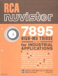
<strong>RCA</strong>-<strong>7587</strong><br />
SHARP-CUTOFF TETRODE<br />
<strong>Nuvistor</strong> Type for Industrial Applications<br />
nCA-<strong>7587</strong> IS a sharp-cutoff, general-purpose tetrode of the<br />
nuvistor type. It is designed for use in a wide variety of<br />
industrial and military small-signal applications requiring compact~<br />
ness, low current drain, relatively low-voltage operation, exceptional<br />
uniformity of characteristics from tube to tube, and ability to<br />
withstand severe mechanical shock and vibration.<br />
These features plus its small size and light weight make<br />
Ac too. L the <strong>7587</strong> particularly suitable for rf-if, video-amplifier, and<br />
Size . .<br />
mIxer serVIce.<br />
•<br />
General Features<br />
The <strong>7587</strong> has an all-metal-and-ceramic envelope provided with two peripheral<br />
lugs of unequal width to facilitate insertion id a socket. It is only 1. 65"<br />
long, less than 1/2" in diameter, and weighs approximately 2.35 g. The <strong>7587</strong><br />
features (1) avery rugged structure of unique design (2) a6.3-volt low-wattage<br />
heater, and a specially designed cathode to assure very low heater-cathode<br />
leakage, (3) high transconductance at low plate current (10600 micromhos at 10<br />
milliamperes), (4) very high input impedance, (5) high perveance, and (6)<br />
ability to operate at full ratings at any altitude.<br />
Structural Features<br />
A major feature of the <strong>7587</strong> is its all-ceramic-and-metal construction<br />
utilizing a light-weight, cantilever-supported cylindrical electrode structure.<br />
This unique type of electrode structure, inherent in the nuvistor design,<br />
provides a structure of excellent mechanical stability and extreme ruggedness.<br />
All connections are brazed at very high temperatures in a hydrogen atmosphere<br />
to eliminate the structural strain and element distortion often caused by<br />
welding. The tube is also exhausted and sealed at very high temperatures to<br />
eliminate the gases and impurities which are generally present in electron<br />
devices processed at low temperatures.<br />
The structure of the <strong>7587</strong> nuvistor tetrode also permits automatic assembly<br />
using parts made to extremely small tolerances, thus assuring exceptional<br />
uniformity of characteristics from tube to tube.<br />
•<br />
Special Tests and Controls<br />
The <strong>7587</strong> is rigidly controlled during manufacture, and is subjected to<br />
rigorous tests for intermittent shorts; for early-hour, lOO-hour, and lOOO-hour<br />
life performance; for resistance to impact shock, low-frequency vibration,<br />
variable-frequency vibration, low-pressure breakdown, and heater cycling.<br />
© 1961 by Radio Corporotion of America<br />
All Rights Reserved - 2 - 6-61
<strong>7587</strong><br />
Special Tests and Controls (Cont'd)<br />
These special controls and tests, together with high transconductance at<br />
low plate current and voltage, small power requirements, ability to operate<br />
at full ratings at any altitude, and extremely small size, make the <strong>7587</strong> nuvistor<br />
tetrode exceptionally desirable for critical industrial applications - for<br />
example, in communications equipment, control and instrumentation equipment,<br />
medical electronic equipment, TV cameras, and test and measurement instruments,<br />
Electrical:<br />
GENERAL DATA<br />
Heater, for Unipotential Cathode:<br />
•<br />
•<br />
Voltage (ac or dc) . 6.3 ± 10% volts<br />
Current at 6.3 volts . O. 15 ampere<br />
Direct Interelectrode Capacitances:<br />
Grid-No.l to plate . 0.012 max. J1.J1.f<br />
Grid-No.l to cathode, grid-No.2, heater & shell 7.0 J1.J1.f<br />
Plate to cathode, grid-No.2, heater & shell 1.4 J1.J1. f<br />
Heater to cathode . 1.4 J1.J1.f<br />
Characteristics, Class AI<br />
Ampl ifier:<br />
Plate-Supply Voltage.. 125 volts<br />
Grid-No.2 Supply Voltage. 50 volts<br />
Cathode Resistor..... 68 ohms<br />
Plate Resistance (Approx.). 0.2 megohm<br />
Transconductance. 10600 J1.mhos<br />
Pll1te Current .. 10 ma<br />
Grid-No.2 Current 2.7 ma<br />
Grid-No.l Voltage (Approx.) for plate current of 10 J1.a. 4.5 volts<br />
Mechan i ca I:<br />
Operating Position.<br />
.. Any<br />
Maximum Overall Length. 1. 050"<br />
Maximum Seated Length 0.840"<br />
Maximum Diameter. 0.440"<br />
Envelope.<br />
Cap ..<br />
Base..<br />
Socket.<br />
.Metal and Ceramic Shell<br />
. . . . . JEDEC No.Cl-44<br />
.Medium Ceramic-Wafer Twelvar 5-Pin (JEDEC No.E5-65)<br />
. Cinch Mfg. Co. No.133 65 10 001, or Equivalent<br />
INDUSTRIAL SERVICE<br />
Maximum Ratings, Absolute-Maximum Values:<br />
For Operation at Any Altitude<br />
PLATE SUPPLY VOLTAGE. . . . . . . . 330 max. volts<br />
PLATE VOLTAGE . . . . . . . . 250 max. volts<br />
GRID-No.2 (SCREEN-GRID) SUPPLY VOLTAGE. 330 max. volts<br />
GRID-No.2 VOLTAGE . 110 max. volts<br />
GRID-No.l (CONTROL-GRID) VOLTAGE:<br />
Negative bias value 55 max. volts<br />
Peak positive value 2 max. volts<br />
CATHODE CURRENT . 20 max. rna<br />
GRID-No. 1 CURRENT. 2 max. rna<br />
- 3
<strong>7587</strong><br />
PLATE DISSIPATION . . . . . . 2.2 max. watts<br />
GRID-No.2 INPUT . 0.2 max. watt<br />
PEAK HEATER-CATHODE VOLTAGE:<br />
Heater negative with respect to cathode 100 max. volts<br />
Heater positive with respect to cathode 100 max. val ts<br />
Maximum Circuit Values:<br />
Grid-No.l Circuit Resistance: a<br />
For fixed-bias operation.. 0.5 max. megohm<br />
For cathode-bias operation. I max. megohm<br />
a For Operation at Metal-Shell Temperatures up to 150 0<br />
Page 9).<br />
C (See Dimensional Outline Drawing on<br />
CHARACTER I ST I CS RANGE VALUES FOR EQU I PMENT DES I GN<br />
Note Min. Max.<br />
Heater Current. 1 0.140 0.160 ampere<br />
Direct Interelectrode Capacitances:<br />
Grid-No.l to plate. 2 0.012<br />
Grid-No.l to cathode, grid No.2, heater & shell 2 6.0 8.0<br />
Plate to cathode, grid No.2, heater & shell 2 1.2 1.6<br />
Heater to cathode 2 1.1 1.7<br />
Plate Current (1) 1,3 8.5 11. 5<br />
Plate Current (2) 1,4 50 !-'a<br />
Grid-No.2 Current 1,3 1.8 3.6 ma<br />
Transconductance (1). 1,3 9000 12200 !-,mhos<br />
Transconductance (2). 3,5 8000 !-,mhos<br />
Transconductance Change:<br />
Difference between Transconcluctance<br />
(1) and Transconductance (2), expressed<br />
In per cent of Transconductance (1) 20 %<br />
Reverse Grid Current. 1,6 0.1 !-'a<br />
Heater-Cathode Leakage Current:<br />
Heater negative with respect to cathode 1,8 5.0 !-'a<br />
Heater positive with respect to cathode 1,8 5.0 !-'a<br />
Leakage Resistance:<br />
Between grid No.2 and all other electrodes<br />
tied together 1,7 500 megohms<br />
Between grid No. 1 and all other electrodes<br />
tied together 1,9 500 megohms<br />
Between plate and all other electrodes<br />
tied together 1, 10 500 megohms<br />
• •<br />
•<br />
• 1<br />
Note 1: With 6.3 volts ac or dc on heater.<br />
Note 2: Measured in accordance with EIA Standard RS-19l-A.<br />
Note 3: With dc plate volts = 125, dc grid-No.2 volts = 50, cathode resistor<br />
= 68 ohms, and cathode-bypass capacitor = 1000 !-,f.<br />
Note 4: With dc plate volts = 125, dc grid-No.2 volts = 50, dc grid-No. 1<br />
volts = -6, and metal shell grounded.<br />
Note 5: With 5.7 volts ac or dc on heater.<br />
Note 6: With dc plate volts = 200, de grid-No.2 volts = 70, grid-No.l supply<br />
volts= -1.6, grid-No. 1 resistor= 0.5 megohm, and metal shell grounded.<br />
- 4 -
<strong>7587</strong><br />
Note 7: With grid-No.2 100 volts negative with respect to all other electrodes<br />
tied together.<br />
Note 8: With 100 volts dc applied between heater and cathode.<br />
Note 9: With grid No. 1 100 volts negative with respect to all other electrodes<br />
tied together.<br />
Note 10:<br />
Shock Rating:<br />
With plate 300 volts negative with respect to all other electrodes<br />
tied together.<br />
SPECIAL RATINGS AND<br />
PERFORMANCE DATA<br />
Impact Acceleration. 1000 max. g<br />
This test is performed on a sample lot of tubes from each production run<br />
to determine ability of tube to withstand the specified impact acceleration.<br />
•<br />
Tubes are held rigid in four different positions in a Navy Type, High-impact<br />
(flyweight) Shock Machine and are subjected to 20 blows at the specified maximum<br />
impact acceleration. At the end of this test, tubes are criticized for change<br />
in transconductance, reverse grid current, and heater-cathode leakage current,<br />
and are then subjected to the Variable-Frequency Vibration Test described later.<br />
Fatigue Rating:<br />
Vibrational Acceleration. 2.5 max. g<br />
This test is performed on a sample lot of tubes to determine ability of<br />
tube to withstand the specified vibrational acceleration. Tubes are rigidly<br />
mounted, supplied with rated heater voltage only, and subjected for 48 hours<br />
to 2.5 g vibrational acceleration at 60 cycles per second in a direction<br />
perpendicular to the longitudinal axis of the tube. At the end of this test,<br />
tubes are criticized for the same characteristics and end-point values as in<br />
the Shock Rating Test described previously.<br />
Variable-Frequency-Vibration Performance:<br />
This test is performed on a sample lot of tubes from each production run.<br />
The tube is operated under the conditions specified in CHARACTERISTICS RANGE<br />
VALUES for Transconductance (1) with the addition of a plate-load resistor of<br />
2000 ohms. During operation, tube is vibrated in a direction perpendicular to<br />
the longitudinal axis of the tube through the frequency range from 50 to 15000<br />
cycles per second with a constant vibrational acceleration of I g. During the<br />
test, tube must not show an rms output voltage across the plate-load resistor<br />
in excess of:<br />
35 millivolts over the frequency range from 50 to 6000 cps<br />
500 millivolts over the frequency range from 6000 to 15000 cps<br />
Low-Pressure Voltage-Breakdown Test:<br />
This test is performed on a sample lot of tubes from each production run.<br />
In this test tubes are operated with 240 rms volts applied between plate and<br />
all other electrodes and will not break down or show evidence of corona when<br />
subjected to air pressures equivalent to altitudes up to 100000 feet.<br />
Heater Cycl ing:<br />
Cycles of Intermittent Operation.<br />
2000 min. cycles<br />
This test is performed on a sample lot of tubes from each production run<br />
under the following conditions: heater volts == 7.5, cycled one minute on and<br />
two minutes off; heater 100 volts negative with respect to cathode; grid No. 1,<br />
- 5
<strong>7587</strong><br />
grid No.2, plate, and metal shell connected to ground. At the end of this test<br />
tubes are tested for open heaters and heater-cathode shorts.<br />
Intermittent Shorts:<br />
This test is performed on a sample lot of tubes from each production run.<br />
Tubes are subjected to tIle Thyratron-Type Shorts Test described in MIL-E-ID,<br />
Amendment 2, Par. 4.7.7 J except that tapping is done by hand with a soft rubber<br />
tapper b . The Acceptance Curve for this test is shown in Fig.3. In this test<br />
tubes are criticized for permanent or temporary shorts and open circuits.<br />
Early-Hour Stability Life Performance:<br />
This test is performed on a sample lot of tubes from each production run to<br />
insure that tubes are properly stabilized. In this test tubes are operated<br />
for 20 hours at maximum rated plate dissipation. After two hours o~ operation<br />
and again after 20 hours of operation tubes are checked for transconductance<br />
under the conditions specified in CHARACTERISTICS RANGE VALUES for Transconductance<br />
(1). A tube is rejected if its transconductance after two or 20hours of<br />
operation has changed more than 10 per cent from the O-hour value.<br />
lOO-Hour Life Performance:<br />
This test is performed on a sample lot of tubes from each production run<br />
to insure a low percentage of early-hour inoperatives. Tubes are operated for<br />
lOO llours at maximum rated plate dissipation, and then subjected to the<br />
Intermittent Shorts Test previously described. Tubes must then show a transconductance<br />
of not less than 7600 micromhos under the conditions specified in<br />
CHARACTERISTICS RANGE VALl:ES for Transconductance (1), and a value not greater<br />
than one microampere for reverse grid current.<br />
t<br />
• \<br />
IOOO-Hour Life Performance:<br />
This test is performed on a sample lot of tubes from each production run<br />
to insure high quality of the individual tube and guard against epidemic<br />
failures due to excessive changes in any of the characteristics indicated below.<br />
In this test tubes are operated for 1000 hours at maximum rated plate dissipation<br />
and then criticized for inoperatives, reverse grid current, heater-cathode<br />
leakage current, and the leakage resistance. In addition, the average change<br />
in transconductance of the lot from the O-hour value for Transconductance (1)<br />
specified in CHARACTERISTICS RANGE VALUES, must not exceed 20 per cent at 500<br />
hours and 25 per cent at 1000 hours.<br />
4t<br />
b Specifications for this tapper will be supplied on request.<br />
OPERATING CONSIDERATIONS<br />
The base-pins of the <strong>7587</strong> fit the Cinch Mfg. Co. socket No. 133 65 10 001<br />
or equivalent. The socket may be mounted to hold the tube 1n any position.<br />
The maximum ratings in the tabulated data are established in accordance<br />
with the following definition of the Absolute-Maximum Rating System for rating<br />
electron devices.<br />
Absolute-Maximum ratings are limiting values of operating and environmental<br />
conditions applicable to any electron device of a specified type as defined by<br />
its publ ished data, and should not be exceeded under the worst probable conditions.<br />
- 6
<strong>7587</strong><br />
The device manufacturer chooses these values to provide acceptable serviceability<br />
of the device, taking no responsibility for equipment variations,<br />
envirOllment variations, and the effects of changes in operating conditions due<br />
to variations in device characteristics.<br />
The equipment manufacturer should design so that initially and throughout<br />
life no absolute-maximum value for the intended service is exceeded with<br />
any dpvice under the worst probable operating conchtions with respect to supplyvoltage<br />
variation, equipment component variation, equipment control adjustment,<br />
load variation, signal variation, environmpntal conditions, and variatiuns in<br />
device characteristics .<br />
•<br />
•<br />
Information furnished by ReA is believed to be accurate<br />
and reliable. However, no responsibility is assumed by<br />
ReA for its use; nOT for any infringements of patents<br />
or other rights of third parties which may result from<br />
its use. No license is granted by implication or<br />
otherwise under any patent or patent rights of ReA.<br />
- 7
<strong>7587</strong><br />
Ef·5.3 VOLTS<br />
Ef'''6.3 VOLTS<br />
GRID NlIl VOLTS-50 PLATE VQLTS=J25<br />
GRID NIZ VOLTS'SO<br />
16000<br />
14000<br />
'l'<br />
ol. 0<br />
IN 0 12000<br />
~<br />
0<br />
~~ 2.<br />
N<br />
IOO~<br />
U<br />
H ,<br />
..<br />
i:i ,<br />
0<br />
E<br />
I 0<br />
!!'<br />
..<br />
~<br />
:t 0,<br />
l'<br />
0<br />
~ ".I<br />
.. ~<br />
Z<br />
N. 0 '"<br />
0 I<br />
~<br />
l u<br />
~<br />
u 0 0 ~<br />
20 8000~<br />
'"<br />
N ~<br />
~<br />
~<br />
~<br />
U ~ ~<br />
~<br />
0 ~<br />
0<br />
.''' ~ u<br />
~<br />
.... ><br />
z<br />
0<br />
~ u<br />
~<br />
6000 ::<br />
~ N ,.<br />
><br />
3 t:!<br />
~<br />
z<br />
~<br />
, z<br />
9<br />
0<br />
.. 0<br />
~<br />
w<br />
~<br />
~<br />
3~<br />
0 le<br />
~<br />
~i<br />
il"<br />
)(~<br />
i<br />
.. ....<br />
~<br />
H<br />
0 ~<br />
0 ~ 0<br />
N PLATE lIb) OA GRIO-N'-Z (Iezl MILLIAMPERES<br />
"!<br />
T<br />
i2CM-IOi26<br />
, ,,'"<br />
0..<br />
~<br />
0 10 4000<br />
0<br />
t:!<br />
">,,..<br />
~ 2000<br />
~ •<br />
-4 -3 -2 -, 0<br />
GRID-Nil VOLTS<br />
92.CM-I092.7<br />
•<br />
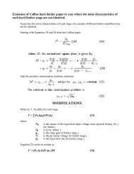
Fig.! • Ave rage Characteristics for Fig.2 - Average Characteristics for<br />
Type <strong>7587</strong>. Type <strong>7587</strong>.<br />
IOOO~<br />
~ ,<br />
,<br />
~<br />
lil • ,<br />
~<br />
~ 1000<br />
U<br />
•<br />
i ,<br />
I ,<br />
~<br />
'" 0<br />
x<br />
~<br />
0 " '00<br />
~<br />
•,<br />
~ ,<br />
~<br />
0<br />
•<br />
•<br />
,<br />
•<br />
./<br />
AREA OF ACCEPTABILITY<br />
I IIII<br />
.<br />
III I I 1 1111<br />
• • • , , , , ,.<br />
10 100 1000<br />
RESISTANCE OF' SHORT-OHMS 111000<br />
92.CS-I04"5<br />
~<br />
~<br />
~<br />
•<br />
Fig.3 - Thyratron-Type Shorts Test for<br />
Type 75.87.<br />
- 8
DIMENSIONAL OUTLINE <strong>7587</strong><br />
METAL CAP ~ f<br />
JEDEC - I "<br />
No.CI-44 .175 .220"t..1IN.<br />
MIN. I<br />
,-1----l=r=~-----.:*<br />
1.050"<br />
MAX.<br />
.840"<br />
MAX.<br />
t.AETAL<br />
SHELL<br />
CERAMIC<br />
CYLINDER<br />
BASE<br />
JEDEC N~ E5-b5<br />
•<br />
.100" MIN.<br />
.130"MAX•<br />
f<br />
.190"<br />
+.020"<br />
-.015"<br />
5 PINS<br />
.Olb" ±.ool" OIA.<br />
~<br />
LARGE<br />
LUG<br />
.'<br />
~8 .'/<br />
0<br />
..,<br />
12<br />
0'0<br />
••<br />
/'<br />
CERAMIC<br />
/,WArER<br />
SMALL<br />
LUG<br />
•<br />
• =PIN CUT OFF<br />
92CS-I0852<br />
NOTE I: MAXIMUM O.D. OF 0.440" IS PERMITTED<br />
ALa'lG O. 190" LUG LENGlll.<br />
NOTE 2: SHELL TEMPERATURE SHOUlll BE MEASURED<br />
IN Za'lE "A" BETWEEN BROKEN LINES.<br />
BASING DIAGRAM (Bottom View)<br />
PIN 1 , A<br />
PIN 7, A<br />
PIN 2, GRID No. 2<br />
PIN S, CATIfODE<br />
PIN 3, A<br />
PIN 9, A<br />
PIN 4, GRID No.1<br />
PIN 10, HEATER<br />
PIN 5, A<br />
PIN IL OMITTED<br />
PIN 6, A<br />
PIN 12, HEATER<br />
CAP, PLATE<br />
J 2AS<br />
A Pin has internal connection and is cut<br />
off close to ceramic wafer--Do Not Use.
<strong>7587</strong><br />
MEDIUM CERAMIC-WAFER TWELVAR BASE<br />
SOCKET INSEFlTION<br />
PLANE<br />
I<br />
,040"'MAX.<br />
INDEX GUIDE<br />
LARGE LUG<br />
I<br />
.'90"!:8fsO"<br />
.I00"MIN•<br />
.IJO"MAX.<br />
METAL SHELL<br />
~ ;:::-T BASE SEATING<br />
r--i1---.400" MIN. I. 0'-:1<br />
.Ol?_"" ~.43~" MAX. 0.0.<br />
x··:
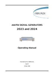
<strong>7587</strong><br />
--PLATE<br />
GRID No.2<br />
"";"-+--HEATER<br />
lICERAMIC<br />
INSULATOR<br />
I<br />
----~~~-CATHODE<br />
~~--.H---GRID No. I<br />
CERAMIC BASE<br />
WAFER<br />
r<br />
INDEXING LUGS<br />
Fig.4 -Illustration of a nuvistor tetr-ode showing cylindrical electrodes<br />
and tripod-like supports.<br />
- 11
![[6]](https://img.yumpu.com/23901941/1/184x260/6.jpg?quality=85)