Assembling Serener GW-01, D945GCLF2 - CarTFT.com
Assembling Serener GW-01, D945GCLF2 - CarTFT.com
Assembling Serener GW-01, D945GCLF2 - CarTFT.com

You also want an ePaper? Increase the reach of your titles
YUMPU automatically turns print PDFs into web optimized ePapers that Google loves.
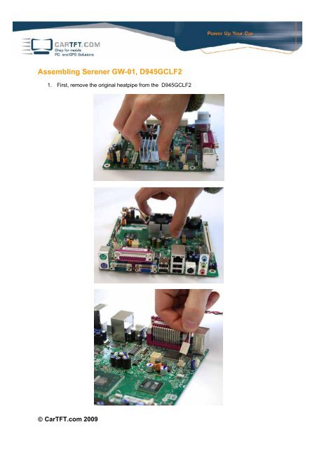
<strong>Assembling</strong> <strong>Serener</strong> <strong>GW</strong>-<strong>01</strong>, <strong>D945GCLF2</strong><br />
1. First, remove the original heatpipe from the <strong>D945GCLF2</strong><br />
© <strong>CarTFT</strong>.<strong>com</strong> 2009
2. Then clean the graphic chip set and the CPU<br />
3. Apply the provided thermal conductance paste in a thin layer on the graphic chip set and the<br />
CPU.<br />
© <strong>CarTFT</strong>.<strong>com</strong> 2009
4. Remove the protective foil from the bottom of the heatpipe and place it carefully on the<br />
graphic chip set as well as the CPU. To fasten it, put a bit of pressure on the top of the<br />
heatpipe and push down the detent clip with needle-nosed pliers. Best if you begin with the<br />
outer three fasteners. The inner clip is preferably to be fastened last.<br />
5. Now, remove the protective foil on the top of the heatpipe.<br />
© <strong>CarTFT</strong>.<strong>com</strong> 2009
6. Place the RAM in the socket<br />
7. Next, place the mainboard as shown in the picture, on the designated spot in the case and<br />
screw it in place with the provided screws.<br />
© <strong>CarTFT</strong>.<strong>com</strong> 2009
8. The system is now prepared for the internal connection of the cables.<br />
9. Please begin with laying of the VGA connection<br />
© <strong>CarTFT</strong>.<strong>com</strong> 2009
Plug the VGA plug which is attached to the case in the designated VGA port at the slot panel.<br />
10. Now connect the Ethernet connector of the case with the network connector on the slot panel.<br />
© <strong>CarTFT</strong>.<strong>com</strong> 2009
11. Continue with the wiring of the COM interface.<br />
The COM cable of the case will be connected, as well as the cables of the VGA and Ethernet<br />
connector before, to the slot panel of the mainboard.<br />
© <strong>CarTFT</strong>.<strong>com</strong> 2009
12. Next Step is to connect the P4 cable of the power supply with the mainboard.<br />
13. Now, the 20pol ATX connector from the power supply also has to be connected with the<br />
mainboard. Place the ATX connector all the way to the right hand side of the mainboard ATX<br />
connector. On the left hand side there will be 4 pins left open, these 4 pins are not necessary<br />
for the function of the mainboard.<br />
© <strong>CarTFT</strong>.<strong>com</strong> 2009
14. Connect the USB cable which is attached to the case with the interface of the mainboard.<br />
© <strong>CarTFT</strong>.<strong>com</strong> 2009
15. Next, you will have to change the power switch cable on the power supply from J9 to J8.<br />
In the following Stepp, connect the cable with the power switch connector on the mainboard.<br />
© <strong>CarTFT</strong>.<strong>com</strong> 2009
16. Connect the SATA data transfer cable with the SATA connector on the mainboard<br />
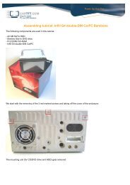
17. For the next Step, take the lid of the case. Mount the buffer to the edges of the HDD/SSD<br />
mounting.<br />
© <strong>CarTFT</strong>.<strong>com</strong> 2009
Place the designated HDD or SSD on the mounting and screw it on the mounting.<br />
18. Connect the SATA power – and data transfer cable from the mainboard and power supply with<br />
the HDD/SSD.<br />
© <strong>CarTFT</strong>.<strong>com</strong> 2009
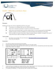
19. For now, leave the lid of the case next to the case and start working on the jumper settings of<br />
the power supply. For this, connect the power cable via plus, minus and ignition. The status<br />
LED, which is on a cable <strong>com</strong>ing from the power supply, will indicate if the system starts<br />
running.<br />
The jumper settings will be conducted using the button on the power supply (marked with SW1 on<br />
the picture). The three LEDs next to it indicate the jumper settings. Press the button until the<br />
desired LED <strong>com</strong>bination (see below) is displayed.<br />
Now, disconnect the ignition cable from the power source. The power supply now has to shut<br />
down in one of the vehicle modes. After connecting the power source with the ignition cable again<br />
the PC will boot. As soon as you have set the desired mode you may continue with the<br />
assembling of the system.<br />
© <strong>CarTFT</strong>.<strong>com</strong> 2009
20. Distribute the unused cables in the case.<br />
Apply the thermal conductance paste on the top of the heatpipe in a very thin layer.<br />
© <strong>CarTFT</strong>.<strong>com</strong> 2009
21. Now, place the lid on the case and screw it on with the 6 case screws provided.<br />
Pay attention that no cable slipped between the case and the lid.<br />
22. Configuration of the system is now finished and it can be connected and installed in the<br />
vehicle. When you place the system in front of you, on the left screw connector the USB and<br />
COM interfaces are ac<strong>com</strong>modated.<br />
The second connector from the left is the Ethernet port.<br />
© <strong>CarTFT</strong>.<strong>com</strong> 2009
The third connector from the left is designated for VGA.<br />
On the right side are the connectors fort he power supply - utilizing plus, minus and ignition.<br />
If you find yourself overwhelmed with this assembly, feel free to contact us and we can assemble<br />
the system for you for a little surcharge.<br />
© <strong>CarTFT</strong>.<strong>com</strong> 2009