RS232 serial cable pinout i...
RS232 serial cable pinout i...
RS232 serial cable pinout i...

You also want an ePaper? Increase the reach of your titles
YUMPU automatically turns print PDFs into web optimized ePapers that Google loves.
<strong>RS232</strong> <strong>serial</strong> <strong>cable</strong> <strong>pinout</strong> information<br />
http://www.lammertbies.nl/comm/<strong>cable</strong>/RS-232.html<br />
1 of 4 06/10/2009 13:42<br />
<strong>RS232</strong> <strong>serial</strong> <strong>cable</strong>s <strong>pinout</strong><br />
On these pages<br />
<strong>RS232</strong> <strong>serial</strong> connector pin assignment<br />
<strong>RS232</strong> DB9 to DB25 converter<br />
<strong>RS232</strong> <strong>serial</strong> loopback test plugs<br />
<strong>RS232</strong> null modem <strong>cable</strong>s<br />
Spy / monitor <strong>cable</strong><br />
Serial printer <strong>cable</strong>s<br />
Yost <strong>RS232</strong> on RJ45 standard<br />
<strong>RS232</strong> support forum New<br />
<strong>RS232</strong> <strong>serial</strong> <strong>cable</strong> layout<br />
Almost nothing in computer interfacing is more confusing than selecting the right <strong>RS232</strong> <strong>serial</strong> <strong>cable</strong>. These pages are intended to<br />
provide information about the most common <strong>serial</strong> <strong>RS232</strong> <strong>cable</strong>s in normal computer use, or in more common language "How do<br />
I connect devices and computers using <strong>RS232</strong>?"<br />
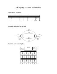
<strong>RS232</strong> <strong>serial</strong> connector pin assignment<br />
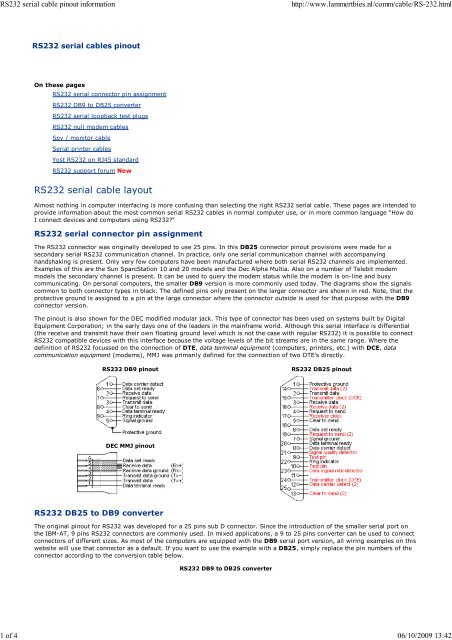
The <strong>RS232</strong> connector was originally developed to use 25 pins. In this DB25 connector <strong>pinout</strong> provisions were made for a<br />
secondary <strong>serial</strong> <strong>RS232</strong> communication channel. In practice, only one <strong>serial</strong> communication channel with accompanying<br />
handshaking is present. Only very few computers have been manufactured where both <strong>serial</strong> <strong>RS232</strong> channels are implemented.<br />
Examples of this are the Sun SparcStation 10 and 20 models and the Dec Alpha Multia. Also on a number of Telebit modem<br />
models the secondary channel is present. It can be used to query the modem status while the modem is on-line and busy<br />
communicating. On personal computers, the smaller DB9 version is more commonly used today. The diagrams show the signals<br />
common to both connector types in black. The defined pins only present on the larger connector are shown in red. Note, that the<br />
protective ground is assigned to a pin at the large connector where the connector outside is used for that purpose with the DB9<br />
connector version.<br />
The <strong>pinout</strong> is also shown for the DEC modified modular jack. This type of connector has been used on systems built by Digital<br />
Equipment Corporation; in the early days one of the leaders in the mainframe world. Although this <strong>serial</strong> interface is differential<br />
(the receive and transmit have their own floating ground level which is not the case with regular <strong>RS232</strong>) it is possible to connect<br />
<strong>RS232</strong> compatible devices with this interface because the voltage levels of the bit streams are in the same range. Where the<br />
definition of <strong>RS232</strong> focussed on the connection of DTE, data terminal equipment (computers, printers, etc.) with DCE, data<br />
communication equipment (modems), MMJ was primarily defined for the connection of two DTE's directly.<br />
<strong>RS232</strong> DB9 <strong>pinout</strong><br />
<strong>RS232</strong> DB25 <strong>pinout</strong><br />
DEC MMJ <strong>pinout</strong><br />
<strong>RS232</strong> DB25 to DB9 converter<br />
The original <strong>pinout</strong> for <strong>RS232</strong> was developed for a 25 pins sub D connector. Since the introduction of the smaller <strong>serial</strong> port on<br />
the IBM-AT, 9 pins <strong>RS232</strong> connectors are commonly used. In mixed applications, a 9 to 25 pins converter can be used to connect<br />
connectors of different sizes. As most of the computers are equipped with the DB9 <strong>serial</strong> port version, all wiring examples on this<br />
website will use that connector as a default. If you want to use the example with a DB25, simply replace the pin numbers of the<br />
connector according to the conversion table below.<br />
<strong>RS232</strong> DB9 to DB25 converter
<strong>RS232</strong> <strong>serial</strong> <strong>cable</strong> <strong>pinout</strong> information<br />
http://www.lammertbies.nl/comm/<strong>cable</strong>/RS-232.html<br />
2 of 4 06/10/2009 13:42<br />
<strong>RS232</strong> <strong>serial</strong> loopback test plugs<br />
DB9 - DB25 conversion<br />
DB9 DB25 Function<br />
1 8 Data carrier detect<br />
2 3 Receive data<br />
3 2 Transmit data<br />
4 20 Data terminal ready<br />
5 7 Signal ground<br />
6 6 Data set ready<br />
7 4 Request to send<br />
8 5 Clear to send<br />
9 22 Ring indicator<br />
The following <strong>RS232</strong> connectors can be used to test a <strong>serial</strong> port on your computer. The data and handshake lines have been<br />
linked. In this way all data will be sent back immediately. The PC controls its own handshaking. The first test plug can be used to<br />
check the function of the <strong>RS232</strong> <strong>serial</strong> port with standard terminal software. The second version can be used to test the full<br />
functionality of the <strong>RS232</strong> <strong>serial</strong> port with Norton Diagnostics or CheckIt.<br />
<strong>RS232</strong> loopback test plug for terminal emulation software<br />
DB9 DB25 Function<br />
1 + 4 + 6 6 + 8 + 20 DTR CD + DSR<br />
2 + 3 2 + 3 Tx Rx<br />
7 + 8 4 + 5 RTS CTS
<strong>RS232</strong> <strong>serial</strong> <strong>cable</strong> <strong>pinout</strong> information<br />
http://www.lammertbies.nl/comm/<strong>cable</strong>/RS-232.html<br />
3 of 4 06/10/2009 13:42<br />
<strong>RS232</strong> loopback test plug for Norton Diagnostics and CheckIt<br />
DB9 DB25 Function<br />
1 + 4 + 6 + 9 6 + 8 + 20 + 22 DTR CD + DSR + RI<br />
2 + 3 2 + 3 Tx Rx<br />
7 + 8 4 + 5 RTS CTS<br />
Testing occurs in a few steps. Data is sent on the Tx line and the received information on the Rx input is then compared with the<br />
original data. The signal level on the DTR and RTS lines is also controlled by the test software and the attached inputs are read<br />
back in the software to see if these signal levels are properly returned. The second <strong>RS232</strong> test plug has the advantage that the<br />
ring-indicator RI input line can also be tested. This input is used by modems to signal an incoming call to the attached computer.<br />
<strong>RS232</strong> null modem <strong>cable</strong>s<br />
The easiest way to connect two PC's is using an <strong>RS232</strong> null modem <strong>cable</strong>. The only problem is the large variety of <strong>RS232</strong> null<br />
modem <strong>cable</strong>s available. For simple connections, a three line <strong>RS232</strong> <strong>cable</strong> connecting the signal ground and receive and transmit<br />
lines is sufficient. Depending of the software used, some sort of handshaking may however be necessary. Use the <strong>RS232</strong> null<br />
modem selection table to find the right null modem <strong>cable</strong> for each purpose. For a Windows 95/98/ME Direct Cable Connection,<br />
the <strong>RS232</strong> null modem <strong>cable</strong> with loop back handshaking is a good choice.<br />
<strong>RS232</strong> null modem <strong>cable</strong>s with handshaking can be defined in numerous ways, with loopback handshaking to each PC, or<br />
complete handshaking between the two systems. The most common null modem <strong>cable</strong> types are shown here.<br />
Simple <strong>RS232</strong> null modem without handshaking (Null modem explanation)<br />
Connector 1 Connector 2 Function<br />
2 3 Rx Tx<br />
3 2 Tx Rx<br />
5 5 Signal ground<br />
<strong>RS232</strong> null modem with loop back handshaking (Null modem explanation)<br />
Connector 1 Connector 2 Function<br />
2 3 Rx Tx<br />
3 2 Tx Rx<br />
5 5 Signal ground<br />
1 + 4 + 6 - DTR CD + DSR<br />
- 1 + 4 + 6 DTR CD + DSR<br />
7 + 8 - RTS CTS
<strong>RS232</strong> <strong>serial</strong> <strong>cable</strong> <strong>pinout</strong> information<br />
http://www.lammertbies.nl/comm/<strong>cable</strong>/RS-232.html<br />
4 of 4 06/10/2009 13:42<br />
- 7 + 8 RTS CTS<br />
<strong>RS232</strong> null modem with partial handshaking (Null modem explanation)<br />
Connector 1 Connector 2 Function<br />
1 7 + 8 RTS 2 CTS 2 + CD 1<br />
2 3 Rx Tx<br />
3 2 Tx Rx<br />
4 6 DTR DSR<br />
5 5 Signal ground<br />
6 4 DSR DTR<br />
7 + 8 1 RTS 1 CTS 1 + CD 2<br />
<strong>RS232</strong> null modem with full handshaking (Null modem explanation)<br />
Connector 1 Connector 2 Function<br />
2 3 Rx Tx<br />
3 2 Tx Rx<br />
4 6 DTR DSR<br />
5 5 Signal ground<br />
6 4 DSR DTR<br />
7 8 RTS CTS<br />
8 7 CTS RTS<br />
Apr. 2008 | Site map | Contact | Privacy policy Copyright © 1997-2009 Lammert Bies, All rights reserved