
Create successful ePaper yourself
Turn your PDF publications into a flip-book with our unique Google optimized e-Paper software.
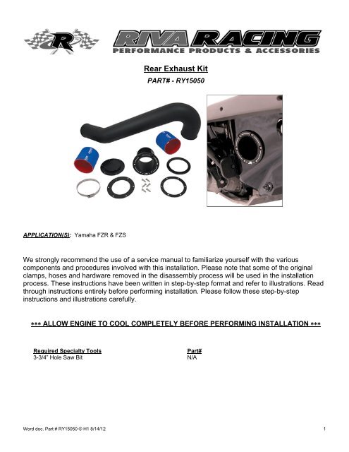
<strong>Rear</strong> <strong>Exhaust</strong> <strong>Kit</strong><br />
PART# - RY15050<br />
APPLICATION(S): Yamaha FZR & FZS<br />
We strongly recommend the use of a service manual to familiarize yourself with the various<br />
components and procedures involved with this installation. Please note that some of the original<br />
clamps, hoses and hardware removed in the disassembly process will be used in the installation<br />
process. These instructions have been written in step-by-step format and refer to illustrations. Read<br />
through instructions entirely before performing installation. Please follow these step-by-step<br />
instructions and illustrations carefully.<br />
ALLOW ENGINE TO COOL COMPLETELY BEFORE PERFORMING INSTALLATION <br />
Required Specialty Tools<br />
Part#<br />
3-3/4” Hole Saw Bit N/A<br />
Word doc. Part # RY15050 © H1 8/14/12 1
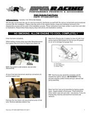
- INSTALLATION INSTRUCTIONS -<br />
Allow engine to cool completely.<br />
Remove seats and rear storage bin.<br />
Remove rear grab handle/seat support. Four bolts at<br />
center and three under grab handle.<br />
In jet pump area locate and remove rubber flap at right<br />
side of jet pump unit.<br />
3 bolts &<br />
wahsers<br />
At exhaust outlet remove nuts and washers (6) securing<br />
exhaust outlet to hull.<br />
6 nuts &<br />
wahsers<br />
Inside engine compartment at rear of craft remove and<br />
discard exhaust baffles 1 and hose 2 between water box<br />
and exhaust outlet hose. Save OEM clamps for<br />
installation portion.<br />
1<br />
2<br />
Remove OEM exhaust outlet hose from inside of hull.<br />
Remove aluminum ring with studs from exhaust outlet<br />
hose. Retain ring. Discard exhaust outlet hose and<br />
exhaust outlet valve.<br />
Install supplied billet exhaust outlet block-off onto<br />
aluminum ring so that raised area faces the same<br />
direction as the six threaded studs. Install supplied<br />
rubber gasket over studs and onto billet block-off<br />
(adhesive side first).<br />
1<br />
Gasket<br />
Loosen bolts (4) securing ride plate to hull.<br />
Raised side of<br />
block-off plate.<br />
Word doc. Part # RY15050 © H1 8/14/12 2
Cut out supplied template (last page) and affix to right<br />
rear side of hull below rub rail. Mark center only.<br />
Insert supplied billet exhaust outlet into newly created<br />
opening in transom so that ‘R’ logo is at bottom. Secure<br />
with tape.<br />
Using a 3-3/4” hole saw bit drill opening for supplied<br />
billet exhaust outlet.<br />
Test fit supplied billet exhaust outlet. It may be<br />
necessary to grind or file additional material to enable<br />
outlet to fit. NOTE: Do not remove too much material.<br />
Outlet should just fit into opening.<br />
Thoroughly clean hull inside and out. Install supplied<br />
exhaust outlet block-off from inside and secure evenly<br />
using stock nuts and washers. NOTE: Do not over<br />
tighten nuts.<br />
Drill one bolt hole and insert one supplied M6 button<br />
head bolts. Repeat for remaining bolts.<br />
Remove outlet and thoroughly clean it as well as hull,<br />
both inside and out.<br />
Install supplied rubber gasket onto back of billet exhaust<br />
outlet flange (adhesive side first). Install outlet into hull.<br />
NOTE: Apply blue Loctite to threads on supplied button<br />
head bolts and insert into outlet.<br />
Secure outlet in place with tape<br />
From inside of hull carefully place supplied billet collar<br />
(flat side towards hull) onto exhaust outlet.<br />
Install with<br />
flat side<br />
towards hull.<br />
Slide collar onto outlet until you feel it touch one or both<br />
of top two bolts. Carefully try to center one or both of the<br />
top two bolts in the threads of the collar. From outside of<br />
hull slowly tighten bolt aligned with collar. Once you feel<br />
it grab tighten a few turns. Move to opposite bolt and do<br />
the same. Once two opposing bolts easily screw into<br />
collar install remaining bolts and tighten evenly. NOTE:<br />
Do not over tighten bolts.<br />
Word doc. Part # RY15050 © H1 8/14/12 3
Install one of the supplied exhaust couplers onto billet<br />
exhaust outlet enough to secure coupler to outlet.<br />
Secure using the supplied hose clamp. NOTE: Do not<br />
over tighten clamp. Loosely install one of the<br />
previously removed OEM hose clamps over exhaust<br />
outlet coupler.<br />
Tighten hose clamps (2) securing <strong>Exhaust</strong> Tube in<br />
place. NOTE: Do not over tighten clamps. Tighten<br />
coupler securing exhaust pipe to water box inlet if<br />
loosened.<br />
Replace rubber flap at right side of jet pump. NOTE:<br />
NOTE: Apply blue Loctite to bolts. Do not over<br />
tighten.<br />
Replace ride plate. NOTE: Apply blue Loctite to<br />
bolts. Torque evenly to 17 N•m (12.5 ft•lb).<br />
Replace speedo sensor. NOTE: Apply blue Loctite to<br />
bolts. Torque evenly to 4 N•m (3 ft•lb).<br />
Replace deck beam. NOTE: Apply blue Loctite to<br />
bolts. Do not over tighten.<br />
Thoroughly clean outside of water box outlet using a<br />
non-residual cleaner. Install second supplied exhaust<br />
coupler halfway onto outlet and secure with one of the<br />
previously removed OEM hose clamps. NOTE: Do not<br />
over tighten clamp. Loosely install the last previously<br />
removed OEM hose clamp over exhaust coupler.<br />
Check bilge for tools, rags, etc. Start craft and run using<br />
flush kit to check for exhaust leaks at connecting points<br />
for <strong>Rear</strong> <strong>Exhaust</strong> <strong>Kit</strong>.<br />
Insert straight end of supplied <strong>Exhaust</strong> Tube into rear<br />
exhaust outlet coupler. TIP: Use window cleaner to<br />
ease installation.<br />
Insert curved end of <strong>Exhaust</strong> Tube into coupler on water<br />
box outlet. TIP: Use window cleaner to ease installation.<br />
Word doc. Part # RY15050 © H1 8/14/12 4
Remember, the water belongs to everyone.<br />
Please ride responsibly and respect the environment!<br />
Technical Support<br />
For answers to questions regarding installation or trouble shooting <strong>RIVA</strong> Performance Products contact:<br />
<strong>RIVA</strong> Technical Support directly at (954) 247-0705 or by e-mail at tech_support@rivamotorsports.com<br />
Limited Warranty<br />
<strong>RIVA</strong> <strong>Racing</strong> <strong>Rear</strong> <strong>Exhaust</strong> <strong>Kit</strong>s carry a 90-day limited warranty to the original purchaser. They are warranted to be free of defects in materials and<br />
workmanship under normal use and service. Customer modified components will be void of warranty. This warranty is limited to defects in the primary<br />
components only. Finish and/or wear marks in or on primary components are not covered under this warranty.<br />
<strong>RIVA</strong> <strong>Racing</strong>’s liability is expressly limited to the repair or replacement of the components contained within or associated with this kit. <strong>RIVA</strong> <strong>Racing</strong><br />
agrees to repair or at <strong>RIVA</strong>’s option, replace any defective unit without charge, if product is returned to <strong>RIVA</strong> <strong>Racing</strong> freight prepaid within the warranty<br />
period. Any equipment returned which, in <strong>RIVA</strong>’s opinion, has been subjected to misuse, abuse, overheating or accident shall not be covered by this<br />
warranty.<br />
<strong>RIVA</strong> <strong>Racing</strong> shall have no liability for special, incidental or consequential damages or injury to persons or property from any cause arising from the<br />
sale, installation or use of this product.<br />
No other warranty, express or implied, including, but not limited to the implied warranties of merchantability and fitness for a particular purpose, applies.<br />
Various states do not allow for the limitation of incidental or consequential damages and therefore the above exclusion or limitation may not apply to<br />
you.<br />
Warranty does not include the expenses related to freight or transportation of parts or compensation for any inconvenience or loss of use while being<br />
repaired. A copy of the original invoice must accompany all warranty claims.<br />
Warranted replacement parts will be returned freight collect.<br />
Word doc. Part # RY15050 © H1 8/14/12 5
IMPORTANT:<br />
Before printing make sure that<br />
“Output Option/Printing Type/Scaling”<br />
are set to NONE in the Print Dialog<br />
Properties Window for your printer.<br />
Word doc. Part # RY15050 © H1 8/14/12 6