
Create successful ePaper yourself
Turn your PDF publications into a flip-book with our unique Google optimized e-Paper software.
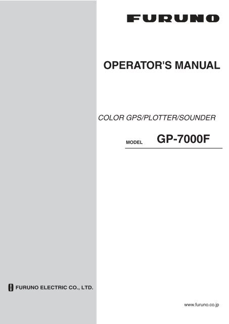
OPERATOR'S MANUAL<br />
COLOR <strong>GP</strong>S/PLOTTER/SOUNDER<br />
MODEL<br />
<strong>GP</strong>-<strong>7000F</strong><br />
www.furuno.co.jp
*00014913712*<br />
*00014913712*
IMPORTANT NOTICES<br />
• This manual is intended for use by native speakers of English.<br />
• No part of this manual may be copied or reproduced without written permission.<br />
• If this manual is lost or worn, contact your dealer about replacement.<br />
• The contents of this manual and equipment specifications are subject to change without notice.<br />
• The example screens (or illustrations) shown in this manual may not match the screens you<br />
see on your display. The screen you see depends on your system configuration and equipment<br />
settings.<br />
• Store this manual in a convenient place for future reference.<br />
• FURUNO will assume no responsibility for the damage caused by improper use or modification<br />
of the equipment (including software) by an unauthorized agent or a third party.<br />
• When it is time to discard this product it must be done according to local regulations for disposal<br />
of industrial waste. For disposal in the USA, refer to the Electronics Industries Alliance<br />
(http://www.eiae.org/).<br />
i
SAFETY INSTRUCTIONS<br />
Do not open the equipment.<br />
Do not disassemble or modify the<br />
equipment.<br />
Fire, electrical shock or serious injury<br />
can result.<br />
Immediately turn off the power at the<br />
switchboard if the equipment is emitting<br />
smoke or fire.<br />
Continued use of the equipment can<br />
cause electrical shock.<br />
Do not operate the equipment with wet<br />
hands.<br />
Electrical shock can result.<br />
Use the proper fuse.<br />
WARNING<br />
Hazardous voltage which can cause<br />
electrical shock, burn or serious injury<br />
exists inside the equipment. Only qualified<br />
personnel should work inside the equipment.<br />
Fuse rating is shown on the power cable.<br />
Use of a wrong fuse can result in damage<br />
to the equipment.<br />
Do not maneuver the vessel based<br />
on the depth indication alone.<br />
Grounding may result.<br />
About the TFT LCD<br />
The TFT LCD is constructed using the<br />
latest LCD techniques, and displays<br />
99.99% of its pixels. The remaining 0.01%<br />
of the pixels may drop out or blink, however<br />
this is not an indication of malfunction.<br />
CAUTION<br />
Do not use the equipment for other than<br />
its intended purpose.<br />
No one navigation device should ever be<br />
solely replied upon for the navigation of<br />
a vessel.<br />
Always confirm position against all available<br />
aids to navigation, for safety of vessel and<br />
crew.<br />
Do not turn on the equipment with the<br />
transducer out of water.<br />
The transducer may be damaged.<br />
Use the proper gain setting.<br />
Incorrect gain may produce wrong depth<br />
indication, possibly result ing in a<br />
dangerous situation. See "Adjusting the<br />
gain" on page 10-11.<br />
The picture is not refreshed when<br />
picture advancement is stopped.<br />
Maneuvering the vessel in this condition<br />
may result in a dangerous situation.<br />
A warning label is attached to the equipment.<br />
Do not remove the label. If the<br />
label is missing or illegible, contact<br />
a FURUNO agent or dealer.<br />
WARNING<br />
To avoid electrical shock, do not<br />
remove cover. No user-serviceable<br />
parts inside.<br />
Name: Warning Label (1)<br />
Type: 86-003-1011-1<br />
Code No.: 100-236-231<br />
ii
FOREWORD<br />
Congratulations on your choice of the FURUNO <strong>GP</strong>-<strong>7000F</strong> COLOR <strong>GP</strong>S/PLOT-<br />
TER/SOUNDER. We are confident you will see why the FURUNO name has<br />
become synonymous with quality and reliability.<br />
For 60 years FURUNO Electric Company has enjoyed an enviable reputation for<br />
innovative and dependable marine electronics equipment. This dedication to<br />
excellence is furthered by our extensive global network of agents and dealers.<br />
This equipment is designed and constructed to meet the rigorous demands of the<br />
marine environment. However, no machine can perform its intended function<br />
unless installed, operated and maintained properly. Please carefully read and follow<br />
the recommended procedures for operation and maintenance.<br />
Features<br />
The <strong>GP</strong>-<strong>7000F</strong> provides a totally integrated <strong>GP</strong>S receiver, color video plotter and<br />
color video sounder.<br />
The <strong>GP</strong>S receiver tracks up to 13 satellites (<strong>GP</strong>S: 12, WAAS: 1) simultaneously,<br />
and an 8-state Kalman filter ensures optimum accuracy in determination of vessel<br />
position, course and speed.<br />
• C-MAP NT + and MAX chart card (SD) is available.<br />
• Comprehensive navigation data displays.<br />
• Bright 7-inch color TFT LCD with brilliance control.<br />
• Automatic coastline chart loading.<br />
• Position display in latitude and longitude, Loran C TD.<br />
• Alarms: Arrival, Anchor Watch, Cross-track Error, Speed, Grounding, Fish,<br />
Depth, Temperature.<br />
• Man overboard feature records latitude and longitude coordinates at the time of<br />
man overboard.<br />
• "Highway" display provides graphic presentation of ship's track and is useful for<br />
monitoring cross track error.<br />
• Automatic or manual video sounder operation.<br />
iii
TABLE OF CONTENTS<br />
SYSTEM CONFIGURATION .................................................................... viii<br />
1. OPERATIONAL OVERVIEW ..............................................................1-1<br />
1.1 Display Unit Controls .................................................................................................1-1<br />
1.2 Loading an SD TM Chart Card ....................................................................................1-2<br />
1.3 Turning the Power On/Off..........................................................................................1-3<br />
1.4 Adjusting Brilliance and Contrast...............................................................................1-4<br />
1.5 Selecting a Display ....................................................................................................1-5<br />
1.6 Soft Keys ...................................................................................................................1-5<br />
1.7 MOB Mark .................................................................................................................1-6<br />
1.7.1 Entering the MOB mark, setting MOB as destination.....................................1-6<br />
1.7.2 Deleting the MOB mark ..................................................................................1-7<br />
1.8 Menu Operation.........................................................................................................1-7<br />
1.9 Simulation Mode........................................................................................................1-9<br />
2. PLOTTER DISPLAYS.........................................................................2-1<br />
2.1 Presentation Modes...................................................................................................2-1<br />
2.1.1 North-up .........................................................................................................2-1<br />
2.1.2 Course-up.......................................................................................................2-2<br />
2.1.3 Auto course-up ...............................................................................................2-2<br />
2.2 Cursor........................................................................................................................2-3<br />
2.2.1 Turning on the cursor, shifting the cursor.......................................................2-3<br />
2.2.2 Moving the cursor to the center of the screen ................................................2-3<br />
2.2.3 Displaying data...............................................................................................2-4<br />
2.3 Selecting Chart Scale/Range ....................................................................................2-4<br />
2.4 Navigation Data Display ............................................................................................2-5<br />
2.5 Compass Display.......................................................................................................2-6<br />
2.6 Highway Display ........................................................................................................2-7<br />
2.7 <strong>GP</strong>S Status Display ...................................................................................................2-8<br />
2.8 Tide, Celestial Display ...............................................................................................2-9<br />
2.9 Graph Display..........................................................................................................2-10<br />
2.10 Wind Display............................................................................................................2-11<br />
2.11 NAVDATA Window..................................................................................................2-12<br />
3. TRACK................................................................................................3-1<br />
3.1 Selecting Active Track ...............................................................................................3-1<br />
3.2 Displaying Track ........................................................................................................3-2<br />
3.3 Changing Track Color................................................................................................3-2<br />
3.4 Stopping, Restarting Plotting .....................................................................................3-2<br />
3.5 Hiding the Track ........................................................................................................3-3<br />
3.6 Track Plotting Method and Interval............................................................................3-3<br />
3.6.1 Track plotting method.....................................................................................3-3<br />
3.6.2 Track plotting interval .....................................................................................3-4<br />
3.7 Erasing Track ............................................................................................................3-4<br />
iv
4. WAYPOINT......................................................................................... 4-1<br />
4.1 Entering Waypoints ................................................................................................... 4-1<br />
4.1.1 Entering a waypoint at own ship position or cursor position .......................... 4-1<br />
4.1.2 Entering a waypoint from the waypoint list..................................................... 4-3<br />
4.1.3 Entering a waypoint/MOB mark with an external event switch ...................... 4-4<br />
4.2 Editing Waypoint Data............................................................................................... 4-5<br />
4.2.1 Editing waypoint data from the waypoint list .................................................. 4-5<br />
4.2.2 Editing a waypoint from the plotter display..................................................... 4-5<br />
4.3 Erasing Waypoints .................................................................................................... 4-6<br />
4.3.1 Erasing a waypoint directly from the plotter display....................................... 4-6<br />
4.3.2 Erasing a waypoint from the waypoint list...................................................... 4-6<br />
4.4 Searching, Sorting Waypoints................................................................................... 4-7<br />
4.5 Other Waypoint List Functions .................................................................................. 4-8<br />
4.5.1 Filtering waypoints by mark shape................................................................. 4-8<br />
4.5.2 Hiding or showing waypoints.......................................................................... 4-9<br />
4.5.3 Searching waypoints...................................................................................... 4-9<br />
5. ROUTE................................................................................................ 5-1<br />
5.1 Entering Routes ........................................................................................................ 5-1<br />
5.2 Changing the Route Name/Comment ....................................................................... 5-2<br />
5.3 Connecting Routes.................................................................................................... 5-3<br />
5.4 Inserting Waypoints................................................................................................... 5-4<br />
5.5 Removing Waypoints from a Route .......................................................................... 5-5<br />
5.6 Information on Route Report .................................................................................... 5-6<br />
5.7 Changing the Color of Route Line ............................................................................ 5-7<br />
5.8 Searching Routes...................................................................................................... 5-8<br />
5.9 Reversing the Waypoints Order in a Route............................................................... 5-8<br />
5.10 Erasing Routes.......................................................................................................... 5-8<br />
6. NAVIGATION...................................................................................... 6-1<br />
6.1 Navigating to Quick Points ........................................................................................ 6-1<br />
6.2 Navigating to Waypoints ........................................................................................... 6-9<br />
6.3 Following a Route ................................................................................................... 6-10<br />
6.4 Cancelling Navigation ............................................................................................. 6-11<br />
6.5 Affecting the Destination Set at Primary Unit to Secondary.................................... 6-12<br />
7. ALARMS............................................................................................. 7-1<br />
7.1 Audible Alarm On/Off ................................................................................................ 7-2<br />
7.2 Arrival Alarm.............................................................................................................. 7-2<br />
7.3 XTE (Cross-Track Error) Alarm.................................................................................7-3<br />
7.4 Temperature Alarm ................................................................................................... 7-4<br />
7.5 Anchor Alarm ............................................................................................................ 7-5<br />
7.6 STW Alarm................................................................................................................ 7-5<br />
7.7 Depth Alarm .............................................................................................................. 7-6<br />
7.8 Grounding Alarm ....................................................................................................... 7-7<br />
8. CUSTOMIZING YOUR UNIT .............................................................. 8-1<br />
8.1 GENERAL Menu ....................................................................................................... 8-1<br />
8.2 MAP Menu ................................................................................................................ 8-3<br />
8.3 ADVANCED Menu .................................................................................................... 8-8<br />
8.4 INFO Menu.............................................................................................................. 8-10<br />
8.5 FIND Menu.............................................................................................................. 8-10<br />
v
9. DATA TRANSFER..............................................................................9-1<br />
9.1 Memory Card Operations ..........................................................................................9-1<br />
9.1.1 Selecting the card slot to use .........................................................................9-1<br />
9.1.2 Formatting memory cards ..............................................................................9-2<br />
9.1.3 Saving data to a memory card .......................................................................9-2<br />
9.1.4 Playing back data from a memory card..........................................................9-3<br />
9.2 Sending/Receiving Data ............................................................................................9-3<br />
9.2.1 Sending/receiving waypoints data..................................................................9-3<br />
9.2.2 Sending/receiving route data..........................................................................9-5<br />
9.3 Waypoint, Route Format............................................................................................9-6<br />
10. VIDEO SOUNDER OPERATION......................................................10-1<br />
10.1 Sounder Display ......................................................................................................10-2<br />
10.1.1 Description of sounder display .....................................................................10-2<br />
10.1.2 Selecting a sounder display .........................................................................10-4<br />
10.2 Automatic Sounder Operation .................................................................................10-8<br />
10.2.1 How the automatic sounder works ...............................................................10-8<br />
10.2.2 Types of automatic sounder mode ...............................................................10-9<br />
10.2.3 How to enable automatic sounder operation................................................10-9<br />
10.3 Manual Sounder Operation ...................................................................................10-10<br />
10.3.1 Selecting the manual mode........................................................................10-10<br />
10.3.2 Selecting display range ..............................................................................10-10<br />
10.3.3 Adjusting the gain.......................................................................................10-11<br />
10.4 Measuring Depth, Time .........................................................................................10-12<br />
10.5 Reducing Interference ...........................................................................................10-13<br />
10.6 Reducing Low Level Noise ....................................................................................10-14<br />
10.7 Erasing Weak Echoes ...........................................................................................10-15<br />
10.8 White Marker .........................................................................................................10-16<br />
10.9 Picture Advance Speed.........................................................................................10-17<br />
10.10Alarms ...................................................................................................................10-18<br />
10.10.1 Audio alarm On/Off...................................................................................10-18<br />
10.10.2 Fish alarm.................................................................................................10-19<br />
10.10.3 Fish alarm (B/L) ........................................................................................10-19<br />
10.11Water Temperature Graph ....................................................................................10-20<br />
10.12Reviewing Past Picture..........................................................................................10-20<br />
10.13Displaying Nav Data ..............................................................................................10-21<br />
10.14SOUNDER SETUP Menu......................................................................................10-22<br />
10.15Interpreting the Sounder Display ...........................................................................10-24<br />
11. MAINTENANCE & TROUBLESHOOTING.......................................11-1<br />
11.1 Maintenance ............................................................................................................11-1<br />
11.2 Replacement of Fuse ..............................................................................................11-2<br />
11.3 Replacing of Battery ................................................................................................11-2<br />
11.4 Simple Troubleshooting...........................................................................................11-3<br />
11.5 Diagnostics ..............................................................................................................11-5<br />
11.5.1 RAM menu ...................................................................................................11-5<br />
11.5.2 Dim menu .....................................................................................................11-6<br />
11.5.3 Cartridge.......................................................................................................11-6<br />
11.5.4 Serial ports ...................................................................................................11-7<br />
11.6 Program No. ............................................................................................................11-7<br />
11.7 Clearing the Memory ...............................................................................................11-8<br />
11.8 <strong>GP</strong>S Cold Start ........................................................................................................11-8<br />
vi
12. AIS OPERATION.............................................................................. 12-1<br />
12.1 Turning AIS Feature On/Off .................................................................................... 12-1<br />
12.2 AIS Symbols............................................................................................................ 12-2<br />
12.3 Displaying Target Data............................................................................................ 12-2<br />
12.4 Lost Target .............................................................................................................. 12-3<br />
12.5 CPA and TCPA ....................................................................................................... 12-3<br />
APPENDIX............................................................................................. AP-1<br />
Menu Tree ..................................................................................................................... AP-1<br />
What is WAAS? ............................................................................................................. AP-5<br />
World Time Chart .......................................................................................................... AP-6<br />
SPECIFICATIONS................................................................................. SP-1<br />
INDEX ......................................................................................................IN-1<br />
Notice for SDCard<br />
We confirmed that the following brands of SD TM cards can be used for uploading/downloading<br />
data. For SD TM cards other than listed below, we have not yet confirmed if they<br />
are compatible with <strong>GP</strong>-7000/F.<br />
• Kingstone<br />
• Viking<br />
• EP Memory<br />
• SANDISK<br />
• Panasonic<br />
• Toshiba<br />
•PQI<br />
• Power Quotient<br />
•ADTEC<br />
•buffalo<br />
• I/O DATA<br />
• Hagiwara Sys-com<br />
• LEXAR<br />
vii
SYSTEM CONFIGURATION<br />
ANTENNA UNIT <strong>GP</strong>A-017<br />
DISPLAY UNIT<br />
<strong>GP</strong>-<strong>7000F</strong><br />
NMEA1 and NMEA2 ports:<br />
Radar, autopilot, video sounder,<br />
temperature indicator, etc.<br />
PC/NMEA IN port:<br />
PC, NMEA device, buzzer<br />
Power Source<br />
12-24 VDC<br />
* Required when using<br />
1 kW transducer.<br />
Distributor<br />
MB-1000*<br />
Speed/Water<br />
Temp Sensor<br />
(option)<br />
: Standard<br />
TRANSDUCER<br />
: Option<br />
: User Supply<br />
How to remove the hard cover<br />
Place your thumbs at the center<br />
of the cover, and then lift the cover<br />
while pressing it with your thumbs.<br />
This <strong>GP</strong>S receiver complies with Canadian standard RSS-210 (Low Power<br />
License-Exempt Radio communication Devices).<br />
Operation is subject to the following two conditions:<br />
(1) this device may not cause interference, and<br />
(2) this device must accept any interference, including interference that may<br />
cause undesired operation of the device.<br />
viii
1. OPERATIONAL OVERVIEW<br />
This chapter acquaints you with the basics of your unit-from turning on the power to<br />
the soft key menu operation.<br />
1.1 Display Unit Controls<br />
RANGE key<br />
Cursor pad<br />
RANGE<br />
SAVE<br />
MOB<br />
GOTO<br />
WPT<br />
DISP<br />
CLEAR<br />
MENU<br />
PUSH<br />
TO ENTER<br />
POWER<br />
BRILL<br />
See below.<br />
ENTER knob<br />
Card slot<br />
Soft keys<br />
Opens the DISPLAY MODE menu.<br />
DISP<br />
MENU<br />
Opens the menu.<br />
Enters waypoint or MOB mark.<br />
Brief press:<br />
Sets/releases the the destination.<br />
Long press: Outputs the TLL data.<br />
Shows the route list.<br />
TLL<br />
GOTO<br />
MOB<br />
WPT<br />
ROUTE<br />
Closes the menu and window.<br />
Silences audible alarms.<br />
CLEAR<br />
POWER<br />
BRILL<br />
Brief press: Turns power on./Shows the brilliance setting window.<br />
Long press: Turns power off.<br />
Display unit, front view<br />
1-1
1. OPERATIONAL OVERVIEW<br />
1.2 Loading an SD TM Chart Card<br />
Your unit reads C-MAP NT + /NT MAX TM charts, stored on SD TM cards. Insert the appropriate<br />
chart card for your area before turning the power on to show chart data automatically.<br />
Note 1: Static electricity can be passed through your fingers to a card and destroy the<br />
contents of the card. To prevent this, always touch a metallic object, such as a steel<br />
desk, before handling an SD TM card.<br />
Note 2: Do not insert or remove a card while the power is on. This may cause the<br />
equipment to freeze.<br />
1. Push down the lid catch to open the card slot cover.<br />
RANGE<br />
DISP<br />
MENU<br />
SAVE<br />
MOB<br />
GOTO<br />
WPT<br />
PUSH<br />
TO ENTER<br />
CLEAR<br />
POWER<br />
BRILL<br />
Lid catch<br />
Card slot cover<br />
Card slot cover<br />
2. Insert appropriate SD TM chart card label side up to any slot.<br />
Insert<br />
direction<br />
Inside SD chart card<br />
label side up.<br />
SD TM chart card<br />
3. Press the center of the lid catch to close the card slot cover, to protect the chart<br />
drive. (Keep the slot cover closed at all times.)<br />
1-2
1. OPERATIONAL OVERVIEW<br />
1.3 Turning the Power On/Off<br />
Turning the power on<br />
Press the [POWER/BRILL] key until you hear a click and a beep. When the unit is<br />
turned on, it proceeds in the sequence shown in the figure below.<br />
<strong>GP</strong>-<strong>7000F</strong><br />
<strong>GP</strong>S PLOTTER SOUNDER<br />
FURUNO ELECTRIC CO., LTD.<br />
STARTUP TEST<br />
PLOTTER<br />
ROM<br />
: OK<br />
RAM<br />
: OK<br />
BACKUP DATA : OK<br />
INTERNAL BATTERY : OK<br />
INTERNAL <strong>GP</strong>S : OK<br />
ECHO SOUNDER<br />
ROM<br />
: OK<br />
RAM<br />
: OK<br />
POWER SETTING : 600 W (or 1 KW)<br />
WARNING<br />
C-MAP electronic charts (ECs) are derived from<br />
geographical data -including official government<br />
charts - which we believe to be accurate.They are<br />
neither verified nor approved by Hydrographic<br />
Authorities. C-MAP ECs are designed only to ease<br />
and speed navigation calculations and so must not<br />
be relied upon as aprimary source of navigation<br />
information, but rather a backup to the use of<br />
official government charts and prudent navigation<br />
habits.<br />
There is no direct relationship between the color<br />
of water areas and their depth. The navigator shall<br />
always query the area for depth information and use<br />
the official paper charts.<br />
Start-up sequence<br />
In about 30 seconds the<br />
last-used display appears.<br />
You can go to the last-used<br />
display faster by pressing any<br />
key when this screen appears.<br />
Note 1: The example screens shown in this manual may not match the screens you<br />
see on your display. The screen you see depends on your system configuration and<br />
equipment settings.<br />
Note 2: If the message "SYSTEM HAS FAILED START UP TEST. PLEASE CON-<br />
TACT A LOCAL FURUNO REPRESENTATIVE FOR REPAIR. PRESS ANY KEY TO<br />
CONTINUE." appears, contact your dealer for advice.<br />
Note 3: At the very first time you turn on your unit, the simulation mode window appears.<br />
Choose YES or NO as appropriate and push the [ENTER] knob.<br />
The equipment takes 90 seconds to find its position when turned on for the very first<br />
time. Thereafter it takes about 12 seconds to find position each time the power is<br />
turned on. The message "NO FIX", which means the equipment is now finding its position,<br />
appears at the bottom of the plotter display immediately after turning the power<br />
on. When the <strong>GP</strong>S receiver finds its position, "NO FIX" changes to "2D" or "3D" to<br />
show that position data is now accurate.<br />
Turning the power off<br />
Press and hold the [POWER/BRILL] key until the screen goes blank (about four seconds).<br />
1-3
1. OPERATIONAL OVERVIEW<br />
1.4 Adjusting Brilliance and Contrast<br />
You can adjust display brilliance and contrast as shown below.<br />
1. Press the [POWER/BRILL] key momentarily.<br />
The BACKLIGHT window appears.<br />
BACKLIGHT<br />
ENTER TO SET<br />
Backlight window<br />
2. Rotate the [ENTER] knob to adjust.<br />
Rotate clockwise to raise the setting or counterclockwise to decrease it.<br />
To escape from this window without adjusting, press the [CLEAR] or [POWER/<br />
BRILL] key, or wait three seconds to let the equipment close it automatically.<br />
3. Press the [ENTER] key to close the window.<br />
1-4
1. OPERATIONAL OVERVIEW<br />
1.5 Selecting a Display<br />
Fourteen screen displays are available as shown figure in below.<br />
1. Press the [DISP] key to show the DISPLAY MODE screen.<br />
DISPLAY MODE<br />
TURN KNOB TO SELECT DISPLAY MODE AND PRESS KNOB TO ENTER.<br />
Display mode screen<br />
2. Use the cursor pad or [ENTER] knob to select a mode.<br />
To escape from the display mode screen without changing the display mode,<br />
press the [DISP] key.<br />
3. Press the [ENTER] knob to set the new display mode.<br />
1.6 Soft Keys<br />
The soft keys, their labels displayed at the bottom of the screen, provide for easy execution<br />
of a desired function, and their label and function change according to the display<br />
in use. When you turn on the power, the soft keys do not appear. To show the<br />
soft keys, press any soft key. To access a soft key function, press the appropriate soft<br />
key within five seconds after accessing them.<br />
Soft keys<br />
The soft keys disappear after five seconds. If you want to erase them earlier, press the<br />
[CLEAR] key.<br />
1-5
1. OPERATIONAL OVERVIEW<br />
1.7 MOB Mark<br />
1.7.1 Entering the MOB mark, setting MOB as destination<br />
The MOB (Man Overboard) mark functions to mark man overboard position. You can<br />
inscribe this mark from any mode.<br />
MOB<br />
mark<br />
MOB<br />
Man<br />
overboad<br />
Range, bearing<br />
Current<br />
position<br />
MOB<br />
162.5°M<br />
0.49 nm<br />
MOB information<br />
Distance and range<br />
to MOB position<br />
MOB concept<br />
1. Press and hold down the [MOB/WPT] key immediately for about three seconds<br />
when someone falls onboard, to show the display below.<br />
MAN OVER BOARD!<br />
Set (MOB) as destination?<br />
YES<br />
NO<br />
MOB message window<br />
2. Confirm that YES is selected, and then press the [ENTER] knob to set the MOB<br />
position as the destination. (Choose NO to mark position as a waypoint.)<br />
If you select the MOB position as the destination, the MOB ALARM window<br />
appears. Push the [ENTER] knob to erase it and then the following message<br />
appears on the display.<br />
MOB ALARM<br />
MOB function is activated<br />
MOB ALARM window<br />
Distance and bearing to the MOB position are shown in the MOB data box when<br />
the cursor is placed on the MOB mark.<br />
DST<br />
FIX<br />
MOB<br />
33 07. 674N<br />
132 51. 766W<br />
BRG<br />
1.14 nm 187 M<br />
MOB data box<br />
1-6
1.7.2 Deleting the MOB mark<br />
1. OPERATIONAL OVERVIEW<br />
1. Operate the cursor pad to place the cursor on the MOB mark, and then press the<br />
STOP soft key to cancel the navigation to the MOB mark.<br />
2. Press the DELETE soft key to show the confirmation window.<br />
3. Choose "YES", and then press the [ENTER] knob to delete the MOB mark.<br />
The color of MOB mark changes to blue. After changing the range, the MOB mark<br />
is cleared completely.<br />
1.8 Menu Operation<br />
Most operations are carried out from the menu bar. The menu bar is opened or closed<br />
with the [MENU] key. Menus and options may be selected by rotating the [ENTER]<br />
knob or operating the cursor pad. However, this manual describes operating procedure<br />
using the [ENTER] knob.<br />
Using the [ENTER] knob<br />
1. Press the [MENU] key to show the menu bar.<br />
Menu Bar GENERAL PLOTTER MAP ALARMS ADVANCED INFO FIND<br />
Menu bar<br />
2. Rotate the [ENTER] knob to choose a menu title and then push the [ENTER] knob<br />
to show the menu.<br />
For example, choose GENERAL to display the GENERAL menu.<br />
LANGUAGE English<br />
KEYPAD BEEP Off<br />
PALETTE Normal<br />
TIME LINE Infinite<br />
TIME REFERENCE UTC<br />
TIME FORMAT 12hour<br />
DATE FORMAT MM-DD-YY<br />
AUTO INFO On All<br />
SHIP ICON<br />
SHIP OFFSET Off<br />
WIND GRAPH True<br />
UNITS OF MEASURE<br />
General menu<br />
3. Rotate the [ENTER] knob to choose an item and then push the [ENTER] knob.<br />
For example, choose LANGUAGE.<br />
1-7
1. OPERATIONAL OVERVIEW<br />
4. Rotate the [ENTER] knob to choose the option desired and then press the<br />
[ENTER] knob.<br />
To cancel, press the [CLEAR] key.<br />
5. To close all menus and option windows, press the [MENU] key.<br />
To close option windows one by one, press the [CLEAR] key.<br />
Using the cursor pad<br />
1. Press the [MENU] key to show the menu bar.<br />
Menu Bar GENERAL PLOTTER MAP ALARMS ADVANCED INFO FIND<br />
Menu bar<br />
2. Press or on the cursor pad to choose a menu title and then press to show<br />
the corresponding menu.<br />
For example, choose GENERAL to display the GENERAL menu.<br />
LANGUAGE English<br />
KEYPAD BEEP Off<br />
PALETTE Normal<br />
TIME LINE Infinite<br />
TIME REFERENCE UTC<br />
TIME FORMAT 12hour<br />
DATE FORMAT MM-DD-YY<br />
AUTO INFO On All<br />
SHIP ICON<br />
SHIP OFFSET Off<br />
WIND GRAPH True<br />
UNITS OF MEASURE<br />
General menu<br />
3. Press to choose an item and then press to show its option window.<br />
For example, choose LANGUAGE.<br />
4. Press to choose an option and then press to close the window.<br />
To cancel, press .<br />
5. To close all menus and option windows, press the [MENU] key.<br />
To close option windows one by one, press the [CLEAR] key.<br />
1-8
1. OPERATIONAL OVERVIEW<br />
1.9 Simulation Mode<br />
The simulation mode, which is for use by service technicians for demonstration purposes,<br />
provides simulated operation to help acquaint users with the functions of the<br />
unit. All keys are operative.<br />
"SIMUL" appears at the bottom of the display when the simulation mode is active.<br />
Plotter<br />
Own ship's mark moves from the default or selected position at the speed and course<br />
set.<br />
1. Press the [MENU] key to display the menu bar.<br />
2. Rotate the [ENTER] knob to choose ADVANCED and then push the [ENTER]<br />
knob.<br />
3. Rotate the [ENTER] knob to choose <strong>GP</strong>S SIMULATION and then push the<br />
[ENTER] knob to show the following window.<br />
SIMULATION MODE Off<br />
COURSE 007 M<br />
SPEED 001.0 Kts<br />
DATE Apr/02/04<br />
TIME 12:00:00 AM<br />
CURSOR CONTROL Off<br />
<strong>GP</strong>S simulation window<br />
4. Rotate the [ENTER] knob to choose SIMULATION MODE and then push the<br />
[ENTER] knob.<br />
5. Rotate the [ENTER] knob to choose On and then push the [ENTER] knob.<br />
6. Rotate the [ENTER] knob to choose COURSE and then push the [ENTER] knob.<br />
7. Enter the course (Setting range: 0 to 359) by rotating the [ENTER] knob, pressing<br />
the or , and then press the SAVE soft key.<br />
Note: You can return the value to zero by pressing the CLR FLD soft key.<br />
8. Enter SPEED, DATE and TIME.<br />
9. Rotate the [ENTER] knob to choose CURSOR CONTROL and then push the<br />
[ENTER] knob.<br />
10.Rotate the [ENTER] knob to choose On or Off as appropriate and then push the<br />
[ENTER] knob.<br />
When On is selected, you can set course value ( ) and speed value ( ) on<br />
the simulation plotter display.<br />
When you select On, the cursor does not appear on the plotter menu.<br />
11.Rotate the [ENTER] knob to choose SELECT POSITION and then push the<br />
[ENTER] knob.<br />
The plotter display appears.<br />
12.Operate the cursor pad to place the cursor at the desired starting point.<br />
1-9
1. OPERATIONAL OVERVIEW<br />
13.Push the [ENTER] knob to move the own ship mark on the cursor.<br />
14.Press the [CLEAR] key.<br />
Echo sounder<br />
1. Press the [MENU] key to show the menu bar on the plotter display.<br />
2. Rotate the [ENTER] knob to choose ADVANCE and then push the [ENTER] knob.<br />
3. Rotate the [ENTER] knob to choose ECHO SOUNDER SIMULATION and then<br />
push the [ENTER] knob.<br />
4. Rotate the [ENTER] knob to choose On and then push the [ENTER] knob.<br />
5. Press the [MENU] key to close the menu.<br />
6. Choose the sounder display on the display mode screen.<br />
1-10
2. PLOTTER DISPLAYS<br />
2.1 Presentation Modes<br />
The plotter display mainly shows chart, ship's track, waypoints, and navigation data.<br />
Three types of display presentations are provided for the normal plotter display: northup,<br />
course-up and auto course-up. To change the mode, use the presentation mode<br />
selection soft key, which is the leftmost soft key.<br />
2.1.1 North-up<br />
1. Press any soft key to show the soft key labels.<br />
2. Press the NORTH UP soft key to show the north-up display. North (zero degree) is<br />
at the top of the display.<br />
When the cursor is on, the own ship moves and the chart is fixed. (True motion)<br />
When the cursor is off, the chart, waypoints and other marks move and own ship is<br />
fixed. (Relative motion)<br />
To turn the cursor off, press the CENTER soft key.<br />
Course bar<br />
Waypoint<br />
Own ship marker<br />
Track<br />
0001WPT<br />
<strong>GP</strong>SW2D NORTH UP 1 nm<br />
<strong>GP</strong>S status<br />
Icons<br />
Current display mode<br />
(north-up)<br />
Plotter display, north-up mode<br />
Range scale<br />
2-1
2. PLOTTER DISPLAYS<br />
2.1.2 Course-up<br />
Press the COURSE UP soft key to show the course-up display. When destination is<br />
set, it is at the top of the screen and the north mark appears at the upper right side of<br />
the screen and points to north.<br />
When destination is not set, the course is upward on the screen at the moment the<br />
course-up mode is selected.<br />
N<br />
0001WP<br />
COURSE UP NAV DATA<br />
CENTER MAP SETUP SEARCH<br />
1 nm<br />
Plotter display, course-up mode<br />
2.1.3 Auto course-up<br />
Press the AUTO CSE UP soft key to show the automatic course-up display. The<br />
course or heading is at the top of screen at the moment the auto course-up mode is<br />
selected. When own ship is off its intended course by 30° (default setting, this degree<br />
can be changed on NAVIGATION menu. For details, see chapter 8.) or more, it is automatically<br />
brought back to perpendicular.<br />
N<br />
0001WP<br />
1 nm<br />
AUTO CSE UP NAV DATA<br />
CENTER MAP SETUP<br />
SEARCH<br />
Plotter display, auto course-up mode<br />
2-2
2. PLOTTER DISPLAYS<br />
2.2 Cursor<br />
2.2.1 Turning on the cursor, shifting the cursor<br />
Press the cursor pad to turn the cursor on, and the cursor appears at the own ship's<br />
position. Operate the cursor pad to shift the cursor. The cursor moves in the direction<br />
of the arrow or diagonal pressed on the cursor pad.<br />
Cursor state determines what data is shown in the NAVDATA window. This window<br />
can be enabled or disabled by pressing the NAVDATA ON soft key.<br />
25 04.933E<br />
077 21.051W<br />
COG<br />
SOG<br />
DST<br />
BRG<br />
TRIP<br />
007 M<br />
0.10 Kts<br />
12.6 Nm<br />
28.3 M<br />
631 nm<br />
NAVDATA window<br />
Also, when the cursor is placed on own ship's position, its data is shown as follows.<br />
FIX<br />
33 37.125N<br />
118 48.428W<br />
SOG<br />
COG<br />
1.00 kts 007 M<br />
3D<br />
Own ship's position data window<br />
2.2.2 Moving the cursor to the center of the screen<br />
Press the CENTER soft key to return the cursor to the screen center.<br />
2-3
2. PLOTTER DISPLAYS<br />
2.2.3 Displaying data<br />
Besides its fundamental functions of providing position data, the cursor can also provide<br />
data for chosen caution area, depth area, source of data, etc. Further, you can<br />
display information about an icon by placing the cursor on it.<br />
1. Press the cursor pad to turn the cursor on.<br />
2. Use the cursor pad to place the cursor on the position desired.<br />
The object information window appears.<br />
Wreck<br />
Object Info<br />
Object information window (ex. wreck)<br />
3. If you want to know more details, press the Details soft key.<br />
Objects<br />
Wreck<br />
Caution area<br />
Depth area<br />
Military practice area<br />
Sea area<br />
Source of data<br />
Wreck<br />
Category of wreck<br />
non-dangerous wreck<br />
Water level effect<br />
always under water/submerged<br />
Object detail window (ex. wreck)<br />
4. Rotate the [ENTER] knob to choose the item you want to know more about.<br />
Detailed information appears in the lower column.<br />
5. Press the [CLEAR] key to close the window.<br />
2.3 Selecting Chart Scale/Range<br />
Chart scale (range) may be selected with the [RANGE] key. The [RANGE +] key<br />
zooms in the chart; [RANGE -] key zooms out it.<br />
2-4
2. PLOTTER DISPLAYS<br />
2.4 Navigation Data Display<br />
The navigation data display provides generic navigation data, and it is shown in combination<br />
displays.<br />
Appropriate sensors are required. Bars (- -) appear when corresponding sensor is not<br />
connected.<br />
Course<br />
Position<br />
LATITUDE<br />
22º03.730N<br />
LONGITUDE<br />
137º57.870E<br />
Speed<br />
SOG<br />
12.0KTS<br />
COG<br />
7º M<br />
TRIP<br />
111.5 nm<br />
Trip meter<br />
DATE<br />
Apr/17/04<br />
TIME<br />
12:28 AM<br />
Depth<br />
DEPTH<br />
22.5 Ft<br />
TEMP<br />
10.3ºF<br />
Temperature<br />
Navigation data display<br />
Changing the information displayed<br />
1. Press and hold the [MENU] key down for two seconds to show Speed in reverse<br />
video.<br />
2. Rotate the [ENTER] knob to show data in reverse video.<br />
3. Press the [ENTER] knob to show the selection window as shown below.<br />
SOG<br />
COG<br />
STW<br />
HDG<br />
DST<br />
BRG<br />
TRIP<br />
DEPTH<br />
TEMP<br />
HDOP<br />
VDOP<br />
XTE<br />
DRF<br />
SET<br />
WST<br />
WDT<br />
WSA<br />
WDA<br />
DATE<br />
TIME<br />
TTG<br />
ETA<br />
DEST<br />
Note: Contents may be changed<br />
depending on data selected at step2.<br />
4. Rotate the [ENTER] knob to choose the data to show, and then press it.<br />
The item window (ex. units) appears.<br />
5. Rotate [ENTER] knob to select the unit.<br />
The data selected at step 2 changes to your selection.<br />
6. Press the [CLEAR] key to erase the reverse video.<br />
2-5
2. PLOTTER DISPLAYS<br />
2.5 Compass Display<br />
The compass display, shown in combination displays, provides steering information.<br />
The compass rose shows two triangles: the red triangle shows own ship's course and<br />
the black triangle, which moves with ship's course, shows the bearing to destination<br />
waypoint.<br />
The water temperature and depth graphs, which require appropriate sensors, shows<br />
the latest 10 minutes of water temperature and depth data.<br />
Destination<br />
waypoint<br />
Speed<br />
through<br />
water<br />
Range to destination waypoint<br />
Speed over ground<br />
Time-to-go<br />
to destination<br />
DEST:<br />
0001WP<br />
TTG:25:26<br />
DPT<br />
45.6ft<br />
STW*<br />
12.4<br />
KTS<br />
155º<br />
DST*<br />
305.3<br />
nm<br />
SOG*<br />
12.0<br />
Kts<br />
ETA:12:28AM<br />
TMP<br />
40.4ºF<br />
Estimated time of<br />
arrival at destination<br />
Destination<br />
waypoint<br />
bearing<br />
(black)<br />
Depth<br />
graph**<br />
w<br />
N<br />
E<br />
Bearing scale<br />
Ship's course<br />
(red)<br />
Water temperature<br />
graph**<br />
0.5 0.5<br />
Shown (in red)<br />
when direstion to<br />
steer is "left".<br />
XTE monitor<br />
(See below for<br />
description.)<br />
Shown (in green)<br />
when direction to<br />
steer is "right."<br />
Own ship marker<br />
(Yellow)<br />
Compass distance<br />
**: Appropriate sensor is required.<br />
Reading the XTE (cross-track error) monitor<br />
The XTE monitor, located below the compass rose, shows the distance you are off<br />
course and the direction to steer to return to course. The own ship marker in the monitor<br />
moves according to direction and distance off course. An arrow appears at the<br />
right or left side of the XTE monitor and it shows the direction to steer to return to intended<br />
course. It is shown in red when you should steer left, and green when you<br />
should steer right. In the example above you would steer left to return to course. To<br />
maintain course, steer the vessel so the own ship marker stays at the center of the<br />
XTE monitor. Note that the XTE range can be changed by rotating the [ENTER] knob.<br />
Nav data<br />
Data marked with * in above can be changed to display. See page 2-5.<br />
2-6
2.6 Highway Display<br />
2. PLOTTER DISPLAYS<br />
The highway display, shown in combination display with the plotter screen, provides<br />
a graphic presentation of ship's track along intended course. It is useful for monitoring<br />
ship's progress toward a waypoint. The own ship marker shows the relation between<br />
your vessel and intended course.<br />
Current time Speed<br />
Bearing of<br />
destination<br />
waypoint<br />
TIME*<br />
12:28AM<br />
SOG*<br />
12.0KTs<br />
COG*<br />
044º<br />
Course<br />
Destination waypoint<br />
(Flag)<br />
Intended course<br />
Own ship marker<br />
Turn knob to change scale: 0.2nm<br />
Highway display<br />
Changing the scale<br />
You can change the scale of the highway display to 0.2, 0.5, 1.0, 2.0, 4.0 or 10.0 (nm).<br />
Rotate the [ENTER] knob to change it. Note that the available range depends on own<br />
ship's position.<br />
Nav data<br />
Data marked with * in above can be changed to display. See page 2-5.<br />
2-7
2. PLOTTER DISPLAYS<br />
2.7 <strong>GP</strong>S Status Display<br />
The <strong>GP</strong>S status display provides data on the <strong>GP</strong>S satellites.<br />
Position<br />
LATITUDE<br />
33 18.426N<br />
LONGITUDE<br />
131 48.608W<br />
ACQUIRING<br />
HDOP SOG Kts DATE TIME<br />
DOP value<br />
12.5<br />
1.00 Apr/02/04<br />
12:09 AM<br />
07<br />
14<br />
07 14 25 31 -- --<br />
01 11 20 28 -- --<br />
28<br />
01<br />
11<br />
31<br />
25<br />
Receive signal level:<br />
Bars show satellite<br />
signal level. Satellites<br />
in brown are used in<br />
fixing position.<br />
Estimated position in the sky,<br />
and satellite number in brown circle<br />
is used for positioning.<br />
<strong>GP</strong>S status display<br />
2-8
2. PLOTTER DISPLAYS<br />
2.8 Tide, Celestial Display<br />
Your plotter provides for calculation of the tide heights for any date. Additionally it displays<br />
the time of sunrise, sunset, moonrise and moonset.<br />
Nearest Tide Station:<br />
High Water<br />
Low Water<br />
From tide<br />
- - - - -<br />
- - - - -<br />
- -.- - nm<br />
- . - - ft<br />
- . - - ft<br />
- - - M<br />
Sunrise:<br />
Sunset:<br />
Moonrise:<br />
Moonset:<br />
03:50 PM U<br />
01:49 AM U<br />
10:29 AM U<br />
10:07 PM U<br />
Moon phase<br />
50%<br />
33 20. 435N<br />
131 48.608W<br />
Date<br />
Time<br />
April-01-2004<br />
02:35<br />
ENTER to change Date - Turn the KNOB to set [DLS/STANDARD] time<br />
Celestial display<br />
Setting the date for calculation<br />
1. Press the [ENTER] knob to show the date window.<br />
MM-DD-YY<br />
04/09/04<br />
Date window<br />
2. Press the cursor pad to move the cursor, and then rotate the [ENTER] knob to<br />
choose the date.<br />
When you want to clear all values, press the CLR FLD soft key.<br />
To escape, press the CANCEL soft key.<br />
3. Press the SAVE soft key to set.<br />
2-9
2. PLOTTER DISPLAYS<br />
2.9 Graph Display<br />
Four graphs can be displayed alternately on the half-screen of the LCD: depth, wind,<br />
water temperature and SOG (speed).<br />
Press the GRAPH TYPE soft key to choose display graphs in the sequence shown<br />
below.<br />
Note: Appropriate sensors required to display graphs.<br />
Depth Graph Page 1 of 4<br />
Wind Graph Page 2 of 4<br />
10.2<br />
20.2<br />
9.6 Ft 3.1 knot<br />
GRAPH TYPE<br />
4.2<br />
soft key<br />
3.2<br />
30.2<br />
2.2<br />
40.2<br />
03:33 03:34 03:35<br />
1.2<br />
03:33 03:34 03:35<br />
GRAPH TYPE<br />
soft key<br />
Depth graph<br />
Wind graph<br />
GRAPH TYPE<br />
soft key<br />
SOG Graph Page 4 of 4<br />
1.0 kts<br />
1.2<br />
1.0<br />
GRAPH TYPE<br />
soft key<br />
Water Temp. Graph Page 3 of 4<br />
67.4 F<br />
69.2<br />
68.2<br />
0.7<br />
0.5<br />
03:33 03:34 03:35<br />
67.2<br />
66.2<br />
03:33 03:34 03:35<br />
SOG graph<br />
Water temperature graph<br />
Sequence of graph display<br />
2-10
2. PLOTTER DISPLAYS<br />
2.10 Wind Display<br />
Your plotter can show the graphical wind indicator when the appropriate data is input.<br />
WIND TRUE<br />
HEAD<br />
7º M<br />
15.2 kt 47.8 STBD<br />
Wind display<br />
Selecting the wind direction indication format<br />
The wind direction can be selected to true or apparent.<br />
1. Press the [MENU] key to show the menu bar.<br />
2. Rotate the [ENTER] knob to choose GENERAL and then push the [ENTER] knob.<br />
3. Rotate the [ENTER] knob to choose WIND GRAPH and then push the [ENTER]<br />
knob.<br />
4. Rotate the [ENTER] knob to select True or Apparent as appropriate.<br />
True: The Speed and direction (relative to due north)<br />
Apparent: The direction (in relation to ship's bow) and speed of the wind as it<br />
appears to those on board, relative to the speed and direction of the boat; combination<br />
of the true wind and the wind caused by the boat's movement.<br />
5. Push the [ENTER] knob.<br />
6. Press the [MENU] key to close the menu.<br />
2-11
2. PLOTTER DISPLAYS<br />
2.11 NAVDATA Window<br />
The second soft key from the left functions to control the NAVDATA window. Each<br />
press of the key changes this soft key label in the sequence of NAV DATA, NAV+CUR<br />
and OFF.<br />
COG<br />
SOG<br />
DST<br />
BRG<br />
TRIP<br />
34 44.448N<br />
135 21.218E<br />
007 M<br />
0.10 kt<br />
12.6 nm<br />
28.3 M<br />
631 nm<br />
NAVDATA window<br />
Customizing the NAVDATA window<br />
1. Press the NAV DATA soft key to show the NAVDATA window if it is not already<br />
shown.<br />
2. Press and hold the [MENU] key down for two seconds.<br />
The data beneath the cursor position is shown in reverse video.<br />
3. Rotate the [ENTER] knob to select the data to change, and then press it.<br />
A data window similar to the one shown on page 2-5 appears.<br />
4. Rotate the [ENTER] knob to choose data, and then press it.<br />
5. Depending on the data selected, a unit window may appear. In this case, rotate<br />
the [ENTER] knob to choose the desired unit, and then press it.<br />
6. Press the [CLEAR] key to erase the reverse video.<br />
Resetting the trip data<br />
1. Press the NAV DATA soft key to show the NAVDATA window if it is not already<br />
shown.<br />
2. Press the [CLEAR] key to hide soft keys.<br />
3. Press and hold the [MENU] key down for two seconds to show the cursor in the<br />
NAV DATA window.<br />
4. Rotate the [ENTER] knob to choose TRIP.<br />
The TRP RESET soft key appears at the bottom of screen.<br />
5. Press the TRP RESET soft key to show the confirmation window.<br />
6. Choose YES, and then push the [ENTER] knob to reset the trip data.<br />
2-12
3. TRACK<br />
Your ship's track is plotted on the screen using navigation data fed from the internal<br />
<strong>GP</strong>S navigator. This chapter shows you what you can do with track, from turning it on<br />
or off to changing its plotting interval. In the default setting, own ship's track is turned<br />
on and is displayed in black.<br />
3.1 Selecting Active Track<br />
Your plotter can plot up to five track lines. It can be useful to have multiple track lines<br />
to distinguish tracks according to date or course. Note that other track-related settings<br />
are available for the track chosen here.<br />
1. Press the [MENU] key to show the menu bar.<br />
Menu Bar GENERAL PLOTTER MAP ALARMS ADVANCED INFO FIND<br />
Menu bar<br />
2. Rotate the [ENTER] knob to choose PLOTTER from the menu bar.<br />
3. Push the [ENTER] knob to show the PLOTTER menu.<br />
TRACK<br />
ROUTES<br />
WAYPOINTS<br />
MEMORY CARD<br />
TRACK 11999/12000<br />
WAYPOINTS 12/2000<br />
Number of tracks and waypoints in use<br />
Plotter menu<br />
4. Rotate the [ENTER] knob to choose TRACK and then push the [ENTER] knob.<br />
TRACKING OffNAVIGATE<br />
ACTIVE TRACK 1<br />
VISIBLE<br />
On<br />
LINE COLOR<br />
DELETE<br />
STEP UNIT Dist<br />
DISTANCE 0.1 Nm<br />
TIME<br />
1 min<br />
Track menu<br />
3-1
3. TRACK<br />
5. Rotate the [ENTER] knob to choose ACTIVE TRACK and then push the [ENTER]<br />
knob.<br />
6. Rotate the [ENTER] knob to choose the desired number of own ship tracks to use,<br />
from among 1 to 5.<br />
7. Press the SAVE soft key.<br />
8. Press the [MENU] key to close the menu.<br />
3.2 Displaying Track<br />
To display track line on the screen, do the following.<br />
1. Press the [MENU] key to show the menu bar.<br />
2. Rotate the [ENTER] knob to choose PLOTTER from the menu bar and then push<br />
the [ENTER] knob.<br />
3. Rotate the [ENTER] knob to choose TRACK and then push the [ENTER] knob.<br />
4. Rotate the [ENTER] knob to choose TRACKING and then push the [ENTER]<br />
knob.<br />
5. Rotate the [ENTER] knob to select On and then push the [ENTER] knob.<br />
To turn off the track display, select Off here.<br />
6. Press the [MENU] key to close the menu.<br />
3.3 Changing Track Color<br />
Track can be displayed in black (default setting), light-green, red, pink, yellow, gray,<br />
brown and dark green. It can be useful to change track color on a regular basis to discriminate<br />
the active tracks.<br />
1. Choose TRACK from the PLOTTER menu and then push the [ENTER] knob.<br />
2. Choose LINE COLOR and then push the [ENTER] knob.<br />
3. Rotate the [ENTER] knob to choose the color desired and then push the [ENTER]<br />
knob.<br />
4. Press the [MENU] key to close the menu.<br />
3.4 Stopping, Restarting Plotting<br />
When your boat is at anchor or returning to port, you probably won't need to record its<br />
track. You can stop recording the track, to conserve the track memory, as below.<br />
1. Choose TRACK from the PLOTTER menu and then push the [ENTER] knob.<br />
2. Choose TRACKING and then push the [ENTER] knob.<br />
3. Rotate the [ENTER] knob to choose Off, and then push the [ENTER] knob.<br />
3-2
3. TRACK<br />
3.5 Hiding the Track<br />
The track lines can be hidden (but recorded). This function is useful when there are<br />
too many tracks to distinguish on the screen and it is hard to distinguish one from another.<br />
1. Choose TRACK from the PLOTTER menu and then push the [ENTER] knob.<br />
2. Choose VISIBLE and then push the [ENTER] knob.<br />
3. Rotate the [ENTER] knob to select On.<br />
To re-display the track, choose Off.<br />
4. Press the [MENU] key to close the menu.<br />
3.6 Track Plotting Method and Interval<br />
In drawing the own ship track, first the ship's position fed from the internal <strong>GP</strong>S navigator<br />
is stored into the unit's memory at an interval of time or distance. A shorter interval<br />
provides for better reconstruction of the track, but the storage time of the track is<br />
reduced. When the track memory becomes full, the oldest track is erased to make<br />
room for the latest.<br />
3.6.1 Track plotting method<br />
Track may be plotted by time or distance.<br />
1. Choose TRACK from the PLOTTER menu.<br />
2. Choose STEP UNIT and then push the [ENTER] knob.<br />
Dist<br />
Time<br />
ST P N T window<br />
3. Rotate the [ENTER] knob to select Dist (distance) or Time as appropriate.<br />
Distance is useful for conserving track memory, since no track is recorded when<br />
the boat is stationary.<br />
4. Push the [ENTER] knob.<br />
5. Press the [MENU] key to close the menu.<br />
3-3
3. TRACK<br />
3.6.2 Track plotting interval<br />
1. Choose TRACK from the PLOTTER menu.<br />
2. Choose DISTANCE or TIME as appropriate and then push the [ENTER] knob.<br />
0.01<br />
0.05<br />
0.1<br />
0.5<br />
1.0<br />
2.0<br />
5.0<br />
10.0<br />
Distance window<br />
1sec<br />
5 sec<br />
10 sec<br />
30 sec<br />
1 min<br />
5 min<br />
10 min<br />
30 min<br />
1 h<br />
Time window<br />
nterval windows<br />
3. Rotate the [ENTER] knob to select setting.<br />
4. Push the [ENTER] knob.<br />
5. Press the [MENU] key to close the menu.<br />
3.7 Erasing Track<br />
This section shows you how to erase the active track.<br />
1. Choose TRACK from the PLOTTER menu.<br />
2. Choose DELETE and then push the [ENTER] knob.<br />
WARNING<br />
Delete Track<br />
Are you sure?<br />
YES<br />
NO<br />
Delete window<br />
3. Push the [ENTER] knob to erase the track.<br />
To cancel, rotate the [ENTER] knob to choose NO and then push the [ENTER]<br />
knob.<br />
4. Press the [MENU] key.<br />
3-4
4. WAYPOINT<br />
In navigation terminology, a waypoint is a particular location on a voyage whether it<br />
be a starting, intermediate or destination point. A waypoint is the simplest piece of information<br />
your equipment requires to get you to a destination, in the shortest distance<br />
possible.<br />
This unit has 2,000 waypoints into which you can enter position information. You may<br />
enter a waypoint four ways: at own ship position, by cursor, at MOB position (see<br />
chapter 1) and through the waypoint list (manual input of latitude and longitude).<br />
4.1 Entering Waypoints<br />
4.1.1 Entering a waypoint at own ship position or cursor position<br />
Turn the cursor off to enter a waypoint at own ship position, or turn it on to enter a waypoint<br />
at cursor position.<br />
A newly entered waypoint is saved to the waypoint list, under the youngest empty waypoint<br />
number.<br />
1. Press the [MOB/ WPT] key momentarily to store your position as a waypoint.<br />
When the cursor is displayed, the waypoint is entered at the cursor position.<br />
The new waypoint window appears and it shows waypoint name, position of waypoint,<br />
waypoint mark shape and comment for newly entered waypoint.<br />
NAME<br />
0004WP<br />
LATITUDE/LONGITUDE<br />
47 56.307N<br />
133 56.807W<br />
SHAPE<br />
COLOR<br />
COMMENT<br />
00:29 APR0204<br />
Waypoint window<br />
2. If you do not need to change the waypoint data, press the SAVE soft key to register<br />
the waypoint. The steps which follow show you how to change waypoint data.<br />
3. NAME is selected; push the [ENTER] knob.<br />
4-1
4. WAYPOINT<br />
4. Rotate the [ENTER] knob to choose the desired alphanumeric character.<br />
You can clear all digits in the field by pressing the CLR FLD soft key.<br />
5. Press to move the cursor to the next digit, and then rotate the [ENTER] knob to<br />
choose the character desired.<br />
6. Repeat steps 4 and 5 to complete the name. (Max. 12 characters)<br />
7. Press the SAVE soft key and then rotate the [ENTER] knob to choose the LATI-<br />
TUDE/LONGITUDE section.<br />
8. Push the [ENTER] knob.<br />
9. Use the cursor pad and [ENTER] knob to enter latitude data, and then press the<br />
SAVE soft key.<br />
10.Use the cursor pad and [ENTER] knob to enter longitude data, and then press the<br />
SAVE soft key.<br />
11.Rotate the [ENTER] knob to choose "SHAPE" in the SHAPE/COLOR section.<br />
12.Push the [ENTER] knob to show the waypoint mark shape selection window.<br />
Waypoint mark shape selection window<br />
13.Rotate the [ENTER] knob to choose shape desired.<br />
14.Push the [ENTER] knob.<br />
15.Rotate the [ENTER] knob to choose "COLOR" and then push the [ENTER] knob.<br />
Waypoint mark color selection window<br />
16.Rotate the [ENTER] knob to choose the color desired, then push the [ENTER]<br />
knob.<br />
17.Rotate the [ENTER] knob to choose COMMENT section and then push the<br />
[ENTER] knob.<br />
18.Use the cursor pad and [ENTER] knob to enter a comment (Max. 13 characters).<br />
19.Press the SAVE soft key twice to register the waypoint.<br />
4-2
4.1.2 Entering a waypoint from the waypoint list<br />
You can manually enter waypoint position from the waypoint list as follows.<br />
4. WAYPOINT<br />
1. Press the [MENU] key to show the menu bar.<br />
2. Rotate the [ENTER] knob to choose PLOTTER and then push the [ENTER] knob<br />
to show the PLOTTER menu.<br />
TRACK<br />
ROUTES<br />
WAYPOINTS<br />
MEMORY CARD<br />
TRACK 11999/12000<br />
WAYPOINTS 12/2000<br />
Number of tracks and waypoints in use<br />
Plotter menu<br />
3. Rotate the [ENTER] knob to choose WAYPOINTS and then push the [ENTER]<br />
knob.<br />
The WAYPOINT LIST is displayed.<br />
WAYPOINT LIST<br />
SYM<br />
NAME<br />
LATITUDE<br />
DST [nm}<br />
COMMENT<br />
TYPE LONGITUDE<br />
BRG [M] MODE<br />
0001WP<br />
34 34. 641 N<br />
6.669<br />
00:58 MAY3104 WPT 135 09. 912 E<br />
045<br />
SHOWN<br />
ICON SEARCH PLOT EDIT NEW<br />
MODE DELETE SORT SEND RECEIVE<br />
Waypoint list<br />
4. Rotate the [ENTER] knob to choose NEW at the bottom of the screen and then<br />
push the [ENTER] knob.<br />
The new waypoint is entered at the current own ship position. (When cursor is<br />
turned on, it is entered at the cursor position.)<br />
5. If desired, change waypoint data; choose EDIT (at the bottom of screen) and follow<br />
the paragraph 4.2.<br />
6. Press the [CLEAR] key to close the WAYPOINT LIST.<br />
Note 1: The WAYPOINT LIST can also be shown by pressing the WPT/QWP LST soft<br />
key, which is shown when the cursor is placed on a waypoint.<br />
Note 2: You can change the page of the WAYPOINT LIST by pressing or .<br />
4-3
4. WAYPOINT<br />
4.1.3 Entering a waypoint/MOB mark with an external event switch<br />
If the equipment is equipped with an external event switch you may choose what mark<br />
is inscribed on the screen when the switch is pressed. The choices are Waypoint,<br />
MOB mark or Off (no event switch is connected).<br />
1. Press the [MENU] key to show the menu bar.<br />
2. Rotate the [ENTER] knob to choose ADVANCED from the menu bar and then<br />
push the [ENTER] knob.<br />
3. Rotate the [ENTER] knob to choose INPUT/OUTPUT and then push the [ENTER]<br />
knob.<br />
4. Rotate the [ENTER] knob to choose EXTERNAL EVENT and then push the<br />
[ENTER] knob.<br />
Off<br />
WPT<br />
MOB<br />
5. Choose Off, WPT or MOB as appropriate and then push the [ENTER] knob.<br />
6. Press the [MENU] key to close the menu.<br />
4-4
4. WAYPOINT<br />
4.2 Editing Waypoint Data<br />
Waypoint data may be edited from the waypoint list or directly from the plotter display.<br />
4.2.1 Editing waypoint data from the waypoint list<br />
1. Press the [MENU] key to show the menu bar.<br />
2. Rotate the [ENTER] knob to choose PLOTTER and then push the [ENTER] knob.<br />
3. Rotate the [ENTER] knob to choose WAYPOINTS and then push the [ENTER]<br />
knob to show the WAYPOINT LIST.<br />
4. Press the cursor pad ( ) to choose the waypoint you want to edit.<br />
5. Rotate the [ENTER] knob to choose EDIT at the bottom of screen.<br />
6. Push the [ENTER] knob.<br />
7. Press the cursor pad ( ) to place the cursor on the appropriate column, and<br />
then push the [ENTER] knob.<br />
8. Edit data as appropriate, and then push the [ENTER] knob.<br />
9. Press the [CLEAR] key to close the list.<br />
4.2.2 Editing a waypoint from the plotter display<br />
You may edit waypoints from the plotter display two ways: from the waypoint window<br />
or directly on the plotter display.<br />
From waypoint window<br />
1. Operate the cursor pad to place the cursor on the waypoint you want to edit.<br />
2. Press the EDIT soft key to show the waypoint window.<br />
NAME<br />
0004WP<br />
LATITUDE/LONGITUDE<br />
47 56.307N<br />
133 56.807W<br />
SHAPE<br />
COLOR<br />
COMMENT<br />
00:29 APR0204<br />
Waypoint window<br />
3. Edit data as appropriate referring to paragraph 4.1.1, and then press the SAVE<br />
soft key.<br />
Directly on plotter display<br />
Operate the cursor pad to place the cursor on the waypoint to edit, and then press the<br />
MOVE soft key. The color of the selected waypoint changes to blue, and black line<br />
runs between it and the cursor. Operate the cursor pad to select the new position, and<br />
then push the [ENTER] knob.<br />
4-5
4. WAYPOINT<br />
4.3 Erasing Waypoints<br />
Waypoints can be erased from the waypoint list or directly from the plotter display.<br />
4.3.1 Erasing a waypoint directly from the plotter display<br />
1. Press the cursor pad to place the cursor on the waypoint you want to delete.<br />
2. Press the DELETE soft key.<br />
The following window appears.<br />
WARNING<br />
Delete 0001WP<br />
Are you sure?<br />
YES<br />
NO<br />
3. Push the [ENTER] knob.<br />
The color of the selected waypoint at step 1 changes to blue. To erase completely,<br />
press the [RANGE] key.<br />
4.3.2 Erasing a waypoint from the waypoint list<br />
1. Press the [MENU] key to show the menu bar.<br />
2. Choose PLOTTER followed by WAYPOINTS, and then push the [ENTER] knob to<br />
show the WAYPOINT LIST.<br />
3. Press the cursor pad ( ) to choose the waypoint you want to delete.<br />
4. Rotate the [ENTER] knob to choose DELETE at the bottom of the screen, and<br />
then push the [ENTER] knob.<br />
MODE<br />
DELETE SELECTED<br />
DELETE ALL<br />
5. Rotate the [ENTER] knob to select DELETE SELECTED, and then push the<br />
[ENTER] knob.<br />
If you want to delete all waypoints in the list, choose DELETE ALL.<br />
WARNING<br />
Delete points<br />
Are you sure?<br />
YES<br />
NO<br />
6. You are asked if you are sure to delete selected waypoint (s). Push the [ENTER]<br />
knob to delete, or choose NO and push the [ENTER] knob to escape.<br />
7. Press the [CLEAR] key to finish.<br />
4-6
4. WAYPOINT<br />
4.4 Searching, Sorting Waypoints<br />
You can search and sort waypoints on the waypoint list as follows.<br />
Searching by waypoint name<br />
1. Open the WAYPOINT LIST.<br />
2. Rotate the [ENTER] knob to choose SEARCH at the bottom of the screen.<br />
3. Push the [ENTER] knob.<br />
4. Enter the waypoint name you want to find, and then press the SAVE soft key.<br />
The cursor moves on the chosen waypoint name on the list.<br />
5. Press the [CLEAR] key to close the list.<br />
Sorting waypoints<br />
1. Open the WAYPOINT LIST.<br />
2. Rotate the [ENTER] knob to choose SORT at the bottom of the screen.<br />
3. Push the [ENTER] knob to show the item window.<br />
A-Z ASCENDING<br />
Z-A DESCENDING<br />
DISTANCE ASC<br />
DISTANCE DESC<br />
Sort window<br />
4. Rotate the [ENTER] knob to choose a sorting method.<br />
A-Z ASCENDING: Sorting waypoints in ascending alphanumeric order.<br />
Z-A DESCENDING: Sorting waypoint in descending alphanumeric order.<br />
DISTANCE ASC: Sorting waypoints in order of increasing distance to own ship.<br />
DISTANCE DESC: Sorting waypoints in order of decreasing distance to own ship.<br />
5. Push the [ENTER] knob.<br />
6. Press the [CLEAR] key to close the list.<br />
4-7
4. WAYPOINT<br />
4.5 Other Waypoint List Functions<br />
This section shows you how to execute the various functions available on the WAY-<br />
POINT LIST.<br />
4.5.1 Filtering waypoints by mark shape<br />
You may filter waypoints in the waypoint list by mark shape. This is useful when you<br />
are looking for waypoints of a specific shape.<br />
1. Open the WAYPOINT LIST.<br />
2. Rotate the [ENTER] knob to choose ICON at the bottom of screen.<br />
3. Push the [ENTER] knob to show the ICON window.<br />
ICON<br />
SELECT<br />
ALL<br />
4. Rotate the [ENTER] knob to choose SELECT and then push the [ENTER] knob.<br />
The waypoint mark shape selection window appears.<br />
Waypoint mark shape selection window<br />
Note: ALL shows all waypoints.<br />
5. Rotate the [ENTER] knob to choose the mark shape which you want to search,<br />
and then push the [ENTER] knob.<br />
The list shows waypoints with the chosen mark shape.<br />
6. Press the [CLEAR] key twice to close the list.<br />
To display all waypoints, choose ALL at step 4 and then press the [CLEAR] key.<br />
4-8
4. WAYPOINT<br />
4.5.2 Hiding or showing waypoints<br />
Waypoints can be shown or hidden individually or collectively on the plotter display as<br />
below.<br />
1. Open the WAYPOINT LIST.<br />
2. Press the cursor pad ( ) to choose the waypoint you want to show or hide.<br />
All waypoints can also be shown or hidden.<br />
3. Rotate the [ENTER] knob to choose MODE at the bottom of screen, and then<br />
push the [ENTER] knob.<br />
MODE<br />
SHOW<br />
ICON<br />
HIDE<br />
SHOW ALL<br />
ICON ALL<br />
HIDE ALL<br />
ode window<br />
4. Rotate the [ENTER] knob to choose option desired.<br />
SHOW: Shows the name and mark of the waypoint selected at step 2.<br />
ICON: Shows only the mark of the waypoint selected at step 2.<br />
HIDE: Hides the name and mark of the waypoint selected at step 2.<br />
SHOW ALL: Shows the names and marks of all waypoints.<br />
ICON ALL: Shows only marks of all waypoints.<br />
HIDE ALL: Hides the names and marks of all waypoints.<br />
5. Push the [ENTER] knob.<br />
6. Press the [CLEAR] key to close the menu.<br />
4.5.3 Searching waypoints<br />
You can search for waypoint by name as follows.<br />
1. Open the WAYPOINT LIST.<br />
2. Press the cursor pad ( ) to choose the waypoint desired.<br />
3. Choose PLOT at the bottom of the screen.<br />
4. Push the [ENTER] knob.<br />
The plotter display appears with the waypoint chosen at step 2 at the screen center.<br />
4-9
4. WAYPOINT<br />
This page is intentionally left blank.<br />
4-10
5. ROUTE<br />
Often a trip from one place to another involves several course changes, requiring a<br />
series of route points (waypoints) which you navigate to, one after another. The sequence<br />
of waypoints leading to the ultimate destination is called a route.<br />
5.1 Entering Routes<br />
You can store up to 200 routes and a route may consist of 35 points.<br />
1. Press the [MENU] key to show the menu bar.<br />
2. Rotate the [ENTER] knob to choose PLOTTER and then push the [ENTER] knob<br />
to show the PLOTTER menu.<br />
TRACK<br />
ROUTES<br />
WAYPOINTS<br />
MEMORY CARD<br />
TRACK 11999/12000<br />
WAYPOINTS 12/2000<br />
Number of tracks and waypoints in use<br />
Plotter menu<br />
3. Rotate the [ENTER] knob to choose ROUTES and then push the [ENTER] knob to<br />
show the route list.<br />
Note: The route list can also be shown by placing the cursor on a waypoint and<br />
then pressing the ROUTE LIST soft key.<br />
ROUTE LIST<br />
N NAME COMMENT LENGTH WAYPOINTS<br />
1 0001RT 00:10 MAY3104 1.901 nm 3<br />
FIND NEW EDIT RENAME COMMENT<br />
PLOT DELETE REVERSE COLOR SEARCH<br />
SEND RECEIVE CONNECT SELECT REPORT<br />
Route list<br />
4. Rotate the [ENTER] knob to choose NEW at the bottom of screen and then push<br />
the [ENTER] knob to show the new route menu.<br />
The new route is automatically named with the youngest empty route number and<br />
current date is used as the comment. Name and comment may be changed if<br />
desired.<br />
5-1
5. ROUTE<br />
Range between two waypoints<br />
Route name and<br />
comment<br />
1<br />
ROUTE NAME:0001RT______<br />
COMMENT : 17:33_ JUL1003<br />
LEG<br />
00 73WP______<br />
14:09_APR0403<br />
0001WP______<br />
09:21_JAN1903<br />
34 41.895 ’N<br />
135 21.109 ’W<br />
34 43.776 ’N<br />
135 17.883 ’W<br />
NISHINOMIYA_<br />
10:34_JAN1903<br />
0008WP______<br />
15:07_JAN1903<br />
34 46.007 ’N<br />
135 19.521 ’W<br />
34 80.398 ’N<br />
135 35.354 ’W<br />
0018WP______<br />
16:49_APR0103<br />
34 28.361 ’N<br />
135 49.239 ’W<br />
0022WP______<br />
11:12_APR0603<br />
34 24.242 ’N<br />
135 46.753 ’W<br />
SORT SEARCH<br />
Push [MENU] key to execute.<br />
COORD TYPE<br />
SKIP<br />
DELETE<br />
CANCEL<br />
New route menu<br />
5. Rotate the [ENTER] knob to choose a waypoint, and then push the [ENTER] knob.<br />
6. Choose the waypoints in the sequence you want to follow them.<br />
You can find waypoints by using the SORT or SEARCH function.<br />
Choose SORT or SEARCH at the bottom right-hand side of the screen as appropriate<br />
and then press the [MENU] key.<br />
SORT: Sorting waypoints distance (ascending or descending) or alphabetical<br />
(ascending or descending).<br />
SEARCH: Enter the waypoint name desired.<br />
7. Press the SAVE soft key to register the route.<br />
8. Press the [CLEAR] key to close the list.<br />
SAVE<br />
5.2 Changing the Route Name/Comment<br />
You can change the route name or comment as follows:<br />
1. Open the route list.<br />
2. Press the cursor pad ( ) to choose the route you want to edit.<br />
3. Rotate the [ENTER] knob to choose RENAME at the bottom of screen and then<br />
push the [ENTER] knob.<br />
To change comments, choose COMMENT and then push the [ENTER] knob.<br />
4. Edit the route name as appropriate.<br />
Press the cursor pad to move the digit cursor.<br />
5. Press the SAVE soft key.<br />
6. Press the [CLEAR] key to close the list.<br />
5-2
5. ROUTE<br />
5.3 Connecting Routes<br />
Two routes which you have created can be connected as follows to form a new route.<br />
1. Open the route menu.<br />
2. Rotate the [ENTER] knob to choose CONNECT at the bottom of screen and then<br />
push the [ENTER] knob.<br />
The connect route menu appears.<br />
0001RT______<br />
09:21_JAN1903<br />
0002RT______<br />
15:07_JAN1903<br />
0003RT______<br />
16:49_APR0103<br />
0004RT______<br />
14:09_JUL0203<br />
0005RT______<br />
14:27_JUL0203<br />
SORT<br />
Push [MENU] key to execute<br />
LENGTH 3.07 nm<br />
WAYPOINTS 25<br />
LENGTH 3.07 nm<br />
WAYPOINTS 25<br />
LENGTH 3.07 nm<br />
WAYPOINTS 25<br />
LENGTH 3.07 nm<br />
WAYPOINTS 25<br />
LENGTH 3.07 nm<br />
WAYPOINTS 25<br />
FIRST<br />
____________<br />
FORWARD<br />
SECOND<br />
____________<br />
FORWARD<br />
CONNECT<br />
ROUTE<br />
FORWRVRS SET ROUTE SEARCH NAME SAVE<br />
CANCEL<br />
Connect route menu<br />
3. Rotate the [ENTER] knob to choose the first route and then push the [ENTER]<br />
knob.<br />
The selected route name is shown in the "FIRST" window.<br />
4. Press the FORW RVRS soft key to select the direction to follow the waypoints<br />
of the route, forward or reverse.<br />
5. Press to place the cursor on the "SECOND" window.<br />
6. Rotate the [ENTER] knob to choose the second route, and then push the [ENTER]<br />
knob.<br />
7. Press the SAVE soft key.<br />
8. Press the [CLEAR] key twice to close the menu.<br />
Note: The maximum number of waypoints in a route is 35. If this number is exceeded<br />
an error message appears. In this case, delete waypoints in one or both routes so the<br />
total number of waypoints does not exceed 35.<br />
5-3
5. ROUTE<br />
5.4 Inserting Waypoints<br />
Waypoints can be inserted in a route as follows:<br />
Inserting a waypoint from the route list<br />
1. Show the route list.<br />
2. Press the cursor pad ( ) to choose a route.<br />
3. Rotate the [ENTER] knob to choose EDIT at the bottom of screen and then push<br />
the [ENTER] knob to show the route menu.<br />
Range between two waypoints<br />
Route name and<br />
comment<br />
1<br />
ROUTE NAME:0001RT______<br />
COMMENT : 17:33_ JUL1003<br />
LEG<br />
00 73WP______<br />
14:09_APR0403<br />
0001WP______<br />
09:21_JAN1903<br />
34 41.895 ’N<br />
135 21.109 ’W<br />
34 43.776 ’N<br />
135 17.883 ’W<br />
NISHINOMIYA_<br />
10:34_JAN1903<br />
0008WP______<br />
15:07_JAN1903<br />
0018WP______<br />
16:49_APR0103<br />
0022WP______<br />
11:12_APR0603<br />
34 46.007 ’N<br />
135 19.521 ’W<br />
34 80.398 ’N<br />
135 35.354 ’W<br />
34 28.361 ’N<br />
135 49.239 ’W<br />
34 24.242 ’N<br />
135 46.753 ’W<br />
SORT SEARCH<br />
Push [MENU] key to execute.<br />
COORD TYPE<br />
SKIP<br />
DELETE<br />
SAVE<br />
CANCEL<br />
oute menu<br />
4. Press the cursor pad ( ) to place the cursor at the location where you want to<br />
insert a waypoint.<br />
5. Rotate the [ENTER] knob to choose the waypoint you want to insert. (You can<br />
search for a waypoint by the SORT or SEARCH function.)<br />
6. Push the [ENTER] knob to enter the waypoint.<br />
7. Press the SAVE soft key to close the route menu.<br />
8. Press the [CLEAR] key to close the route list.<br />
5-4
5. ROUTE<br />
Inserting a waypoint from the plotter display<br />
You can insert a waypoint in a route directly on the screen.<br />
1. Press the cursor pad to place the cursor on the desired line between waypoints in<br />
a route.<br />
The window below appears.<br />
ROUTE: 1 [0001RT]<br />
0001WP - 0002WP<br />
DST: 4.74 nm<br />
BRG: 102 M<br />
eg window (ex.)<br />
2. Press the INSERT soft key.<br />
The selected line (dashed) turns red.<br />
3. Operate the cursor pad to place the cursor on an existing waypoint and then push<br />
the [ENTER] knob.<br />
The route is then redrawn to include the newly inserted waypoint.<br />
5.5 Removing Waypoints from a Route<br />
Removing a waypoint from the route list<br />
1. Show the route list.<br />
2. Press the cursor pad ( ) to choose a route.<br />
3. Rotate the [ENTER] knob to select EDIT at the bottom of screen and then push<br />
the [ENTER] knob to show the route menu.<br />
4. Press the cursor pad ( ) to choose the waypoint you want to remove.<br />
5. Press the DELETE soft key.<br />
6. Press the SAVE soft key.<br />
7. Press the [CLEAR] key to close the list.<br />
Removing a waypoint from the plotter display<br />
1. Press the cursor pad to place the cursor on the waypoint you want to remove from<br />
a route.<br />
2. Press the DELETE soft key.<br />
WARNING<br />
Delete 0001WP<br />
Are you sure?<br />
YES<br />
NO<br />
3. Push the [ENTER] knob.<br />
The route is redrawn, eliminating the waypoint removed.<br />
5-5
5. ROUTE<br />
5.6 Information on Route Report<br />
The route report provides various information about routes, such as time distance and<br />
necessary fuel to go to a waypoint in route.<br />
1. Open the route list.<br />
2. Press the cursor pad ( ) to choose the route desired.<br />
3. Rotate the [ENTER] knob to choose REPORT at the bottom of screen and then<br />
push the [ENTER] knob.<br />
The route report for the route appears.<br />
Enter your ship's estimated<br />
fuel consumption per hour.<br />
Enter the speed to be<br />
used for TIME calculation.<br />
ROUTE REPORT<br />
Route : 1 NAME: 0001RT<br />
SPEED: 10.0 Kts FUEL: 10.0/h<br />
Total distance<br />
Leg distance<br />
Estimated navigation time<br />
between previous and next waypoints<br />
Waypoint name<br />
Waypoint<br />
position<br />
WAYPOINT<br />
0001WP<br />
0002WP<br />
0003WP<br />
LATITUDE<br />
LONGITUDE<br />
34 01.583N<br />
124 53.634W<br />
33 59.455N<br />
124 57.228W<br />
33 59.455N<br />
124.48.527W<br />
BRG<br />
nm<br />
220<br />
075<br />
LDST<br />
nm<br />
3.661<br />
7.214<br />
TDST<br />
M<br />
3.661<br />
10.88<br />
TIME<br />
000:21<br />
001:15<br />
FUEL<br />
3.6<br />
10.8<br />
Bearing<br />
SELECT NAME COLOR INVERT CLEAR SPEED FUEL<br />
oute report<br />
4. Press the [CLEAR] key twice to close the route report.<br />
Estimated fuel consumption<br />
(unit: liters) used for the<br />
navigation between waypoints<br />
5-6
5. ROUTE<br />
Entering the speed for TIME column<br />
Enter speed to be used for TIME calculation.<br />
1. Show the route report.<br />
2. Rotate the [ENTER] knob to choose SPEED at the bottom of screen and then<br />
push the [ENTER] knob to show the SPEED window.<br />
SPEED<br />
1 0.0 kt<br />
You can change the digit by pressing the cursor pad ( ).<br />
3. Enter the ship's speed and then SAVE soft key.<br />
Entering the fuel consumption for FUEL column<br />
Enter your ship's estimated fuel consumption per hour to calculate fuel consumption<br />
used for the route navigation.<br />
1. Show the route report.<br />
2. Rotate the [ENTER] knob to choose FUEL at the bottom of screen and then push<br />
the [ENTER] knob to show the FUEL window.<br />
FUEL<br />
0 10.0 kt<br />
3. Enter the fuel consumption of your boat.<br />
You can change the digit by pressing the cursor pad ( ).<br />
4. Press the SAVE soft key.<br />
5.7 Changing the Color of Route Line<br />
You can select the color for the route line among 8 colors: black, light-green, red, pink,<br />
yellow, gray, brown and dark green.<br />
1. Open the route list.<br />
2. Press the cursor pad ( ) to choose a route.<br />
3. Rotate the [ENTER] knob to choose COLOR at the bottom of screen and then<br />
push the [ENTER] knob.<br />
The color window appears.<br />
4. Rotate the [ENTER] knob to choose a color.<br />
5. Push the [ENTER] knob.<br />
6. Press the [CLEAR] key to close the menu.<br />
5-7
5. ROUTE<br />
5.8 Searching Routes<br />
You can search for a route through the route list or on the plotter display.<br />
Searching a route through the route list<br />
1. Open the route list.<br />
2. Rotate the [ENTER] knob to choose SEARCH at the bottom of screen.<br />
3. Push the [ENTER] knob.<br />
The NAME window appears.<br />
NAME<br />
0001RT<br />
5-8<br />
Name window<br />
4. Enter the route name you want to search.<br />
You can change the digit by pressing the cursor pad ( ).<br />
5. Push the SAVE soft key.<br />
The selected route name is shown at the top of the list.<br />
6. Press the [CLEAR] key to close the menu.<br />
Searching a route on the plotter display<br />
1. Open the route list.<br />
2. Press the cursor pad ( ) to choose the route desired.<br />
3. Rotate the [ENTER] knob to choose PLOT at the bottom of screen.<br />
4. Push the [ENTER] knob.<br />
The plotter display appears with the chosen route at the screen center.<br />
5.9 Reversing the Waypoints Order in a Route<br />
The order of waypoints in a route can be reversed as follows.<br />
1. Open the route list.<br />
2. Press the cursor pad ( ) to choose the route desired.<br />
3. Rotate the [ENTER] knob to choose REVERSE at the bottom of the screen.<br />
4. Push the [ENTER] knob to reverse the waypoints order in the route.<br />
5. Press the [CLEAR] key to close the list.<br />
5.10 Erasing Routes<br />
You can erase routes as follows:<br />
1. Open the route list.<br />
2. Press the cursor pad ( ) to choose the route you want to erase.<br />
3. Rotate the [ENTER] knob to choose DELETE at the bottom of screen.<br />
4. Press the [ENTER] knob twice to erase.<br />
5. Press the [CLEAR] key to close the route list.
6. NAVIGATION<br />
This chapter shows you how to get to a desired destination by using "quick points",<br />
waypoints, port services and routes.<br />
6.1 Navigating to Quick Points<br />
The quick points feature allows you to navigate to a cursor-selected location. Each<br />
time a quick point is entered, the previous quick point is written over.<br />
Navigating to a quick point<br />
1. Operate the cursor pad to place the cursor at the location where you want to enter<br />
a quick point.<br />
2. Press the [TLL/GOTO] key to show the GO TO window.<br />
CURSOR<br />
POSITION<br />
ROUTE<br />
WAYPOINT<br />
GO TO window<br />
3. Rotate the [ENTER] knob to choose CURSOR and then push the [ENTER] knob.<br />
A line connects between own ship and destination, marked "DEST," and it shows<br />
the shortest course to the destination. The destination is marked with a flag.<br />
Also, range and bearing from own ship to the destination appear in the data window.<br />
This location is saved to the WAYPOINT LIST as waypoint "DEST."<br />
FIX<br />
DEST<br />
34 35. 897N<br />
135 16. 763E<br />
DST BRG<br />
3.29nm 202 M<br />
Quick point data window<br />
You can also set the quick point by manually entering the longitude and latitude of the<br />
point. Choose POSITION at step 3 to do this.<br />
To cancel the navigation, locate the cursor on the quick waypoint and then press the<br />
STOP soft key.<br />
6-1
6. NAVIGATION<br />
EXPANDING SQUARE<br />
This route is created with a spiral pattern.<br />
006QW<br />
002QW<br />
007QW<br />
005QW<br />
001QW<br />
003QW<br />
004QW<br />
Example of EXPANDING SQUARE pattern<br />
To set an expanding square route, do the following:<br />
1. Press the [ROUTE] key followed by SAR PATTERN soft key to show the pattern<br />
window.<br />
2. Rotate the [ENTER] knob to choose EXPANDING SQUARE and then push the<br />
[ENTER] knob to show the EXPANDING SQUARE setting window.<br />
The cursor chooses the first digit of DIRECTION automatically.<br />
DIRECTION 008 M<br />
SPACE 000.5 nm<br />
WPTs 07<br />
ROTATION R<br />
EXPANDING SQUARE setting window<br />
3. Rotate the [ENTER] knob to choose the bearing of the second waypoint from the<br />
first waypoint and then press the SAVE soft key. (Setting range: 0 to 359°, North is<br />
0° axis.)<br />
0<br />
(North)<br />
Bearing set at "DIRECTION"<br />
002QW<br />
001QW<br />
The cursor moves to the first digit of SPACE automatically.<br />
4. Rotate the [ENTER] knob to set the range between the first waypoint and the second<br />
waypoint and then press the SAVE soft key. (Setting range: 1 to 999.9 nm)<br />
002QW<br />
001QW<br />
Range set at "SPACE"<br />
The cursor moves to the WPTs setting automatically.<br />
6-3
6. NAVIGATION<br />
5. Rotate the [ENTER] knob to choose the number of waypoints to use in a route<br />
and then press the SAVE soft key. (Setting range: 1 to 35 points)<br />
The cursor moves to ROTATION setting automatically.<br />
6. Rotate the [ENTER] knob to choose the direction of spiral, L: counterclockwise, R:<br />
clockwise.<br />
"L" direction of spiral<br />
"R" direction of spiral<br />
7. Press the SAVE soft key to store the route in the route list.<br />
CREEPING LINE AHEAD<br />
This route is created with a zigzag pattern.<br />
007QW<br />
006QW<br />
003QW<br />
002QW<br />
001QW<br />
009QW<br />
008QW<br />
005QW<br />
004QW<br />
xample of C P NG N AH AD pattern<br />
To set a creeping line ahead route, do the following:<br />
1. Press the [ROUTE] key followed by SAR PATTERN soft key to show the pattern<br />
window.<br />
2. Rotate the [ENTER] knob to choose CREEPING LINE AHEAD and then push the<br />
[ENTER] knob to show the CREEPING LINE AHEAD setting window.<br />
The cursor chooses the first digit of DIRECTION automatically.<br />
DIRECTION 008 M<br />
SPACE 000.2 nm<br />
LENGTH 000.5 nm<br />
WPTs 09<br />
ROTATION L<br />
C P NG N AH AD setting window<br />
3. Rotate the [ENTER] knob to set the bearing which the route follows, and then<br />
press the SAVE soft key. (Setting range: 0 to 359°, North is 0° axis.)<br />
6-4
6. NAVIGATION<br />
0<br />
(North)<br />
The cursor moves to the first digit of SPACE automatically.<br />
4. Rotate the [ENTER] knob to set the range between two waypoints in longitudinal<br />
direction at SPACE and then press the SAVE soft key. (Setting range: 0 to 999.9<br />
nm)<br />
Range set at "SPACE"<br />
Bearing set at "DIRECTION"<br />
The cursor moves to the first digit of LENGTH automatically.<br />
5. Rotate the [ENTER] knob to set the range between two waypoints in cross direction<br />
at LENGTH and then press the SAVE key. (Setting range: 0 to 999.9 nm)<br />
Range set at "LENGTH"<br />
The cursor moves to the WPTs setting automatically.<br />
6. Rotate the [ENTER] knob to choose the number of waypoints at WPTs and then<br />
press the SAVE soft key. (Setting range: 1 to 35 points)<br />
The cursor moves to the ROTATION setting automatically.<br />
7. Rotate the [ENTER] knob to choose the direction which the route is to follow,<br />
L: left, R: right.<br />
"L" direction of<br />
CREEPING LINE AHEAD<br />
"R" direction of<br />
CREEPING LINE AHEAD<br />
8. Press the SAVE soft key to store the route in the route list.<br />
6-5
6. NAVIGATION<br />
CIRCULAR<br />
The route is created with a "flower" pattern. The shape of a CIRCULAR pattern may<br />
be adjusted by changing the setting of "SECTOR". The following shows the examples<br />
of routes when SECTOR is set to "90°" and "38°".<br />
005QW<br />
002QW<br />
002QW<br />
003QW<br />
009QW<br />
006QW<br />
004QW<br />
90<br />
001QW<br />
003QW<br />
008QW<br />
005QW<br />
38<br />
001QW<br />
007QW<br />
010QW<br />
006QW<br />
004QW<br />
011QW<br />
SECTOR: "90 "<br />
SECTOR: "38 "<br />
Example of CIRCULAR pattern<br />
To set a circular route, do the followings:<br />
1. Press the [ROUTE] key followed by SAR PATTERN soft key to show the pattern<br />
window.<br />
2. Rotate the [ENTER] knob to choose CIRCULAR and then push the [ENTER]<br />
knob.<br />
The cursor chooses the first digit of DIRECTION automatically.<br />
DIRECTION 000 M<br />
SECTOR 090<br />
LENGTH 001.0 nm<br />
ROTATION R<br />
CIRCULAR setting window<br />
3. Rotate the [ENTER] knob to set the bearing of the first waypoint and then push the<br />
[ENTER] knob. (Setting range: 0 to 359°, North is 0° axis.)<br />
0<br />
(North)<br />
Bearing set at "DIRECTION"<br />
002QW<br />
001QW<br />
The cursor moves to the first digit of SECTOR automatically.<br />
4. Rotate the [ENTER] knob to set the angle of an isosceles triangle formed by three<br />
waypoints and then push the [ENTER] knob. (Setting range: 0 to 359°)<br />
6-6
6. NAVIGATION<br />
002QW<br />
003QW<br />
Degree set at<br />
"SECTOR"<br />
001QW<br />
Note: The number of waypoints used in a route will be "n/360+2 (n=SECTOR setting)".<br />
The cursor moves to the first digit of LENGTH automatically.<br />
5. Rotate the [ENTER] knob to set the radius for the circle and then push the<br />
[ENTER] knob. (Setting range: 0 to 999 nm)<br />
002QW<br />
003QW<br />
Range set at "LENGTH"<br />
(the radius of the route)<br />
001QW<br />
The cursor moves to ROTATION setting automatically.<br />
6. Rotate the [ENTER] knob to choose L or R and then push the [ENTER] knob.<br />
L: The first turn is made in left direction.<br />
R: The first turn is made in right direction.<br />
005QP<br />
002QP<br />
002QP<br />
005QP<br />
004QP<br />
001QP<br />
003QP<br />
003QP<br />
001QP<br />
004QP<br />
006QP<br />
006QP<br />
"L" directon of CIRCULAR<br />
7. Press the SAVE soft key to store the route in the list.<br />
"R" direction of CIRCULAR<br />
6-7
6. NAVIGATION<br />
Navigating to ports, port service<br />
C-MAP NT+/NT MAX TM chart cards have a port service list which shows services<br />
available at ports and harbors. You can use the list to set destination as follows.<br />
1. Press the [MENU] key to show the menu bar.<br />
2. Rotate the [ENTER] knob to choose FIND and then push the [ENTER] knob.<br />
3. Rotate the [ENTER] knob to choose PORT SERVICES or PORT and then push<br />
the [ENTER] knob to show the appropriate window.<br />
Port service window<br />
Port window<br />
4. Do one of the following depending on selection made at step 3.<br />
PORT SERVICES<br />
Select service mark desired with the [ENTER] knob, and then push the [ENTER] knob.<br />
Then, the display shows the location of those services.<br />
The appropriate port names are shown in order of distance from own ship.<br />
Rotate the [ENTER] knob to choose the port desired and push the [ENTER] knob<br />
twice. The service marks of the selected port appear. If you are okay to set this port<br />
as destination, press the [ENTER] knob to close the window. Confirm that the cursor<br />
is located on the selected port, and then press the [TLL/GOTO] key. Choose CUR-<br />
SOR and then push the ENTER knob.<br />
Sample filling station, service marks<br />
PORT<br />
Press the cursor pad ( ) to choose port and then press the [ENTER] knob. Press<br />
the [ENTER] knob three times. Press the [TLL/GOTO] key, choose CURSOR and then<br />
push the [ENTER] knob.<br />
6-8
6. NAVIGATION<br />
6.2 Navigating to Waypoints<br />
You can select an existing waypoint as destination by cursor, by name or through the<br />
WAYPOINT LIST.<br />
To cancel the navigation, locate the cursor on the destination waypoint, and then<br />
press the STOP soft key.<br />
Selecting waypoint by cursor<br />
1. Press the cursor pad to place the cursor on the waypoint which you want to set as<br />
destination.<br />
2. Press the [TLL/GOTO] key.<br />
A line runs between waypoint selected and own ship's position. Also, range and<br />
bearing from own ship's position to waypoint appear in the data window.<br />
Selecting waypoint by name<br />
1. Press the cursor pad to place the cursor at a location not occupied by waypoint.<br />
2. Press the [TLL/GOTO] key to show the GOTO window.<br />
CURSOR<br />
POSITION<br />
ROUTE<br />
WAYPOINT<br />
GOTO window<br />
3. Rotate the [ENTER] knob to choose WAYPOINT and then push the [ENTER]<br />
knob.<br />
The SELECT NAME window appears.<br />
SELECT NAME<br />
0 0 0 1 WP<br />
S CT NA window (for waypoints)<br />
4. Enter the waypoint name you want to set as destination.<br />
5. Press the SAVE soft key.<br />
Selecting waypoint through WAYPOINT LIST<br />
1. Press the [MENU] key to show the menu bar.<br />
2. Rotate the [ENTER] knob to choose PLOTTER and then push the [ENTER] knob.<br />
3. Rotate the [ENTER] knob to choose WAYPOINTS and then push the [ENTER]<br />
knob to show the WAYPOINT LIST.<br />
4. Press the cursor pad ( ) to choose the waypoint which you want to set as destination.<br />
5. Press the [TLL/GOTO] key.<br />
6-9
6. NAVIGATION<br />
6.3 Following a Route<br />
You can follow a route as follows.<br />
Setting a complete route as destination<br />
This method enables you to navigate from the first waypoint of a route.<br />
1. Press the cursor pad to place the cursor at the location not occupied by waypoint.<br />
2. Press the [TLL/GOTO] key to show the GO TO window.<br />
3. Rotate the [ENTER] knob to choose ROUTE and then push the [ENTER] knob to<br />
show the SELECT ROUTE window.<br />
SELECT ROUTE<br />
ROUTE NAME<br />
1 0001RT<br />
2 0002RT<br />
3 0003RT<br />
4 __________<br />
5 __________<br />
6 __________<br />
7 __________<br />
8 __________<br />
9 __________<br />
10 __________<br />
Select route window<br />
4. Rotate the [ENTER] knob to choose a route which you want to set as destination.<br />
5. Push the [ENTER] knob.<br />
Setting part of a route as destination<br />
You can start the route navigation from any waypoint in a route.<br />
1. Open the route list.<br />
2. Press the cursor pad ( ) to choose the route desired.<br />
3. Rotate the [ENTER] knob to choose PLOT at the bottom of the screen, and then<br />
push the [ENTER] knob.<br />
The plotter display appears.<br />
4. Press the cursor pad to place the cursor on any waypoint which is part of the route<br />
you want to set as destination.<br />
5. Press the [TLL/GOTO] key.<br />
A line runs between destination selected and own ship's position. Also, range and<br />
bearing from own ship's position to destination appear in the data window.<br />
You can change the destination in the route by pressing the PREV or NEXT soft<br />
key.<br />
6-10
6. NAVIGATION<br />
Skipping route waypoints<br />
In some instances you may want to "skip" waypoints while following a route. In the figure<br />
below, for example, the vessel has decided to navigate from waypoint 05 to 03,<br />
skipping waypoint 04.<br />
PORT 1<br />
Waypoint 1 Waypoint 2<br />
New course line<br />
Waypoint 3<br />
Waypoint 4<br />
Waypoint 5<br />
PORT 2<br />
Waypoint 6<br />
1. Press the cursor pad to place the cursor on a waypoint which is part of the route.<br />
2. Press the ROUTE LIST soft key to show the route list.<br />
3. Press the cursor pad to choose a route.<br />
4. Rotate the [ENTER] knob to choose EDIT at the bottom of screen and then push<br />
the [ENTER] knob.<br />
The route menu appears.<br />
5. Press the cursor pad ( ) to choose the waypoint you want to skip.<br />
6. Press the SKIP soft key.<br />
7. Press the SAVE soft key to close the route menu.<br />
8. Press the [CLEAR] key to close the route list.<br />
6.4 Cancelling Navigation<br />
1. Press the [TLL/GOTO] key.<br />
The confirmation window appears.<br />
WARNING<br />
Destination is already present.<br />
STOP<br />
START<br />
2. Confirm that "STOP" is selected, and then push the [ENTER] knob.<br />
The navigation is cancelled.<br />
6-11
6. NAVIGATION<br />
6.5 Affecting the Destination Set at Primary Unit to<br />
Secondary<br />
When multiple <strong>GP</strong>-7000 series plotters are connected, the C-LINK feature may be activated<br />
to duplicate at the secondary plotter the destination set at the primary plotter.<br />
With C-LINK not turned Off, destination may also only be set at the primary plotter.<br />
As for secondary units, a "mirror chart card" which mirrors the same area data in the<br />
C-MAP MAX chart card in the primary unit, is available. This economical card can be<br />
obtained from your dealer.<br />
1. Press the [MENU] key to show the menu bar.<br />
2. Rotate the [ENTER] knob to choose ADVANCED from the menu bar and then<br />
push the [ENTER] knob.<br />
3. Rotate the [ENTER] knob to choose INPUT/OUTPUT and then push the [ENTER]<br />
knob.<br />
4. Rotate the [ENTER] knob to choose C-LINK and then push the [ENTER] knob.<br />
Secondary Station<br />
Primary Station<br />
Off<br />
5. Choose Secondary Station, Primary Station or Off as appropriate and then push<br />
the [ENTER] knob.<br />
Secondary Station: This unit is designated as the secondary plotter. Destination<br />
cannot be set or changed from the secondary plotter.<br />
Primary Station: This unit is designated as the primary plotter.<br />
Off: C-link feature is turned off.<br />
When multiple units are installed, designate only one unit as the primary plotter.<br />
All other units should be designated as secondary stations.<br />
6. Press the [MENU] key to close the menu.<br />
Note: If two or more <strong>GP</strong>-7000 series plotters are set as primary, the message "Both<br />
chart plotters are set as Primary station." appears with audible alarm.<br />
6-12
7. ALARMS<br />
The plotter section has seven conditions which generate both audio and visual alarms:<br />
arrival, XTE, temperature, depth, anchor, STW and grounding alarms. When an alarm<br />
is violated both audio and visual alarms are released. You may silence the audio alarm<br />
with the [CLEAR] key. The visual alarm remains on the screen until the offending<br />
alarm is deactivated or the reason for the alarm has disappeared.<br />
You may set up the alarms on the ALARM menu.<br />
1. Press the [MENU] key to show the menu bar.<br />
Menu Bar GENERAL PLOTTER MAP ALARMS ADVANCED INFO FIND<br />
Menu bar<br />
2. Rotate the [ENTER] knob to choose ALARMS and then push the [ENTER] knob to<br />
show the ALARMS menu.<br />
AUDIBLE ALARM<br />
ARRIVAL ALARM<br />
XTE ALARM<br />
TEMPERATURE ALARM<br />
DEPTH ALARM<br />
ANCHOR ALARM<br />
STW ALARM<br />
GROUNDING ALARM<br />
GROUNDING ALARM RANGE<br />
GROUNDING ALARM REPORT<br />
FISH ALARM<br />
FISH ALARM (B/L)<br />
Off<br />
Off<br />
Off<br />
Off<br />
Off<br />
Off<br />
Off<br />
Off<br />
0.25 nm<br />
Off<br />
Off<br />
Alarms menu<br />
7-1
7. ALARMS<br />
7.1 Audible Alarm On/Off<br />
Audio and visual alarms are released whenever an alarm setting is violated. You can<br />
enable or disable the audio alarm as follows:<br />
1. Press the [MENU] key to show the menu bar.<br />
2. Rotate the [ENTER] knob to choose ALARMS and then push the [ENTER] knob to<br />
show the ALARMS menu.<br />
3. Rotate the [ENTER] knob to choose AUDIBLE ALARM and then push the<br />
[ENTER] knob.<br />
Internal<br />
Internal+External<br />
Off<br />
4. Rotate the [ENTER] knob to choose Internal, Internal + External or Off as appropriate.<br />
5. Push the [ENTER] knob.<br />
6. Press the [MENU] key to close the menu.<br />
7.2 Arrival Alarm<br />
The arrival alarm informs you that your boat is approaching a destination waypoint.<br />
The area that defines an arrival zone is that of an imaginary circle which you approach<br />
from the outside of it. The alarm will be released if your boat enters the imaginary circle.<br />
Note that this alarm is available only when a destination is set.<br />
Own ship<br />
Alarm<br />
range<br />
: Alarm area<br />
How the arrival alarm works<br />
1. Open the ALARMS menu.<br />
2. Rotate the [ENTER] knob to choose ARRIVAL ALARM and then push the<br />
[ENTER] knob.<br />
Off<br />
0.00 nm<br />
Destination<br />
waypoint<br />
3. Rotate the [ENTER] knob to choose the "x.xx (value) nm" and then push the<br />
[ENTER] knob.<br />
4. Use the cursor pad to choose digit and rotate the [ENTER] knob to enter value.<br />
5. Press the SAVE soft key and [MENU] key in order to close the menu.<br />
7-2
7. ALARMS<br />
7.3 XTE (Cross-Track Error) Alarm<br />
The XTE alarm warns you when your boat is off its intended course.<br />
Note that this alarm is available only when a destination is set.<br />
Own ship<br />
position<br />
Intended<br />
course<br />
Alarm<br />
setting<br />
Destination<br />
waypoint<br />
: Alarm<br />
How to T alarm works<br />
1. Open the ALARMS menu.<br />
2. Rotate the [ENTER] knob to choose XTE ALARM and then push the [ENTER]<br />
knob.<br />
Off<br />
0.00 nm<br />
3. Rotate the [ENTER] knob to choose "x.xx (value) nm" and then push the [ENTER]<br />
knob.<br />
4. Rotate the [ENTER] knob to enter value.<br />
To change the digit, press the cursor pad ( ).<br />
5. Press the SAVE soft key and [MENU] key in order to close the menu.<br />
7-3
7. ALARMS<br />
7.4 Temperature Alarm<br />
Note: This alarm requires water temperature data.<br />
There are two types of water alarms: Within Range and Out of Range. The Within<br />
Range alarm sounds when the water temperature is within the range set, and the Out<br />
of Range sounds when the water temperature is higher or lower than the range set.<br />
1. Open the ALARMS menu.<br />
2. Rotate the [ENTER] knob to choose TEMPERATURE ALARM and then push the<br />
[ENTER] knob.<br />
Off<br />
Max<br />
Min<br />
+32.00 F<br />
+32.00 F<br />
3. Confirm that the cursor is at the top line, and then push the [ENTER] knob.<br />
Off<br />
Within Range<br />
Out of Range<br />
4. Rotate the [ENTER] knob to choose Within Range or Out of Range as appropriate<br />
and then push the [ENTER] knob.<br />
5. Rotate the [ENTER] knob to choose Max and then push the [ENTER] knob.<br />
6. Enter the value for the maximum temperature and then press the SAVE soft key.<br />
7. Rotate the [ENTER] knob to choose Min, and then push the [ENTER] knob.<br />
8. Enter the value for Min.<br />
For Min, you can switch between plus and minus by rotating the [ENTER] knob.<br />
9. Press the SAVE soft key and [MENU] key in order to close the menu.<br />
7-4
7.5 Anchor Alarm<br />
7. ALARMS<br />
The anchor alarm informs you that your boat is moving when it should be at rest.<br />
Own ship's<br />
Setting range<br />
position<br />
: Alarm<br />
How the anchor watch alarm works<br />
1. Open the ALARMS menu.<br />
2. Rotate the [ENTER] knob to choose ANCHOR ALARM and the push the [ENTER]<br />
knob.<br />
Off<br />
0.00 nm<br />
3. Rotate the [ENTER] knob to choose "x.xx (value) nm" and then push the [ENTER]<br />
knob.<br />
4. Rotate the [ENTER] knob to enter value.<br />
5. Push the SAVE soft key and [MENU] key in order to close the menu.<br />
7.6 STW Alarm<br />
The STW alarm warns you when your boat's speed is over the speed range set.<br />
1. Open the ALARMS menu.<br />
2. Rotate the [ENTER] knob to choose STW ALARMS and then push the [ENTER]<br />
knob.<br />
Off<br />
Max<br />
Min<br />
+000.0 kt<br />
+000.0 kt<br />
3. Confirm that the cursor is located at the top line and then push the [ENTER] knob.<br />
4. Rotate the [ENTER] knob to choose On and then push the [ENTER] knob.<br />
5. Rotate the [ENTER] knob to choose Max, and then push the [ENTER] knob.<br />
6. Rotate the [ENTER] knob to enter the value, and then press the SAVE soft key.<br />
7. Rotate the [ENTER] knob to choose Min, and then push the [ENTER] knob.<br />
8. Enter the value for Min, similar to how you did for Max.<br />
9. Press the SAVE soft key and [MENU] key in order to close the menu.<br />
7-5
7. ALARMS<br />
7.7 Depth Alarm<br />
The depth alarm sounds when the depth is within the alarm range set.<br />
1. Open the ALARMS menu.<br />
2. Rotate the [ENTER] knob to choose DEPTH ALARM and then push the [ENTER]<br />
knob.<br />
Off<br />
Depth 0000.0 Ft<br />
Range 0010.0 Ft<br />
3. Confirm that the cursor is located at the top line, and then push the [ENTER] knob.<br />
Off<br />
On<br />
4. Rotate the [ENTER] knob to choose On and then push the [ENTER] knob.<br />
5. Rotate the [ENTER] knob to choose Depth and then push the [ENTER] knob.<br />
6. Enter the starting point of range and then press the SAVE soft key.<br />
7. Rotate the [ENTER] knob to choose Range and then push the [ENTER] knob.<br />
8. Enter the alarm range, and then press the SAVE soft key.<br />
9. Press the [MENU] key to close the menu.<br />
7-6
7. ALARMS<br />
7.8 Grounding Alarm<br />
The grounding alarm sounds when there is an object on chart data which is within the<br />
range and depth set. Further, you can know what kind of object is causing the alarm<br />
when it enters in the range.<br />
1. Open the ALARMS menu.<br />
2. Rotate the [ENTER] knob to choose GROUNDING ALARM and then push the<br />
[ENTER] knob.<br />
3. Rotate the [ENTER] knob to choose "xx (value) ft" and then push the [ENTER]<br />
knob.<br />
4. Enter the depth value desired.<br />
5. Press the SAVE soft key.<br />
6. Press the [CLEAR] key.<br />
7. Rotate the [ENTER] knob to choose GROUNDING ALARM RANGE and then<br />
push the [ENTER] knob.<br />
0.25 nm<br />
0.5 nm<br />
1.0 nm<br />
8. Rotate the [ENTER] knob to choose the range and then push the [ENTER] knob.<br />
9. Push the [MENU] key in order to close the menu.<br />
A triangle appears next to own ship mark to show the alarm range.<br />
When the grounding alarm warns, you can know what kind of object has entered the<br />
setting range and depth by choosing GROUNDING ALARM REPORT from the<br />
ALARMS menu.<br />
Course<br />
Alarm range<br />
Own ship mark<br />
7-7
7. ALARMS<br />
This page is intentionally left blank.<br />
7-8
8. CUSTOMIZING YOUR UNIT<br />
This chapter describes the various options which allow you to customize the plotter<br />
section to suit your needs.<br />
8.1 GENERAL Menu<br />
The GENERAL menu provides the basic setup for the unit.<br />
LANG AGE<br />
KEYPAD BEEP<br />
PALETTE<br />
TIME LINE<br />
TIME REFERENCE<br />
TIME FORMAT<br />
DATE FORMAT<br />
AUTO INFO<br />
SHIP ICON<br />
SHIP OFFSET<br />
WIND GRAPH<br />
UNITS OF MEASURE<br />
E<br />
Off<br />
Normal<br />
Infinite<br />
UTC<br />
12 hour<br />
MM-DD-YY<br />
On Points<br />
General menu<br />
LANGUAGE<br />
You can choose the language to display from among English, Italian, French, German,<br />
Spanish, Norwegian, Swedish, Russian, Finnish and Danish.<br />
KEYPAD BEEP<br />
Turns key beep on/off.<br />
PALETTE<br />
The display hue can be matched to the current lighting condition from among Sun-<br />
Light, Night, Normal and NOAA (NOAA-like colors).<br />
TIME LINE<br />
Choose the interval for the time line (own ship's vector) from among 2 min, 10 min, 30<br />
min, 1 hour, 2 hours and Infinite. The length of the bar shows distance your ship will<br />
move within selected time. Also the line can be erased by selecting Off.<br />
TIME REFERENCE<br />
<strong>GP</strong>S uses UTC time. If you would rather use local time, key in the time difference between<br />
it and UTC time. Rotate the [ENTER] knob to change the digits and "+" "-".<br />
8-1
8. CUSTOMIZING YOUR UNIT<br />
TIME FORMAT<br />
Chooses time notation; 12 hours or 24 hours.<br />
DATE FORMAT<br />
Chooses date notation; MM-DD-YY or DD-MM-YY.<br />
AUTO INFO<br />
Chooses what data is available with the cursor; Off, On Points or On All.<br />
On Points: Data for selected chart symbol, for example, lighthouse or harbor.<br />
All Points: Data for any location within the area covered by the chart.<br />
SHIP ICON<br />
Chooses the shape of own ship marker; , + or .<br />
SHIP OFFSET<br />
The display can be shifted automatically to the appropriate direction when own ship<br />
reaches an edge of screen. This function is useful to overlook the forward without<br />
manual cursor operation. Choose On to enable the SHIP OFFSET. Note that this function<br />
is not available when the cursor is turned on.<br />
Own ship<br />
When own ship reaches<br />
an edge of screen...<br />
Own ship<br />
The display is shifted to<br />
show the forward direction.<br />
WIND GRAPH<br />
See section 2.10 for details about the wind display.<br />
UNITS OF MEASURE<br />
Chooses unit of measurement for distance, speed, depth, altitude and temperature.<br />
Distance: nm, sm, km, nm + ft, nm + m, sm + ft<br />
(For "+ft" and "+m, " it is used in the near range.)<br />
Speed: Kt, mph, km/h<br />
Depth: ft, fa, m, pb (P/B)<br />
Altitude: ft, fl, m<br />
Temperature: °C, °F<br />
8-2
8. CUSTOMIZING YOUR UNIT<br />
8.2 MAP Menu<br />
The MAP menu sets up the map display.<br />
E<br />
FONTS SYMBOLS<br />
PERSPECTIVE VIEW<br />
DYNAMIC NAV-AIDS<br />
MIXING LEVELS<br />
SAFETY STATUS BAR<br />
NAV AIDS PRESENTATION<br />
CURRENTS PREDICTION<br />
MAP CONFIGURATIONS<br />
Map menu<br />
NORMAL<br />
Off<br />
Off<br />
On<br />
Off<br />
US<br />
ZOOM TYPE<br />
Chooses the zoom type between Standard and Flexi-Zoom.<br />
Standard: Normal zoom function<br />
Flexi-Zoom: Shows the scale indication.<br />
FONTS & SYMBOLS<br />
Chooses the size of landmarks and their names, between NORMAL and LARGE.<br />
PERSPECTIVE VIEW<br />
Chart data is projected in perspective mode, for 3D simulation, during navigation.<br />
DYNAMIC NAV-AIDS<br />
Shows the flash from the lighthouse/buoy with the actual interval.<br />
MIXING LEVELS<br />
Detailed chart data and coarse chart data may be incorporated and displayed in areas<br />
where they are mixed. With detailed chart data displayed and own ship position or cursor<br />
position as reference, coarse chart data area of low accuracy is shown in white<br />
when this setting is disabled. When enabled, coarse chart data is shown in the same<br />
scale as detailed chart data and its location is marked with a dots.<br />
SAFETY STATUS BAR<br />
When this item is turned On, the following menu bar appears at the top of screen.<br />
NORMAL BEST MAP DATA OFF DECLUT. DANGERS CAUTIONS<br />
NORMAL (or U.ZOOM or O.ZOOM)<br />
This indication appears to help you select a suitable chart scale.<br />
NORMAL: Suitable chart scale is selected.<br />
U.ZOOM: Chart scale is too small.<br />
O.ZOOM: Chart scale is too large.<br />
8-3
8. CUSTOMIZING YOUR UNIT<br />
BEST MAP<br />
Shown in red when the unsuitable chart scale is selected.<br />
DATA OFF<br />
Mixing levels can be turned on when the electronics chart coverage area does not provide<br />
enough coverage to completely fill the display screen.<br />
When the cursor or own ship mark is placed in the area with coverage, the chart data<br />
is shown as below.<br />
On: The chart line in the area with no coverage is shown. This area is filled with dots.<br />
Off: The area with no coverage is not shown (goes to white).<br />
DECLUT.<br />
For C-MAP MAX charts, symbols of low priority (ex. map symbols on land) can be automatically<br />
hidden to unclutter the screen when you change the scale. When the function<br />
is turned on, DECLUT. appears in red.<br />
DANGERS<br />
Shown in red when the GROUNDING alarm detects the high-risk object (listed in the<br />
grounding report) when the GROUNDING alarm is turned on.<br />
CAUTIONS<br />
Shown in red when the GROUNDING alarm detects the low-risk object when the<br />
GROUNDING alarm is turned on.<br />
NAV AIDS PRESENTATION<br />
Chooses what kind of navaids symbols to display, International or US.<br />
CURRENTS PREDICTION<br />
Displays the current prediction window, which shows the direction and speed of the<br />
current at the place of current symbol (arrow shaped) selected with cursor.<br />
RREN RE N<br />
Apr/25/05<br />
DIR - - -T<br />
10:05:26AM<br />
SPD -.- -kt<br />
Current prediction window<br />
This window can show the past and future current data in by pressing INCR. TIME or<br />
DECR. TIME soft key. Each press of those keys shows the past (or future) current<br />
data in 30 minutes intervals. Current data for the desired date and time is also available<br />
by using the SET TIME soft key Note that current symbols change their shapes<br />
and orientations to show the current direction depending on the time set in the window<br />
when the cursor is not placed on the current mark. (DIR and SPD data in the window<br />
are blank.)<br />
To erase the current prediction window, press the EXIT soft key.<br />
8-4
8. CUSTOMIZING YOUR UNIT<br />
MAP CONFIGURATION<br />
DISPLAY MODE<br />
Chooses the map to display; Full, Medium, Low, Tides or Custom.<br />
"Full" shows all data in the chart card. Note that data can be arranged only when Custom<br />
is chosen here. As for each items, refer to the handbook for C-MAP.<br />
Settings of Display modes<br />
Partition<br />
Items<br />
Display mode<br />
Full Medium Low Tides<br />
NAMES On On On On<br />
NAME TAGS On Off Off Off<br />
MARINE<br />
SETTINGS<br />
NAV AIDS & LIGHT<br />
SECTOR<br />
On<br />
No<br />
Sector<br />
No<br />
Sector<br />
ATTENTION AREAS On On Off Off<br />
TIDES & CURRENTS On Off Off On<br />
Off<br />
SEABED TYPE On Off Off Off<br />
PORTS & SERVICES On On Off Off<br />
TRACK & ROUTES On Off Off Off<br />
1000 ft 33 ft<br />
UNDERWATER<br />
OBJECTS LIMT<br />
166 fa 5 fa<br />
304 m 10 m<br />
184 pb 6 pb<br />
UNDERWATER<br />
OBJECTS<br />
SETTINGS<br />
ROCKS<br />
OBSTRUCTIONS<br />
Icon+<br />
Depth<br />
Icon+<br />
Depth<br />
Icon Icon Icon<br />
Icon Icon Icon<br />
DIFFUSERS<br />
Icon+<br />
Depth<br />
Icon Icon Icon<br />
WRECKS<br />
Icon+<br />
Depth<br />
Icon Icon Icon<br />
0 ft<br />
DEPTH RANGE MIN<br />
0 fa<br />
0 m<br />
DEPTH SETTINGS<br />
0 pb<br />
32805 ft<br />
DEPTH RANGE MAX<br />
5467 fa<br />
9999 m<br />
6060 pb<br />
8-5
8. CUSTOMIZING YOUR UNIT<br />
Settings of Display modes (con’t)<br />
Partition<br />
Items<br />
Display mode<br />
Full Medium Low Tides<br />
LAND ELEVATIONS On On Off Off<br />
LAND SETTINGS<br />
LAND ELEVATION<br />
VALUES<br />
On Off Off Off<br />
ROADS On Off Off Off<br />
POINTS OF<br />
INTEREST<br />
On Off Off Off<br />
LAT/LON GRID On Off Off Off<br />
CHART SETTINGS<br />
CHART<br />
BOUNDARIES<br />
VALUE ADDED<br />
DATA<br />
On Auto Off Off<br />
On Off Off Off<br />
CHART LOCK On On On On<br />
Setting details<br />
Menu Item Settings<br />
MARINE SETTINGS<br />
UNDERWATER OBJECTS<br />
SETTINGS<br />
NAMES<br />
NAME TAGS<br />
NAV AIDS & LIGHT<br />
SECTORS<br />
ATTENTION AREAS<br />
TIDES & CURRENTS<br />
SEABED TYPE<br />
PORTS & SERVICES<br />
TRACKS & ROUTES<br />
UNDERWATER OBJECTS<br />
LIMIT<br />
ROCKS<br />
OBSTRUCTIONS<br />
DIFFURS<br />
WRECKS<br />
On, Off<br />
On, Off<br />
On, Off, No Sector<br />
On, Off<br />
On, Off<br />
On, Off<br />
On, Off<br />
On, Off<br />
0-1000 ft<br />
0-166 fa<br />
0-304 m<br />
0-184 pb<br />
Off, Icon, Icon+Depth<br />
Off, Icon, Icon+Depth<br />
Off, Icon, Icon+Depth<br />
Off, Icon, Icon+Depth<br />
8-6
8. CUSTOMIZING YOUR UNIT<br />
(con’t)<br />
Menu Item Settings<br />
07, 16, 33 ft<br />
DEPTH RANGE MIN<br />
01, 03, 06 fa<br />
02, 05, 10 m<br />
DEPTH SETTINGS<br />
01, 03, 06 pb<br />
16, 33, 66 ft<br />
DEPTH RANGE MAX<br />
03, 06, 11 fa<br />
05, 10, 20 m<br />
03, 06, 12pb<br />
LAND SETTINGS<br />
CHART SETTINGS<br />
LAND ELEVATIONS<br />
LAND ELEVATION VALUES<br />
ROADS<br />
POINTS OF INTEREST<br />
LAT/LON GRID<br />
CHART BOUNDARIES<br />
VALUE-ADDED DATA<br />
CHART LOCK<br />
On, Off<br />
On, Off<br />
On, Off<br />
On, Off<br />
On, Off<br />
On, Off, Auto<br />
On, Off<br />
On, Off<br />
8-7
8. CUSTOMIZING YOUR UNIT<br />
8.3 ADVANCED Menu<br />
The ADVANCED menu calibrates data.<br />
FIX<br />
Item<br />
FIX CORRECTION<br />
COMPUTE CORRECTION<br />
CORRECTION OFFSET<br />
POSITION FILTER<br />
SPEED FILTER<br />
Settings<br />
<strong>GP</strong>S-generated position may be off by some<br />
seconds because of various factors. In this<br />
case, you can automatically correct <strong>GP</strong>S<br />
position by selecting On.<br />
Corrects the <strong>GP</strong>S antenna position. After<br />
placing the cursor at the own ship's true<br />
position, select this item.<br />
Corrects the <strong>GP</strong>S antenna position manually.<br />
Enter the longitude and latitude numeric<br />
data of own ship's true position.<br />
When the DOP or receiving condition is<br />
unfavorable, the <strong>GP</strong>S fix may change, even<br />
if the vessel is dead in water. This change<br />
can be reduced by smoothing the raw <strong>GP</strong>S<br />
fixes. You can choose the setting from<br />
among Off, Low, Medium and High. The<br />
higher the setting, the more smoothed the<br />
raw data, however too high a setting slows<br />
response time to change in latitude and longitude.<br />
This is especially noticeable at high<br />
ship's speeds. Off is normal setting; increase<br />
the setting if the <strong>GP</strong>S fix changes.<br />
During position fixing, ship's velocity (speed)<br />
is directly measured by receiving <strong>GP</strong>S satellite<br />
signals. The raw velocity data may<br />
change randomly depending on receiving<br />
conditions and other factors. You can reduce<br />
this random variation by increasing the filter<br />
setting. Like with latitude and longitude filter,<br />
the higher the speed filter the more<br />
smoothed the raw data. If the setting is too<br />
high, however, the response to speed and<br />
course change slows. For no smoothing,<br />
choose Off. (Off, Low, Medium, High)<br />
8-8
8. CUSTOMIZING YOUR UNIT<br />
NAVIGATE<br />
Item<br />
COORDINATE SYSTEM<br />
MAP DATUM<br />
MAP ORIENTATION<br />
MAP ORIENTATION RES<br />
Settings<br />
Choose the coordinate display method among<br />
ddd mm ss, ddd mm.mm, ddd mm.mmm and<br />
ddd.ddddd for latitude, or TD.<br />
Geodetic datum is a reference for geodetic survey<br />
measurements consisting of fixed latitude,<br />
longitude and azimuth values associated with a<br />
defined station of reference. You must have the<br />
correct geodetic datum selected in your plotter<br />
so that it will reference the correct point on the<br />
chart for a given latitude and longitude.<br />
Although WGS-84 is now the world standard,<br />
other categories of charts still exist.<br />
North Up, Course Up, Auto Course Up<br />
Sets the degree to re-draw the course on Auto<br />
course-up mode. (Setting range: 5° to 60°)<br />
COMPASS<br />
Item<br />
Settings<br />
BEARINGS<br />
VARIATION<br />
CALIBRATION<br />
Choose how to calculate bearing, Mag or True. True<br />
bearing is a bearing measured using true North as the<br />
reference direction, and it is calculated by the formula<br />
True Bearing = Magnetic Bearing - Magnetic Variation.<br />
Magnetic bearings are measured with magnetic north as<br />
the reference direction. Select Mag when using a magnetic<br />
compass, True when using a gyrocompass.<br />
The location of the magnetic north pole is different from<br />
the geographical north pole. This causes a difference<br />
between the true and magnetic north location. This difference<br />
is called magnetic variation, and varies with respect<br />
to the observation point on earth. Your unit is preprogrammed<br />
with all the earth's magnetic variations. However,<br />
you may wish to enter variation manually to refine<br />
accuracy by entering the magnetic variation referring to a<br />
nautical chart.<br />
Enters eight directions (N, N/E, E, S/E, S, S/W, W, N/W)<br />
deviation values for magnetic compass.<br />
C-MAP WEATHER SERVICE<br />
This function provides weather information. For further details, please ask your dealer.<br />
8-9
8. CUSTOMIZING YOUR UNIT<br />
8.4 INFO Menu<br />
This menu shows the detailed information for the location selected by the cursor.<br />
Choose a location, and then open the INFO menu and select item.<br />
8.5 FIND Menu<br />
You can find objects on the chart data in use dividing with the category of TIDE STA-<br />
TION, WRECKS and OBSTRUCTIONS.<br />
Choose the appropriate category from the FIND menu, and then push the [ENTER]<br />
knob.<br />
8-10
9. DATA TRANSFER<br />
This chapter provides information for saving and replaying data to and from memory<br />
cards, and uploading and downloading data.<br />
9.1 Memory Card Operations<br />
The memory cards store these data: waypoints, routes and track.<br />
9.1.1 Selecting the card slot to use<br />
There are two card slots, upper and lower. Choose the one to use for memory cards<br />
as follows:<br />
1. Press the [MENU] key to show the menu bar.<br />
2. Rotate the [ENTER] knob to choose PLOTTER and then push the [ENTER] knob.<br />
TRACK<br />
ROUTES<br />
WAYPOINTS<br />
MEMORY CARD<br />
TRACK 11999/12000<br />
WAYPOINTS 12/2000<br />
Number of tracks and waypoints in use<br />
Plotter menu<br />
3. Rotate the [ENTER] knob to choose MEMORY CARD and then push the [ENTER]<br />
knob.<br />
The MEMORY CARD list appears.<br />
Currently<br />
selected slot<br />
SLOT<br />
1<br />
FILE<br />
1<br />
WPTS<br />
7<br />
QWPTS<br />
0<br />
RTES<br />
2<br />
TRKS<br />
0<br />
MEMORY CARD<br />
NAME TYPE DATE TIME<br />
SAVE LOAD DELETE INITIALIZE CHANGE<br />
emory card list<br />
4. Rotate the [ENTER] knob to choose CHANGE at the bottom of screen and then<br />
push the [ENTER] knob to change the active slot.<br />
The currently selected slot is shown at the left-hand top corner.<br />
SLOT 1: Upper slot<br />
SLOT 2: Lower slot<br />
9-1
9. DATA TRANSFER<br />
9.1.2 Formatting memory cards<br />
Before you can use a memory card it must be formatted. This prepares the card for<br />
use with the system. Note that formatting a memory card erases all data from the card.<br />
1. Insert the memory card to the selected slot.<br />
2. Open the MEMORY CARD LIST.<br />
3. Rotate the [ENTER] knob to choose INITIALIZE at the bottom of screen and then<br />
push the [ENTER] knob.<br />
WARNING<br />
Initialize Memory Card.<br />
All data will be lost.<br />
Are you sure?<br />
YES<br />
NO<br />
4. Push the [ENTER] knob to format the card.<br />
Note: If the memory card was not inserted correctly, the message "FILE NOT<br />
FOUND." appears.<br />
9.1.3 Saving data to a memory card<br />
1. Insert a formatted memory card into the selected slot.<br />
2. Press the [MENU] key to show the menu bar.<br />
3. Rotate the [ENTER] knob to choose PLOTTER and then push the [ENTER] knob<br />
to show the PLOTTER menu.<br />
4. Rotate the [ENTER] knob to choose MEMORY CARD and then push the [ENTER]<br />
knob to show the MEMORY CARD list.<br />
5. Rotate the [ENTER] knob to choose SAVE and then push the [ENTER] knob.<br />
SAVE FILE<br />
NAME<br />
TYPE<br />
FILE01<br />
WPTS<br />
6. Press the [ENTER] knob, and then enter the file name for which you want to save<br />
the data under.<br />
7. Press the [SAVE] soft key.<br />
8. Rotate the [ENTER] knob to choose TYPE, and then push the [ENTER] knob.<br />
WPTS<br />
TRACK<br />
ROUTE<br />
9. Rotate the [ENTER] knob to choose WPTS (waypoints), TRACK or ROUTE as<br />
appropriate.<br />
10.Push the [ENTER] knob followed by SAVE soft key.<br />
11.For TRACK, rotate the [ENTR] knob to choose the number for track, and then<br />
press the SAVE soft key.<br />
9-2
9. DATA TRANSFER<br />
9.1.4 Playing back data from a memory card<br />
Data (track, waypoints, routes) can be loaded from a memory card and displayed on<br />
the screen. This feature is useful for observing past data.<br />
1. Insert the memory card to play back into the selected slot.<br />
2. Open the MEMORY CARD list.<br />
3. Rotate the [ENTER] knob to choose LOAD and then push the [ENTER] knob.<br />
9.2 Sending/Receiving Data<br />
You can send/receive waypoints and routes from/to a PC or another <strong>GP</strong>-7000/F to the<br />
internal memory, through the NMEA1, NMEA 2 or RS-232C port at the rear of the display<br />
unit.<br />
9.2.1 Sending/receiving waypoints data<br />
You may send/receive all waypoints data as follows. When sending data, set the connected<br />
equipment for receiving.<br />
1. Connect the PC or another <strong>GP</strong>-7000/F to the equipment.<br />
2. Choose INPUT/OUTPUT from the ADVANCED menu.<br />
3. When sending data, follow steps shown below.<br />
1) Choose NMEA 1 OUTPUT, NMEA 2 OUTPUT or RS232 3 OUTPUT appropriately.<br />
The sentence window appears.<br />
GLL<br />
VTG<br />
BWR<br />
DBT<br />
DPT<br />
MTW<br />
VHW<br />
WCV<br />
APA<br />
APB<br />
HDG<br />
BOD<br />
XTE<br />
RMA<br />
RMB<br />
RMC<br />
GGA<br />
HSC<br />
AAM<br />
GTD<br />
MWV<br />
ZDA<br />
On<br />
On<br />
Off<br />
Off<br />
Off<br />
Off<br />
Off<br />
Off<br />
Off<br />
On<br />
Off<br />
Off<br />
Off<br />
Off<br />
On<br />
On<br />
Off<br />
Off<br />
Off<br />
Off<br />
Off<br />
Off<br />
WPL<br />
RTE<br />
TLL Out<br />
Sentences window<br />
2) Choose WPL and then set it on.<br />
Note: When receiving the waypoint data on PC, set all sentences other than<br />
WPL off.<br />
On<br />
On<br />
On<br />
9-3
9. DATA TRANSFER<br />
4. When receiving data, follow steps shown below.<br />
1) Choose NMEA 1 INPUT, NMEA 2 INPUT or RS232 3 INPUT appropriately,<br />
and then push the [ENTER] knob.<br />
2) Communication format between this unit and PC (or <strong>GP</strong>-7000/F) should be the<br />
same.<br />
5. Press the [CLEAR] key several times to close the window and menus.<br />
6. Open the WAYPOINT LISTS.<br />
WAYPOINT LIST<br />
LATITUDE<br />
DST [nm]<br />
SYM NAME TYPE LONGITUDE<br />
BRG [M] MODE<br />
ICON FIND LOCATE EDIT NEW<br />
MODE DELETE SORT SEND RECEIVE<br />
Waypoint list<br />
7. Rotate the [ENTER] knob to choose SEND or RECEIVE at the bottom of the<br />
screen.<br />
SEND: Sending all waypoints in the internal memory to external equipment.<br />
RECEIVE: Receiving all waypoints to the internal memory from external equipment.<br />
8. Press the [ENTER] knob to execute.<br />
When the sending is completed, the message "User Points sending." appears.<br />
9. For receiving, do the operation for sending on the PC (or <strong>GP</strong>-7000/F).<br />
When the receiving is completed, the message "Receiving completed" appears.<br />
9-4
9. DATA TRANSFER<br />
9.2.2 Sending/receiving routes data<br />
You may sending/receiving routes as follows. When sending data, set the connected<br />
equipment for receiving.<br />
Note: All waypoints in a route can be transported with the route.<br />
1. Connect the PC or another <strong>GP</strong>-7000/F to the equipment.<br />
2. Choose INPUT/OUTPUT from the ADVANCED menu.<br />
3. When sending data, follow steps shown below.<br />
1) Choose NMEA 1 OUTPUT, NMEA 2 OUTPUT or RS232 3 OUTPUT appropriately.<br />
The sentence window appears.<br />
GLL<br />
VTG<br />
BWR<br />
DBT<br />
DPT<br />
MTW<br />
VHW<br />
WCV<br />
APA<br />
APB<br />
HDG<br />
BOD<br />
XTE<br />
RMA<br />
RMB<br />
RMC<br />
GGA<br />
HSC<br />
AAM<br />
GTD<br />
MWV<br />
ZDA<br />
On<br />
On<br />
Off<br />
Off<br />
Off<br />
Off<br />
Off<br />
Off<br />
Off<br />
On<br />
Off<br />
Off<br />
Off<br />
Off<br />
On<br />
On<br />
Off<br />
Off<br />
Off<br />
Off<br />
Off<br />
Off<br />
WPL<br />
RTE<br />
TLL Out<br />
On<br />
On<br />
On<br />
Sentences window<br />
2) Choose WPL and RTE sentences and then set these on.<br />
4. When receiving data, follow steps shown below.<br />
1) Choose NMEA 1 INPUT, NMEA 2 INPUT or RS232 3 INPUT appropriately, and<br />
then push the [ENTER] knob.<br />
2) Communication format between this unit and PC (or <strong>GP</strong>-7000/F) should be the<br />
same.<br />
5. Press the [CLEAR] key several times to close the window and menus.<br />
6. Open the ROUTE LIST.<br />
9-5
9. DATA TRANSFER<br />
ROUTE LIST<br />
N NAME LENGTH WAYPOINTS<br />
FIND NEW EDIT RENAME COMMENT<br />
PLOT DELETE REVERSE COLOR SEARCH<br />
SEND RECEIVE CONNECT SELECT REPORT<br />
Route list<br />
7. For sending, press the cursor pad ( ) to choose the route desired.<br />
8. Rotate the [ENTER] knob to choose SEND or RECEIVE at the bottom of the<br />
screen.<br />
SEND: Sending the route chosen at step 8 to external equipment.<br />
RECEIVE: Receiving all routes to the internal memory from external equipment.<br />
9. Press the [ENTER] knob to execute.<br />
When the sending is completed, the message "User Points sending." appears.<br />
10.For receiving, do the operation for sending on the PC (or <strong>GP</strong>-7000/F).<br />
When the receiving is completed, he message "Receiving completed" appears.<br />
9.3 Waypoint, Route Format<br />
You may transfer waypoint and route data to another <strong>GP</strong>-7000 series unit or a PC in<br />
Standard or <strong>Furuno</strong> format, via the NMEA1 port, NMEA2 port or PC NMEA IN port.<br />
1. Press the [MENU] key to show the menu bar.<br />
2. Rotate the [ENTER] knob to choose ADVANCED from the menu bar and then<br />
push the [ENTER] knob.<br />
3. Rotate the [ENTER] knob to choose INPUT/OUTPUT and then push the [ENTER]<br />
knob.<br />
4. Rotate the [ENTER] knob to choose WPL/RTE FORMAT and then push the<br />
[ENTER] knob.<br />
Standard<br />
<strong>Furuno</strong><br />
5. Choose <strong>Furuno</strong> or Standard as appropriate and then push the [ENTER] knob.<br />
Standard: NMEA format WPL and RTE sentences are output when "SEND" is<br />
executed to transfer waypoint list or route list.<br />
<strong>Furuno</strong>: Waypoint and route data in <strong>Furuno</strong> original format (P sentence) are output<br />
when "SEND" is executed to transfer waypoint list or route list. Waypoint color,<br />
shape and comment data are also sent.<br />
6. Press the [MENU] key to close the menu.<br />
9-6
10. VIDEO SOUNDER OPERATION<br />
This chapter covers video sounder operation. The procedures in this chapter assume<br />
that a full screen video sounder display is selected.<br />
Principle of Operation<br />
The video sounder determines the distance between its transducer and underwater<br />
objects such as fish, lake bottom or seabed and displays the results on screen. It does<br />
this by utilizing the fact that an ultrasonic wave transmitted through water travels at a<br />
nearly constant speed of 4900 feet (1500 meters) per second. When a sound wave is<br />
reflected back toward the source (transducer). Thus by calculating the time difference<br />
between the transmission of a sound wave and the reception of the reflected sound<br />
wave, the depth to the object can be determined.<br />
The entire process begins in the sounder. Transmitter power is sent to the transducer<br />
as a short pulse of electrical energy. The electrical signal produced by the transmitter<br />
is converted into an ultrasonic signal by the transducer and transmitted into the water.<br />
Any returning signals from intervening objects (such as a fish school) are received by<br />
the transducer and converted into an electrical signal. The signals are then amplified<br />
in the amplifier section, and finally, displayed on screen.<br />
The picture displayed is made up of a series of vertical scan lines, one for each transmission.<br />
Each line represents a snapshot of what has occurred beneath the boat. A<br />
series of snapshots are accumulated side by side across the screen, and the resulting<br />
contours of the bottom and fish between the bottom and surface are displayed.<br />
0<br />
-<br />
-<br />
-<br />
-<br />
50<br />
-<br />
-<br />
-<br />
-<br />
100<br />
-<br />
-<br />
-<br />
-<br />
150<br />
nderwater conditions and video sounder display<br />
10-1
10. VIDEO SOUNDER OPERATION<br />
10.1 Sounder Display<br />
10.1.1 Description of sounder display<br />
Color bar<br />
Temp<br />
scale<br />
Minute marker<br />
Depth scale<br />
Zero line<br />
0'30"<br />
50<br />
50.0<br />
Depth to VRM<br />
50<br />
Fish<br />
VRM<br />
40<br />
echo Time<br />
Water<br />
marker temp<br />
100 graph<br />
30<br />
150<br />
120<br />
ft<br />
200k<br />
Time<br />
0<br />
Depth<br />
Tx frequency<br />
Bottom echo<br />
ndications on the single frequency display<br />
Single frequency<br />
50 kHz picture<br />
The sounder uses ultrasonic pulses to detect bottom conditions. The lower the frequency<br />
of the pulse, the wider the detection area. Therefore, the low frequency is useful<br />
for general detection and judging bottom condition.<br />
200 kHz picture<br />
The higher the frequency of the ultrasonic pulse the better the resolution. Therefore,<br />
the high frequency is ideal for detailed observation of fish school.<br />
50k frequency<br />
200k frequency<br />
Sounding area and transmission frequency<br />
10-2
10. VIDEO SOUNDER OPERATION<br />
1. Press the [DISP] key to show the DISPLAY MODE menu.<br />
DISPLAY MODE<br />
TURN KNOB TO SELECT DISPLAY MODE AND PRESS KNOB TO ENTER.<br />
Display mode menu<br />
2. Rotate the ENTER knob to choose the icon.<br />
3. Push the [ENTER] knob.<br />
Selecting transmission frequency<br />
The single frequency display shows either the 50k picture or 200k picture. To select<br />
transmission frequency, do one of the following:<br />
Using the soft key<br />
Press the 50/200 kHz soft key to choose the frequency.<br />
Through the menu<br />
1. Press the [MENU] key to show the menu bar.<br />
Menu Bar GENERAL SOUNDER SENSITIVITY ALARMS RANGES<br />
enu bar<br />
2. Rotate the [ENTER] knob to choose SOUNDER and then push the [ENTER] knob<br />
to show the SOUNDER menu.<br />
10-3
10. VIDEO SOUNDER OPERATION<br />
AUTO MODE PRESET<br />
DISPLAY MODE<br />
FREQUENCY<br />
PICTURE ADVANCE 1/1<br />
TEMPERATURE GRAPH<br />
ZOOM MARKER<br />
A-SCOPE<br />
SOUNDER SETUP<br />
SENSOR SETUP<br />
MANUAL<br />
NORMAL<br />
50 KHz<br />
On<br />
On<br />
Off<br />
Sounder menu<br />
3. Rotate the [ENTER] knob to choose FREQUENCY and then push the [ENTER]<br />
knob.<br />
50 kHz<br />
200 kHz<br />
4. Select 50 KHz or 200 KHz as appropriate and then push the [ENTER] knob.<br />
5. Press the [MENU] key to close the menu.<br />
10.1.2 Selecting a sounder display<br />
There are seven display modes from which to choose: dual frequency, single frequency,<br />
marker zoom, bottom zoom, bottom lock, bottom discrimination and A-scope.<br />
Dual frequency<br />
The dual-frequency display provides both 50 kHz and 200 kHz pictures. This display<br />
is useful for comparing the same picture with two different sounding frequencies.<br />
0.0<br />
50k<br />
200k<br />
Dual-frequency display<br />
To show the dual frequency display, do the following.<br />
1. Press the [DISP] key.<br />
2. Rotate the [ENTER] knob to choose icon.<br />
3. Push the [ENTER] knob.<br />
10-4
10. VIDEO SOUNDER OPERATION<br />
Bottom lock, Bottom zoom, Marker zoom, Bottom discrimination<br />
Using the soft key<br />
1. Press the DISP MODE soft key to show the display mode window.<br />
NORMAL<br />
BOTTOM LOCK<br />
BOTTOM ZOOM<br />
MARKER ZOOM<br />
BOTTOM DISCRIMINATION<br />
Display mode window<br />
2. Rotate the [ENTER] knob to choose the mode desired and then push the [ENTER]<br />
knob.<br />
Through the menu<br />
1. With a single frequency display selected, press the [MENU] key to show the menu<br />
bar.<br />
2. Rotate the [ENTER] knob to choose SOUNDER and then push the [ENTER] knob.<br />
AUTO MODE PRESET<br />
DISPLAY MODE<br />
FREQUENCY<br />
PICTURE ADVANCE 1/1<br />
TEMPERATURE GRAPH<br />
ZOOM MARKER<br />
A-SCOPE<br />
SOUNDER SETUP<br />
SENSOR SETUP<br />
MANUAL<br />
NORMAL<br />
50 KHz<br />
On<br />
On<br />
Off<br />
Sounder menu<br />
3. Rotate the [ENTER] knob to choose DISPLAY MODE and then push the [ENTER]<br />
knob.<br />
NORMAL<br />
BOTTOM LOCK<br />
BOTTOM ZOOM<br />
MARKER ZOOM<br />
BOTTOM DISCRIMINATION<br />
Display mode window<br />
4. Rotate the [ENTER] knob to choose the mode desired and then push the [ENTER]<br />
knob.<br />
5. Press the [MENU] key to close the menu.<br />
10-5
10. VIDEO SOUNDER OPERATION<br />
Bottom-lock display<br />
The bottom-lock display provides a compressed normal picture on the right half of the<br />
screen and a 15 or 30 feet (5 or 10 meter) wide layer in contact with the bottom is expanded<br />
onto the left half of the screen. This mode is useful for discriminating bottom<br />
fish from the bottom echo.<br />
Note: The range of the bottom-lock display can be changed at BOTTOM LOCK<br />
RANGE on RANGES menu.<br />
Fish<br />
school<br />
Bottom-lock<br />
display<br />
30<br />
0.0 0<br />
Zoom marker<br />
Fish school<br />
20<br />
10<br />
50<br />
This part is<br />
zoomed.<br />
88.7<br />
ft<br />
0<br />
50k<br />
100<br />
Single frequency<br />
display<br />
ottom-lock display plus normal sounder display<br />
Bottom-zoom display<br />
The bottom-zoom display expands bottom and bottom fish echoes by the chosen<br />
zoom range and is useful for determining bottom hardness. A bottom displayed with a<br />
short echo tail usually means it is a soft, sandy bottom. A long echo tail means a hard<br />
bottom.<br />
Note: The range of the bottom-zoom can be changed at ZOOM RANGE on RANGES<br />
menu.<br />
Single frequency display<br />
Bottom-zoom display<br />
50<br />
60<br />
50<br />
70<br />
59.8 ft<br />
50k<br />
100<br />
Bottom<br />
Zoom marker<br />
When depth changes,<br />
the marker follows it automatically.<br />
ottom- oom display plus normal sounder display<br />
10-6
10. VIDEO SOUNDER OPERATION<br />
Marker-zoom display<br />
The marker-zoom display expands a selected area of the normal sounder picture to<br />
full vertical size of the screen on the left-half window. You may specify the portion to<br />
expand by operating the VRM (Variable Range Marker), which you can shift with the<br />
[ENTER] knob. The area between the VRM and zoom marker is expanded.<br />
Note 1: The VRM is set independently from other displays in case of multiple displays.<br />
Note 2: The range of the bottom-lock can be changed at BOTTOM LOCK RANGE on<br />
RANGES menu.<br />
Marker<br />
zoom display<br />
Single frequency display<br />
Fish school<br />
20<br />
0<br />
12.8 VRM<br />
30<br />
40<br />
50<br />
25.0ft<br />
50k<br />
Zoomed fish school<br />
50<br />
100<br />
This area is zoomed.<br />
Zoom marker<br />
arker- oom display plus normal sounder display<br />
Bottom discrimination display<br />
The bottom discrimination mode displays the bottom echo to help you determine bottom<br />
hardness. A bottom displayed with a short echo tail usually means it is a soft,<br />
sandy bottom. A long echo tail means a hard bottom.<br />
Note: The range of the bottom discrimination can be changed at BOTTOM LOCK<br />
RANGE on RANGES menu.<br />
Bottom discrimination<br />
display<br />
Seabed tail<br />
Long tail: Hard bottom<br />
Short tail: Soft bottom<br />
79.5<br />
ft<br />
10<br />
0<br />
50<br />
50k<br />
0<br />
50<br />
100<br />
Single<br />
frequency<br />
display<br />
This area<br />
is zoomed.<br />
ottom discrimination display<br />
10-7
10. VIDEO SOUNDER OPERATION<br />
A-scope display<br />
The A-SCOPE display, which can be enabled or disabled on the SOUNDER menu,<br />
shows echoes at each transmission with amplitudes and tone proportional to their intensities.<br />
It is useful for estimating fish specifies and seabed composition.<br />
Ex. Single frequency display<br />
0<br />
A-scope<br />
Weak echo<br />
Fish school<br />
59.6<br />
50k<br />
ft<br />
50<br />
100<br />
Strong echo<br />
(bottom)<br />
A-scope display<br />
10.2 Automatic Sounder Operation<br />
Automatic sounder operation is useful when you are preoccupied with other tasks and<br />
do not have the time to adjust the display.<br />
10.2.1 How the automatic sounder works<br />
The automatic sounder function automatically selects the proper gain, range scale<br />
and clutter suppression level according to the depth. It works as follows.<br />
• The range changes automatically to locate the bottom on the lower half of the<br />
screen. The range jumps to one step shallower range when the bottom echoes<br />
reach a half way point of the full scale from the top and to one step deeper range<br />
when they come to the lower edge of the scale.<br />
• The gain is automatically adjusted to display the bottom echo in reddish brown<br />
(default color arrangement).<br />
• Clutter, which suppresses low level noise, is automatically adjusted.<br />
10-8
10.2.2 Types of automatic sounder mode<br />
10. VIDEO SOUNDER OPERATION<br />
Two types of automatic sounder modes are available: CRUISE and FISH. CRUISE is<br />
for tracking the bottom, and FISH is for searching fish schools. CRUISE uses a higher<br />
clutter rejection setting than FISH therefore it is not recommended for fish detection -<br />
weak fish echoes may be erased by the clutter suppression circuit.<br />
10.2.3 How to enable automatic sounder operation<br />
Using the soft key<br />
1. Press the AUTO soft key to show the AUTO window.<br />
MANUAL<br />
FISH<br />
CRUISE<br />
Auto window<br />
2. Rotate the [ENTER] knob to choose FISH or CRUISE as appropriate, and then<br />
push the [ENTER] knob.<br />
Through the menu<br />
1. Press the [MENU] key to show the menu bar.<br />
2. Rotate the [ENTER] knob to choose SOUNDER and then push the [ENTER] knob<br />
to show the SOUNDER menu.<br />
3. Rotate the [ENTER] knob to choose AUTO MODE PRESET and then push the<br />
[ENTER] knob.<br />
The AUTO MODE PRESET window appears.<br />
MANUAL<br />
FISH<br />
CRUISE<br />
Auto window<br />
4. Rotate the [ENTER] knob to choose FISH or CRUISE as appropriate and then<br />
push the [ENTER] knob.<br />
5. Press the [MENU] key to close the menu.<br />
10-9
10. VIDEO SOUNDER OPERATION<br />
10.3 Manual Sounder Operation<br />
Manual operation is useful for observing fish schools and bottom using a fixed gain<br />
setting.<br />
The gain, range and range shift functions used together give you the means to select<br />
the depth you can see on the screen. The basic range can be thought of as providing<br />
a "window" into the water column and range shifting as moving the "window" to the<br />
desired depth.<br />
10.3.1 Selecting the manual mode<br />
Using the soft key<br />
1. Press the AUTO soft key to show the AUTO window.<br />
2. Rotate the [ENTER] knob to choose MANUAL and then push the [ENTER] knob.<br />
Through the menu<br />
1. Open the SOUNDER menu.<br />
2. Rotate the [ENTER] knob to choose AUTO MODE PRESET and then push the<br />
[ENTER] knob.<br />
3. Rotate the [ENTER] knob to choose MANUAL and then push the [ENTER] knob.<br />
4. Press the [MENU] key to close the menu.<br />
10.3.2 Selecting display range<br />
Press the [RANGE +] or [RANGE -] key to select a range. The default ranges in feet<br />
are as below. Note that the range cannot be changed in the automatic sounder mode.<br />
Default sounder range<br />
Range 1 Range 2 Range 3 Range 4 Range 5 Range 6 Range 7 Range 8<br />
15 ft 30 ft 60 ft 120 ft 200 ft 400 ft 1000 ft 1500 ft<br />
3 fa 5 fa 10 fa 20 fa 40 fa 80 fa 150 fa 300 fa<br />
5 m 10 m 20 m 40 m 80 m 150 m 300 m 500 m<br />
3 pb 5 pb 10 pb 30 pb 50 pb 100 pb 200 pb 300 pb<br />
You can change the default settings on the RANGES menu. Choose a range and use<br />
the [ENTER] knob to enter.<br />
10-10
10.3.3 Adjusting the gain<br />
10. VIDEO SOUNDER OPERATION<br />
Normally, set the gain to the point where excessive noise does not appear on the<br />
screen. Use a higher gain setting for greater depths and a lower setting for shallower<br />
water.<br />
Gain too high Gain proper Gain too low<br />
Examples of proper and improper gain<br />
1. Push the [ENTER] knob to show the SENSITIVITY window.<br />
Note: This window can also be accessed with the SENSITIVITY menu.<br />
GAIN 50* 000<br />
NOISE LIMITER HIGH<br />
CLUTTER 0<br />
WHITE MARKER OFF<br />
SIGNAL LEVEL OFF<br />
*: For menu operation, both<br />
of 50 and 200 frequencies appear.<br />
Sensitivity window<br />
2. For menu operation, choose GAIN 50 (kHz) or GAIN 200 (kHz) as appropriate and<br />
then push the [ENTER] knob.<br />
3. Rotate the [ENTER] knob to adjust. (Setting range: 0 to 100%)<br />
4. Push the [ENTER] knob to set.<br />
5. Press the [MENU] key to close the menu.<br />
Note: Gain cannot be adjusted in the automatic sounder mode.<br />
10-11
10. VIDEO SOUNDER OPERATION<br />
10.4 Measuring Depth, Time<br />
The VRM measures the depth and the time marker, time.<br />
1. Rotate the [ENTER] knob to shift the VRM; counterclockwise to shift it upward,<br />
clockwise to shift it downward. You may also use the cursor pad ( ) to shift the<br />
VRM.<br />
2. Press the cursor pad ( ) to adjust the time marker to measure time.<br />
Depth to VRM<br />
Time for a scan line to travel<br />
from the right edge of the<br />
display to the cross-hair cursor<br />
97<br />
50k<br />
ft<br />
0'33"<br />
40.0<br />
Time marker<br />
0<br />
50<br />
100<br />
VRM (white)<br />
How to measure depth and time<br />
10-12
10.5 Reducing Interference<br />
10. VIDEO SOUNDER OPERATION<br />
Interference from other acoustic equipment operating nearby or other electronic<br />
equipment on your boat may show itself on the display as shown below.<br />
Interference from<br />
other sounder<br />
Electrical interference<br />
Types of interference<br />
To reduce interference, do the following:<br />
1. Push the [ENTER] knob to show the SENSITIVITY window.<br />
GAIN 50* 000<br />
NOISE LIMITER HIGH<br />
CLUTTER 0<br />
WHITE MARKER OFF<br />
SIGNAL LEVEL OFF<br />
*: For menu operation, both<br />
of 50 and 200 frequencies appear.<br />
Sensitivity menu<br />
2. Rotate the [ENTER] knob to choose NOISE LIMITER and then push the [ENTER]<br />
knob to show the noise limiter window.<br />
OFF<br />
LOW<br />
MEDIUM<br />
HIGH<br />
Noise limiter window<br />
3. Rotate the [ENTER] knob to choose the degree of suppression desired (LOW,<br />
MEDIUM, HIGH) or turn the noise limiter off.<br />
4. Push the [ENTER] knob and [MENU] key in order to close the menu.<br />
Turn the noise limiter circuit off when no interference exists, otherwise weak echoes<br />
may be missed.<br />
10-13
10. VIDEO SOUNDER OPERATION<br />
10.6 Reducing Low Level Noise<br />
Light-blue dots may appear over most of the screen. This is mainly due to sediment in<br />
the water, or noise. This noise can be suppressed by adjusting CLUTTER on the SEN-<br />
SITIVITY menu.<br />
Appearance of clutter<br />
When the automatic sounder mode is used, clutter is automatically rejected. To reduce<br />
low level noise in manual sounder operation, do the following:<br />
1. Push the [ENTER] knob to show the SENSITIVITY window.<br />
GAIN 50* 000<br />
NOISE LIMITER HIGH<br />
CLUTTER 0<br />
WHITE MARKER OFF<br />
SIGNAL LEVEL OFF<br />
*: For menu operation, both<br />
of 50 and 200 frequencies appear.<br />
Sensitivity menu<br />
2. Rotate the [ENTER] knob to choose CLUTTER and then push the [ENTER] knob.<br />
The CLUTTER setting is shown in normal video.<br />
3. Rotate the [ENTER] knob to choose the setting value.<br />
4. Push the [ENTER] knob and [MENU] key in order to close the menu.<br />
Note: The setting range is 0-7; the higher the value, the greater the suppression of low<br />
level noise. Choose "0" to turn clutter off.<br />
10-14
10.7 Erasing Weak Echoes<br />
10. VIDEO SOUNDER OPERATION<br />
Sediments in the water or reflections from plankton may be painted on the display in<br />
green or light-blue. These weak echoes may be erased as below.<br />
Weak<br />
echoes<br />
Appearance of weak echoes<br />
1. Push the [ENTER] knob to show the SENSITIVITY window.<br />
GAIN 50* 000<br />
NOISE LIMITER HIGH<br />
CLUTTER 0<br />
WHITE MARKER OFF<br />
SIGNAL LEVEL OFF<br />
*: For menu operation, both<br />
of 50 and 200 frequencies appear.<br />
Sensitivity menu<br />
2. Rotate the [ENTER] knob to choose SIGNAL LEVEL and then push the [ENTER]<br />
knob to show the signal level window.<br />
OFF<br />
SL1<br />
SL2<br />
SL3<br />
SL4<br />
PALETTE settings<br />
on GENERAL menu: NOAA<br />
OFF<br />
SL1<br />
SL2<br />
SL3<br />
SL4<br />
SL5<br />
SL6<br />
SL7<br />
SL8<br />
SL9<br />
PALETTE settings<br />
on GENERAL menu: other than NOAA<br />
Signal level window<br />
3. Rotate the [ENTER] knob to choose level of erasure or OFF as appropriate. The<br />
higher the number the stronger the echo that will be erased.<br />
4. Push the [ENTER] knob and [MENU] key in order to close the menu.<br />
Note: Unlike "clutter," signal level reduces display colors. Therefore, if you do not wish<br />
to reduce colors, use clutter instead.<br />
10-15
10. VIDEO SOUNDER OPERATION<br />
10.8 White Marker<br />
The white marker functions to display a particular echo color in white. For example,<br />
you may want to display the bottom echo in white to discriminate fish echoes near the<br />
bottom.<br />
1. Push the [ENTER] knob to show the SENSITIVITY window.<br />
GAIN 50* 000<br />
NOISE LIMITER HIGH<br />
CLUTTER 0<br />
WHITE MARKER OFF<br />
SIGNAL LEVEL OFF<br />
*: For menu operation, both<br />
of 50 and 200 frequencies appear.<br />
Sensitivity window<br />
2. Rotate the [ENTER] knob to choose WHITE MARKER and then push the<br />
[ENTER] knob to show the white marker window.<br />
OFF<br />
01<br />
White marker window<br />
3. Rotate the [ENTER] knob to choose the value, and then push the [ENTER knob.<br />
4. Rotate the [ENTER] knob to choose the color to display in white. (16: strongest<br />
color, 0: weakest color)<br />
As your rotate the knob, the number in the white marker window changes, the<br />
white marker on the echo strength bar shifts and the chosen echo color is displayed<br />
in white.<br />
White marker shows<br />
color currently<br />
displayed in white.<br />
Color bar when white marker function is active<br />
5. Push the [ENTER] knob and [MENU] key in order to close the menu.<br />
To turn the white marker function off, choose "OFF" from the white marker window.<br />
10-16
10.9 Picture Advance Speed<br />
10. VIDEO SOUNDER OPERATION<br />
The picture advance speed determines how quickly the vertical scan lines run across<br />
the screen. When selecting a picture advance speed, keep in mind that a fast advance<br />
speed will expand the size of the fish school horizontally on the screen and a slow advance<br />
speed will contract it.<br />
1. Open the SOUNDER menu.<br />
AUTO MODE PRESET<br />
DISPLAY MODE<br />
FREQUENCY<br />
PICTURE ADVANCE 1/1<br />
TEMPERATURE GRAPH<br />
ZOOM MARKER<br />
A-SCOPE<br />
SOUNDER SETUP<br />
SENSOR SETUP<br />
MANUAL<br />
NORMAL<br />
50 KHz<br />
On<br />
On<br />
Off<br />
Sounder menu<br />
2. Rotate the [ENTER] knob to choose PICTURE ADVANCE and then push the<br />
[ENTER] knob to show the picture advance window.<br />
STOP<br />
1/16<br />
1/8<br />
1/4<br />
1/2<br />
1/1<br />
2/1<br />
Picture advance window<br />
3. Rotate the [ENTER] knob to choose speed desired.<br />
The fractions in the window denote the number of scan lines produced per transmission.<br />
For example, 1/8 means one scan line is produced every eight transmissions.<br />
STOP freezes the display and it is convenient for taking a picture of the<br />
display.<br />
4. Push the [ENTER] knob and [MENU] key in order to close the menu.<br />
Note: When using a plotter/sounder combination display, advancement of the sounder<br />
picture may be temporarily interrupted while the plotter display is being shifted or<br />
its display range is being changed.<br />
10-17
10. VIDEO SOUNDER OPERATION<br />
10.10 Alarms<br />
The sounder section has two conditions which generate audio and visual alarms: fish<br />
(normal) and fish (bottom lock) alarms.<br />
You may set up the sounder alarms on the ALARMS menu, which may be displayed<br />
by choosing ALARMS from the menu bar.<br />
AUDIBLE ALARM<br />
ARRIVAL ALARM<br />
XTE ALARM<br />
TEMPERATURE ALARM<br />
DEPTH ALARM<br />
ANCHOR ALARM<br />
STW ALARM<br />
GROUNDING ALARM<br />
GROUNDING ALARM RANGE<br />
GROUNDING ALARM REPORT<br />
FISH ALARM<br />
FISH ALARM (B/L)<br />
Off<br />
Off<br />
Off<br />
Off<br />
Off<br />
Off<br />
Off<br />
Off<br />
0.25 nm<br />
Off<br />
Off<br />
Alarms menu<br />
10.10.1 Audio alarm On/Off<br />
Audio and visual alarms are released whenever an alarm setting is violated. You can<br />
enable or disable the audible alarm as follows:<br />
1. Press the [MENU] key to show the menu bar.<br />
2. Rotate the [ENTER] knob to choose ALARMS and then push the [ENTER] knob to<br />
show the ALARMS menu.<br />
3. Rotate the [ENTER] knob to choose AUDIBLE ALARM and then push the<br />
[ENTER] knob.<br />
Internal<br />
Internal+External<br />
Off<br />
4. Rotate the [ENTER] knob to choose Internal, Internal-External or Off as appropriate.<br />
5. Push the [ENTER] knob.<br />
6. Press the [MENU] key to close the menu.<br />
10-18
10.10.2 Fish alarm<br />
10. VIDEO SOUNDER OPERATION<br />
The fish alarm sounds when a fish echo is within the preset alarm range. Note that the<br />
sensitivity of the fish alarm can also be set.<br />
1. Open the ALARMS menu.<br />
2. Rotate the [ENTER] knob to choose FISH ALARM and then push the [ENTER]<br />
knob twice.<br />
ish alarm window<br />
3. Rotate the [ENTER] knob to select On or Off as appropriate. For On, enter the<br />
depth, range and level (sensitivity).<br />
For Level, choose High (red and stronger echoes trigger the alarm), Med (yellow<br />
and stronger echoes trigger the alarm) or Low (blue and stronger echoes trigger<br />
the alarm.)<br />
4. Push the [ENTER] knob and [MENU] key in order to close the menu.<br />
10.10.3 Fish alarm (B/L)<br />
Off<br />
Depth 0000.0 ft<br />
Range 0010.0 ft<br />
Level Medium<br />
The bottom-line fish alarm sounds when a fish echo is within a predetermined distance<br />
from the bottom.<br />
1. Open the ALARMS menu.<br />
2. Rotate the [ENTER] knob to choose FISH ALARM (B/L) and then push the<br />
[ENTER] knob twice.<br />
Off<br />
Depth 0000.0 ft<br />
Range 0030.0 ft<br />
ish alarm ( ) window<br />
3. Rotate the [ENTER] knob to select On or Off as appropriate. For On, enter the<br />
depth and range.<br />
4. Push the [ENTER] knob and [MENU] key in order to close the menu.<br />
10-19
10. VIDEO SOUNDER OPERATION<br />
10.11 Water Temperature Graph<br />
The water temperature graph (appropriate sensor required) plots water temperature<br />
on the sounder display. It can be turned on or off as below.<br />
1. Open the SOUNDER menu.<br />
2. Rotate the [ENTER] knob to choose TEMPERATURE GRAPH and then push the<br />
[ENTER] knob.<br />
3. Rotate the [ENTER] knob to select On.<br />
4. Push the [ENTER] knob and [MENU] key to close the menu.<br />
10.12 Reviewing Past Picture<br />
One past picture can be reviewed. Note that this function is not available on dual frequency,<br />
bottom zoom and marker zoom displays.<br />
1. Open the SOUNDER menu.<br />
2. Rotate the [ENTER] knob to choose SOUNDER SETUP and then push the<br />
[ENTER] knob.<br />
3. Rotate the [ENTER] knob to choose PLAYBACK SOUNDER IMAGE and then<br />
push the [ENTER] knob.<br />
Play<br />
S-Down<br />
Off<br />
4. Rotate the [ENTER] knob to choose Play or S-Down.<br />
Play: Rotate the [ENTER] knob clockwise to scroll the past picture.<br />
S-Down: The entire past picture appears.<br />
5. Push the [ENTER] knob and [MENU] key to close the menu.<br />
6. Push the [ENTER] knob to show the SENSITIVITY window.<br />
7. Rotate the [ENTER] knob to choose Play or S-Down appropriate.<br />
8. Rotate the [ENTER] knob to activate Play or S-Down.<br />
The time marker shows the time.<br />
9. To cancel, press the [CLEAR] key.<br />
10-20
10.13 Displaying Nav Data<br />
10. VIDEO SOUNDER OPERATION<br />
You can show the navigation data at the left-hand side of the screen by pressing the<br />
NAVDATA ON soft key.<br />
Own ship position (L/L)<br />
Navigation<br />
data<br />
Depth<br />
34 40.209N<br />
135 17.485E<br />
COG 316 M<br />
SOG 12.0 kt<br />
DST --.- nm<br />
BRG --- M<br />
TRIP 631 nm<br />
TEMP 44.0 F<br />
STW 11.4 kt<br />
DPTH<br />
120<br />
MANUAL<br />
ft<br />
50<br />
40<br />
30<br />
Current mode<br />
200k<br />
Sounder display, Nav data on<br />
0'30"<br />
50.0<br />
0<br />
50<br />
100<br />
150<br />
10-21
10. VIDEO SOUNDER OPERATION<br />
10.14 SOUNDER SETUP Menu<br />
The SOUNDER SETUP menu sets up the sounder section.<br />
1. Press the [MENU] key to show the main menu.<br />
2. Rotate the [ENTER] knob to choose SOUNDER and then push the [ENTER] knob<br />
to show the SOUNDER menu.<br />
3. Rotate the [ENTER] knob to choose SOUNDER SETUP and then push the<br />
[ENTER] knob to show the SOUNDER SETUP menu.<br />
TRANSMISSION<br />
TRANSMISSION<br />
Off<br />
TRANSMISSION POWER Low<br />
TRANSDUCER<br />
600 W<br />
50 KHz TVG 00<br />
200 KHz TVG 00<br />
50 kHz ECHO OFFSET +00<br />
200 kHz ECHO OFFSET +00<br />
50 kHz BOTTOM LEVEL +000<br />
200 kHz BOTTOM LEVEL +000<br />
SMOOTHING<br />
SM2<br />
DEPTH INFORMATION Large<br />
PLAYBACK SOUNDER IMAGE Off<br />
ECHO SOUNDER SIMULATION Off<br />
Sounder setup menu<br />
Turns TX power on/off.<br />
Normally, "On" should be selected. To stop transmission, select "Off".<br />
TRANSMISSION POWER<br />
Sets transmission power to High or Low.<br />
Normally, select "High". When the gain becomes too high in shallow waters, select<br />
"Low".<br />
TRANSDUCER<br />
Selects the transducer to use, 600 W or 1 kW.<br />
CAUTION<br />
Select the transducer properly.<br />
If not, the transducer may be damaged.<br />
TVG (50 KHz, 200 kHz)<br />
TVG (Time Varied Gain) compensates for propagation attenuation of the ultrasonic<br />
waves. It does this by equalizing echo presentation so that fish schools of the same<br />
size appear in the same density in both shallow and deep waters. In addition, it reduces<br />
surface noise. Note that if the TVG level is set too high short range echoes may not<br />
be displayed.<br />
10-22
10. VIDEO SOUNDER OPERATION<br />
ECHO OFFSET (50 kHz, 200 kHz)<br />
If the on-screen echo level appears to be too weak or in manual operation too strong<br />
and the level cannot be adjusted satisfactorily with the gain control on the display unit,<br />
adjust echo offset to compensate for too weak or too strong echoes.<br />
BOTTOM LEVEL (50 kHz, 200 kHz)<br />
If the depth indication is unstable in automatic operation or the bottom echo cannot be<br />
displayed in reddish-brown by adjusting the gain control in manual operation, you may<br />
adjust the bottom echo level detection circuit, for both 50 kHz and 200 kHz, to stabilize<br />
the indication.<br />
Note: If the BOTTOM LEVEL is set too low, fish echoes may be recognized as the sea<br />
bottom, and the depth indication may be unstable. Reversely, if the setting is too high,<br />
the depth indication will not be displayed.<br />
SMOOTHING<br />
Smoothes echoes to present stable display. The higher the setting the greater the<br />
smoothing.<br />
DEPTH INFORMATION<br />
Selects the size of the depth indication, Large, Small or Off.<br />
ECHO SOUNDER SIMULATION<br />
Starts the echo sounder simulation mode.<br />
For the SENSOR SETUP menu, see the installation manual.<br />
10-23
10. VIDEO SOUNDER OPERATION<br />
10.15 Interpreting the Sounder Display<br />
This section provides, using typical examples, information necessary for interpreting<br />
the display.<br />
Surface<br />
noise<br />
1/1<br />
LF<br />
0.0<br />
0 0<br />
Zero line<br />
Color bar<br />
20<br />
Fish school<br />
Bottom<br />
40<br />
60<br />
49.6<br />
m<br />
80<br />
Typical display<br />
Color bar<br />
The color bar shows the relation between echo intensity and echo color on the screen.<br />
The top color (reddish brown) is the strongest color and the lower colors the weakest.<br />
The bar can be used as a reference to estimate density of a fish school, fish species<br />
and hardness of the bottom.<br />
Strong<br />
Weak<br />
No signal<br />
R-BRN<br />
RED<br />
ORANGE<br />
YELLOW<br />
GREEN<br />
LIGHT-BLUE<br />
BLUE<br />
DEEP BLUE<br />
49.6m<br />
Color bar<br />
10-24
10. VIDEO SOUNDER OPERATION<br />
Zero line<br />
The zero line represents the transducer's position. It moves off the screen when a<br />
shifted range is used, or is shown at draft depth when ship's draft is entered.<br />
Zero line<br />
Range shifted<br />
ero line<br />
Bottom echoes<br />
Bottom echoes are normally strongest and displayed in reddish brown or red, but colors<br />
and width will vary with bottom material, depth, sea condition, installation, frequency,<br />
pulselength and sensitivity.<br />
Color difference<br />
in sea depth<br />
Rugged bottom<br />
Second bottom<br />
echo<br />
ottom material and bottom profile<br />
Bottom profile<br />
A hard and rough bottom appears with a longer tail because it reflects more of the ultrasonic<br />
pulse. Because of their stronger return, shallow echoes appear wider than<br />
deep ones even when all bottom conditions are equal. Also, a longer bottom tail appears<br />
on slopes because of the difference in traveling time at both edges of the beam<br />
angle. In the rugged bottom, echoes are reflected on many different planes, overlapping<br />
to present a 3D effect.<br />
Slope<br />
Flat bottom<br />
Bottom<br />
with many<br />
undulations<br />
ottom profile<br />
10-25
10. VIDEO SOUNDER OPERATION<br />
Bottom nature<br />
The nature of the bottom is known from the intensity and length of the bottom tail. Generally,<br />
when observing the bottom nature, the lower sounding frequency is used, the<br />
pulselength is set to long, and the gain setting is not disturbed. In the hard and craggy<br />
bottom, the bottom appears in reddish brown with a long tail. In the muddy or sandy<br />
bottom, the bottom appears less reddish and with a short tail. However, the bottom<br />
with sediment may give a long tail if a low frequency sounding is used.<br />
Rock base<br />
Mud & sand<br />
ottom nature<br />
Fish schools<br />
Fish quantity<br />
Fish quantity can be estimated to a certain extent from fish echoes on the screen if<br />
fish school size and fish school density are kept in mind.<br />
Fish school size<br />
Usually the size of fish echoes on the screen is proportional to the actual size of the<br />
fish school. However, if two fish echoes appear at different depths with the same size,<br />
the fish school at shallower depth is smaller because the ultrasonic beam widens as<br />
it propagates and a fish school in deep water is displayed larger.<br />
Deep fish school sounding time<br />
Shallow fish school sounding time<br />
Size of<br />
fish school<br />
Small<br />
school<br />
Large<br />
school<br />
School depth<br />
and sounding<br />
time<br />
ish school si e<br />
10-26
10. VIDEO SOUNDER OPERATION<br />
Fish school density<br />
If two schools appear with the same color at different depth, the one in deeper water<br />
is denser because the ultrasonic wave attenuates as it propagates and the fish school<br />
in deep water tends to be displayed in a weaker color.<br />
Fish echo<br />
Less Reddish<br />
(Sparse echo)<br />
Reddish<br />
(Dense echo)<br />
Difference in<br />
signal strength<br />
Strong<br />
Echo<br />
Weak Echo<br />
ish school density<br />
Plankton<br />
A plankton layer, a likely place to find fish, is displayed in green or blue dots. It usually<br />
descends in the day and rises at night.<br />
Plankton<br />
Fish<br />
School<br />
Plankton<br />
Current rip<br />
When two ocean currents meet with different speeds, directions and water temperatures,<br />
a current rip develops. A current rip's on-screen appearance is as shown below.<br />
Current<br />
rip<br />
Current rip<br />
10-27
10. VIDEO SOUNDER OPERATION<br />
Surface noise<br />
When the sea is rough or the ship passes over a wake, surface noise may appear at<br />
the top of the screen.<br />
Surface noise<br />
Surface noise<br />
Aerated water<br />
When the sea is rough or the ship makes a quick turn, gaps in the bottom echo on the<br />
screen may appear. This is caused by air bubbles which block propagation of the<br />
sound wave. Generally low frequency ultrasonic waves are interrupted more easily<br />
than high ones.<br />
Ultrasonic wave<br />
blocked by<br />
aerated water<br />
Aerated water<br />
False echo<br />
Every time ultrasonic pulse is transmitted, some radiation escapes on each side of the<br />
beam, called "side lobes." Echoes from side lobes show on the display as false images<br />
as below.<br />
False echo<br />
Main<br />
Lobe<br />
Side<br />
Lobe<br />
10-28
11. MAINTENANCE &<br />
TROUBLESHOOTING<br />
11.1 Maintenance<br />
Regular maintenance is important for continued performance. Important points to be<br />
checked from time to time are shown below.<br />
WARNING<br />
Do not open the equipment.<br />
Hazardous voltage which can cause<br />
electrical shock exists inside the<br />
equipment. Only qualified personnel<br />
should work inside the equipment.<br />
NOTE<br />
Do not apply paint, anti-corrosive sealant<br />
or contact spray to coating or plastic<br />
parts of the equipment.<br />
Those items contain organic solvents that<br />
can damage coating and plastic parts,<br />
especially plastic connectors.<br />
Location Check point Remedy<br />
Antenna unit<br />
Antenna cable<br />
Check for loosened and corroded<br />
bolts.<br />
Check connection point for<br />
watertightness.<br />
Check connector for tightness<br />
and corrosion.<br />
Check cables for damage.<br />
Tighten loosened bolts. Replace heavily<br />
corroded bolts.<br />
Replace damaged parts.<br />
Display unit connectors Check for tight connection. Tighten loosened connectors.<br />
Ground terminal<br />
Display unit<br />
Transducer<br />
Check for tight connection and<br />
corrosion.<br />
Dust and foreign material on<br />
the display unit.<br />
Check the transducer face for<br />
marine life, which can reduce<br />
sensitivity.<br />
Clean or replace as necessary.<br />
Dust or dirt may be removed from the<br />
cabinet with soft cloth. Water-diluted<br />
mild detergent may be used if desired.<br />
DO NOT use chemical cleaners to<br />
clean the display unit; they may remove<br />
paint and markings. Wipe the LCD<br />
carefully to prevent scratching, using<br />
tissue paper and an LCD cleaner. To<br />
remove dirt or salt deposits, use an<br />
LCD cleaner, wiping slowly with tissue<br />
paper so as to dissolve the dirt or salt.<br />
Change paper frequently so the salt or<br />
dirt will not scratch the LCD.<br />
Remove marine life from the transducer<br />
when drydocking the boat. Use a piece<br />
of wood to remove any marine life.<br />
11-1
11. MAINTENANCE & TROUBLESHOOTING<br />
11.2 Replacement of Fuse<br />
CAUTION<br />
Use the correct fuse.<br />
Use of a wrong fuse can cause fire or<br />
damage the equipment.<br />
The fuse on the power cable protects the system from reverse polarity of the ship's<br />
mains and equipment fault. If the fuse blows, find the cause before replacing it. Use<br />
only a 3A fuse. Using the wrong fuse will damage the unit and void the warranty.<br />
Name Type Code No.<br />
Fuse<br />
FGBO-A 3A AC125V 000-549-063<br />
FGBO-A 125V 3A PBF 000-155-850-10<br />
11.3 Replacement of Battery<br />
A battery installed on the circuit board inside the display unit preserves data when the<br />
power is turned off. The life of the battery is about three years. When the battery voltage<br />
is low the battery icon ( ) appears on the display. When this happens, contact<br />
your dealer to request replacement of the battery.<br />
Name Type Code No.<br />
Battery CR2477/1HF 000-150-460-10<br />
Note: If you require data currently displayed, save it to a SD memory card before replacing<br />
the battery.<br />
WARNING<br />
Be sure the battery is inserted correctly.<br />
Wrong polarity may cause an explosion.<br />
11-2
11.4 Simple Troubleshooting<br />
11. MAINTENANCE & TROUBLESHOOTING<br />
This section provides simple troubleshooting procedures which the user can follow to<br />
restore normal operation. If you cannot restore normal operation do not attempt to<br />
check inside the unit. Any trouble should be referred to a qualified technician.<br />
General troubleshooting<br />
If ... Then ...<br />
check for blown fuse.<br />
check that the power connector is firmly fastened.<br />
you cannot turn on the power<br />
check for damaged power cable.<br />
check battery for proper voltage output.<br />
press the [POWER/BRILL] key a little harder.<br />
no picture appears<br />
there is no response when a key is<br />
pressed<br />
the picture goes off suddenly*<br />
press the [POWER/BRILL] key and then rotate the<br />
[ENTER] knob.<br />
turn off and on the power.<br />
press the [POWER/BRILL] key to turn the power<br />
on.<br />
*: When turning off and on again the breaker, press the [POWER/BRILL] key to power<br />
on the equipment.<br />
Plotter troubleshooting<br />
If ... Then ...<br />
position is not fixed within 90 seconds<br />
position is wrong<br />
the track is not plotted<br />
bearing is wrong<br />
the ship's speed indication is not zero<br />
after the ship is stopped<br />
check that antenna connector is firmly fastened.<br />
check number of satellites received, on the<br />
<strong>GP</strong>S STATUS display.<br />
enter position offset, on the ADVANCED<br />
menu.<br />
check that On is selected at TRACK in the<br />
PLOTTER menu.<br />
check that On is selected at VISIBLE in the<br />
PLOTTER menu.<br />
check the VARIATION in the ADVANCED<br />
menu.<br />
try to decrease SPEED FILTER in the<br />
ADVANCED menu.<br />
11-3
11. MAINTENANCE & TROUBLESHOOTING<br />
Sounder troubleshooting<br />
If ... Then ...<br />
picture does not move although marks<br />
and characters appear<br />
zero line does not appear though the picture<br />
appears<br />
check if STOP is not selected at PICTURE<br />
ADVANCE on the SOUNDER menu.<br />
check for loosened transducer connector.<br />
on SOUNDER SETUP menu, set TRANS-<br />
MISSION POWER to High.<br />
the picture is shifted. Confirm shift setting.<br />
check gain setting, if using manual operation.<br />
picture sensitivity is too low<br />
marine life or air bubbles may be clinging to<br />
transducer face.<br />
on SOUNDER SETUP menu, set TRANS-<br />
MISSION POWER to High.<br />
the depth indication is not displayed<br />
noise or interference shows on the display<br />
adjust gain and range to display the bottom<br />
echo in reddish brown, if you are using the<br />
manual operation.<br />
if no noise appears after turning the engine<br />
off, the engine interference is suspected.<br />
Call your dealer.<br />
check the ground.<br />
other video sounder of the same frequency<br />
as yours may be operating near you.<br />
temperature of the water on the water<br />
temperature graph is wrong.<br />
check that sensor cable is tightly fastened.<br />
11-4
11. MAINTENANCE & TROUBLESHOOTING<br />
11.5 Diagnostics<br />
This section provides the procedures for testing the equipment for proper operation.<br />
Four tests are provided: RAM menu, Dim menu, Cartridges and Serial ports. To access<br />
the test menu, do the following:<br />
1. Press the [POWER/BRILL] key to turn on the equipment while holding the<br />
[CLEAR] key down.<br />
2. Release the [CLEAR] key when you hear the beep.<br />
SYSTEM TEST<br />
1451722-01.02V*.* *-**<br />
NTSL V*.* ***<br />
RAM menu<br />
Dim menu<br />
Cartridges<br />
Serial ports<br />
11.5.1 RAM menu<br />
S ST T ST menu<br />
*: Program version No.<br />
The RAM menu checks memory circuit. Results for device checks are shown as OK<br />
or NG (No Good). For any NG, request service.<br />
1. Rotate the [ENTER] knob to choose "RAM menu" on the SYSTEM TEST.<br />
2. Push the [ENTER] knob to show the RAM window.<br />
RAM test<br />
RAM clear<br />
A window<br />
3. Rotate the [ENTER] knob to select "RAM test" and then push the [ENTER] knob to<br />
start the RAM test.<br />
4. Confirm that "OK" appears.<br />
11-5
11. MAINTENANCE & TROUBLESHOOTING<br />
11.5.2 Dim menu<br />
The Dim menu checks the contrast and backlight control circuits for proper operation.<br />
1. Rotate the [ENTER] knob to choose "Dim menu" on the SYSTEM TEST.<br />
2. Push the [ENTER] knob to show the Dim window.<br />
Contrast<br />
Backlight<br />
Dim window<br />
3. Rotate the [ENTER] knob to select "Contrast" or "Backlight" as appropriate, and<br />
then push the [ENTER] knob.<br />
4. Press the cursor pad to change the setting.<br />
5. Confirm that the contrast or backlight changes appropriately.<br />
11.5.3 Cartridge<br />
The Cartridge item checks internal chart data or the chart card data in use.<br />
Checking the internal chart data<br />
1. Rotate the [ENTER] knob to choose "Cartridge" on the SYSTEM TEST.<br />
2. Push the [ENTER] knob to show the Cartridge window.<br />
Internal Data Base Test<br />
SD-CARD TEST<br />
SD-CARD CONNECTOR<br />
Cartridge window<br />
3. Rotate the [ENTER] knob to choose "Internal Data Base Test" and then push the<br />
[ENTER] knob to start the test.<br />
4. Confirm the test result.<br />
Checking the chart card in use<br />
1. Rotate the [ENTER] knob to choose "SD-CARD TEST" on the Cartridge window.<br />
2. Push the [ENTER] knob to show the card test display.<br />
3. Confirm the test result.<br />
11-6
11. MAINTENANCE & TROUBLESHOOTING<br />
11.5.4 Serial ports<br />
You can confirm the signal input.<br />
1. Rotate the [ENTER] knob to choose Serial port from the SYSTEM TEST.<br />
2. Push the [ENTER] knob to show the Serial port window.<br />
Change parameters<br />
Input data display<br />
Serial port<br />
3. Rotate the [ENTER] knob to choose "Change parameters" and then push the<br />
[ENTER] knob.<br />
Port: PORT2<br />
Baud Rate: 4800<br />
Data Bits: 8<br />
Parity: none<br />
Stop Bits: 1<br />
4. Enter the settings for the port in use and then push the [CLEAR] key.<br />
5. Rotate the [ENTER] knob to choose "Input data display" and then push the<br />
[ENTER] knob.<br />
6. Press the [CLEAR] key twice to finish.<br />
Note: When choosing Input data display, the data input from the external equipment<br />
connected are shown.<br />
11.6 Program No.<br />
You can confirm the software program No by following procedure.<br />
1. At the Rotate the [ENTER] knob to choose "ADVANCED", and then push the<br />
[ENTER] knob.<br />
2. Rotate the [ENTER] knob to choose "SYSTEM UPDATE", and then push the<br />
[ENTER] knob to show the System update menu.<br />
System Update<br />
Plotter SW version: 1451722-**.**<br />
SW Development No: 10.06.***<br />
Kernel: 1.03.***<br />
NTSL: 6.01.***<br />
BIOS: 1.02.***<br />
File System: 3.00.***<br />
Worldwide Charts *.**<br />
<strong>GP</strong>S: 485026****<br />
Sounder: 1451716-**.**<br />
Update Plotter Software<br />
Update Worldwide Maps<br />
*: Program version No.<br />
3. To escape from the System update menu, press the [MENU] key.<br />
11-7
11. MAINTENANCE & TROUBLESHOOTING<br />
11.7 Clearing the Memory<br />
The memory can be cleared to restart operation with default settings. All tracks, waypoints<br />
and routes are deleted and all default menu settings are restored.<br />
1. Turn the power on while holding the [CLEAR] key down.<br />
2. Release the [CLEAR] key when you hear the beep.<br />
3. Rotate the [ENTER] knob to choose "RAM menu" and then push the [ENTER]<br />
knob.<br />
RAM test<br />
RAM clear<br />
A window<br />
4. Rotate the [ENTER] knob to choose "RAM clear" and then push the [ENTER]<br />
knob.<br />
The message "Are you sure?" appears.<br />
5. Push the [ENTER] knob to clean the memory.<br />
6. Press the [CLEAR] key.<br />
7. Press the [POWER/BRILL] key to turn the power off.<br />
11.8 <strong>GP</strong>S Cold Start<br />
Cold start clears the Almanac (stored in the memory) to receive the latest Almanac<br />
from the <strong>GP</strong>S satellites. When the equipment has not been used for a long time (over<br />
one year), execute cold start as shown below to receive the latest Almanac.<br />
1. Choose ADVANCED from the menu bar, and then push the [ENTER] knob to<br />
show the ADVANCED menu.<br />
2. Rotate the [ENTER] knob to choose INPUT/OUTPUT, and then push the [ENTER]<br />
knob.<br />
3. Rotate the [ENTER] knob to choose INTERNAL <strong>GP</strong>S SETUP and then push the<br />
[ENTER] knob.<br />
RESTART <strong>GP</strong>S<br />
INTERNAL <strong>GP</strong>S<br />
On<br />
nternal <strong>GP</strong>S setup window<br />
4. Rotate the [ENTER] knob to choose RESTART <strong>GP</strong>S.<br />
5. Push the [ENTER] knob to restart.<br />
11-8
12. AIS OPERATION<br />
Connected to an AIS transponder which outputs data in RS-232C format, your plotter<br />
can show the name, position and other nav data of AIS transponder equipped ships.<br />
12.1 Turning AIS Feature On/Off<br />
To activate the AIS feature, do the following.<br />
1. Press the [MENU] key to show the menu bar.<br />
2. Rotate the [ENTER] knob to choose ADVANCED and then press the [ENTER]<br />
knob.<br />
3. Rotate the [ENTER] knob to choose AIS SETUP and then press the [ENTER]<br />
knob to show the AIS menu.<br />
DISPLAY<br />
ACTIVATION RANGE<br />
CPA ALARM<br />
CPA LIMIT<br />
TCPA ALARM<br />
TCPA LIMIT<br />
On<br />
05.0 nm<br />
Off<br />
00.5 nm<br />
Off<br />
10 min<br />
AIS menu<br />
4. Rotate the [ENTER] knob to choose DISPLAY and then push the [ENTER] knob.<br />
5. Rotate the [ENTER] knob to choose On and then push the [ENTER] knob.<br />
6. Rotate the [ENTER] knob to choose ACTIVATION RANGE and then push the<br />
[ENTER] knob.<br />
7. Rotate the [ENTER] knob to set the range from own ship and then press the SAVE<br />
soft key. (Setting range: 0.1 to 50.0 nm)<br />
AIS targets within this range will be monitored.<br />
8. Press the [MENU] key to close the menu.<br />
When turning the AIS feature off, choose Off at step 5.<br />
12-1
12. AIS OPERATION<br />
12.2 AIS Symbols<br />
AIS-equipped ships are marked on the display at their current position with the appropriate<br />
AIS symbol as shown below.<br />
AIS symbols<br />
Symbol<br />
Description<br />
Heading<br />
COG<br />
Activated automatically or manually. The dashed line<br />
shows ship's COG. The solid shows target heading.<br />
Activated target<br />
Target selected by use for data display.<br />
Target selected for<br />
data display<br />
Lost target<br />
A target is declared a lost target when no data is<br />
received for three to five reporting intervals. When<br />
this occurs, the target is marked with the dashed triangle.<br />
12.3 Displaying Target Data<br />
To display the data of an AIS target.<br />
1. Place the cursor on an AIS target symbol.<br />
2. Push the [ENTER] knob to show the target's basic data. The target is marked as<br />
below.<br />
NAME<br />
MMSI<br />
CALL SIGN<br />
SOG<br />
COG<br />
HDG<br />
CPA<br />
TCPA<br />
AIS<br />
QE2<br />
12345678<br />
1AB23<br />
15.3 kt<br />
234 T<br />
235 T<br />
3.29 nm<br />
6:10<br />
Ship's Name<br />
MMSI No.<br />
Call Sign<br />
Speed over Ground<br />
Course over Ground<br />
Heading<br />
CPA<br />
TCPA<br />
Activated target selected and AIS target data window<br />
12-2
12. AIS OPERATION<br />
12.4 Lost Target<br />
A target is declared a lost target when no data is received for three to five reporting<br />
intervals. When this occurs, the target is marked with the lost target symbol.<br />
The lost target will be erased automatically if no data is received within 10 minutes.<br />
12.5 CPA and TCPA<br />
When the predicted CPA of any target becomes smaller than a preset CPA (Closest<br />
Point of Approach) alarm range and its predicted TCPA (predicted time to CPA) are<br />
less than a preset TCPA alarm limit, an audio alarm sounds, the messages CPA<br />
ALARM and TCPA ALARM appear. In addition, the AIS target plot symbol of the offending<br />
target changes to a triangle and flashes together with its vector. You may silence<br />
the audio alarm with the [CLEAR] key. The flashing of the triangle plot symbol<br />
continues until you intentionally terminate tracking by pressing [CLEAR] key tracking<br />
of the target. This feature helps alert you to targets which may be on a collision course<br />
with own ship.<br />
Setting CPA and TCPA<br />
CPA/TCPA alarm range must be set up properly taking into consideration the size,<br />
tonnage, speed, turning performance and other characteristics of own ship. Follow the<br />
steps shown below to set the CPA/TCPA alarm range.<br />
1. Choose AIS SETUP from the ADVANCED menu and then push the [ENTER]<br />
knob.<br />
2. Choose CPA LIMIT and then push the [ENTER] knob.<br />
3. Rotate the [ENTER] knob to set a CPA limit desired. (Setting range: 0.5 to 50.0<br />
nm)<br />
4. Press the SAVE soft key.<br />
5. Choose TCPA LIMIT and then push the [ENTER] knob.<br />
6. Rotate the [ENTER] knob to set a TCPA limit desired. (Setting range: 1 to 30 minutes)<br />
7. Press the SAVE soft key.<br />
8. Press the [MENU] key to close the menu.<br />
12-3
12. AIS OPERATION<br />
Activating CPA/TCPA alarm<br />
To activate CPA/TCPA alarm you set, do the following.<br />
1. Choose AIS SETUP from the ADVANCED menu and then push the [ENTER]<br />
knob.<br />
2. Rotate the [ENTER] knob to choose CPA ALARM or TCPA ALARM appropriately<br />
and then push the [ENTER] knob.<br />
3. Rotate the [ENTER] knob to choose On and then push the [ENTER] knob.<br />
4. Press the [MENU] key to close the menu.<br />
12-4
APPENDIX<br />
Menu Tree<br />
Plotter<br />
MENU BAR<br />
GENERAL<br />
PLOTTER<br />
MAP<br />
LANGUAGE (English, others)<br />
KEYPAD BEEP (Off, On)<br />
PALETTE (Normal, SunLight, Night, NOAA)<br />
TIME LINE (Infinite, Off, 2 min, 10 min, 30 min, 1 hour, 2 hours)<br />
TIME REFERENCE (UTC, -19:30 to +19:30 (in 30 min. steps))<br />
TIME FORMAT (12 hour, 24 hour)<br />
DATE FORMAT (MM-DD-YY, DD-MM-YY)<br />
AUTO INFO (OFF, On Points, On All)<br />
SHIP ICON ( , , )<br />
SHIP OFFSET (Off, On)<br />
WIND GRAPH (True, Apparent)<br />
UNITS OF MEASURE DISTANCE (nm, sm, km, nm+ft, nm+m, sm+ft)<br />
SPEED (kt, mph, km/h)<br />
DEPTH (ft, fa, m, pb)<br />
ALTITUDE (ft, fl, m)<br />
TEMP (C, F )<br />
TRACK TRACKING (Off, On)<br />
ACTIVE TRACK (1, 2, 3, 4, 5)<br />
VISIBLE (On, Off)<br />
LINE COLOR (Black, L-green, Red, Pink, Yellow, Gray, Brown, Dark-green)<br />
DELETE (Yes, No)<br />
STEP UNIT (Time, DIST)<br />
DISTANCE (0.01, 0.05, 0.1, 0.5, 1.0, 2.0, 5.0, 10.0)<br />
TIME (1 sec, 5 sec, 10 sec, 30 sec, 1 min, 5 min, 10 min, 30 min, 1 h)<br />
ROUTES (Shows the route list.)<br />
WAYPOINTS (Shows WAYPOINT LIST.)<br />
MEMORY CARD (Shows MEMORY CARD list.)<br />
ZOOM TYPE (Standard, Flexi-Zoom)<br />
FONTS & SYMBOLS (NORMAL, LARGE)<br />
PERSPECTIVE VIEW (Off, On)<br />
DYNAMIC NAV-AIDS (Off, On)<br />
MIXING LEVELS (Off, On)<br />
SAFETY STATUS BAR (Off, On, Icon)<br />
NAV AIDS PRESENTATION (US, International)<br />
CURRENTS PREDICTION (Shows the current prediction window.)<br />
MAP CONFIGURATIONS<br />
DISPLAY MODE (Full, Medium, Low, Tides, Custom)<br />
MARINE SETTINGS<br />
UNDERWATER<br />
OBJECTS SETTINGS<br />
NAMES (On, Off)<br />
NAME TAGS (On, Off)<br />
NAV AIDS & LIGHT SECTORS (On, Off, NO SECTOR)<br />
ATTENTION AREAS (On, Off)<br />
TIDES & CURRENTS (On, Off)<br />
SEABED TYPE (On, Off)<br />
PORTS & SERVICES (On, Off)<br />
TRACKS & ROUTES (On, Off)<br />
UNDERWATER OBJECTS LIMIT (0-1000 ft / 0-166 fa /<br />
0-304 m / 0-184 pb, 33 ft)<br />
ROCKS (Icon, Off, Icon+Depth)<br />
OBSTRUCTIONS (Icon, Off, Icon+Depth)<br />
DIFFUSERS (Icon, Off, Icon+Depth)<br />
WRECKS (Icon, Off, Icon+Depth)<br />
1<br />
DEPTH SETTINGS DEPTH RANGE MIN (07, 16, 33 ft / 1, 3, 6 fa /<br />
2, 5, 10 m / 1, 3, 6 pb, 33 ft)<br />
DEPTH RANGE MAX (16, 33, 66 ft / 3, 6, 11 fa /<br />
5, 10, 20 m / 3, 6, 12 pb, 66 ft)<br />
LAND SETTINGS<br />
CHART SETTINGS<br />
LAND ELEVATIONS (On, Off)<br />
LAND ELEVATION VALUES (On, Off)<br />
ROADS (On, Off)<br />
POINTS OF INTEREST (On, Off)<br />
LAT/LON GRID (On, Off)<br />
CHART BOUNDARIES (Auto, On, Off)<br />
VALUE-ADDED DATA (On, Off)<br />
CHART LOCK (On, Off)<br />
AP-1
1<br />
ALARMS<br />
AUDIBLE ALARM (Off, Internal, Internal+External)<br />
ARRIVAL ALARM (Off, 0.00 to 5.39 nm)<br />
XTE ALARM (Off, 0.00 to 5.39 nm)<br />
TEMPERATURE ALARM (Off, MAX/MIN: -004.00 to +103.98 F)<br />
DEPTH ALARM (Off, Depth/Range: 0 to 9999.9 ft)<br />
ANCHOR ALARM (Off, 0.00 to 5.39 nm)<br />
STW ALARM (Off, MAX/MIN: 000.0 to 539.9 kt)<br />
GROUNDING ALARM (Off, 0 to 65 ft)<br />
GROUNDING ALARM RANGE (0.25 nm, 0.5 nm, 1.0 nm)<br />
GROUNDING ALARM REPORT<br />
FISH ALARM (Off, Depth/RANGE: 000.0 to 4000 ft, Level: High, Medium, Low)<br />
FISH ALARM (B/L) (Off, Depth: 0 to 400, Range: 0 to 30.0 ft)<br />
ADVANCED<br />
FIX<br />
NAVIGATE<br />
FIX CORRECTION (Off, On)<br />
COMPUTE CORRECTION<br />
CORRECTION OFFSET<br />
POSITION FILTER (Off, Low, Medium, High)<br />
SPEED FILTER (Off, Low, Medium, High)<br />
COORDINATE SYSTEM (ddd mm.mmm, ddd mm ss, ddd mm.mm, ddd. ddddd, TD)<br />
MAP DATUM (TOKYO, WGS 1984 etc.)<br />
MAP ORIENTATION (North Up, Course Up, Auto Course Up)<br />
MAP ORIENTATION RES (05 to 60, 30)<br />
COMPASS<br />
BEARINGS (Mag, True)<br />
VARIATION (Auto, 99.9 E to 99.9 W)<br />
CALIBRATION<br />
INPUT/OUTPUT<br />
INTERNAL <strong>GP</strong>S SETUP (RESTART <strong>GP</strong>S, INTERNAL <strong>GP</strong>S (On, Off),<br />
WAAS SEARCH (Auto, Manual))<br />
NMEA 1 INPUT (NMEA-0183 1200-N81-N, NMEA-0183 4800-N81-N,<br />
NMEA-0183 4800-N82-N, NMEA-0183 9600-N81-N, NMEA-0183 9600-O81-N,<br />
C-COM, AIS 38400, Disabled)<br />
NMEA 1 OUTPUT (GLL, VTG, BWR, DBT, DPT, MTW, VHW, WCV, APA, APB, HDG,<br />
BOD, XTE, RMA, RMB, RMC, GGA, HSC, AAM, GTD, MWV, ZDA, WPL, RTE, TLL Out)<br />
NMEA 2 INPUT (NMEA-0183 1200-N81-N, NMEA-0183 4800-N81-N,<br />
NMEA-0183 4800-N82-N, NMEA-0183 9600-N81-N, NMEA-0183 9600-O81-N,<br />
C-COM, AIS 38400, Disabled)<br />
NMEA 2 OUTPUT (GLL, VTG, BWR, DBT, DPT, MTW, VHW, WCV, APA, APB, HDG,<br />
BOD, XTE, RMA, RMB, RMC, GGA, HSC, AAM, GTD, MWV, ZDA, WPL, RTE, TLL Out)<br />
RS232/NMEA 3 INPUT (NMEA-0183 1200-N81-N, NMEA-0183 4800-N81-N,<br />
NMEA-0183 4800-N82-N, NMEA-0183 9600-N81-N, NMEA-0183 9600-O81-N,<br />
C-COM, AIS 38400, Disabled)<br />
RS232 3 OUTPUT (GLL, VTG, BWR, DBT, DPT, MTW, VHW, WCV, APA, APB, HDG,<br />
BOD, XTE, RMA, RMB, RMC, GGA, HSC, AAM, GTD, MWV, ZDA, WPL, RTE, TLL Out)<br />
INPUT 3 MODE (RS232, NMEA)<br />
WPL/RTE FORMAT (Standard, <strong>Furuno</strong>)<br />
EXTERNAL EVENT (Off, WPT, MOB)<br />
C-LINK (Secondary Station, Primary Station, Off)<br />
DEPTH SOURCE (NMEA, Sounder)<br />
TEMP SOURCE (NMEA, Sounder)<br />
STW SOURCE (NMEA, Sounder)<br />
2<br />
EXT NMEA DRAFT SETUP (-20.0 - +39.9 ft, 0.0)<br />
SPEED CALIBRATION (-50 - +50%, 0)<br />
TEMP CALIBRATION (-50 - +50 F, 0.0 )<br />
3<br />
AP-2
3<br />
2<br />
<strong>GP</strong>S SIMULATION<br />
SIMULATION MODE (Off, On)<br />
COURSE (0 to 359 )<br />
SPEED (0 to 539 kt, 1.0)<br />
DATE<br />
TIME<br />
CURSOR CONTROL (Off, On)<br />
SELECT POSITION<br />
ECHO SOUNDER SIMULATION (Off, On)<br />
AIS SETUP<br />
C-MAP WEATHER SERVICE<br />
SYSTEM UPDATE<br />
DISPLAY (Off, On)<br />
ACTIVATION RANGE (0.1 to 50.0, 5.0 nm)<br />
CPA ALARM (Off, On)<br />
CPA LIMIT (0.5 to 50.0, 0.5 nm)<br />
TCPA ALARM (Off, On)<br />
TCPA LIMIT (1 to 30, 10 min)<br />
INFO<br />
FIND<br />
PORT SERVICES<br />
PORT<br />
TIDE STATIONS<br />
WRECKS<br />
OBSTRUCTIONS<br />
PORT BY DISTANCE<br />
LAKES INFO<br />
LAKE BY NAME<br />
POINTS OF INTEREST<br />
ROUTES<br />
WAYPOINTS<br />
COORDINATES (Longitude/Latitude)<br />
AP-3
Sounder<br />
MENU BAR<br />
GENERAL (See page AP-1.)<br />
SOUNDER<br />
AUTO MODE PRESET (MANUAL, FISH, CRUISE)<br />
DISPLAY MODE (NORMAL, BOTTOM LOCK, BOTTOM ZOOM, MARKER ZOOM, BOTTOM DISCRIMINATION)<br />
FREQUENCY (50 kHz, 200 kHz)<br />
PICTURE ADVANCE (STOP, 1/16, 1/8, 1/4, 1/2, 1/1. 2/1)<br />
TEMPERATURE GRAPH (Off, On)<br />
ZOOM MARKER (Off, On)<br />
A-SCOPE (Off, On)<br />
SOUNDER SETUP TRANSMISSION (Off, On)<br />
TRANSMISSION POWER (High, Low)<br />
TRANSDUCER (600 W, 1 kW)<br />
50 kHz TVG (00 to 10)<br />
200 kHz TVG (00 to 10)<br />
50 kHz ECHO OFFSET (-50 to +50, 00)<br />
200 kHz ECHO OFFSET (-50 to +50, 00)<br />
50 kHz BOTTOM LEVEL (-100 to +100, 000)<br />
200 kHz BOTTOM LEVEL (-100 to +100, 000)<br />
SMOOTHING (Off, SM1, SM2, SM3, SM4)<br />
PLAYBACK SOUNDER IMAGE (Off, Play, S-Down)<br />
ECHO SOUNDER SIMULATION (Off, On)<br />
SENSOR SETUP<br />
DRAFT (-20.0 to 39.9 ft, 000.0)<br />
SPEED CALIBRATION (-50 to +50%, 00.0)<br />
TEMP CALIBRATION (-50 to 5 F, 0.0)<br />
ACOUSTIC SPEED CALIBRATION (-50 to +50 m/s, 0)<br />
SENSITIVITY<br />
GAIN 50 (0 to 100, 80)<br />
GAIN 200 (0 to 100, 80)<br />
NOISE LIMITER (OFF, LOW, MEDIUM, HIGH)<br />
CLUTTER (0 to 7, 4)<br />
WHITE MARKER (OFF, 1 to 16)<br />
SIGNAL LEVEL (Off, SL1 to SL9)*<br />
*: When PALETTE setting is NOAA: SL1 to SL4.<br />
ALARMS (See page AP-2)<br />
RANGES<br />
RANGE 1 (7 to 4000 ft, 15 ft)<br />
RANGE 2 (7 to 4000 ft, 30 ft)<br />
RANGE 3 (7 to 4000 ft, 60 ft)<br />
RANGE 4 (7 to 4000 ft, 120 ft)<br />
RANGE 5 (7 to 4000 ft, 200 ft)<br />
RANGE 6 (7 to 4000 ft, 400 ft)<br />
RANGE 7 (7 to 4000 ft, 1000 ft)<br />
RANGE 8 (7 to 4000 ft, 1500 ft)<br />
ZOOM RANGE (15 to 400 ft, 30 ft)<br />
BOTTOM LOCK RANGE (15, 30 ft)<br />
Range 1 Range 2 Range 3 Range 4 Range 5 Range 6 Range 7 Range 8 Setting range<br />
3 fa 5 fa 10 fa 20 fa 40 fa 80 fa 150 fa 300 fa 666<br />
5 m 10 m 20 m 40 m 80 m 150 m 300 m 500 m 1219<br />
3 pb 5 pb 10 pb 30 pb 50 pb 100 pb 200 pb 300 pb 738<br />
AP-4
What is WAAS?<br />
WAAS, available in North America, is a provider in the worldwide SBAS (Satellite<br />
Based Augmentation System) navigation system. CBAS provides <strong>GP</strong>S signal corrections<br />
to SBAS users, for even better position accuracy, typically better than three<br />
meters. There are two more SBAS providers, MSAS (Multi-Functional Satellite Augmentation<br />
System) for Japan and EGNOS (Euro Geostationary Navigation Overlay<br />
Service) for Europe. All providers are compatible with one another, thus providing<br />
seamless position fixes to SBAS users. The illustration below shows the coverage area.<br />
(Accuracy may be affected when using a GEO satellite not within your current location.)<br />
This manual uses WAAS for these three providers generically.<br />
EGNOS<br />
MSAS<br />
WAAS<br />
Provider Satellite type Longitude Satellite No.<br />
WAAS Inmarsat-3-F4 142°E 122<br />
Inmarsat-3-F3 (POR) 178°E 134<br />
Intelsat Galaxy XV 133°W 135<br />
TeleSat Anik FIR 107.3°W 138<br />
EGNOS Inmarsat-3-F2 (AOR-E) 15.5°W 120<br />
Artemis 21.5°E 124<br />
Inmarsat-3-F5 (IOR-W) 25°E 126<br />
MSAS MTSAT-1R 140°E 129<br />
MTSAT-2 145°E 137<br />
AP-5
World Time Chart<br />
art<br />
AP-6
SPECIFICATIONS OF <strong>GP</strong>S PLOTTER/SOUNDER<br />
<strong>GP</strong>-<strong>7000F</strong><br />
1 GENERAL<br />
1.1 Display 7-inch wide color TFT color LCD, 480 (W) x 234 (H) dots<br />
1.2 Projection Mercator<br />
1.3 Usable Area 80° latitude or below<br />
1.4 Display Mode Plotter, Nav Data, Highway display, Compass display<br />
1.5 Alarms Arrival and Anchor watch, Cross track error, Temperature,<br />
Depth, Grounding, Ship’s speed alarms<br />
2 <strong>GP</strong>S RECEIVER<br />
2.1 Receiving Channels<br />
<strong>GP</strong>S<br />
12 channels parallel, 12 satellites tracking<br />
WAAS<br />
1 channel<br />
2.2 Rx Frequency 1575.42 MHz<br />
2.3 Rx Code C/A code, WAAS<br />
2.4 Position Fixing System All in view, 8-state Kalman filter<br />
2.5 Position Accuracy<br />
<strong>GP</strong>S 10 m (95% of the time, HDOP 4)<br />
WAAS<br />
3 m (95% of the time)<br />
2.6 Tracking Velocity 999 kt<br />
2.7 Position-fixing Time Warm start: 12 s approx., Cold start: 90 s approx.<br />
2.8 Position Update Interval 1 s<br />
3 PLOTTER FUNCTIONS<br />
3.1 Effective Projection Area Depending on chart card in use<br />
3.2 Track Display Plot interval: by time<br />
(1 sec, 5 sec, 10 sec, 30 sec, 1 min, 5 min, 10 min, 30 min, 1 h)<br />
or by distance (0.01, 0.05, 0.1, 0.5, 1.0, 2.0, 5.0, 10.0 nm)<br />
3.3 Memory Capacity Track: 12000 points, waypoint: 2000 points<br />
Route: 200 routes with 35 waypoints each<br />
3.4 MOB 1 point<br />
3.5 Quick Routes 1 route<br />
3.6 Electronic Chart Card C-MAP NT+/NT MAX chart SD card<br />
SP - 1<br />
E4429S00D
4 INTERFACE<br />
4.1 Input data sentences IEC61162-1 and NMEA 0183 Ver2.0<br />
DBT, DPT, MTW, TLL*, VHW, HDT, HDG, DSC*, MWV, DSE*, GGA,<br />
GLL, RMA, RMC, VTG, ZDA<br />
*: Output with Ver3.0 format.<br />
4.2 Output data sentences IEC61162-1 or NMEA 0183 Ver2.0 selected on menu<br />
$<strong>GP</strong>AAM, $<strong>GP</strong>APB *2 , $<strong>GP</strong>BOD, $<strong>GP</strong>BWR *2 , $<strong>GP</strong>GLL *2 ,<br />
$<strong>GP</strong>GTD *1 , $<strong>GP</strong>HDG, $<strong>GP</strong>GGA, $<strong>GP</strong>RMA *2 , $<strong>GP</strong>RMB *2 , $<strong>GP</strong>RMC *2 ,<br />
$<strong>GP</strong>VTG *2 , $<strong>GP</strong>XTE *2 , $<strong>GP</strong>ZDA, $<strong>GP</strong>WPL, $<strong>GP</strong>MWV, $<strong>GP</strong>VHW,<br />
$<strong>GP</strong>TLL *4 , $<strong>GP</strong>RTE, $<strong>GP</strong>MTW, $<strong>GP</strong>DBT, $<strong>GP</strong>DPT *3 , $<strong>GP</strong>HSC,<br />
$<strong>GP</strong>WCV *2 , $<strong>GP</strong>APA *1<br />
*1 : Not recommended at Ver2.0 (with Checksum)<br />
*2 : Output with Ver2.0 format (w/o Mode indicator added Ver3.0)<br />
*3 : Output with Ver3.0 format (w/o Maximum range scale in use<br />
added Ver3.0)<br />
*4 : Output with Ver3.0<br />
5 SOUNDER<br />
5.1 Transmit Frequency 50 and 200 kHz, dual frequency<br />
5.2 Transmission 600 Wrms or 1 kWrms<br />
5.3 Display range 5/10/20/40/80/150/300/500 m, shift; 0-1200 m<br />
15/30/60/120/200/400/1000/1500 ft, shift; 0-4000 ft<br />
5.4 Extension Mode Marker zoom, Bottom zoom, Bottom rock, Bottom descrimination<br />
5.5 Auto Mode Cruising/Fishing selected<br />
5.6 Picture advance 6 steps<br />
6 POWER SUPPLY<br />
6.1 Display Unit 12-24 VDC: 1.5-0.8 A<br />
7 ENVIRONMENTAL CONDITION<br />
7.1 Ambient Temperature Antenna Unit: -20°C to +70°C<br />
Display Unit: -15°C to +55°C<br />
7.2 Relative Humidity 95% or less at 40°C<br />
7.3 Water proofing Antenna Unit: IP46<br />
(IEC60529)<br />
Display Unit: IP45<br />
7.4 Vibration • 2 - 5 Hz and up to 13.2 Hz with an excursion of 1 mm 10%<br />
(IEC 60945)<br />
(7 m/s² maximum acceleration at 13.2 Hz)<br />
• 13.2 - 100 Hz with a constant maximum acceleration of 7 m/s²<br />
SP - 2<br />
E4429S00D
8 COATING COLOR<br />
8.1 Antenna Unit N9.5 (white)<br />
8.2 Display Unit Cover: 2.5GY5/1.5, Panel: N3.0<br />
SP - 3<br />
E4429S00D
INDEX<br />
A<br />
AIS .......................................................... 12-1<br />
Alarms ............................................ 7-1, 10-18<br />
anchor ................................................. 7-5<br />
arrival .................................................. 7-2<br />
audible ................................................ 7-2<br />
depth ................................................... 7-6<br />
fish .................................................. 10-19<br />
fish (B/L).......................................... 10-19<br />
grounding ............................................ 7-7<br />
STW .................................................... 7-5<br />
temperature......................................... 7-4<br />
XTE ..................................................... 7-3<br />
A-scope ................................................... 10-8<br />
Auto course-up.......................................... 2-2<br />
Auto info .................................................... 8-2<br />
Automatic sounder .................................. 10-8<br />
B<br />
Battery..................................................... 11-2<br />
Bottom discrimination.............................. 10-7<br />
Bottom lock ............................................. 10-6<br />
Bottom zoom ........................................... 10-6<br />
Brilliance.................................................... 1-4<br />
C<br />
Cartridge ................................................. 11-6<br />
Celestial display ........................................ 2-9<br />
Chart card ................................................. 1-2<br />
chart scale................................................. 2-4<br />
Circular...................................................... 6-6<br />
C-LINK .................................................... 6-12<br />
Compass ................................................... 8-9<br />
Compass display....................................... 2-6<br />
Contrast..................................................... 1-4<br />
Course-up ................................................. 2-2<br />
Creeping line ahead .................................. 6-4<br />
CRUISE................................................... 10-9<br />
Current prediction...................................... 8-4<br />
Cursor ....................................................... 2-3<br />
D<br />
Data<br />
playing back ........................................ 9-3<br />
saving.................................................. 9-2<br />
Date format ............................................... 8-2<br />
Diagnostics.............................................. 11-5<br />
Dim menu................................................ 11-6<br />
Display mode ............................................ 8-5<br />
Dual frequency ........................................ 10-4<br />
E<br />
Event switch .............................................. 4-4<br />
Expanding square ..................................... 6-3<br />
F<br />
FISH ........................................................ 10-9<br />
Fix ............................................................. 8-8<br />
Fuse ........................................................ 11-2<br />
G<br />
Gain....................................................... 10-11<br />
<strong>GP</strong>S cold start ......................................... 11-8<br />
<strong>GP</strong>S status display.................................... 2-8<br />
Graph display .......................................... 2-10<br />
H<br />
Highway display ........................................ 2-7<br />
I<br />
Interference ........................................... 10-13<br />
K<br />
Keypad beep ............................................. 8-1<br />
L<br />
Language .................................................. 8-1<br />
M<br />
Maintenance............................................ 11-1<br />
Manual sounder .................................... 10-10<br />
Marker zoom ........................................... 10-7<br />
Memory card ............................................. 9-1<br />
Menu ......................................................... 1-7<br />
MOB .......................................................... 1-6<br />
N<br />
Nav data................................................ 10-21<br />
Navigate .................................................... 8-9<br />
Navigation ................................................. 6-1<br />
cancelling .......................................... 6-11<br />
route.................................................. 6-10<br />
waypoints ............................................ 6-9<br />
Navigation data display ............................. 2-5<br />
North-up .................................................... 2-1<br />
IN-1
INDEX<br />
P<br />
Palette........................................................8-1<br />
Picture advance speed ..........................10-17<br />
Port ............................................................6-8<br />
Port service ................................................6-8<br />
sorting ..................................................4-7<br />
White marker..........................................10-16<br />
Wind display.............................................2-11<br />
Wind graph.................................................8-2<br />
Q<br />
Quick point .................................................6-1<br />
R<br />
RAM menu ...............................................11-5<br />
Route .........................................................5-1<br />
color .....................................................5-7<br />
connecting............................................5-3<br />
erasing .................................................5-8<br />
report....................................................5-6<br />
reversing ..............................................5-8<br />
searching .............................................5-8<br />
S<br />
SAR function ..............................................6-2<br />
Serial ports...............................................11-7<br />
Ship icon ....................................................8-2<br />
Simulation mode ........................................1-9<br />
Single frequency ......................................10-2<br />
Soft keys ....................................................1-5<br />
Sounder display .......................................10-2<br />
T<br />
Time format................................................8-2<br />
Time line ....................................................8-1<br />
Time reference...........................................8-1<br />
Track ..........................................................3-1<br />
active....................................................3-1<br />
color .....................................................3-2<br />
displaying.............................................3-2<br />
erasing .................................................3-4<br />
hiding ...................................................3-3<br />
interval .................................................3-3<br />
method.................................................3-3<br />
U<br />
Units of measure........................................8-2<br />
W<br />
WAAS .....................................................AP-5<br />
Water temperature graph.......................10-20<br />
Waypoint ....................................................4-1<br />
editing ..................................................4-5<br />
entering................................................4-1<br />
erasing .................................................4-6<br />
hiding ...................................................4-9<br />
list.........................................................4-3<br />
searching .............................................4-7<br />
showing................................................4-9<br />
IN-2