Prince De Neufchatel
Prince De Neufchatel
Prince De Neufchatel

Create successful ePaper yourself
Turn your PDF publications into a flip-book with our unique Google optimized e-Paper software.
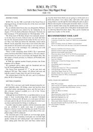
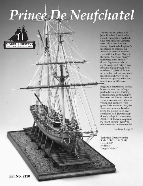
<strong>Prince</strong> <strong>De</strong> <strong>Neufchatel</strong><br />
The War of 1812 began on<br />
June 18 when America declared<br />
war against England.<br />
One of the reasons America<br />
took this action was her<br />
strong objection to England’s<br />
insistence on impressing<br />
American seaman into service<br />
with the Royal Navy. At<br />
the time, America’s “navy”<br />
numbered only one half<br />
dozen frigates and six or<br />
eight sloops and brigs. Great<br />
Britain’s world power fleet<br />
numbered 1,000 sail. It was<br />
no wonder that the over-confident<br />
English viewed the<br />
American upstarts with contemptuous<br />
indifference.<br />
England’s astounding defeat,<br />
however, was due in large<br />
part to her relaxed training<br />
attitude and a continuing reliance<br />
on her former cause for<br />
victory: seamanship. Maneuvering<br />
and gunnery were<br />
given little attention. But, the<br />
American seaman, besides<br />
being too young to be overconfident,<br />
had grown exceptionally<br />
adept in those areas.<br />
All their skills were acquired<br />
by “hard knocks” received<br />
while serving on commercial<br />
(continued page 3)<br />
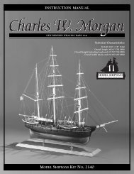
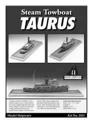
Technical Characteristics<br />
Scale: 3/16” = 1 ft. (1:64)<br />
Height: 23”<br />
Width: 5”<br />
Length: 32-1/2”<br />
Kit No. 2110
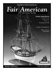
Instruction Manual<br />
9th Century Privateer Hermaphrodite-Schooner<br />
<strong>Prince</strong> <strong>De</strong> <strong>Neufchatel</strong><br />
1812-15<br />
By Robert L. Evans<br />
©Copyright 2005<br />
Model Shipways, Inc.<br />
3850 N 29th Terrace • Hollywood, FL 33020<br />
2
(continued from page 1)<br />
ships that were drawn into petty<br />
skirmishes with French frigates, the<br />
Moors of Tripoli and the many pirates<br />
or privateers that sailed the<br />
waters looking for easy wealth.<br />
And, while England rested on her<br />
laurels, America’s resilient, intelligent<br />
young men were being trained<br />
to the maximum.<br />
Credit for America’s success in<br />
winning the War of 1812 belongs<br />
in part to the many privateers who<br />
signed on to do battle against the<br />
might of England. According to<br />
Falconer’s Dictionary of the Marine<br />
(1768), “Privateers are vessels of<br />
war armed and equipped by particular<br />
merchants, and furnished with<br />
commissions from the State to<br />
cruise against and annoy the<br />
enemy by taking, sinking, or burning<br />
their shipping.” The commission,<br />
authorized by a letter-of-marque,<br />
empowered merchants to appropriate<br />
to their own use whatever<br />
prize (actual capture of a vessel)<br />
they made, as well as receive monetary<br />
allowance for each prisoner<br />
taken.<br />
While on the whole the privateers,<br />
as irregular forces, were certainly<br />
no match for the the British regular<br />
cruisers, they inflicted enormous<br />
damage on the foe. Among four of<br />
the privateers that were most creditable<br />
was the speedy brigantine<br />
<strong>Prince</strong> de <strong>Neufchatel</strong> captained by<br />
J. Ordronaux of New York. A superbly<br />
built vessel of 310 tons, she<br />
mounted 18 guns and originally<br />
possessed a crew of 150 men.<br />
Her most awesome battle occurred<br />
on October 11th just after having<br />
made a very successful cruise. She<br />
had on board 37 prisoners and<br />
$300,000 in goods, but had manned<br />
and sent in so many prizes that<br />
only 40 of her crew remained. With<br />
little warning, the crew found<br />
themselves pursued by the British<br />
frigate Endymion which, during a<br />
calm, dispatched 5 boats containing<br />
111 men. The <strong>Neufchatel</strong> opened fire<br />
on the boats but they were soon<br />
alongside, and the British clamored<br />
aboard the hopelessly undermanned<br />
brigantine. A desperate<br />
battle ensued. The slaughter was<br />
frightful. The British lost with 28<br />
killed, 37 wounded and 10 taken<br />
prisoner. American losses were 7<br />
killed, 15 badly and 9 slightly<br />
wounded, with only 9 men untouched!<br />
This incredible battle with<br />
its miraculous outcome reflected<br />
the highest honor on the American<br />
captain and his crew.<br />
After returning to Boston with her<br />
prize, she was issued a new letterof-marque<br />
and sailed in <strong>De</strong>cember<br />
of 1814 under the command of<br />
Nicholas Millin. On the 26th, she<br />
was spotted and chased by three<br />
British frigates; Leander, Newcastle<br />
and Acasta. <strong>Prince</strong> de <strong>Neufchatel</strong><br />
would have escaped, if not for the<br />
fact that she lost spars by carrying<br />
too much sail. The commodore of<br />
the frigate squadron was so impressed<br />
by the schooner’s speed<br />
that rather than having her condemned<br />
in Halifax, he had her sent<br />
to the <strong>De</strong>ptford Dockyard to be<br />
surveyed. Her lines were taken, but<br />
in handling, her back was broken<br />
on the dock gate sill. This accident<br />
prevented her from being taken<br />
into Royal Navy service and she<br />
was sold off.<br />
One of the most notorious of the<br />
American privateers during the<br />
War of 1812, <strong>Prince</strong> de <strong>Neufchatel</strong><br />
was supposedly built by Christian<br />
Bergh at New York in 1812-13 and<br />
was named for Berthier, one of<br />
Napoleon’s marshalls of the period.<br />
One of the larger privateers. she<br />
measured 107’ 6” at the waterline,<br />
and possessed a speed equal to design<br />
speeds of clipper ships built 40<br />
years later. Because she had a size<br />
and shape that could attain high<br />
speeds and hold more firepower,<br />
her shape was given to a whole<br />
fleet of opium clippers.<br />
Armament for the privateers was<br />
usually sixteen 12-pounder carronades<br />
and two long 18’s as chase<br />
guns. All were carriage mounted to<br />
allow more positioning freedom,<br />
and to accommodate the higher<br />
bulwarks found on the privateers.<br />
3
Construction Stages and Table of Contents<br />
Brief History Cover, pg 3<br />
Credits Pg 2<br />
Before You Begin Pg 5<br />
How to Work With the Plans and Parts Pg 6<br />
Sail Option (Read before beginning construction) Pg 6<br />
What You’ll Need to Start Construction Pg 6<br />
Painting & Staining the Model Pg 7<br />
Stage A: Building the Hull Assembly Pg 8<br />
1. Bulkhead & False Keel Preparation Pg 8<br />
2. Frame Assembly Pg 8<br />
3. <strong>De</strong>ck Plate Mounting Pg 8<br />
4. Bow and Stern Blocks Pg 9<br />
5. Bulkhead Edge Chamfering Pg 9<br />
6. Bulwark Plate Fitting & Mounting Pg 9<br />
7. Transom Pg 10<br />
8. Inner Bulwark Preparation Pg 11<br />
Stage B: Surfacing the Hull Assembly Pg 12<br />
1. Lower Hull Under-planking Pg 12<br />
2. Applying Filler to the Under-planking Pg 12<br />
3. Inboard Bulwarks Pg 13<br />
4. Outer Final Planking Pg 13<br />
5. Planking the Inner Bulwarks Pg 13<br />
6. Outboard Final Planking Pg 13<br />
7. Stern Final Planking Pg 13<br />
8. Lower Hull Final Planking Pg 14<br />
9. Creating Batten Lines on the Lower Hull Pg 14<br />
10. Plank Tapering For the Hull<br />
11. <strong>De</strong>ck Final Planking<br />
12. The Cap Rail<br />
Pg 14<br />
Pg 15<br />
Pg 15<br />
Stage C: Mounting the Hull Pg 16<br />
1. Mounting Board with Two Pedestals Pg 16<br />
2. Launching Ways Pg 16<br />
Stage D: <strong>De</strong>ck Furniture Pg 16<br />
1. Bowsprit & Bitts Pg 17<br />
2. Forward Companionway Pg 17<br />
3. Windlass Bitts (Fore & Main) Pg 17<br />
4. Hatches (Galley, Main & Aft) Pg 17<br />
5. Main Cabin Pg 17<br />
6. Rudder, Mast Openings, Pump Assemblies Pg 17<br />
7. Belaying Pin Racks & Channels Pg 18<br />
8. Gunport Lids Pg 18<br />
9. Bow Pg 18<br />
10. Railing Bitts & Knightheads<br />
11. Armament<br />
Pg 18<br />
Pg 18<br />
Stage E: Mast & Spar Construction Pg 20<br />
1. Assembling the Masts Pg 20<br />
2. Spars & Booms Pg 20<br />
3. Fittings Pg 20<br />
4. Bowsprit Assembly Pg 21<br />
5. Mounting Spars & Booms Pg 21<br />
6. Mounting the Masts & Bowsprit Pg 21<br />
Stage F: Standing Rigging Pg 22<br />
1. Bowsprit Rigging Pg 22<br />
2. Fore-stays Pg 22<br />
3. Shrouds Pg 23<br />
4. Back-stays Pg 23<br />
5. Lifts Pg 23<br />
Stage G: Running Rigging Pg 24<br />
1. Jib Sails Pg 24<br />
2. Stay-Sails Pg 25<br />
3. Gaffs Pg 25<br />
4. Driver Boom Pg 25<br />
5. Spars Pg 25<br />
6. Ground Tackle Pg 26<br />
7. Flag Halyard Pg 26<br />
8. Ship’s Boat Pg 26<br />
Key to Rigging Plan Pg 29<br />
Bibliography Pg 30
BEFORE YOU BEGIN<br />
Great attention has been given to compiling<br />
these instructions so the less experienced<br />
modeler will have a more complete<br />
understanding of the design intent<br />
of the prefabricated parts and fittings in<br />
the kit. Alternately, the more experienced<br />
modeler will find that parts provisions<br />
are flexible enough to allow application<br />
of individual building techniques and sequences<br />
other than those suggested in<br />
this manual.<br />
An attempt has been made in the kit design<br />
to provide materials which lessen<br />
the time and skill required to produce the<br />
finished model. Laser cut parts are used<br />
extensively, particularly for the bulwarks.<br />
This will allow a more accurate<br />
placement of the gun and oar ports. The<br />
laser cut false keel and bulwarks also<br />
give a more accurate shape to the hull.<br />
These prefabricated parts do not, however,<br />
eliminate the individual fitting and<br />
adjustments that must be made during<br />
construction, due to variances in manufacturing<br />
tolerances and the modeler’s<br />
care in construction.<br />
For those familiar with Model Shipway’s<br />
kit of the Fair American, you’ll find construction<br />
of this kit to be somewhat similar.<br />
The topsail schooner rig will be less<br />
involved, but size will present more difficulty.<br />
The hull shape, however, lends itself<br />
to ease of planking. Anyone who<br />
builds this Baltimore Clipper should find<br />
it a satisfying step toward more involved<br />
modeling experiences.<br />
Those of you wanting to expand the details<br />
of your model will find all of the required<br />
additional specifications in the<br />
publications listed in the Bibliography.<br />
Happy modeling!<br />
5
6<br />
HOW TO WORK WITH THE<br />
PLANS AND PARTS<br />
The plans for the <strong>Prince</strong> de <strong>Neufchatel</strong> are<br />
drawn to full 3/16” (1:64) scale. This<br />
makes it easy for the modeler to take<br />
parts dimensions directly from the plans,<br />
as well as check each finished assembly<br />
portion for accuracy. To transfer information<br />
from instructions and plans to actual<br />
parts and materials, the following measuring<br />
tools are almost a must:<br />
1. 6” or 12” Scale calibrated in both English<br />
and Metric measures. (The English<br />
should be divided to 1/64” and also provide<br />
decimal calibrations to .01.” The<br />
Metric should be divided into millimeters.)<br />
To work with the surfaces of the<br />
model, choose a scale made of thin plastic<br />
so it may be bent along the curves.<br />
2. 6” Dividers which will allow one of<br />
the needlepoints to be converted to a<br />
pencil point. A Compass will fill this<br />
need if it has replaceable tips.<br />
3. 6” Vernier Caliper calibrated in both<br />
English and Metric would be a useful addition<br />
to the above tools.<br />
Five Plans are provided:<br />
1. P-001: Fabricated Components listed<br />
and shown in detail<br />
2. P-002: Hull Assembly<br />
3. P-003: Masts and Spars<br />
4. P-004: Rigging <strong>De</strong>tail– shrouds, ratlines,<br />
stays, lifts, halliards, downhauls,<br />
braces & boom rigging<br />
5. P-005: Rigging <strong>De</strong>tail– Clew lines,<br />
sheets, tacks, square sail outline, bow<br />
sprit rigging<br />
Sequential drawings and photos, not necessarily<br />
to scale, will be found throughout<br />
the instruction manual to help describe<br />
the assembly. In addition, a List of<br />
Parts can be found on a separate sheet included<br />
in the kit.<br />
It is strongly suggested that before starting<br />
construction, the modeler go through<br />
these instructions and the contents of the<br />
kit. Examining the kit will serve two purposes.<br />
First, the modeler will become familiar<br />
with the kit contents, and second;<br />
he will be able to determine that all has<br />
been supplied as listed on the enclosed<br />
List of Parts sheet. It is also suggested<br />
that all small fittings and hardware be<br />
sorted into labeled parts boxes or compartments<br />
to avoid loss during the building<br />
process. It’s surprising how familiar<br />
the modeler can become with the kit requirements<br />
by just handling the parts!<br />
Important: If you are planning to mount<br />
sails, read the Sail Option section now so<br />
you’ll be prepared for that final stage.<br />
SAIL OPTION<br />
If you are planning to rig sails on the<br />
model, preparation must be made early<br />
on. Additional blocks will be required for<br />
the bunt lines. Belaying plans should be<br />
layed out for leech lines, stay-sails and jib<br />
sheets. As will be mentioned in the two<br />
sections on rigging, the spares will be<br />
used up and some shifting of the belaying<br />
points may be required. The rigging<br />
of the square sail clews and sheets will<br />
also have to be done as the sails are bent.<br />
Study of the books listed in the bibliography<br />
will aid in building accuracy.<br />
Preparing the Sails: Using the Rigging<br />
Plans as a guide, make paper patterns of<br />
the sails first to be sure that your final<br />
sails will fit properly (see also figures<br />
73a, 73b, 81a and 81c). Also be certain<br />
that the spars are set at their raised position<br />
as shown on the plans. With the patterns<br />
established, you can cut oversized<br />
pieces of cotton balloon cloth. These<br />
should be tinted with wood stain. Min-<br />
Wax “Driftwood” is a good choice, but<br />
stay away from stains with any red in<br />
them, such as mahogany, maple or walnut.<br />
The stained cloth can then be sized<br />
with clear lacquer and ironed flat. Next,<br />
draw panel lines on the sails. Hemming<br />
can be created simply by folding and gluing<br />
the edges. (While the pencil lines will<br />
define the sail structure, stitching the<br />
panel lines and the hems will add more<br />
detail in this scale.)<br />
There are many approaches to making<br />
sails and they have been well described<br />
in various publications. Your choice of<br />
method may be determined by the tools<br />
you have on hand.<br />
WHAT YOU’LL NEED<br />
TO START CONSTRUCTION<br />
The following tools and supplies are recommended<br />
for the construction process.<br />
Modelers who have built before may<br />
have their own favorites.<br />
A. Knives:<br />
1. Set of hobby knives with a quantity<br />
of #ll blades and square and skew<br />
chisel blades<br />
2. Box of single edge razor blades<br />
B. Files:<br />
1. Set of medium needle files<br />
2. Combination medium/coarse<br />
& round/flat rasp<br />
C. Saws:<br />
Razor saw set<br />
D. Clamps:<br />
1. 6 Small C-clamps<br />
2. 12 Wooden, spring clothespins<br />
E. Sandpaper:<br />
Assortment of grits from 100 to 240<br />
F. Boring Tools:<br />
1. Set of miniature drills, sizes 61-80<br />
2. A pin vise<br />
3. Set of miniature reamers<br />
G. Miscellaneous:<br />
1. Small hammer<br />
2. Tweezers<br />
3. Small fine scissors<br />
4. Miniature pliers<br />
a. round nose<br />
b. square<br />
c. diagonal cutters<br />
d. tapered, half-round<br />
5. 1/2” or 3/4” masking tape<br />
H. Finishing:<br />
1. Brushes<br />
a. fine with round and square ends<br />
b. medium with round<br />
and square ends<br />
I. Supplies:<br />
(will be covered in detail in “Finishing<br />
the Model” section and throughout<br />
instructions)<br />
1. Paint<br />
2. Wood stains<br />
3. White glue<br />
4. Super glue<br />
5. Glazes and stains<br />
Note: Miniature power tools such as<br />
drills, sanders and scroll saws will speed<br />
up some work, but are not necessary to<br />
construct this kit.
PAINTING & STAINING<br />
THE MODEL<br />
It may seem strange to begin an instruction<br />
manual with directions on applying<br />
the finishes to the model. Not so! Much<br />
time and effort can be saved, and a more<br />
professional result can be obtained, if the<br />
finishing process is carried out during<br />
construction. Painting of various small<br />
parts, masts and spars should be accomplished<br />
before they are installed on the<br />
model. Painting sequence must be a well<br />
thought out procedure, otherwise you<br />
may have difficulty as you proceed with<br />
assembly. For example, it is easier to<br />
paint a deckhouse or hatch coaming before<br />
it is glued to the deck. Put the parts<br />
aside until they are ready to be installed.<br />
Proper timing in the application of finishes<br />
and the use of masking tape to define<br />
painted edges should eliminate unsightly<br />
glue marks and splotchy stained surfaces.<br />
In the end, following these general<br />
suggestions will be to your advantage.<br />
Your first decision should be to determine<br />
how “finished” you want the model<br />
to be. A more authentic scheme will require<br />
the finishing of internal bulwarks,<br />
railings, transom, mast tops and doublings<br />
and deck furniture. This would entail<br />
using the following color scheme:<br />
1. Red: internal bulwarks, gunport<br />
edges, oarport edges, hatch coamings,<br />
companionway coamings, gun carriages,<br />
pumps, windlass supports, bitts, inside<br />
gunport lids.<br />
2. Black: mast tops, mast doublings, cap<br />
rail, main wale, outside ship’s boat, transom,<br />
bowsprit to doubling, spars, gaffs,<br />
booms and outside gunport lids. Metal<br />
parts such as gun barrels, anchors, cleats<br />
and rings can be finished with metal<br />
blackener or painted.<br />
3. Yellow or gold: beak supports and<br />
structure, name lettering<br />
4. Stains: Oak – deck planking, cabins<br />
and companionways;<br />
Dark Walnut – external hull, keel, stem,<br />
sternpost, inside ship’s boat, rudder;<br />
Natural Pine – unpainted mast sections<br />
To achieve an “all natural look” finish<br />
would require that most parts of the<br />
model be stained Dark Walnut, except<br />
for the deck, which should be stained in<br />
Oak. But even with this natural type<br />
look, a more attractive finish could be obtained<br />
by painting the cap rail and wale<br />
black. This would accent the lines of the<br />
hull. The hardware, guns, etc. could be<br />
left bright or blackened. Hatch coamings<br />
could revert to the Dark Walnut stain.<br />
Remember, each captain had his preferences<br />
and painted accordingly. You will<br />
be the captain of your ship and can do<br />
the same.<br />
Staining & Painting Techniques<br />
The following techniques will improve<br />
whichever finish you choose:<br />
1. Stains should be applied to the part before<br />
mounting. This will eliminate any<br />
interference by glues that may be present<br />
on the surface. It will also prevent the<br />
bleeding of one stain color into another<br />
on an adjacent surface.<br />
2. Paints should be applied to any part<br />
that will abut a surface which is to be a<br />
different color or stain. This will be particularly<br />
useful when joining the inner<br />
bulwark planking and the waterways<br />
with decking surface, and when mounting<br />
wales and the cap rail which are a<br />
different color than the hull or bulwarks.<br />
This step completely eliminates the need<br />
for masking or carefully painting a line.<br />
Some touch-up may be required, but it<br />
will be much easier than cutting an entire<br />
line. Beyond the parts or strakes that define<br />
different finishes, the painting<br />
can be done on the model.<br />
If the parts are pre-finished as suggested,<br />
any differences in gloss or glue marks<br />
will be eliminated by the application of a<br />
final overcoat of glaze or varnish. Whenever<br />
possible, surfaces to be painted<br />
should be placed horizontally to eliminate<br />
“runs” which will ruin the finish.<br />
Pointed brushes are best used for detail<br />
work and the flats will work best on the<br />
larger areas. Do not “build up” paint as it<br />
will hide structural details and could<br />
possibly chip while handling during construction.<br />
<strong>De</strong>tailed painting is best accomplished<br />
by steadying the hand<br />
against the work or other surface and<br />
only using the finger movements to<br />
apply the brush strokes.<br />
Only paints developed for model work<br />
should be used as they have the finer pigments<br />
which will not take away from<br />
surface details. Whenever possible, use<br />
standard colors as mixed by the manufacturer.<br />
This will allow a better match of<br />
color when going from one container to<br />
another.<br />
General finishing techniques require that<br />
any finish should set at least 24 hours before<br />
applying an additional coat or other<br />
treatment. (Each manufacturer will have<br />
a recommendation on drying and setting<br />
times for their products.)<br />
7
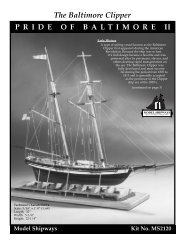
FIG. 1<br />
FIG. 3 FIG. 5<br />
A bulkhead marked and ready for assembly to the<br />
false keel.<br />
FIG. 2<br />
<strong>De</strong>ck plate mounting held with clothespins.<br />
FIG. 4<br />
Bow blocks shaped. Black line is black tape defining<br />
chamfered width of false keel.<br />
FIG. 6<br />
Bulkhead and false keel assembly.<br />
Bow blocks mounted.<br />
Stern blocks mounted.<br />
8<br />
STAGE A<br />
BUILDING THE HULL ASSEMBLY<br />
The Hull Assembly of any model represents<br />
75% of the job. Besides serving as<br />
the support platform for the masts and<br />
rigging, most attention given by the observer<br />
will be directed toward the hull<br />
lines and deck details. For these reasons,<br />
the hull framework should be constructed<br />
with precision, creating a sturdy, true<br />
and perfectly symmetrical showpiece.<br />
The <strong>Prince</strong> de <strong>Neufchatel</strong> hull frame is<br />
made up of 22 bulkheads, a one-piece<br />
false keel and a deck plate. They are all<br />
laser cut to close tolerances, allowing a fit<br />
that should not require any additional<br />
fixtures for alignment when properly assembled.<br />
Extensive use of horizontal waterlines<br />
and vertical centerlines on these<br />
parts are a great help in establishing<br />
what will be the basis for all subsequent<br />
construction.<br />
1. Bulkhead & False Keel<br />
Preparation:<br />
The bulkheads are cut from 1/8”-thick<br />
plywood and are sequentially identified<br />
“A” to “V” from bow to stern (see figure<br />
1). Each of them has shaped extensions<br />
above the deck line to define the height<br />
of the bulwarks and they are grooved to<br />
fit over the 3/16”-thick false keel piece.<br />
(Bulkhead “O” does not extend above the<br />
deck so as to prevent interference with<br />
the gunport openings.) The pre-cut bulkheads<br />
have the deck camber cut in.<br />
Check the keel grooves for an accurate fit<br />
over the false keel. If too small, they<br />
should be widened equally about the<br />
centerline. Before mounting to the keel,<br />
label and mark each bulkhead with a vertical<br />
centerline and a horizontal line perpendicular<br />
to the centerline and through<br />
the deck crown at the bulwarks.<br />
Next, check all bulkhead grooves of the<br />
3/16”-thick plywood false keel to ascertain<br />
that they will accept the 1/8”-thick<br />
bulkheads. The depth of the grooves<br />
should allow each bulkhead to sit with its<br />
center flush with the top of the false keel<br />
piece (see figure 2). Vertical lines should<br />
be drawn to establish bulkhead alignment<br />
on the keel piece at the forward<br />
side of each bulkhead groove.<br />
Note: all groove fits should be close, but<br />
not bind or allow excess movement.<br />
2. Frame Assembly:<br />
Starting from either the bow or stern, sequentially<br />
glue the bulkheads into place<br />
(see figure 2). The center of each bulkhead<br />
should be aligned with the center of<br />
the keel piece, and the horizontal line on<br />
each bulkhead must be set perpendicular<br />
to the vertical side of the keel piece. This<br />
can be checked with a small square. The<br />
bulkhead should also be at a 90-degree<br />
angle to the keel piece. Sequential mounting<br />
is necessary to allow use of the<br />
square for each bulkhead alignment.<br />
Bulkheads can be held with white glue<br />
and clamped with clothespins. When<br />
properly aligned, the joint can be set by<br />
wicking in slow-set cyanoacrylate glue.<br />
A note on glues: White glues are slower<br />
setting and tolerant to parts adjustments.<br />
They tend to fill wood porosity, and this,<br />
along with their moisture content, provides<br />
a stronger bond when an additional<br />
application of cyanoacrylate glue is<br />
combined (for joints that need it). For<br />
more delicate assembly work, this combination<br />
of glues is not recommended,<br />
since some filleting may occur and the<br />
white glue does not always dry clear.<br />
A note on hull symmetry: Eyeballing–<br />
Even though you have carefully marked<br />
and set each bulkhead square on the false<br />
keel, keep eyeing the entire assembly<br />
from stern to bow to assure that no twist<br />
has set in that would result in a warped<br />
deck or cocked transom mounting.<br />
3. <strong>De</strong>ck Plate Mounting:<br />
The sub-deck plate of 1/32”-thick laser<br />
cut aircraft grade plywood is the next<br />
item to be installed to the hull framework<br />
(see figure 3). Draw a centerline on the
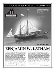
FIG. 7a<br />
FIG. 7b<br />
Good<br />
Plank<br />
BHDS<br />
Bevel too great could<br />
leave as is but better to<br />
add wedge and re-sand<br />
Hump–sand<br />
to dotted line<br />
and recheck<br />
Good<br />
Stern blocks shaped.<br />
Chamfering of the bulkhead edges.<br />
FIG. 8 FIG. 9<br />
Shows after-end of stern blocks which are left<br />
square until transom is installed.<br />
First strake of under-planking at deckplate level.<br />
deck plate from bow to stern. The bulkhead<br />
slots should also have lines drawn<br />
across the deck plate connecting them<br />
from port to starboard. These notches are<br />
deep enough to clear the bulkhead extension<br />
above the deck line. Check their<br />
widths for an accurate fit of the bulkhead<br />
thickness. Widen if too tight, but DON’T<br />
OVERWIDEN THESE SLOTS!!! They accurately<br />
position the bulkheads and<br />
straighten any curvature that may be present<br />
in the false keel piece. The fit of<br />
these slots should be equal to the snug fit<br />
of the keel to bulkhead joints.<br />
The deck plate can be held down to the<br />
deck camber by using clothespins at the<br />
edges of the bulkheads. Be sure the deck<br />
plate centerline is on the center of the<br />
false keel and the mast holes are over the<br />
mast grooves in bulkheads “E” and “N.”<br />
Small nails can be used to hold the plate<br />
in place on the top of the false keel.<br />
White or cyanoacrylate glue is then<br />
wicked into the joint of the bulkheads<br />
and the underside of the deck plate.<br />
4. Bow & Stern Blocks:<br />
When the deck plate is set, bow and stern<br />
blocks of medium grade balsa are fitted<br />
(see figures 4 and 6). As sized, the grain<br />
of the bow blocks must run fore and aft,<br />
and the grain of the stern blocks must<br />
run vertically. Surfaces of these blocks<br />
have to be chamfered* (see figures 5 and<br />
7a). This will allow a snug fit into the corners<br />
formed by the deck plate, false keel<br />
and bulkhead “A” at the bow; and bulkhead<br />
“V” at the stern.<br />
*Note: Chamfering means to cut or bevel<br />
the corner at an inclined angle for working<br />
the wood to a particular shape.<br />
5. Bulkhead Edge Chamfering:<br />
The bulkhead edges have to be chamfered<br />
to properly accept the under planking<br />
and give a true look to the hull (see figure<br />
7b). The <strong>Prince</strong> de <strong>Neufchatel</strong> hull does not<br />
require extensive work in this area. The<br />
bulkheads that require the most chamfering<br />
are “A, B, C, D, E, & F” at the bow<br />
and “P, Q, R, S, T, U & V” at the stern.<br />
The ten amidships from “G” to “O” can<br />
have square edges. To maintain the hull<br />
shape, the after corners of the bow bulkheads<br />
and the forward corners of the<br />
stern bulkheads to be chamfered should<br />
be marked with a pen or pencil. When<br />
chamfering, these corners should never<br />
disappear. The bulkhead thickness of<br />
1/8” was selected to allow ease of chamfering,<br />
as well as provide a greater number<br />
of bulkheads for a better hull line.<br />
The best tools for chamfering this model<br />
are files. Flats can be used on the convex<br />
edges and rounds are the better choice for<br />
the concave edges at the stern. For these<br />
narrower bulkheads, knife cuts should<br />
not be required. When proceeding with<br />
the chamfering, you will find that the<br />
bow and stern blocks will be altered to<br />
maintain a true hull line all the way to the<br />
stem and stern post lines. This work will<br />
test your ability to set a fair curve line on<br />
the hull. It can only be done well with patience.<br />
Practice helps, but this may be<br />
your first try ... so, easy does it!<br />
The last chamfering to be done is the<br />
shaping of the false keel piece from bulkhead<br />
“D” to the bow and bulkhead “P”<br />
to the stern (see figures 5 and 8). Chamfer<br />
the false keel from its original 3/16”<br />
thickness to 1/8” thickness all the way to<br />
the deck plate at the bow and to the stern<br />
block at the stern. This tapering will accommodate<br />
the walnut stem, keel and<br />
sternpost pieces which will be added before<br />
applying the final hull planking.<br />
6. Bulwark Plate Fitting<br />
& Mounting:<br />
The frame is now ready for the first strake<br />
of under-planking that is required to properly<br />
fit the bulwark plates (see figure 9).<br />
It is 1/16” x 3/16” basswood that will also<br />
be used for the under-planking of the lower<br />
hull. Mount it even with the top edge of<br />
the deck plate from bow to stern. It can be<br />
held in place at each bulwark with small<br />
nails and glue. Spring clamps will work<br />
best at the bow. (Wet forward ends of<br />
these strips to ease bending at the bow.)<br />
9
FIG. 10<br />
FIG. 12 FIG. 14<br />
Bulwark plate clamped in position to determine<br />
bottom edge line.<br />
FIG. 11<br />
Clamping at stern showing variety of clamps that<br />
can be used to hold hull flair curvature.<br />
FIG. 13<br />
The transom plate looking inboard aft.<br />
Bulwark plate clamped during gluing.<br />
Starboard bulwark plate mounted.<br />
10<br />
The bulwark plates are laser cut from<br />
1/32” plywood. These pieces have the<br />
gunport and oarport openings cut into<br />
them (see figure 10). The bow, stern and<br />
bottom sides have been left oversized to<br />
allow fitting to the framework you have<br />
built. The top edge has been accurately<br />
shaped to the top bulwark line. The gunport<br />
openings are cut slightly undersize<br />
to allow proper sizing to the gunport<br />
frames which will be mounted later. The<br />
first thing to do is establish which are the<br />
lower edges of the bulwark plates.<br />
The gunport openings will help. They are<br />
numbered 1 through 11 from bow to<br />
stern. Gunports 5 and 11 should be centered<br />
vertically between bulkhead extensions<br />
“I” and “J” and “T” and “U” respectively.<br />
The top edge of the bulwark<br />
plate has to be 25/32” from the top of the<br />
deck plate at bulkhead “T” and 31/32” at<br />
bulkhead “I.” An additional height check<br />
can be made at bulkhead “A.” It should<br />
be 13/16.” With the bulwark plates set at<br />
these dimensions and clamped in place, a<br />
line should be drawn inboard along the<br />
bulwark plate at the top of the deck plate.<br />
The bulwark plate can be removed and<br />
cut to this line, which establishes its bottom<br />
edge for assembly.<br />
The plates are then remounted to the bulkhead<br />
extensions with clamps at the proper<br />
fore and aft, and vertical settings and<br />
glued in place with slow-set Super glue<br />
(see figure 11). They should be clamped at<br />
each bulkhead to be sure they conform to<br />
the tumblehome and flair curvatures along<br />
the hull (see figure 12). It can be advantageous<br />
to glue in the bottom edges before<br />
clamping to the bulkhead shapes above<br />
deck. To aid in positioning these bulwark<br />
plates, you should refer to the plans and<br />
use the following table as a guide (Also ...<br />
the bow ends tend to flair upward and<br />
should be held firmly in place):<br />
Bulkhead Top edge above deck plate<br />
A................................13/16”<br />
B....................................“<br />
C................................27/32”<br />
D..................................7/8”<br />
E................................ 31/32”<br />
F.....................................“<br />
G....................................“<br />
H....................................“<br />
I......................................“<br />
J......................................“<br />
K................................15/16”<br />
L.....................................“<br />
M...............................29/32”<br />
N............................... 27/32”<br />
O..................................7/8”<br />
P.....................................“<br />
Q................................27/32”<br />
R....................................“<br />
S.................................13/16”<br />
T................................ 25/32”<br />
U..................................3/4”<br />
V................................11/32”<br />
Note: These dimensions are taken along<br />
the outer curved surfaces of the bulwark<br />
extensions which are longer than<br />
the vertical height from the edge of the<br />
deck plate.<br />
These dimensions are for reference only<br />
and depend upon the accuracy of the<br />
deck plate level. A true line is more important<br />
than an actual conformation to<br />
any reference dimension. In addition,<br />
the bulkhead extensions should be<br />
aligned externally to give a true line to<br />
the bulwarks (see figure 13). If some are<br />
below a true line, they should be<br />
shimmed with 1/8” wide basswood<br />
stock. Those that may be too “fat”<br />
should be trimmed down. The 3/16”<br />
width of these extensions will accommodate<br />
any trimming easily. Gross<br />
bumps or indentations are not the intent<br />
of the ship designer, builder, historian,<br />
kit designer or modeler.<br />
7. Transom<br />
The transom piece is also laser cut from<br />
1/32” plywood. Its top is cut to the design<br />
curvature and the gunports are also<br />
cut as they were in the bulwark plates<br />
(see figure 14). The bottom and side<br />
edges have been left longer to allow fitting<br />
to your assembly. This piece should<br />
have a vertical centerline drawn on it between<br />
the gunports.
FIG. 15<br />
FIG. 17<br />
Stern blocks filed to the slope of transom.<br />
Gun and oar port frames amidships.<br />
FIG. 16 FIG. 18<br />
Gunport frame clamped at bow.<br />
1/16” square filler strips amidships.<br />
Align the transom center with the deck<br />
centerline and the top edge with the aft<br />
top corners of the bulwark plates. A line<br />
drawn across the deck plate will define<br />
the bottom edge of the transom piece.<br />
When cut to this line, it can be realigned,<br />
held with tape and glued in place along<br />
the bulwark and deck plates. The port<br />
and starboard edges can then be trimmed<br />
down flush with the after ends of the bulwark<br />
plates (see figure 15).<br />
If your frame assembly is square and<br />
level from bow to stern, the transom<br />
will be square if properly aligned. Its<br />
shape may have to be altered to give<br />
this squareness and alignment with the<br />
bulwark plates. If the shape needs to be<br />
altered, be sure to keep the transom<br />
symmetrical from port to starboard, as<br />
nothing shows up with more stigma<br />
than the transom if it is tilted.<br />
8. Inner Bulwark Preparation<br />
Giving the bulwarks the proper thickness<br />
for support and the framing for any<br />
openings is the last bulwark detail chore<br />
to be done before starting the hull surfacing.<br />
Frames for the gunports and oarports<br />
have been laser cut from 1/16” plywood.<br />
The gunport frames are opened to<br />
the proper size and must be centered<br />
over the openings cut in the bulwark<br />
plates. They should be clamped when the<br />
glue is setting to hold them to the curva-<br />
ture of the bulwarks (see figure 16). The<br />
oarport frames are also cut to an accurate<br />
size and should be glued over their<br />
matching openings in the bulwark plates.<br />
The bulwark gunport openings can be<br />
cut to the inner edges of the gunport<br />
frames with a #11 blade. The oarport<br />
openings can be filed to even edges with<br />
a square miniature file (see figure 17).<br />
The transom gunports are treated in the<br />
same manner as the bulwark gunports.<br />
Any framing that may extend over the<br />
top of the bulwarks or butt into a bulwark<br />
extension can be cut to a proper fit.<br />
These frames establish the bulwark thickness<br />
but do not control thickness at the<br />
top and bottom edges.<br />
For any long top or bottom edge opening<br />
between the frames, the support for the<br />
railing and the inner bulwark planking is<br />
supplied by 1/16” square basswood strip<br />
stock (see figures 18 and 19). The strips<br />
mounted at the deck level also provide a<br />
supporting gusset to the bulwark plates<br />
when the bulkhead extensions have been<br />
cut down to the 1/16” thickness at a later<br />
stage of construction.<br />
At the bow are additional strips to support<br />
the inner planking around the curve.<br />
And at the forward lower end, 1/16”-<br />
thick plates are added in the area where<br />
the hawse holes should be drilled 1/8” in<br />
diameter (see figure 20 and plans).<br />
FIG. 19<br />
Filler strips and gunport frames on transom.<br />
FIG. 20<br />
Filler strips and hawse pipe plate at bow.<br />
11
FIG. 21<br />
FIG. 23 FIG. 25<br />
Bow under-planking below bulwarks. Bow completely covered with under-planking. Under-planking at stern clamped to false keel.<br />
FIG. 22<br />
FIG. 24<br />
FIG. 26<br />
Bow under-planking ready for stealers.<br />
Under-planking faired to false keel.<br />
Stern under-planking below bulwarks.<br />
12<br />
STAGE B<br />
SURFACING THE HULL ASSEMBLY<br />
What follows are the steps explaining<br />
how to properly plank the various areas<br />
of the hull from the keel up to the bulwarks<br />
and its railing. This will include<br />
various finishing requirements for those<br />
parts of the hull assembly and planking<br />
which will make finishing a lot less difficult.<br />
Each step will advise the type of finish<br />
required for either the painted or “all<br />
natural look” options. This particular<br />
hull shape is one of the easiest to plank<br />
and should cause little difficulty.<br />
1. Lower Hull Under-Planking<br />
The first surface to be covered is the<br />
lower hull below the first planking strake<br />
and below the bulwark plates (see figures<br />
21-Bow and 26-Stern). All strakes are<br />
1/16” x 3/16” basswood and require no<br />
finish before mounting. The only purpose<br />
for this planking is to provide a surface<br />
for the second and final layer of<br />
planking. For this reason, you can save<br />
time by not worrying about tapering<br />
planks toward the bow unless you want<br />
the practice. All initial applications of<br />
planking are left full width and allowed<br />
to take a natural line along the lower hull<br />
starting initially at the top.<br />
Other strakes can be laid along the false<br />
keel bottom even with the 1/8” width<br />
that was chamfered when the hull frame<br />
assembly was built (see figure 25-Stern).<br />
As you work up from the bottom and<br />
down from the top, there will be tapered<br />
openings left in the hull areas. These<br />
openings should be filled with “stealers”<br />
(“short lengths of plank worked in<br />
among other strakes to facilitate rounding<br />
off in parts of great curvature”).<br />
Stealers were and are still used in the<br />
planking of life-size ships. These stealers<br />
can be made as required from the planking<br />
material (see figures 22-Bow and 27-<br />
Stern). Doing this step affords the modeler<br />
additional practice that will be helpful<br />
when it comes time to apply the final<br />
planking surface.<br />
2. Applying Filler<br />
to the Under-Planking<br />
When finished with the under-planking,<br />
apply filler to any small cracks that may<br />
exist. This will give a uniform surface for<br />
the next layer (see figure 23-Bow).<br />
When the glue and filler have set, usually<br />
overnight, shape the under-hull by filing<br />
and sanding. Flat files can be used on the<br />
convex surfaces and rounded files will<br />
work best on the concave areas. The planking<br />
must be faired into the 1/8” width of<br />
the false keel edge (see figures 24-Bow, 28-<br />
FIG. 27<br />
Stern under-planking ready for stealers.<br />
FIG. 28<br />
Under-planking faired to false keel.
FIG. 29<br />
FIG. 31 FIG. 33<br />
Under-planking at amidships, ready for keel and<br />
final planking.<br />
Inner final planks clamped into place on bulwarks.<br />
The inner planks painted on the bulwarks.<br />
FIG. 30 FIG. 32<br />
Inner under-planking across transom. Cut-down<br />
bulkhead extensions can be seen on bulwarks.<br />
Amidships inner final planking before trimming to gunport openings.<br />
Stern and 29-Amidships). It should also be<br />
leveled with the bulwark plates along the<br />
deck edge. Any nails that have been used<br />
to hold the planking should be filed off as<br />
you shape the hull. If not, they can be dug<br />
out with a pair of fine side-cutters. This<br />
final shaping should ready the hull for the<br />
external planking.<br />
3. Inboard Bulwarks<br />
The bulwarks located inboard can now<br />
be prepared for planking. The bulkhead<br />
extensions above-deck are all 3/16”<br />
wide. They must be cut down to the gunport<br />
and oarport thickness of 1/16” (see<br />
figure 30). This will allow the inboard<br />
bulwark planking to set properly against<br />
the various port frames along the inside<br />
of the bulwark plates. These extensions<br />
also should be cut flush to the deck plate.<br />
4. Outer Final Planking<br />
All outer planking, except for the deck, is<br />
.021” x 5/32” (.5 x 4 mm) walnut. The<br />
deck planking is 1/32” x 1/8” basswood.<br />
To avoid glue marks, all of these strips<br />
should be finished first before mounting.<br />
Stain the walnut planking “walnut” and<br />
the basswood deck strips “oak.” The<br />
wale is made from 1/16” x 3/16” (1.5 x 5<br />
mm) walnut and also should be stained<br />
“walnut.” This prepares all of the external<br />
planking for mounting regardless of<br />
your choice of finishes.<br />
5. Planking the Inner Bulwarks<br />
Because of the optional choice of painting,<br />
the inner bulwarks must be planked first.<br />
Planking strakes are applied from the<br />
deck plate upwards (see figure 31). Planking<br />
should be sized to the edges of the<br />
gunports, but can be run across the oarports,<br />
which are better opened after<br />
planking is completed (see figure 32).<br />
When the inner planking is done, open all<br />
ports and even up the edges (see figure<br />
33). The inner bulwarks and port edges<br />
should be painted now before the outer<br />
bulwark planking is started. If using the<br />
“all natural look” finish, the port edges<br />
should be stained at this point.<br />
6. Outboard Final Planking<br />
Outboard planking begins with the wale<br />
(see figure 34). It should be mounted<br />
with its top edge even with the bottom of<br />
the bulwark plate. If you are going to<br />
paint, the wale should be painted in<br />
place on the hull before continuing with<br />
the final planking. The wale is carried<br />
across the stern at deck level and this also<br />
should be painted if desired.<br />
7. Stern Final Planking<br />
Final planking starts at the stern, beginning<br />
first with the wale and continuing<br />
up to the top of the bulwarks (see figure<br />
35). Cut all strakes at the gunports, but<br />
FIG. 34<br />
The wale painted black. Inner bulwarks paint can<br />
be seen around edges of gunports.<br />
FIG. 35<br />
Outer transom final planking.<br />
13
FIG. 36<br />
FIG. 39<br />
Final planking of bulwarks amidships above wale.<br />
FIG. 37<br />
FIG. 38<br />
The keel amidships with one of the strengthening<br />
finishing nails showing.<br />
FIG. 40<br />
14<br />
Three laser-cut stem pieces.<br />
cover the oarports (see figure 36). The<br />
oarports are to be opened after final<br />
planking is complete, just as they were<br />
after the first layer of planking.<br />
8. Lower Hull Final Planking<br />
Before beginning the final planking of the<br />
lower hull, mount the keel, stern post<br />
and stem pieces to the false keel (see figures<br />
37 and 38). They are wider than the<br />
keel pieces, which will provide the rabbet<br />
(groove to receive plank edges) needed<br />
for planking at the bow and stern. These<br />
parts should be stained “walnut” before<br />
mounting. The keel piece should be<br />
nailed to the bottom of the false keel in<br />
addition to using glue (see figures 39 and<br />
40). Larger finishing nails can be used<br />
here, but to prevent the keel from splitting,<br />
drill holes for the nails before driving<br />
them into the wood.<br />
The stem mounted to the false keel.<br />
9. Creating Batten Lines<br />
on the Lower Hull<br />
For the hull below the wale to achieve a<br />
scale-like appearance, that area should be<br />
divided into three sections by battens before<br />
laying the final planking (see figure<br />
41). This procedure is described in the<br />
Planking Manual (included in the kit).<br />
Since there is already a hull surface provided<br />
by the first layer of planking, narrow<br />
strips of chart tape can be substituted<br />
for wooden battens. They will be easier<br />
to work around. After creating the batten<br />
divisions, plank the upper and lower<br />
sections first, then finish with the center<br />
section (see figure 42).<br />
10. Plank Tapering For the Hull<br />
The <strong>Neufchatel</strong> hull allows the simplest<br />
plank tapering. From amidships to the<br />
bow, each strake is tapered from its full<br />
width down to 1/16” (see figure 43). It is<br />
best to do this tapering off the ship on full<br />
length strips. From amidships aft, all<br />
planks are left full width, and stealers will<br />
be required (see figures 44, 45 and 46).<br />
All planking can be attached with a thin<br />
layer of white glue to hold the tougher<br />
areas. Those planks which curve around<br />
the bow should be soaked in water and<br />
held to a form, such as a jar lid, until they<br />
dry. This makes the bow planking proceed<br />
much faster.<br />
To further improve the scale look, each<br />
strake should be divided into scalelengths<br />
of 4” representing approximately<br />
21 feet. These divisions are best cut after<br />
each strake is applied, and before the<br />
next is set into place. In total, there<br />
should be 21 strakes from keel to wale.<br />
Refer to the Planking Manual for the<br />
proper spacing of plank “ends” from<br />
strake to strake. Strake ends tucked into<br />
the rabbet at bow and stern will give a<br />
The stern post and the shape of the after-end<br />
of the keel.<br />
FIG. 41<br />
Batten lines created on the lower hull with tape.<br />
FIG. 42<br />
Final planking on the lower hull.
FIG. 43<br />
FIG. 45 FIG. 47<br />
Final planking on bow showing tapering.<br />
Final planking on stern nearly completed.<br />
Start of deck final planking showing guide strip<br />
on centerline.<br />
FIG. 44 FIG. 46<br />
FIG. 48<br />
Final planking on the lower stern showing the first<br />
stealer position.<br />
Final planking amidships.<br />
A method of forming cap rail strips.<br />
very realistic appearance. For those with<br />
more ambition, treenails* can be added to<br />
the butt ends of the planks.<br />
When hull final planking is completed,<br />
another coat of stain will even out the<br />
finish.<br />
*Treenails are easily made from round tapered<br />
toothpicks which can be glued into<br />
any size hole and clipped off. Smoothing<br />
of the surface may require refinishing.<br />
11. <strong>De</strong>ck Final Planking<br />
Returning to above deck, the oak stained<br />
basswood strips will be used to cover the<br />
deck base plate. A first strake should be<br />
laid full length down the center line of<br />
the hull (see figure 47). Be sure to drill<br />
small holes at the mast openings or they<br />
will be lost as the planking continues.<br />
The next planks will fill the areas between<br />
hatch and cabin openings in the<br />
deck plate. The remainder of the plank<br />
strips can be cut into 4” lengths to be laid<br />
in a three-step pattern. Save some strips<br />
to make those planks which may require<br />
a little longer length to fill an area. (No<br />
real deck would ever have a one or two<br />
foot long plank. Once again, you eager<br />
beavers can add treenails if desired.) The<br />
deck should be planked right out to the<br />
bulwarks, but does not require an exact<br />
fit at the edges, since this joint will be<br />
covered by the waterway.<br />
The waterway is made of 1/4-round<br />
stock and should be painted red or<br />
stained “walnut” before mounting. It<br />
should be soaked and curved at the bow<br />
end before finishing and mounting. It<br />
will run the length of the bulwarks and<br />
across the stern.<br />
12. The Cap Rail<br />
To maintain a smooth curvature, the cap<br />
rail around the top of the bulwarks is<br />
made from 5/64” x 5/64” ( 2 x 2 mm)<br />
walnut strip stock. The cap rail is three<br />
strips wide with the middle centered on<br />
the bulwark top.<br />
Those portions of the rail stripping that<br />
cover the bow should be soaked and set<br />
around a form to dry (see figure 48). All<br />
strips should be finished before mounting<br />
(see figure 49). The painted version<br />
should be done in black and the “all natural<br />
look” stained “walnut.”<br />
The first rail strip to be mounted is the<br />
center strip. To it, the inner and outer<br />
strips are applied (see figure 50a). Top<br />
corner edges should be rounded and the<br />
top smoothed. Next, refinish the cap rail<br />
in the areas that were sanded. For detail,<br />
you can cut scarf lines every twenty<br />
scale-feet or so. (For those who are using<br />
the “all natural look” finish, pick rail<br />
strips that are alike in color.)<br />
This completes the Basic Hull Assembly.<br />
FIG. 49<br />
Bow cap rail strips ready for mounting.<br />
FIG. 50a<br />
Outer cap rail strips clamped for gluing.<br />
15
FIG. 50B<br />
The model on launching ways shown at a more completed stage of construction.<br />
16<br />
STAGE C<br />
MOUNTING THE HULL<br />
Before proceeding with additional work<br />
it is best to mount the hull. This step will<br />
help prevent details from becoming damaged<br />
during handling and will allow you<br />
to make any alignments that require a<br />
true waterline. Proper mounting of the<br />
hull is very important and will allow the<br />
accurate building and aligning of the remainder<br />
of the model. While any modeler<br />
can devise his own mounting, there<br />
are two commercial types of mounting<br />
available to you.<br />
1. Mounting Board with<br />
Two Pedestals (not included)<br />
The first is the traditional mounting<br />
board with two brass pedestals. This requires<br />
that holes be drilled through the<br />
keel into the false keel. The first hole<br />
drilled for the <strong>Prince</strong> de <strong>Neufchatel</strong> should<br />
be 5 1/2” from the aft end of the keel.<br />
The second hole should be spaced 8”<br />
from the first. This spacing, along with<br />
same sized pedestals, will give a proper<br />
set to the waterline. A 20” x 4 1/2” walnut<br />
baseboard will give adequate support.<br />
Screw holes in the baseboard also<br />
should be spaced 8” apart on the centerline<br />
and 6” from either end.<br />
When drilling the keel for the pedestal<br />
mounting screws, it is best to clamp<br />
wood strips on either side of the keel to<br />
prevent it from breaking out during<br />
drilling. Any thin walls will be supported<br />
by the pedestals when they are mounted<br />
between the keel and the baseboard. The<br />
screw heads at the bottom of the baseboard<br />
should be countersunk so they<br />
won’t protrude, but will instead provide<br />
a flush surface.<br />
Be sure to drill the screw holes vertically<br />
(port to starboard) as they will determine<br />
the level of the hull abeam. When inserting<br />
the screws, apply a coating of glue to<br />
help their holding power in the plywood<br />
false keel.<br />
2. Launching Ways<br />
(included in the kit)<br />
The second type of mounting that can be<br />
employed is the launching ways, which<br />
are most suitable for a model without<br />
sails (see photo 50b). It is supplied in kit<br />
form with instructions. Drilling of the<br />
keel is still required to apply the rods<br />
that anchor the model to the ways. In addition,<br />
there have to be hull props for a<br />
model the size of the <strong>Prince</strong> de <strong>Neufchatel</strong>.<br />
The launching ways are easily assembled<br />
and should be mounted on a minimal<br />
board size of 24” x 6.” (Expanding the<br />
size of the board will allow you to create<br />
a mini-diorama comprised of boat yard<br />
ground activity.) To achieve the proper<br />
waterline level the ways should rise 3/4”<br />
from stern to bow end over the 24.”<br />
Note: It is recommended that either<br />
choice mounting piece be finished before<br />
mounting the Hull Assembly into place.<br />
During mounting, be sure that the rails of<br />
the hull are level with the mount. Future<br />
alignments, especially the masting, will<br />
be gauged from this base.<br />
STAGE D<br />
DECK FURNITURE<br />
The Baltimore Clippers of the War of 1812<br />
were rather hastily built and had only a<br />
single weather deck. Because of this<br />
arrangement, only the most essential<br />
structures were incorporated in order to<br />
create the least interference with armament<br />
and larger crews. From bow to<br />
stern, the <strong>Prince</strong> de <strong>Neufchatel</strong> provided a<br />
fore grid platform with belaying pins aft<br />
at rail level, cat heads for ground tackle,<br />
bowsprit bitts, a focs’l (pronounced<br />
fokes’l which is the forecastle or forward<br />
deck popularly known as the space below<br />
cabin for crew) companionway, a simple<br />
anchor windlass with support bitts, galley<br />
hatch, amidships cargo hatch and a smaller<br />
winch forward of the mainmast (see
FIG. 51<br />
FIG. 53 FIG. 55<br />
Basic blocks created for deck furniture, hatches<br />
and cabins.<br />
FIG. 52 FIG. 54<br />
Galley hatch with stack on forward deck.<br />
Completed cabin and tiller aft. Open gunport lids<br />
can be seen.<br />
Forward companionway in place.<br />
Main hatch, pumps, aft hatch and basic cabin assembly (from right to left).<br />
figure 51). Aft of the main mast are the<br />
bilge pumps, a smaller loading and ventilating<br />
hatch and a main cabin with a companionway<br />
forward of the tiller.<br />
This section will also include fabrication<br />
of the gunport lids, channels with deadeyes<br />
and chain plates, and the belaying<br />
pin racks inboard abeam the fore and<br />
main masts.<br />
When assembling and mounting these details<br />
all finishing, paint or stain, should be<br />
applied before any glue touches the wood.<br />
1. Bowsprit & Bitts<br />
At the very bow an opening must be cut<br />
to accept the bowsprit which is nominally<br />
1/2” in diameter. The bitts should be<br />
assembled and mounted aft of it (Figures<br />
56 and 60 show these details at more<br />
completed stages of construction). These<br />
bitts, as well as others, should be pinned<br />
into the deck using the small brass nails<br />
provided. Insert the nails into the feet of<br />
the bitts, cut off the nail heads, leaving a<br />
portion of the shaft, and mount them into<br />
holes which have been drilled into the<br />
deck. The bowsprit may be mounted at<br />
this time.<br />
2. Forward Companionway<br />
The forward companionway is created<br />
with a balsa block set into the most forward<br />
opening of the deck (see figure 52). It<br />
should be planked with the .021” x 5/32”<br />
walnut planks. Trim the vertical corners<br />
with the 3/32” basswood angle and the<br />
base with 5/64” square walnut. Fashion<br />
the top out of two strips of walnut using<br />
brass strips to represent the hinges.<br />
3. Windlass Bitts (Fore & Main)<br />
Mount these upright supports in the<br />
same manner as the bowsprit bitts (see<br />
figure 56 for fore windlass bitts, and figure<br />
60 which shows catheads and rail<br />
bitts at the bow).<br />
4. Hatches (Galley, Main & Aft)<br />
All three deck hatches are constructed in<br />
the same manner (see figures 53 and 54).<br />
Cut 1/8”-thick basswood to fit each<br />
hatch opening in the deck. Paint them<br />
black and assemble grid strips to fit and<br />
glue onto the plate. This assembly should<br />
then be set, leveled and glued into the<br />
appropriate deck opening. The stained<br />
grid with the black backing gives a look<br />
of depth. Surround each of the deck<br />
hatches with a coaming of 1/16” x 1/4”<br />
basswood; either stained or painted.<br />
Note: The galley hatch is located aft of<br />
the foremast and has added detail in the<br />
form of a galley stack (see figure 53).<br />
Cover the hatch’s forward end with a<br />
solid plank as indicated in the plans and<br />
mount the stack on it.<br />
Note: An oddball hatch is located forward<br />
where the port and starboard rails<br />
meet. Use the grid as before and cut the<br />
hatch to shape. Mount 9 belaying pins in<br />
the after side and glue into place (see<br />
figure 56).<br />
5. Main Cabin<br />
Shape the main cabin from the larger<br />
balsa block to fit the deck opening. Plank<br />
it, as well as the sides of the companionway<br />
and the skylight, with the .021” x<br />
5/32” walnut (see figure 55). The cabin<br />
and companionway tops should then be<br />
covered with the scored sheet. Next,<br />
paint the top of the skylight black and<br />
then apply the 1/32” square framing.<br />
This assembly should then be set into the<br />
deck and the corners trimmed with angle<br />
stock. Then place 5/64” square molding<br />
around the bottom of the cabin at deck<br />
level. Finally, assemble the companionway<br />
door using boards slipped into a<br />
vertical frame with a latch at the top.<br />
6. Rudder, Mast openings,<br />
Pump Assemblies<br />
At the rudder post and mast openings,<br />
plates of 3/64” (l mm) walnut should be<br />
mounted (see figures 56 and 57). Mount<br />
the two pump assemblies at the rear corners<br />
of the mainmast plate (see figure 54).<br />
After shaping its post, insert the rudder<br />
17
FIG. 56 FIG. 57<br />
Rudder and fittings. “Rivets” are white glue dots<br />
that were painted black when dry.<br />
FIG. 58<br />
Completed outfitted bow with carronades, forward bitts, bow grid and fore windlass.<br />
Starboard main mast belaying pin rack. Breech<br />
ropes can be seen on carronades.<br />
18<br />
into the opening as indicated. Rudder<br />
hinges can be made from the 3/32” wide<br />
brass strip. Form the tiller from the basswood<br />
strip and mount it to the top of the<br />
rudder post (see figure 55).<br />
7. Belaying Pin Racks<br />
& Channels<br />
While not actually part of the deck furniture,<br />
the belaying pin racks and channels<br />
with their fittings can be mounted at this<br />
time. The belaying pin racks lay inboard<br />
beside each of the masts (see figure 58).<br />
Mount them at the bottom edge of the inboard<br />
rail overhang. Drill the belaying<br />
pin holes after mounting the racks. Next,<br />
position and mount the channels evenly<br />
with the belaying pin racks on the outboard<br />
rail overhang. Drill the openings in<br />
the channels that will eventually accept<br />
the deadeye/chain plate assemblies.<br />
Glue the belaying pins into the racks.<br />
Next, insert the deadeye assemblies<br />
through the channels (see figure 59).<br />
They will be pinned to the hull sides, but<br />
have to be aligned with the mast tops<br />
first. To simulate this, set false masts into<br />
the deck and align the chain plates with<br />
string attached to the proper height on<br />
the false mast. The chain plates must then<br />
be anchored with brass nails. Nail these<br />
into the hull.<br />
8. Gunport Lids<br />
Because the hull is securely mounted for<br />
safe handling, you can now introduce the<br />
gunport lids without fear of breaking<br />
them (see figure 59). The gunport lids<br />
and frames are laser cut pieces with the<br />
lids located juxtaposed inside the frames.<br />
Paint the lids red or stain them. Next,<br />
plank them horizontally with the outer<br />
hull walnut strip material. Then remove<br />
the loops from the tops of the brass<br />
hinges and blacken them. Glue them to<br />
the lids and paint the outside of the lids<br />
black. (If you’re doing the “all natural<br />
look” finish, black hinges only with the<br />
natural wood is preferred.)<br />
The aft two port lids may be positioned<br />
closed, but the remainder forward should<br />
be left open. Each opened lid is fitted into<br />
the gunport against the top edge and<br />
glued perpendicular to the hull surface.<br />
(Opened gunport lids can be seen in figures<br />
55 and 56.)<br />
9. Bow<br />
The stem is supported by two gussets.<br />
These are made from 3/64” thick walnut<br />
shaped to fit the stem and hull. Notice<br />
how they curve upward toward the end<br />
of the stem. Next, the catheads are made<br />
from 5/32” (4 mm) square walnut stock.<br />
They represent double blocks for the<br />
ground tackle and should be drilled.<br />
When at sea, the <strong>Prince</strong> de <strong>Neufchatel</strong> did<br />
not mount a bow decoration, therefore,<br />
the only trim is the stem framing which<br />
is made of basswood strip stock. Paint it<br />
yellow. Finally, the hawse pipes should<br />
be set into holes drilled into the forward<br />
bulwark. These will lead the anchor rope<br />
back to the forward windlass and then<br />
aft to the same openings in the deck beside<br />
the forward end of the main hatch<br />
(see figure 60).<br />
10. Railing Bitts & Knightheads<br />
These can be mounted now and the additional<br />
eyebolts that will be required in<br />
the rigging will be covered in the rigging<br />
section (see figure 60).<br />
11. Armament<br />
All 16 carronades and 2 long gun assemblies<br />
should be built, mounted and<br />
rigged at this time (see figures 61, 62a,<br />
62b, 62c, 62d and 62e). Carriages should<br />
be either stained or painted red. The<br />
Rigging Manual shows complete rigging<br />
details. Kit supplies only provide eyebolts<br />
and line for breech ropes. The eyebolts<br />
should be inserted into drilled<br />
holes 1/4” outside the edges of each<br />
gunport. Additional rigging of the guns<br />
will demonstrate the crowded condition<br />
of the deck of this ship which was built<br />
as a fighting machine.
FIG. 59<br />
FIG. 62b<br />
Trunnion &<br />
trunnion cap<br />
1/4”<br />
LONG GUN – 2 REQUIRED<br />
Barrel trunnion 7/16” lg–2 req, 1/16” dia. brass<br />
Wheel axle 3/4” lg–4 req, 1/16” dia brass<br />
Carriage side spacers 1/16” x 1/4” x 1/4” lg, basswood– 4 req<br />
Carriage side<br />
Axles<br />
CARRONADE – 16 REQUIRED<br />
Barrel trunnion 9/16” lg–16 req, 1/16” dia. brass<br />
Rear wheel axle 1” lg–16 req, 1/16” dia brass<br />
Front axle 13/16” lg–16 req, 1/16” dia brass<br />
Carriage side spacers 1/16” x 1/4” basswood–<br />
shape as shown, 16 each required<br />
Channel with lower deadeyes and chainplates.<br />
Gunports are closed. White glue dots are simulated<br />
“rivets” to be painted.<br />
5/16”<br />
1/2”<br />
GUN CARRIAGE ASSEMBLY<br />
1. Paint or stain assembled carriage<br />
2. Barrel with trunnion is set on assembly of carriage<br />
3. Wheel axle assemblies are mounted<br />
4. Mount trunnion caps<br />
FIG. 60<br />
FIG. 62c<br />
Rigging placement<br />
on the carronade<br />
carriage.<br />
Breech rope<br />
Outhaul<br />
tackle<br />
Bow detail showing knightheads, catheads, stem<br />
gussets, rail bitts and hawse pipe.<br />
Inhaul tackle<br />
FIG. 61<br />
FIG. 62d<br />
Rigging placement<br />
on the long gun<br />
carriage.<br />
Breech line<br />
Outhaul<br />
tackle<br />
Carronade assembly parts. The long gun is similar.<br />
Inhaul<br />
tackle<br />
FIG. 62a<br />
FIG. 62e<br />
Assembled carronade carriage.<br />
Long guns at bow showing crowding of the deck at more completed stage of construction.<br />
19
FIG. 63a<br />
FIG. 63b<br />
1<br />
Start<br />
2 3 4<br />
Rotate 180° Rotate 90° Rotate 180°<br />
Use a coarse or medium flat file<br />
Fore mast top assembly with platform.<br />
FIG. 64<br />
5 6 7<br />
8-sided 16-sided Round<br />
PROPORTIONS FOR TAPERING<br />
Yard<br />
Mast<br />
Gaff and Boom<br />
1/3 2/3<br />
Tapering spars and progression of flats.<br />
Fore top gallant with doubling and cross trees.<br />
20<br />
STAGE E<br />
MAST & SPAR CONSTRUCTION<br />
All of the parts that make up the masts<br />
and spars are drawn to full scale with dimensions.<br />
Each of the individual pieces<br />
should be cut to length and shaped (see<br />
figure 63a). They can be easily tapered by<br />
filing lengthwise, beginning with coarse<br />
files and progressing to fine files, and<br />
then sandpaper. Any minor tool marks<br />
that remain will be in keeping with the<br />
look of the actual masting which was<br />
usually hand-shaped along its length.<br />
When all pieces are shaped they should<br />
be stained “Natural Pine” before proceeding<br />
with the assembly.<br />
1. Assembling the Masts<br />
When completed, both mast assemblies<br />
must be built in line from port to starboard<br />
to allow proper rigging set-up:<br />
Fore mast: This mast is built up in three<br />
sections: lower, top and top gallant. They<br />
should be connected at the doublings by<br />
mast caps and trestle trees. Cross trees<br />
also should be added between the top<br />
and top gallant (see figures 63b, 64 and<br />
66a). Assemble and position a top platform<br />
between the lower and top mast.<br />
This top should be at a 10-degree angle to<br />
the mast so that it will sit level when the<br />
mast is mounted to the hull. Both masts<br />
have a 10-degree rake.<br />
Main mast: This mast is built up in two<br />
sections: lower and top mast poles. Connect<br />
them at the doubling with mast cap<br />
and trestle trees. Add cross trees to the<br />
trestle trees.<br />
When the mast assemblies are completed,<br />
position and mount the support cheeks<br />
into place at the doublings as shown in<br />
the plan (also see figures 65 and 66a). In<br />
the painted version, all doublings, including<br />
the caps at the top and the support<br />
cheeks at the bottom, can be painted<br />
black. Paint the lower ends of the masts<br />
red up to the rail level.<br />
2. Spars & Booms<br />
Fore course and top spars: These should<br />
have the studding sail booms attached to<br />
their outer ends and pinned in place with<br />
the small brass nails (see plans). Simulate<br />
the brass bands to give an appearance<br />
that is to scale.<br />
All of the spars have jack stays: They are<br />
made by gluing the small jack stay eyebolts<br />
into holes drilled in the top of each<br />
spar. Cut the 1/32” brass rod to length<br />
and run it through the eyes. Super glue<br />
or solder into place. The painted version<br />
requires that all spar assemblies be painted<br />
black. If using the “all natural look,”<br />
you may keep the pine finish and paint<br />
only the jack stays and eyebolts black.<br />
Boom Assemblies: These require that the<br />
boom jaws be added. They are made<br />
from strip stock and are more easily<br />
shaped after they have been mounted to<br />
the sides of the booms. The painted version<br />
requires that all booms be painted<br />
black. The pine finish may be maintained<br />
for the “all natural look.”<br />
3. Fittings<br />
<strong>De</strong>adeyes, blocks, cleats and foot ropes<br />
can be easily applied before assembling<br />
and mounting the masting components<br />
(see figures 66b and 66c).<br />
Blocks: These can be sturdily mounted<br />
by inserting the wire strop into a drilled<br />
hole in the spar, then gluing. Next, simulate<br />
the scale rope strop and tie.<br />
Foot ropes: These are made from the fine<br />
black line and should be sized with Super<br />
glue to allow them to hold their shape. If<br />
you choose not to use Super glue, you<br />
may create the foot ropes from the kit-furnished<br />
fine black wire. Be sure the wire<br />
does not become kinked and lose its ropelike<br />
look. Painting the wire flat black also<br />
will help it look more to scale.<br />
Cleats: Paint them black. Position and<br />
mount as shown in the plans.
FIG. 65 FIG. 66a FIG. 66c<br />
Lashing<br />
Spar<br />
Stirrup<br />
Foot rope<br />
Typical foot rope.<br />
FIG. 67<br />
A typical doubling with support cheek and<br />
mast cap.<br />
Mast assemblies mounted to hull.<br />
Bowsprit assembly shown mounted.<br />
4. Bowsprit Assembly<br />
The last assembly of this construction<br />
stage is the bowsprit (see figure 67). It is<br />
made up of three sections: bowsprit, sprit<br />
mast and sprit pole. Before mounting,<br />
and if doing the painted version, finish<br />
them by painting the doublings black. If<br />
doing the “all natural look” version,<br />
paint only the ironwork black. The dolphin<br />
striker will be mounted during the<br />
rigging process. Next, drill holes vertically<br />
through the bowsprit assembly for the<br />
fore stays. The scale lashing of the sprit<br />
pole to the sprit mast is made with fine<br />
black line and should be glued into place.<br />
Eye pins are required on the sides of the<br />
bowsprit at the after end of the doubling<br />
to lead the fore stays aft.<br />
5. Mounting Spars & Booms<br />
Each spar and boom should be drilled<br />
and the pins inserted at this time. All pinning<br />
will be done with the small brass<br />
nails in a similar fashion to the way the<br />
bitts were pinned to the deck. Insert the<br />
pins into the spar or boom ends and cut<br />
the heads off. The protruding ends eventually<br />
will be glued into holes in the<br />
masts. Pin holes also should be drilled in<br />
the mast assemblies at this time. The<br />
height of these holes will be determined<br />
by whether or not you plan to mount<br />
sails. See spar positions on the plans.<br />
FIG. 66b<br />
Block and<br />
deadeye stropping.<br />
Note: The spars and booms<br />
will not be attached to the masts<br />
until the standing rigging is finished.<br />
The last holes required are for the spar<br />
halyards. They should be drilled through<br />
the mast fore and aft at the height shown<br />
in the plans. The fore course spar and the<br />
main top spar do not have halyards, but<br />
should be hung on slings at a fixed level.<br />
6. Mounting the Masts<br />
& Bowsprit<br />
The bowsprit and two mast assemblies<br />
must now be mounted to the hull in<br />
preparation for the standing rigging. This<br />
is where you will see the benefit of having<br />
the hull on its base.<br />
Two Mast Assemblies: Set the hull on a<br />
level surface and insert the masts into<br />
Line layered<br />
over wire<br />
their respective holes in the deck (see figure<br />
66a). They should both have a 10-degree<br />
rake that is provided by the angle of<br />
the holes in the false keel. If not, shape<br />
the bases of the mast to allow proper<br />
rake. It is useful to make a cardboard<br />
template to help set the masts. They both<br />
should be set vertically port to starboard<br />
by measuring to the bottom of the base at<br />
an equal distance out from each beam to<br />
any point on the masts. As a further<br />
check for trueness, the masts should<br />
align with each other and with the stem.<br />
Bowsprit: This assembly is set into the<br />
bitts at its bow opening (see figure 67).<br />
Looking aft, it should align with both<br />
masts and be approximately 1/8” above<br />
the end of the stem. It is now prepared<br />
for the standing rigging as will be addressed<br />
in the next stage.<br />
21
FIG. 68<br />
FIG. 70a<br />
Standing rigging at the bowsprit.<br />
FIG. 69<br />
Lower shrouds at the main mast. Tackle is attached<br />
to running back-stay.<br />
FIG. 71<br />
Fore-stays shown running up from bowsprit. Tackle and blocks are for jib downhauls and halyards.<br />
22<br />
STAGE F<br />
STANDING RIGGING<br />
All of the standing rigging is made from<br />
the black rigging line. The color represents<br />
the tarred rigging used on life-size<br />
ships that was permanently anchored to<br />
support the masts and spars. The kit’s<br />
heavier line is used on the lower rigging<br />
and progressively reduces in size as you<br />
rig upward on the masts. Begin the rigging<br />
with the bowsprit.<br />
1. Bowsprit Rigging<br />
A slot should be made in the stem and<br />
the heaviest line should be run through<br />
it and over the bowsprit to form the<br />
gammoning (lashing). Six turns can be<br />
taken with the end lashed around the<br />
center of the turns (see figure 68). The<br />
bob-stay is a single heavy line running<br />
from a brass strap on the stem at the waterline<br />
to an eye at the cap of the<br />
bowsprit. The dolphin striker has an eye<br />
in its end which is interlocked with an<br />
eye at the square tenon of the bowsprit.<br />
It will also have three cross rods at the<br />
bottom which will be used to guide the<br />
various fore-stays back to the hull.<br />
The martingale is made from a little<br />
smaller line and should run from the end<br />
of the sprit pole to the end of the dolphin<br />
striker. From there it should run port and<br />
starboard to eyes in the hull just below<br />
the catheads.<br />
The sprit spar should be mounted at this<br />
time by pinning, gluing and lashing it to<br />
the underside of the bowsprit. Guys<br />
(steadying or stay-ropes) on either side<br />
should run back from the end of the sprit<br />
pole and sprit mast. The two inner ones<br />
should be tied to the sprit mast and the<br />
third should run to the end of the sprit<br />
pole. All should run through eyes at the<br />
end of the sprit spar and then should be<br />
tied off in eyes at the front edge of the<br />
catheads. This completes the bowsprit<br />
standing rigging.<br />
2. Fore-stays<br />
Five fore-stays on the fore mast: The<br />
three outer stays should run to the<br />
bowsprit assembly through its block<br />
holes, down to the dolphin striker, and<br />
through eyes at the side of the bowsprit<br />
to the forward pin rail (see figure 69).<br />
The next inboard fore-stay should run to<br />
an eye on the port side of the bowsprit<br />
and back to the pin rail. The last lower<br />
fore-stay is lashed around the bowsprit<br />
just ahead of the rail.<br />
Four fore-stays on the main mast: Each<br />
fore-stay runs from the main mast to the<br />
fore mast. All fore-stays should be created<br />
from progressively finer line as they<br />
move to the upper mast ends.<br />
Fore mast with shrouds and fore-stays.<br />
FIG. 72a<br />
Fore mast upper shrouds
FIG. 70b<br />
2<br />
Wrap mast top<br />
FIG. 70c<br />
Shroud<br />
5<br />
Seize<br />
shrouds<br />
close to<br />
mast<br />
Lanyard tied<br />
around shroud<br />
Start knot<br />
Upper deadeye<br />
Tail for<br />
scale lashing<br />
Shroud pair<br />
Lanyard<br />
Lower deadeye<br />
Set height<br />
3<br />
with crimp<br />
Lanyard<br />
1<br />
Set height<br />
with lanyard<br />
Chain plate and<br />
deadeye strop<br />
Nailed to hull<br />
Channel<br />
Backing link<br />
4<br />
Tie second<br />
lanyard<br />
Typical shroud pair mounting sequence.<br />
<strong>De</strong>adeye lanyard assembly.<br />
3. Shrouds<br />
Lower Shrouds: These should be made<br />
from the heaviest line and set with deadeyes<br />
at the channels (see figures 70a, 70b<br />
and 70c).<br />
Fore Top Shrouds: These should run<br />
down to the smaller deadeyes at the edge<br />
of the top mast (see figures 71 and 72a).<br />
Fore Top Gallant & Main Top Shrouds:<br />
These should be run through the ends of<br />
the cross trees and then tied to eyes so as<br />
to form all of the upper futtock shrouds.<br />
Note: All of the shrouds should have ratlines<br />
tied approximately 3/16” apart (see<br />
close-up figures 72b and 72c). When finished,<br />
the back and breast stays can be<br />
mounted, taking care to make a true run<br />
if they pass through the shrouds.<br />
4. Back-stays<br />
The back-stays are best mounted after<br />
building the shrouds with their ratlines.<br />
Breast Stays: This is an oddball rigging<br />
not employed by ship designers and<br />
builders for a very long period of time,<br />
but used on the <strong>Prince</strong> de <strong>Neufchatel</strong>. It<br />
should run from the fore top mast to the<br />
small deadeye lashing on the channels<br />
abeam the fore mast. It also should be<br />
mounted after finishing the shrouds.<br />
5. Lifts<br />
The main and fore royal spars and the<br />
fore top gallant spar will all have black<br />
line rigged lifts. These will be mounted<br />
as the running rigging is made.<br />
This completes the standing rigging and<br />
unless you are planning sails, the next<br />
stage on running rigging will<br />
complete your model.<br />
Start methods<br />
FIG. 72b<br />
Rat line<br />
1<br />
2<br />
3<br />
(Left shrouds)<br />
(All shrouds to right)<br />
Tying ratline knots.<br />
Shrouds<br />
cont.<br />
Two back-stays on the fore mast:<br />
Located one on each side, they should be<br />
rigged to deadeyes on the channels.<br />
Three back-stays on the main mast:<br />
They are located port and starboard and<br />
should run with tackle attached to the<br />
rail and then be belayed at the after belaying<br />
rack. This tackle is the only light<br />
line used for the standing rigging.<br />
FIG. 72c<br />
Method of tying<br />
ratlines to shrouds.<br />
Ratlines<br />
cont.<br />
23
FIG. 72d<br />
Line tied<br />
to pin<br />
FIG. 73c<br />
Making rope coils.<br />
Wrap tweezer handle<br />
Twist coil, glue<br />
and wrap at center<br />
Glue over<br />
belaying pins<br />
FIG. 73a<br />
Fore mast<br />
FIG. 73b<br />
Mast<br />
Stay<br />
Stay<br />
Fore<br />
Aft<br />
Wire<br />
rings<br />
Fore<br />
Halliard<br />
Aft<br />
Wire<br />
rings<br />
Halliard<br />
Downhaul<br />
Sheets<br />
Bowsprit<br />
Jib sail mounting.<br />
Downhaul<br />
Stay sail mounting<br />
Sheets<br />
Main gaff and driver boom with lifts, downhaulers,<br />
driver boom sheets and flag halyard.<br />
24<br />
STAGE G<br />
RUNNING RIGGING<br />
The running rigging are lines which<br />
control the setting of the sails and the<br />
positioning of the spars for maneuvering<br />
the ship. Since the lines are reeved<br />
through blocks and their positioning is<br />
meant to be actively changed, they are<br />
made up of supple untarred ropes. To<br />
simulate the ropes, all of the running<br />
rigging on the model is made up of various<br />
sized tan lines.<br />
The only rigging described in this section<br />
is that which is left on the ship when the<br />
sails are removed. A Key to Rigging is<br />
provided in the next section of this instruction<br />
manual.<br />
Remember: All of the spars and booms<br />
have to be mounted to the masts before<br />
this rigging can be started. Each of the<br />
spars should be pinned and glued into<br />
the masts and lashed with black line.<br />
As with the standing rigging, all of the<br />
running rigging lines should become<br />
smaller in diameter as they are worked<br />
upward on the masts. The rigging should<br />
also begin inboard to allow fingers and<br />
tools the room to lash and tie. As you are<br />
rigging, be sure to save all of the cut ends,<br />
as they will be made into rope coils for<br />
mounting over the belaying pins (see figure<br />
72d). All lines initially should be tied<br />
only at the belaying points to avoid interference<br />
with each subsequent connecting<br />
of a line. When all lines are in place as required,<br />
they may then be glued.<br />
Note: Although in most cases it is advisable<br />
to work the lines on the ship from<br />
top to bottom to avoid tangling the lines,<br />
some lines are best rigged by starting<br />
from the belaying point and working<br />
backwards.<br />
Important: Before starting to rig, be sure<br />
to mount any remaining blocks or fittings<br />
that are attached to the stays or other<br />
standing rigging lines. For the <strong>Prince</strong> de<br />
<strong>Neufchatel</strong>, these are the blocks on the<br />
fore stays through which the yard braces<br />
are reeved on their way to the deck and<br />
belaying pins. But all is not lost if some<br />
fittings have been overlooked; you can<br />
always add them as you rig, but your<br />
mounting access will be more restricted.<br />
1. Jib Sails<br />
The downhauls and halyards should run<br />
parallel to the fore stays (see figures 69<br />
and 73a). Without the sails, the tackles<br />
are extended nearly to the bowsprit, so<br />
the downhauls should be reeved through<br />
blocks lashed to the bowsprit, and then<br />
belayed aft. The halyards should be<br />
reeved through blocks on the mast and<br />
belayed below.<br />
FIG. 75a<br />
Fore gaff rigging is similar to that of main gaff.
FIG. 74<br />
FIG. 76<br />
Main gaff peak halyard.<br />
FIG. 75b<br />
Mast<br />
Spar<br />
Close-up showing spar lashing pinned to mast.<br />
Fore course spar. Triple block group is for clew garnet, sheet, and tack.<br />
FIG. 75c<br />
To spar<br />
Fall<br />
Belaying pin<br />
<strong>De</strong>ck<br />
Spar halyard rigging.<br />
Mast<br />
Spar<br />
halyard<br />
2. Stay-Sails<br />
These are between the two masts and<br />
rigged similar to the jib sails (see figure<br />
73b). However, the halyards and downhauls<br />
are reaved through blocks at opposite<br />
ends of the main fore-stays and taken<br />
to the deck for belaying. Once again, with<br />
the sails removed, the tackle should be<br />
extended forward along their respective<br />
stays.<br />
3. Gaffs<br />
The two gaff spars require peak and<br />
throat halyards and downhaulers (see<br />
figure 73c). Theoretically, with the sails<br />
off, the driver gaff on the main mast<br />
should be lowered to the driver boom,<br />
but the model has much more interest<br />
with the gaff in the raised position. The<br />
peak halyard riggings run between the<br />
gaffs and the masts and are belayed<br />
below (see figures 74 and 75a).<br />
4. Driver Boom<br />
Two rigs, the boom lifts and the driver<br />
sheets, are used on this spar (see plan<br />
sheet P-004 and figure 73c). They work<br />
together, one lifting and the other tightening<br />
to hold the boom in position on the<br />
model.<br />
The boom lifts are tackle which are tied<br />
to the end of the boom with the falls<br />
being rove through single blocks on the<br />
port and starboard sides of the main top.<br />
These falls should then be run to the rail<br />
where they get belayed.<br />
The sheets are port and starboard tackle<br />
running between single blocks on the<br />
boom and single blocks mounted on the<br />
waterways even with the cleats on the cap<br />
rail. The falls are belayed to the cleats.<br />
5. Spars<br />
All of the spars have essentially the same<br />
rigs and require lashing to the masts (see<br />
figure 75b). Each spar requires lifts and<br />
braces. With the exception of the fore<br />
course and main top, all get halyards. Between<br />
spars should be the clews and<br />
sheets, which control the sails when they<br />
are mounted.<br />
Halyards: Staying inboard, rig the halyards.<br />
They should be lashed to the center<br />
of the spars, reeved through the fore and<br />
aft mast holes and stropped to single<br />
blocks. The halyard extending to the deck<br />
should also be reeved through these<br />
blocks (see figure 75c). It should then be<br />
attached to an eye on one channel and belayed<br />
on the opposite side. These halyards<br />
should alternate belaying points from port<br />
to starboard and from spar to spar.<br />
Fore Course & Main Top Spars: These<br />
should be fixed in height and supported<br />
by slings around the mast or top (see fig-<br />
25
FIG. 77a<br />
FIG. 78<br />
The end of the fore course spar.<br />
FIG. 77b<br />
Lower mast<br />
Lower yard<br />
Rigging between fore course and fore top spars.<br />
FIG. 79<br />
Single blocks<br />
Sheet<br />
(from bulwark<br />
to waterway)<br />
Clew-garnet<br />
(to fife rail)<br />
Aft<br />
Fore<br />
Tack<br />
(from & to cat head)<br />
Coarse sail rigging. Fore shown. Main is similar. (As shown on plan without sail.)<br />
Main top gallant and royal spars.<br />
26<br />
ure 76, and figure 77a which shows sheet,<br />
clew, lifts and stuns’l spar). Mount the<br />
lifts next. They are simple black lines that<br />
should be mounted on the three upper<br />
spars of the fore and main masts. The<br />
fore top and course spars should have<br />
tackle running between the ends of the<br />
spars and single blocks at the top above.<br />
They should then be belayed at deck<br />
level and tensioned to hold the spars<br />
level port to starboard (see figures 78, 79<br />
and 80).<br />
Clews & Sheets: Rig the clews and sheets<br />
between spars as shown on the plans,<br />
which indicate positioning with or without<br />
sails (see also figures 77b for clew<br />
garnet without sails, 81a for clew garnet<br />
with sails, 81b and 81c). All spars should<br />
be belayed at the deck and usually near<br />
each other. On the course, the clew becomes<br />
the “clew garnet,” and since there<br />
is no spar below it for the corners of the<br />
course sail, the clew block should be clustered<br />
with two other blocks for rigging<br />
the course sheet and tack (see figure 81a).<br />
These should be belayed fore and aft on<br />
the bulwarks and catheads. With sails,<br />
these clusters would be at the corner of<br />
the course sail.<br />
Braces: These hold the spar positions<br />
abeam and are last to be rigged (see figure<br />
81d and figure 81e). Without sails, the<br />
spars should be square. With sails, the<br />
spar positioning is set according to the<br />
tack you decide to establish for your ship.<br />
6. Ground Tackle<br />
This is the tackle used to lift the anchors to<br />
the catheads (see figure 82a). The anchors<br />
can be lashed to the forward channels,<br />
dropped to the launching way surface ,or<br />
simply hung from the catheads. Double<br />
blocks with hooks should hold the anchor<br />
ring and the tackle should run through<br />
simulated blocks (holes drilled into the<br />
catheads), and then belayed at the cleats<br />
atop the catheads. (You purists could inset<br />
sheaves into the ends of the catheads.)<br />
7. Flag Halyard<br />
The flag halyard should be mounted aft<br />
(see figure 73c). If you like, you may curl<br />
the flag (as if it were waving in the<br />
breeze) by wrapping it carefully around a<br />
dowel (see figure 82b). When finished,<br />
lightly glue it to a convenient part of the<br />
halyard rigging to hold its position.<br />
8. Ship’s Boat<br />
A 5” Typical Ship’s Boat kit is included<br />
with your <strong>Neufchatel</strong> kit. Unless you’re<br />
“building” sails, construct and mount it<br />
next. Put it over the main hatch supported<br />
on cradles made from scrap wood. Tie<br />
it down to four eyebolts in the deck (see<br />
figure 83).<br />
FIG. 80<br />
Rigging at the fore top gallant spar.<br />
FIG. 81a<br />
Course<br />
sail<br />
Sheet (aft)<br />
Tack<br />
(forward)<br />
Lower mast<br />
Lower yard<br />
Clew-garnet<br />
(to fife rail)<br />
Looking forward, portside:<br />
Course sail rigging as built and rigged with sail.<br />
Note: blocks a, b, c, d are the same as “m”.
FIG. 81b<br />
Top gallant mast<br />
FIG. 81c<br />
Top gallant mast<br />
Lift<br />
Top gallant<br />
yard<br />
Lift<br />
Halliard<br />
Top gallant yard<br />
Clew<br />
Clew<br />
Top<br />
gallant<br />
sail<br />
Sheet<br />
Lift<br />
Halliard<br />
Top yard<br />
Top mast<br />
Lift<br />
Sheet<br />
Top sail<br />
Halliard<br />
Top mast<br />
Top yard<br />
Lower mast<br />
Lower top<br />
Lower mast<br />
Lower top<br />
Looking aft: Top and top gallant yard rigging as shown on plan without sails.<br />
(Same on fore, main and mizzen.) Note: a) All blocks are single; b) Rigging is<br />
the same between top yard and coarse sail lower yard.<br />
Looking forward: Top and top gallant yards raised for mounting top and<br />
top gallant sails. (Same on fore, main and mizzen.)<br />
Note: a) Sail heads are lashed to yards; b) Lower corners are tied to sheets at<br />
corner blocks; c) top sail rigging is the same as top gallant sail, but between<br />
top yard and lower yard; d) block letters a, b, c, d, e, f and g are same as “o.”<br />
FIG. 81d<br />
FIG. 82a<br />
FIG. 82b<br />
1. Trace flag on foil<br />
use hard pencil.<br />
2. Paint design with<br />
acrylics.<br />
Shows braces between spars.<br />
Ground tackle and anchors.<br />
FIG. 81e<br />
FIG. 83<br />
3. Turn over and paint<br />
over score.<br />
4. Dry brush glaze one<br />
way and let dry.<br />
1<br />
Crimp strop<br />
tail to stay<br />
5. Dry brush glaze<br />
opposite way and let<br />
dry. Repeat glaze<br />
both sides.<br />
2<br />
Lash with line<br />
for scale look<br />
6. Curl foil<br />
around pencil<br />
to get flag<br />
motion.<br />
Shows block mounting to stay or line for braces.<br />
Ship’s boat mounted.<br />
27
28<br />
Congratulations! This completes<br />
the construction of your<br />
“<strong>Prince</strong> de <strong>Neufchatel</strong>” model.<br />
We hope you enjoyed the<br />
process and are satisfied with<br />
your finished product. When<br />
you’re ready to start another<br />
model, you’ll find many interesting<br />
and inspiring selections<br />
waiting for you from Model<br />
Shipways, Inc. and its sister<br />
manufacturer–Model Expo, Inc.
KEY TO RIGGING PLAN<br />
Following is the key to the Plan Sheet belaying pin layout. The belaying order and<br />
general rigging were developed from references describing the normal practices of<br />
the period. In general, the higher rigging was belayed further aft and further out.<br />
Along the belaying pin rails at the bulwarks, the order was: clew line; bunt line;<br />
leech line. This order was repeated going aft for each higher rigging. It was expected<br />
that there would be multiple belayings at any pin comprised usually of those lines<br />
that were released and worked at the same time. As layed out, the belaying pins will<br />
accept single lines with some spares. If sails are added, the spares will be used up<br />
and you will have to do a little research on your own. After all lines are belayed, the<br />
separate rope coils can be added to the belaying points to improve detail (see figure<br />
50b). Odd number belaying points are to port; and the even to starboard. The belaying<br />
points are pins, cleats and rail bitts. In order for lines and blocks to properly interface,<br />
be sure to graduate their sizes from larger to smaller as they are worked upward<br />
from one mast level to the next.<br />
Belaying Rigging <strong>De</strong>scription<br />
Point<br />
1.......... spare<br />
2.......... (d) outer fore top gallant stay<br />
3.......... (a) inner fore top gallant stay<br />
4.......... spare<br />
5.......... ground tackle<br />
6.......... ground tackle<br />
7.......... spare<br />
8.......... spare<br />
9.......... fore course tack<br />
10........ fore course tack<br />
11........ inner jib downhaul<br />
12........ flying jib downhaul<br />
13........ (c) inner fore topmast stay<br />
14........ (b) outer fore topmast stay<br />
15........ spare<br />
16........ outer jib downhaul<br />
17........ spare<br />
18........ spare<br />
19........ spare<br />
20........ clew garnet<br />
21........ clew garnet<br />
22........ spare<br />
23........ spare<br />
24........ fore topsail clew line<br />
25........ fore topsail clew line<br />
26........ fore topsail sheet<br />
27........ fore topsail sheet<br />
28........ fore top gallant sail clew line<br />
29........ fore top gallant sail clew line<br />
30........ fore top gallant sail sheet<br />
31........ fore top gallant sail sheet<br />
32........ fore royal sail clew line<br />
33........ fore royal sail clew line<br />
34........ fore royal sail sheet<br />
35........ fore royal sail sheet<br />
36........ middle upper stay<br />
sail downhaul<br />
37........ middle lower stay<br />
sail downhaul<br />
38........ inner jib halyard<br />
39........ outer jib halyard<br />
40........ flying jib halyard<br />
41........ fore top spars halyard<br />
42........ fore top gallant spar halyard<br />
43........ fore royal spar halyard<br />
44........ main top gallant spar brace<br />
45........ main top gallant spar brace<br />
46........ main royal spar brace<br />
Belaying Rigging <strong>De</strong>scription<br />
Point<br />
47........ main royal spar brace<br />
48........ fore course spar brace<br />
49........ fore course spar brace<br />
50........ fore top spar brace<br />
51........ fore top spar brace<br />
52........ fore top gallant spar brace<br />
53........ fore top gallant spar brace<br />
54........ fore royal spar brace<br />
55........ fore royal spar brace<br />
56........ driver boom topping lift<br />
57........ driver boom topping lift<br />
58........ fore gaff downhauler<br />
59........ fore gaff downhauler<br />
60........ main royal sail clew line<br />
61........ main royal sail clew line<br />
62........ main royal sail sheet<br />
63........ main royal sail sheet<br />
64........ main gaff peak halyard<br />
65........ middle upper stay sail halyard<br />
66........ middle lower stay sail halyard<br />
67........ main royal spar halyard<br />
68........ spare<br />
69........ spare<br />
70........ spare<br />
71........ spare<br />
72........ main topmast flying back-stay<br />
73........ main topmast flying back-stay<br />
74........ spare<br />
75........ spare<br />
76........ fore course sail sheet<br />
77........ fore course sail sheet<br />
78........ spare<br />
79........ spare<br />
80........ main gaff downhauler<br />
81........ main gaff downhauler<br />
82........ driver boom sheet<br />
83........ driver boom sheet<br />
84........ fore course spar lift<br />
85........ fore course spar lift<br />
86........ fore top spar lift<br />
87........ fore top spar lift<br />
88........ fore gaff peak halyard<br />
89........ fore gaff throat halyard<br />
90........ spare<br />
91........ main gaff throat halyard<br />
92........ main topsail halyard<br />
93........ main topsail downhaul<br />
29
BIBLIOGRAPHY<br />
1. Batchelor, John,<br />
The Naval Gun,<br />
Blandford press, Dorset, England, 1978<br />
2. Biddlecombe, Capt. George, R.N.,<br />
The Art of Rigging,<br />
Marine Research Society, Salem, Massachusetts, 1925.<br />
3. Chapelle, Howard I.,<br />
American Sailing Ships,<br />
W.W. Norton & Company Inc., New York, New York, 1975.<br />
4. Chapelle,<br />
The Baltimore Clipper,<br />
Marine Research Society, Salem, Massachusetts, 1930.<br />
5. Davis, Charles G.,<br />
The Built-up Ship Model,<br />
Marine Research Society, Salem, Massachusetts, 1933.<br />
6. Lavery, Brian,<br />
The Arming and Fitting of English Ships of War 1600-1815,<br />
Naval Institute Press, Annapolis, Maryland 1987.<br />
7. Lees, James,<br />
Masting and Rigging of English Ships of War 1625-1860,<br />
Conway Maritime Press, London, England 1984.<br />
8. Lever, Darcy,<br />
Young Sea Officer’s Sheet Anchor,<br />
Edward Sweetman, New York, New York.<br />
9. Petrejus, E.W.,<br />
Modeling the Brig Irenee,<br />
N.V. Uitgeversmasschappi “<strong>De</strong> Esch,” Hengelo, Holland, 1970.<br />
10. Steel,<br />
Mastmaking, Sailmaking & Rigging,<br />
Edward Sweetman, New York, New York.<br />
11. Underhill, Harold A.,<br />
Plank on Frame Models,<br />
Brown, Son & Ferguson, Glasgow, Scotland, 1958.<br />
30
MODELER'S LOG<br />
Date Time Notes<br />
MODEL SHIPWAYS<br />
Sold & distributed by Model Expo, a Division of Model Shipways, Inc.<br />
Hollywood, FL<br />
www.modelexpo-online.com<br />
31
Other Fine Kits from<br />
Model Shipways<br />
BLUENOSE<br />
Model Shipways Kit No. MS2130<br />
RATTLESNAKE<br />
Model Shipways Kit No. MS2028<br />
SULTANA<br />
Model Shipways Kit No. MS2016<br />
WILLIE L. BENNETT<br />
Model Shipways Kit No. MS2032<br />
OUR GUARANTEE<br />
If less than delighted, return your purchase within 30 days in original condition.<br />
CHARLES MORGAN<br />
Model Shipways Kit No. MS2140<br />
BENJAMIN LATHAM<br />
Model Shipways Kit No. MS2109<br />
PHANTOM<br />
Model Shipways Kit No. MS2027<br />
EMMA C. BERRY<br />
Model Shipways Kit No. MS2150<br />
BEDFORD WHALEBOAT<br />
Model Shipways Kit No. MS2645<br />
USS CONSTITUTION<br />
Model Shipways Kit No. MS2040<br />
NIAGARA<br />
Model Shipways Kit No. MS2240<br />
FLYING FISH<br />
Model Shipways Kit No. MS2018<br />
PRINCE DE NEUFCHATEL<br />
Model Shipways Kit No. MS2110<br />
MODEL SHIPWAYS, INC.<br />
Sold & Distributed by Model Expo, a division of Model Shipways, Inc.<br />
3850 N. 29th Terrace, Hollywood, FL 33020<br />
Toll-Free 800-222-3876 Monday - Friday 9-6 ET • Fax 800-742-7171<br />
SAVE TIME & MONEY...ORDER DIRECTLY FROM OUR WEBSITE!<br />
http://www.modelexpo-online.com<br />
PRIDE OF BALTIMORE II<br />
Model Shipways Kit No. MS2120