
Create successful ePaper yourself
Turn your PDF publications into a flip-book with our unique Google optimized e-Paper software.
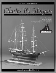
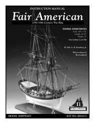
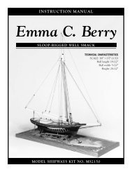
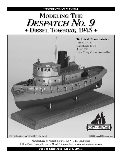
INSTRUCTION MANUALMODELING THEDESPATCH NO. 9✦ DIESEL TOWBOAT, 1945 ✦Technical CharacteristicsScale: 5/32" = 1 ft.Overall Length: 13-1/2"Beam: 3-3/4"Height: 7" (top of mast to bottom of keel)<strong>Instruction</strong>s prepared by Ben Lankford©2006, Model Shipways, Inc.Manufactured by Model Shipways, Inc. • Hollywood, FloridaSold by Model Expo, a division of Model Shipways, Inc. • www.modelexpo-online.comModel Shipways Kit No. 2011
Before You BeginThe Despatch No. 9 is an interesting model forbeginner and expert alike. This kit contains asolid hull, which has been machine-carvedfrom select, medium-hard, fine-grained basswood.This style hull provides a quick andeasy lesson in the basic shapes and proportionsof hull design and helps to developwoodworking skills. Although the exterior ofthe hull has been carved close to the hull linesas shown on the plans, further carving is necessaryfor reasons of accuracy. (Carving andfinishing the hull to its final shape are discussedin the instructions.)Constructing the Despatch No. 9 model alsowill provide you with the opportunity todevelop some scratch-building techniques.During construction, you may want to substitutesome of the kit fittings with your owncreations. By all means try them, especially ifyou think you can improve the model.If you are a beginner, completing this modelwill prepare you for a more complicatedmodel such as the <strong>Dapper</strong> <strong>Tom</strong>, another solidhull model but a sailing ship with rigging tocontend with, and eventually a model likePride of Baltimore II, which is outfitted witha plank-on-bulkhead hull. In the meantime,happy modeling!Working with the Plans & PartsBefore starting model construction, examinethe kit and study the plans carefully. Familiarizingyourself with the kit will serve twopurposes. First, it will let you determine thatall parts have been supplied as listed. Andsecond, you’ll be surprised at how quicklyhandling the parts allows you to better understandthe kit requirements. Try to visualizehow every part will look on the completedmodel. Also, determine ahead of time whatmust be done first. The instructions will helpyou in this regard, but a thorough knowledgeof the plans at the outset is essential.It is also suggested that all small fittings andhardware be sorted into labeled boxes orcompartments to avoid loss during thebuilding process.Two Plan Sheets and Two Template Sheets areprovided:1. Hull Plan (Sheet 1 of 2)2. Lines Plan and Details (Sheet 2 of 2)3. Hull Templates (Sheet 1of 2 - Profile) onheavy paper stock4. Hull Templates (Sheet 2 of 2 - Stations) onheavy paper stockNote: In the process of updating the plans,several new details were added that reflect thereal boat construction as well as details for themodel construction. The real Despatch wasconstructed of fairly thin steel plates thatwould be too thin for a small scale woodenmodel. So, the model construction is modifiedon some details. The real ship detailsprovided are interesting to know and theyallow you to be creative and possibly modifythe model details provided for the kit designto suit your own approach.In addition to the plans, a set of sketchesappears throughout the instruction manualto further illustrate the various stagesof construction.The Despatch No. 9 kit is manufactured to ascale of 5/32" = 1'0" and matches the plans.Consequently, most of the dimensions can belifted directly from the plans using a “tickstrip”. This is simply a piece of paper (a roll ofcalculator paper tape works very well). Mark adimension from the plan onto the tick stripand transfer it to the model.The Despatch No. 9 kit is supplied withBritannia metal, brass, as well as woodenfittings to eliminate problems in making suchparts from scratch. Because the Britanniametals contain no lead, there are no possiblecorrosion problems. Many of these fittingswill require final finishing before installing onthe model.Before painting the cast-meal fittings, cleanthem up by removing all the mold-joint flash.To do this, use a No. 11 hobby blade to cut theflash, then sand with fine sandpaper. It is alsosuggested that you clean the fittingsthoroughly with warm soapy water beforeapplying primer. Make sure they are rinsedthoroughly and allowed to dry before painting.What You’ll Need To StartThe following tools and supplies are recommendedfor the construction process.Modelers who have built before may havetheir own favorites. Almost all are availableat www.modelexpo-online.com.A. Knives and Saws1. Hobby knife with No.11 blades2. Fine tooth razor sawB. FilesSet of needle filesC. Sharpening StoneNecessary to keep the tools razor sharpD. Clamps1. A few small C-clamps2. Several wooden clothespins3. Rubber bandsE. Tool SetA small carving tool set or individualhand chisels for shaping the hull.F. Boring Tools1. Set of miniature drills: #60 to #80(you won’t use all the sizes in the set)2. 1/16", 3/32", & 3/16" bits for various3fitting holes3. Pin viseG. Miscellaneous1. Tack hammer2. Tweezers (a few)3. Small fine pointed scissors4. Miniature pliersa. Small roundb. Flat nose5. Bench vise (small)6. Soldering irona. Solderb. FluxNote: soldering is not essential for this particular modelif the kit fittings are used.7. 1/2" or 3/4" masking tape8. Wire cutters (for cutting fine wireand strip metal)H. SandpaperFine and medium grit garnet or aluminumoxide sandpaper (#100 to #220 grit)I. Finishing:1. Paint brushesa. Fine point for detailsb. 1/4" to 1/2" flat square for hullJ. Supplies: (will be covered in detail inthe Painting section and throughout instructions)1. Paints2. Primer3. White or Carpenter’s (yellow)Wood Glue4. Five-minute epoxy5. Cyanoacrylate (Super) GlueNote about glues: White or Carpenter’s yellowwood glue will suffice for most of themodel. Five-minute epoxy provides extrastrength for gluing fittings. Cyanoacrylate(Super) glue, called CA glue for short, suchas Zap is excellent for quick adhesion. Thebest CA glue for most applications is amedium viscosity gap-filling type. Thewatery-thin type is recommended only tofill a narrow crack by capillary action. ForCA glue, you can also purchase a liquidaccelerator such as Zip Kicker. A spray ordrop of the accelerator will instantly curethe glue. This is handy to eliminate clampingparts for long periods of time waitingfor glue to harden.Use CA glue with caution. You can easilyglue your fingers or eyelids together and thefumes can burn your eyes. It would be agood idea to have a bottle of CA debonderon hand. This product will dissolve the glueif you do get it on your skin.
PaintingIt may seem strange to begin an instructionmanual with direction on applying thefinishes to the model. Not so! Much timeand effort can be saved and a more professionalresult can be obtained if the finishingprocess is carried out during construction.Proper timing in application of finishes andthe use of masking tape to define paintededges should eliminate unsightly glue marksand splotchy stained surfaces. In the end,following these general suggestions will beto your advantage.Paint Colors:The color scheme for Despatch No. 9 is asfollows:Hull Above the Waterline - Medium GrayHull Bottom Below Waterline - Dark GreenDecks - Light BrownDeck House, watertight doors, skylight,masts, life ring and air vents - AluminumHouse Border Trimmings (top mouldingon house, engine room skylight), searchlight, horn, grating at stern, inside bulwarks,and ladders) - RedBitts, chocks, cleats, capstan, and towingengine - BlackVentilator - Aluminum with inside ofcowl RedSmoke Stack - Black with White “S”Airport frames, Window frames. andpilot house doors - Dark BrownRunning lights - Light boxes, outside andtop of the light fixture - Red, Aluminuminside. Port light glass - Red, Starboardlight glass - GreenPaint:Use a flat-finish paint. Model Shipways lineof acrylic paints are available in the recommendedcolors. You may also purchase analready assembled Despatch paint kit fromModel Expo at www.modelexpo-online.com.Primer:Use a grey primer (one is provided with theModel Expo Despatch paint kit. The greycolor will highlight sanding scratches andother defects better than white primer. Primeall woodwork to be painted, and prime allmetal fittings. Lightly sand the primeditems. Use a spackling compound such asPic-n-Patch brand to fill any scratches anddefects, then re-prime.Brushes & Procedures:Use good quality soft sable or synthetic hairartist’s brushes. A small pointed brush isgood for details. For the main hull areas, usea 1/4" to 1/2" flat brush.Before painting, clean the model with a tackrag. Apply your paint in smooth and evenstrokes, overlapping them as you go. Thinthe paint enough to eliminate brush strokes,but not run. You will need three or fourcoats of the light colors to cover the greyprimer and maybe only two coats of thedark. Check your finish between coats andsand and add spackle as necessary to get ridof any blemishes.You will be told how to mark the waterlinelocation in Stage A. At this line, and anywhereelse two colors meet, use maskingtape. Electrician’s black plastic tape or any ofthe hobby tapes made of plastic film areideal. They leave a nice edge and are notoverly sticky. Do not use drafting tape unlessit is Chart-pak brand. The edges are somewhatwrinkled and paint may run underthem. A good trick; seal the edge of maskingtape with a clear flat finish and let dry thoroughly.This will really prevent paint fromrunning under the tape.Sanding alone will not shape the hullenough to precisely match the hull lines.Some carving is required, especially at therail, keel, bow, & stern areas.1. Using the TemplatesFor exact carving to hull lines, a template isrequired for the hull profile and each of the12 stations. You will find a template setprinted on heavy stock paper in the kit. Cutthe templates out carefully with a No. 11hobby knife. Do not use scissors! You willwant a nice smooth edge.Option-The profile template can be cut atStation 6 to make fitting easier. Just makesure you have the keel straight and don’tbuild in a knuckle. Likewise, the stationtemplates can be cut at the bulwark. If youdo this, mark the width of the hull at eachstation on top of the bulwark beforehandand carve to these marks.Note: The profile template shows a notchforward and one aft at the keel and stem.These notches are where the heavy stem pipeand the rudder skeg are glued. The notchescan be added as you carve the profile shape,but probably better if you wait and file thesenotches in when you are ready to install theSTAGE A: SHAPING THE PRE-CARVED HULLstem pipe and rudder skeg.2. Carving the HullCut a wooden block from scrap to about 3"x 1" x 3/4" thick. Screw the block to thedeck so the model can be held in a benchvise for carving. First, check the accuracy ofthe profile and correct it as necessary, using along sanding block.Next, mark the centerline, rabbet lines(where hull meets keel) and station lines onthe model (Figure A-1). Place the stationmarks on the center of the hull bottom andon top of the rails so the marks won’t becarved off as you work. Also, add thebreadth marks on the rail if you elected theoption noted above.Note: The width from the port to starboardkeel and stem rabbet is 3/32" wide from therail at the bow and all the way back to theend of the keel. You will be fitting a 3/32"wide keel strip to this flat area back to Station10. From Station 10 to the end of the keel iswhere the rudder skeg will be fitted. At thesternpost, carve this area down also to 3/32"wide where the stern post will be fitted.Start carving approximately at Station 6(maximum beam) and progress forward,4then aft, using chisels and gouges to cutaway excess wood. Avoid carving against thegrain by shifting forward or aft of Station 6until you find a spot where you are goingwith the grain. Basswood carves easily, soyou probably won’t have much problem withthe grain.Carve very slowly and take off a little woodat a time. Fit the templates as you go. Carveuntil the template fits reasonably well, thenuse sandpaper to obtain the final shape. Atfirst the templates will not fit very well. Youmust compare the template to the hull andvisually decide where to remove wood. Cut alittle off, then re-check the template.Finally, draw a few horizontal pencil lines(like waterlines) and the vertical station lineson the hull. Use these to visually check theshape of the hull. Hold the hull at variousangles, and look to see if the pencil lines arefair (even). If you have any unfairness, dipsor bump, they can usually be found with thisvisual check. You can also use a stiff stick ofwood, about 3/32" square, and lay it on thehull at various locations. Dips in the hullwill show up under the stick.
3. Carving the BulwarksMake yourself a temporary cradle to securethe hull while carving. This cradle also willserve to hold the model for most of theremaining work. Make the cradle so themodel sits in it with its waterline parallelto the baseboard and table. The tops of thecradle should be below the waterline.Later, when you are ready to paint, attacha pencil on top of a wooden block andslide it along the table to mark the locationof the waterline.The machine-carved hull has bulwarksthicker than scale so they won’t break whileinside the kit box. The upper surface is cutto the underside of the cap rail. After youcarve the outside of the hull, the bulwarkswill be thinner. If more than 1/16" thick itwill be necessary to carve the inside of thebulwarks. This is the most difficult part sowork slowly as you carve (Figure A-2). Aftercarving, sand the surfaces smooth. If youhappen to have or want to buy a poweredrotary tool like a Dremel, there are manycutters available to quickly reduce the bulwarkthickness.Note that bulwark brackets go onto theinboard side of the bulwarks. The bracketsshould be 1/32" wide at the top and 5/32"at the bottom. Together with the bulwark,the brackets must fit under the cap railwhich is only 3/32" wide. If the bracketswill not fit, sand the inside of the bulwark alittle more at the top. You can then taperthe inside down to the deck without reducingthe thickness at the deck. You won’treally see that the bottom is thicker thanthe top. Of course, you could use a widercap rail but don’t get it too wide or the scalewill not look proper. Figure A-3 is a crosssection thru the bulwark.Note: As noted earlier, the bulwarks for themodel have been modified from the realboat design somewhat. On the real boat thecap rail and bulwark are constructed from1/4" to 3/8" thick steel plate. At our modelscale these would be paper thin and toofragile for a wooden model. The real boatdetails and the model modifications areshown on the plans.Carving the Bulwark Around the Stern -The bulwark around the stern slopes forwardat a rather large angle. However, onthe real boat, the inboard side is plated inway of the grating platform which covers arudder control quadrant. Carve the insideof the bulwark in this area so the bulwark isvertical (Figure A-4).4. Deckhouse CarvingThe deckhouse construction will be discussedin Stage B.FIG. A-1 MARKING THE HULLWIDTHAT RAIL3/32"RABBET3/32"WOOD TO BECUT AWAYRAILFIG. A-2 CARVING BULWARKSUSE GOUGEFIRSTFIG. A-3 BULWARKCROSS-SECTIONCAP RAILCARVEDBULWARKBRACKET53/32"CLMARK CENTERLINEMARK STATIONSON TOP OF RAILSMOOTHWITHCHISELMARK RABBET LINESMARKSTATIONLINESFITTEMPLATESSUGGEST USINGTHIN METAL SHEETTO PROTECT DECKWHILE CARVINGFIG. A-4 STERN CARVING INBOARDFRONT GRATINGSUPPORT BEAMCUT VERTICALTHIN BULWARKDECKCL
STAGE B: COMPLETING THE BASIC HULL STRUCTURES1. Installing the Keel & StemLike the bulwarks, the model keel is modifiedfrom the real boat as can be seen on theplans. The model keel is 1/16" deep x 3/32"wide basswood. Fit it from Station 10 forwardup to the heavier pipe stem piecewhich starts just below the waterline. For thecurved portion of the keel, steam bend thestrip or cut it out of a wider sheet of 3/32"thick wood.On the real boat the heavy stem is a roundpipe. It is actually fitted over the keel barwhich goes up to the deck. If you have notdone so yet, cut or sand in the notch for thestem, 1/32" deep. For the heavy stem, addeither a 1/8" diameter dowel. Or a 1/8"square basswood strip. For the square, sandthe forward side round and sand the backedges down to the hull. Use wood filler asnecessary to smooth out the joint betweenthe stem and hull (Figure B-1).2. Installing the Sternpost, PropShaft Tube Fairing, & PropellerThe sternpost is a 3/32" thick laser-cut woodpart. This is actually part of large forging atthe stern of the real boat that includes thestern tube. Glue this part to the hull. If it isnot the same width as the hull you havecarved from Stage A, sand the hull flush withthe laser-cut part, or if necessary add woodfiller on the hull so the two will fair. Next,add the shaft tube fairings on both sides. Cutthese from basswood. Shape the inboardsides to the hull shape. The outer facesshould be parallel to the hull’s centerline. Onthe real boat this is just a hump in the hullplating that covers the stern tube whichwould protrude thru the hull if not covered.Install the propeller. The prop has a shaftpiece that should fit in the slot in the lasercutsternpost . You may need to shorten theshaft on the prop, or drill a hole at the slotdeeper into the hull (Figure B-2).3. Installing the Rudder Skeg& RudderAs noted in Paragraph 1 above, the keel wasinstalled forward of station 10. Aft of Station10 you will add the 3/32" thick laser-cut ruddersupport skeg which extends beyond thehull. If you have not yet carved the notch forthe skeg, do so now. The bottom of the skegshould be in line with the bottom of the keel.Drill a hole in the hull for the upper end ofthe rudder stock. At the end of the laser-cutskeg (part 1), add the laser-cut block (part 2)which has a hole for the lower end of therudder stock. Round the outer edges of theskeg per the plan.The rudder is a Britannia casting with thestock already molded in. Fit the upper endin the hole in the hull, then in the skeg, andfinally glue the skeg to the hull. You willFIG. B-1 KEEL & STEMNOTCHFOR STEMFIG. B-2 STERNPOST, FAIRING& PROPLASER-CUTPARTPROP CASTINGFIG. B-4 BULWARK DETAILSCHOCK CASTING3/32" x 1/6" KEELBACK TO STA. 106SHAPETO HULLFAIRINGKEELNOTCH FOR SKEGHAWSE PIPELIP CASTINGTYPICALBRACKETUSING1/8" SQUAREROUND EDGESCUT & ADDWOOD FILLERFOR CURVEDBOTTOM ENDFIG. B-3 RUDDER SKEG& RUDDERRUDDER CASTING,CUT-OFF SHAFTTO FIT HOLELASER-CUTSKEGPART 2ROUNDEDGEQUARTER BITTCASTINGTYPICALSTIFFENERADD WOOD FILLERUSING DOWELCAP RAILLASER-CUTSKEGPART 1
FIG. B-5 PIPE FENDERSHALF-ROUNDCHAFING PIPESCLFIG. B-6 UPPER DECK & PILOT HOUSE TOPLASER-CUTUPPER DECKLASER-CUTPILOT HOUSE TOPSHAPE THEVISORSCUT FROM SHEET,ROUND OUTER EDGE1/8" HALF-ROUNDneed to cut off the bottom of the ruddershaft as it is too long to fit the hole in theskeg. Sounds complicated in words, butFigure B-3 will make it clear as mud.4. Cutting Out & Detailingthe Freeing PortsLayout the freeing ports in pencil first, thendrill several holes in the ports and file or sawout the port. The ports have vertical roundbars. Use brass wire or pins included in thekit for the bars. Installing the wire or pin is atricky task, so it is probably easier to drillholes down thru the top of the bulwark andinsert the wires or pins thru the holes. Cutthe heads off if pins are used.5. Installing Bulwark Brackets,Stiffeners, Cap Rail, Quarter Bitts,Chocks, & Hawse Pipe LipsBefore installing the cap rail, add the fourquarter bitts (Britannia castings - 2 eachside). Cut holes in the bulwark, one eachside, the shape of the bulwark chock castingsand glue them in place. Drill holes in thebulwark and add the Hawse pipe lip castings.The bulwark brackets and stiffenersshould be installed next. The bracket locationsare shown on the bulwark inboardprofile on the plan sheet 2 and the plan alsoshows details for the brackets as fitted on thereal boat as well as for the model. For themodel, the brackets are to be cut from 1/32"thick basswood. On the real boat, there is a1-1/2" diameter pipe welded to the inboardedge of the bracket plate, but that would bea little tedious for this scale model. Betweenthe brackets there are up to three equallyspaced flat bar stiffeners. For the model,use 1/32" square basswood to represent thestiffeners (Figure B-4).Finally, add the cap rail which is 1/32" x3/32" basswood. At the bow and stern wherethe rail curves quite a bit, cut the rail fromthe 1/32" basswood sheet in the kit. Fromjust aft of the aft quarter bitts, there is anotherrail on top of the cap rail going aroundthe stern. This is apparently a chafing rail fortowing lines. Use another 1/32" thick rail forthis piece. At the bow add the small platformbetween the rails.FIG. B-7 CABIN TRUNK, SKYLIGHT, & STACKSKYLIGHT BLOCKWITH 3 AIRPORTS6. Installing the OutboardPipe FendersThe outboard fenders on the real boat arehalf pipes. For the model, pre-sand 1/16" x1/8" wood strips to half-rounds and installthe strips. From Station 12 around the sternthe pipe transitions into a wider plate as canbe seen on the plan view. Cut this area fromthe 1/8" x 1/2" wood strip and sand theouter edge round to match the half roundfender forward. Between the cap rail andpipe fender at the stern install the three halfround chafing pipes. Figure B-5 illustratesthe fender details.EXHAUST RINGS,LASER-CUTSTACK TOP, LASER-CUTSTACK BLOCK(OVAL-SHAPED)CABIN TRUNK BLOCKSTRIP ON SIDES TOCREATE OVERHANGFORWARDPORTION OF VISOR,LASER-CUT7. Constructing the DeckhouseGeneral Makeup of the Deckhouse - Themachine-carved deckhouse consists of themain cabin and the captain’s cabin/pilothouse all in one piece. The top of the pilothouse including the visor is a laser-cut partin 3/32" basswood. The upper deck is alaser-cut part including a portion of the visorfrom the pilot house doors aft. The portionof the visor forward of the doors is also alaser-cut part. The raised area behind thecaptain's cabin (Cabin Trunk), the skylight,and the stack are rectangular wood blocksthat need to be shaped to some degree. Thetop of the stack is a laser-cut part.7
Shaping The Machine-carved Block - Theblock is fairly close to scale except the aft endis about 1/8" too long. You should cut thisoff so the length of the deckhouse blockmatches the plan. However, if you don't, itjust means that the overhanging deck doesnot hang over as much.Test fit the upper deck laser-cut part to theblock. It may be necessary to carve outaround the pilot house and captain's cabinfor it to fit. Next, test fit the forward portionof the visor around the front of the pilothouse. If it does not fit well, sand the frontcurve of the pilot house until it does. Youcould also alter the laser-cut part a bit.Installing The Upper Deck And PilotHouse Top Laser-cut Parts (Figure B-6) -Before gluing the parts in place, cut the taperfor the visors on both the pilot house andmain cabin tops. You could wait until theparts were glued in place but it may be easierto do it beforehand. When you taper thevisor, don't get it so thin at the outer edgethat it could get damaged. Note that thevisor on the real boat is a plate with platebrackets underneath. A detail of the real boatvisor is shown on the plans.Shaping And Installing The Cabin Trunk.Skylight, And Stack (Figure B-7) - Theblock for the cabin trunk must be shaped onthe bottom to fit the deck. First, use a sandingblock and sand the sheer of the deck,You only need to take a little off the forwardend to make it fit. Then, sand in the deckcamber until the block fits flush.The top of the cabin trunk has an overhangFIG. B-8 UPPER DECK BULWARK 1/32" x 1/32"HALF-ROUNDMOULDINGabout 3/32" on each side. Add a piece ofbasswood on each side to form the overhang,then glue the block in place.For the skylight block there is not much todo except check the length and width anddrill holes for the airports.The top of the stack is a laser-cut piece.There are also laser-cut rims for the twoexhaust holes in the top. Glue these rims overthe holes. The stack block must be shapedinto an oval and the shape is just slightlysmaller than the laser-cut top, so use the topas a guide while carving the stack shape.Installing The Bulwark And FashionBracket Pieces (Figure B-8) - Use 1/32"1/32" x 3/32"RAIL1/32"FASHIONBRACKET1/32"BULWARKthick, basswood and cut out the fashion pieceand bulwark at the pilot house. Install thebulwark first and add a 1/32" thick x 3/32"wide cap rail on top. When you get to thepilot house, the outer edge of the rail goes allaround the front of the pilot house as amoulding. Use 1/32" square strip for this.Add the fashion brackets on each side ofthe main cabin supporting the aft upperdeck overhang. Use 1/32" basswood forthis bracket.Most of the remaining details on the deckhousecan be added before the deckhouse isinstalled on the deck. These details are discussedin Stage D so look ahead.Before proceeding with additional work it isbest to mount the hull. This step will helpprevent details from becoming damaged duringhandling and will allow you to make anyalignments that require a true waterline. Propermounting of the hull is very important andwill allow the accurate building and aligningof the remainder of the model. The kit doesnot include any parts for mounting. However,the following suggestions are provided.Mounting Board With Two Pedestals - Acommon mounting for ship models is awooden baseboard with two wooden or brasspedestals. For a homemade board, a nicelooking hardwood such as cherry, walnut, andmaple would be ideal. You can round the topedges of the baseboard, or cut a simple chamfer.If you own a router, or can borrow one,you will be able to cut a nice fancy edge onthe baseboard. Stain the base if necessaryand give it a few coats of varnish or finishlike Minwax.The pedestals could be wood or brass. Onepedestal needs to be longer than the otherbecause you should have the model mountedwith the waterline parallel to the baseboard.STAGE C: MOUNTING THE HULLIf you decide on thistype mounting youshould already havedrilled pilot holes forthe screws as notedearlier. For DespatchNo. 9, the pedestalsshould be locatednear station 4 and 7.If something wentawry and the waterlineis not level, youcan add a brass shimunder one pedestal tocorrect it.Baseboards andpedestals are availablefrom Model Expo(www.modelexpoonline.com).Launching Ways - A second type of mountingthat can be employed is the launchingways, which are most suitable for modelswithout sails. Drilling of the keel is stillrequired to insert rods that anchor the modelto the ways. The launching ways should be8FIG. C-1 LAUNCHING WAY MOUNTINGSIDE SUPPORTSTRUTS1/4" SQUAREWOOD FOR1/8" - 1/4" SCALEMODELSSIDE SUPPORTSTRUTS P/SSUPPORT BLOCKSHEIGHT SET SO MODEL WATERLINEWILL BE PARALLEL TO BASEWATERLINEPARALLEL TO BASEKEEL BLOCKSBASECROSS TIMBERSSUPPORTRAILABOUT1.5 X BEAMOF HULLMETAL RODOR WOODDOWELIN KEELmounted on a baseboard or could be placedin a diorama comprised of boatyard groundactivity.Launching way designs can be found fromphotographs of ships and boats in shipyards.A design for a simple launchway is shown inFig. C-1. You'll adjust the size needed forDespatch No. 9.
1. General NotesDon't forget to file off any flash on Britanniametal fittings, clean the fittings and then primethem with grey primer before final paint.Locate deck fittings and mark their position.This can be done by measuring from stationlines and centerline (tick off from plans).Before permanent installation, paint themaccording to the Despatch No.9 color scheme oryour choice of color.If parts are not painted prior to installation, atleast make sure you have the part sanded andready for painting in place. Use as little glue asnecessary on parts. Watch out for that gluesqueeze-out. It's hard to remove if left to harden.2. Windows, Airports, & DoorsThe window frames are Britannia castings.Glue them in place. Painting first would beadvisable. Since you cannot actually see intothe windows, paint the area inside the framesa semi gloss black.The airports are brass fittings. You will need todrill holes in the deckhouse blocks for insertingthe fittings. A 3/16" bit is required for thelarge airports and 3/32" for the smaller. Afterdrilling the holes, paint the inside black, thenpaint and glue the fittings in place.The deckhouse doors are Britannia castings.Paint first, then glue in place.Note: One port and one starboard watertightdoor at the galley has an airport in the door.Drill and add the airport, then install the door.3. Running Lights, Flagstaff,& MastsPaint, then glue the running lights atop thepilot house. Make the flagstaff and mast fromdowels supplied. Taper the dowels. Glue thethree light castings on the mast. Drill holesand insert the staff and mast.4. Ladders, Upper Deck Railing& Hand RailsThe ladders on each side of the deckhouse,and back of the pilot house are Britannia castings.Cut the castings the correct length asshown on the plans.The rail stanchions on the upper deck are Britanniacastings. Holes are already present inthe laser-cut deck. Glue the stanchions in theholes, then use the brass wire in the kit for therailings.Make the hand rails along the sides of themain cabin from brass wire. Drill holes andinsert the rails. See Figure D-1 for some railingsketches.5. Horn, Searchlight, Bell,Ventilator, & Life RingAll these fittings are Britannia castings. Drillholes as required for the fittings, except thelife ring. This is just glued to the railing onthe back of the upper deck.STAGE D: ADDING THE HULL DETAILSFIG. D-1 RAILING & HAND RAILSSTANCHIONCASTING6. Deckhouse Name Board& LetteringA name board is located on each side of thepilot house bulwark. Cut this from 1/32"thick basswood. Decals are provided for theboat's name on the deckhouse and hull bulwarksand the “S” on the stack.7. Rudder ControlThis paragraph is strictly for the curious.Under the grating at the stern, the originalArmy design has a rudder control quadrant.The quadrant is not shown on the Despatchmodel plans and was evidently not intendedto be put on the model, or possibly there wasa different mechanism installed during constructionwhich was fitted below the deck.The Angels Gate tug at the Los AngelesMaritime Museum had a hydraulic systeminstalled before the Museum received the tugin 1992, so there is no quadrant and cable9WIREWIRE HANDRAIL(TYPICAL)FIG. D-2 RUDDER CONTROL QUADRANTQUADRANTPROTECTIVEPLATE BOX ONTOP OF DECKCHAIN CABLEHAND RAILAT LADDERSHEAVEDECKHOUSESTARBOARD CHAINPORT CHAINabove deck. Was Despatch so fitted during herconstruction? There is no information to sayone way or the other. But just for interest,Figure D-2 shows what the quadrant lookslike on the Army plans.8. Stern GratingThe grating must be assembled using thecherry grating strips in the kit. Assemble justlike an egg crate. But first, cut a pattern fromstiff paper from the front of the grating and tofit the curve of the stern. So as not to wastethe grating strip, cut the pieces just longenough to fit the pattern. Around the curvefit a 1/32" thick strip. Across the front add a1/16" x 1/8" support beam. Glue the assemblyin place (Figure D-3).
9. Bow Chock, Cleats, & ManholesThe bow chock casting is different from thebulwark chocks as it has a bottom flange.Glue it on the rail forward as shown on theplan. The manhole castings require holes tobe drilled in the deck. There are three deckcleat castings. One forward and one port andstarboard near the bulwarks in way of thebulwark chocks.10. Capstan & Towing MachineBoth are Britannia castings. The towingmachine is supplied in six Britannia parts.Assemble before installation. A drawing of themachine and assembly instructions are shownon Plan Sheet 1, and Figure D-4 is a pictorialview. For the platform, cut from basswood,3/16" thick.The Capstan is a single casting. Install at thelocation shown on plan.11. Air VentsThere are two identical castings. Drill holesin the hull deck just forward of the deckhouseand insert the vents. Notice at thetop, the vent barrels at the end of the gooseneckshould be facing outboard, opposite ofeach other.12. Log Fenders & Bow BumperMake the log fenders from wood dowels andwrap the area shown on the plan with blacksewing thread. Paint the dowel a light tan orbrown color. Drill a hole in the top of eachfender for an attachment line. How the linesare attached to the hull is unknown. Youcould put an eyebolt in top of the rail at eachfender or just glue the line on the inside of thebulwark (Figure D-5). Rubber tires were alsoused often on tugs instead of these log fenders.So you have an option.Now the Bow Bumper is something left toyour creative mind. Various types of cheesecloth, wash rags, pieces of real rope cut upand glued together, and the like are just somethoughts. Whatever you come up with, secureit to eyebolts at the rail as shown on the plan.13. AnchorThe Despatch model plans do not show ananchor or any means for handling an anchor.It’s possible no anchor was ever carried sincethe boat was used mostly for towing. However,an anchor has been provided in the kit as afree gift. The original Army tug design has ananchor and a small davit at the bow for handlingthe anchor. There is a socket in the deckport and starboard so the davit can be used oneither side. The Despatch has several configurationdetails different from the originaldesign, probably to accommodate the ownersdesires when built. Since the original ModelShipways plans had no davit, it was probablynot fitted. Another puzzle in the world ofshipbuilding.FIG. D-3 STERN GRATINGSTRIPAROUND EDGELASER-CUTGRATING STRIPSFIG. D-4 TOWING WINCHBITTS CASTINGFAIRLEADERCASTINGWOOD BASE3/16" THICK14. Final TouchesIf you have not done so, installthe deckhouse on the hull. Again,watch out for glue squeeze-out.You may need to add some woodfiller at the house-deck joint.Touch up paint after the filleris sanded.Finally, check to see if any ofthe painted wooden or metalparts were marred or scratchedduring construction andtouch-up as necessary.Congratulations—you’ve doneit! We look forward to helpingyou with your next shipmodeling project.WINCH DRUMCASTINGFIG. D-5LOG FENDERSFRONT SUPPORTBEAMMOTOR & GEARS CASTINGMOTOR UNDERSHAFTFRAME CASTINGBRAKING DEVICECASTINGDOWELWRAP WITHTHREAD10
1. Under Tow: A History of Tugs and Towingby Donal Baird. Vanwell Publishing 2004.BIBLIOGRAPHY2. Tugs: The World’s Hardest Working Boatsby Josh Leventhal. Black Dog & Leventhal, New York 1999. Nothing about Despatch but good look at tug boats in general.3. How to Built First-Rate Ship Models From Kitsby Ben Lankford. Model Expo 2002. Comprehensive reference covers construction methods for solid hull, plank-on-bulkhead, andplank-on-frame kits. The book is profusely illustrated and includes glossary of nautical terms.Note: Some books are available through Model Expo, Inc. www.modelexpo-online.com.Please check current catalog or website for availability.Fine Tools & <strong>Book</strong>s from Model ShipwaysREEVING & SPACING TOOLThis revolutionary new tool makes threading of deadeye assemblies or blocks and tackleseasier, and assures perfect spacing of deadeyes!Two built-in clamps hold deadeyes or blocks securely while you pass the lines through the holes for reeving. Thedifferent slots in the spacing bar let you create even distances between shroud deadeyes and chainplate or blocksof various sizes and shapes. One stationary and one removable spacing bar let you create uniform spacing from1/4" to 1-1/4" in 1/16" increments. Made of molded high-impact plastic, the tool is 7" long and 1-3/4" wide.No. MS107MAKE YOUR OWNSCALE ROPE!COMING SOON!See our websitefor availabilityFAIR-A-FRAME BUILDING SLIPAccommodates virtually any size keel. Makes plank-onbulkheadhull assembly fast and accurate. Adjustablealignment unit straddles base, ensuring that bulkheadsare square to the false keel. Set of ten metal screwsmakes unit fully adjustable in height as well as width. Kitincludes base, laser-cut wooden parts, necessary hardware& instructions. Base: 24" x 4-1/2".No. MS105HOW TO BUILDFIRST-RATESHIP MODELSFROM KITSBy Ben Lankford. Thiscomprehensive referencediscusses how to choose akit, foreign vs. US kits,materials, tools, hull construction,deck furniture,rigging and masting, finishingand display. Covershull construction methodsfor solid hull, plank-onbulkheadandplank-on-frame kits. Profusely illustrated, the bookincludes a glossary of nautical terms, tips on advancedresearch and a list of references for actual ships and shipmodel techniques. 96 pp, softcover.No. MS114LASER-CUT BASSWOOD ROPEWALKPut the master’s touch on your ship models with yourown rope. The Ropewalk from Model Shipways lets youturn ordinary thread into realistic 3-strand scale ropequickly and easily. No complicated mechanics, bobbins,rails or trucks. Our Ropewalk has only two main parts –the gear head and the tail end. It lays up (twists) anythread or cordage into high quality rope in all the necessarylengths and diameter to fully rig your model. TheRopewalk contains all materials needed for assembly:laser cut basswood parts, two diameters of brass tubing,two nylon gears, machine screws & eyes, spacers andretainers, plus clearly written, amply illustrated assemblyand operating instructions.No. MS110ELECTRIC PLANK BENDERBends wooden planking strips with ease. Place yourstrip on the wooden form and heat it by moving theplank bender over it several times. Set includessoldering iron handle with round metal head, plus awood pattern with two different curves.No. MS7205HULL PLANKING CLAMPSLaser cut plywood planking clamps eliminate unsightly holes inyour bulkheads, and hold your planks firmly in place while youglue, drill, measure and taper. Each clamp is 1" square, andincludes a metal screw with wing nut and two 1/16" diameterbrass support rods. Assembly required.No. MX103Set of 6, use with bulkheads less than 3/16" thick.No. MX104Set of 6, use with bulkheads 3/16" or thicker.DELUXE SHIPMODELER’STOOL SETHinged wooden chest contains all the essential knives andtools for building a perfect wooden ship model! Includesthree hobby knives (one each light, medium and heavy duty)with 15 assorted blades, aluminum miter box with saw blade,pointed nose tweezers, stainless steel springconstruction pliers with comfort cushion handles, aluminumawl, 4 assorted gouges, three mini-drills in differentdiameters, plus wooden sanding block and wedge.No. EX44291SAVE TIME & MONEY...ORDER DIRECTLY FROM OUR WEBSITE!www.modelexpo-online.com11
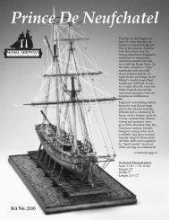
Other Fine Kits fromModel ShipwaysBLUENOSEModel Shipways Kit No. MS2130RATTLESNAKEModel Shipways Kit No. MS2028SULTANAModel Shipways Kit No. MS2016WILLIE L. BENNETTModel Shipways Kit No. MS2032OUR GUARANTEEIf less than delighted, return your purchase within 30 days in original condition.CHARLES MORGANModel Shipways Kit No. MS2140BENJAMIN LATHAMModel Shipways Kit No. MS2109PHANTOMModel Shipways Kit No. MS2027EMMA C. BERRYModel Shipways Kit No. MS2150BEDFORD WHALEBOATModel Shipways Kit No. MS2645USS CONSTITUTIONModel Shipways Kit No. MS2040NIAGARAModel Shipways Kit No. MS2240FLYING FISHModel Shipways Kit No. MS2018PRINCE DE NEUFCHATELModel Shipways Kit No. MS2110MODEL SHIPWAYSSold & distributed by Model Expo, a division of Model Shipways, Inc.3850 N. 29th Terrace, Hollywood, FL 33020Toll-Free 800-222-3876 Monday - Friday 9-5 ET • Fax 800-742-7171SAVE TIME & MONEY...ORDER DIRECTLY FROM OUR WEBSITE!www.modelexpo-online.comPRIDE OF BALTIMORE IIModel Shipways Kit No. MS2120