download benjamin latham instruction manual
download benjamin latham instruction manual
download benjamin latham instruction manual

Create successful ePaper yourself
Turn your PDF publications into a flip-book with our unique Google optimized e-Paper software.
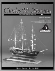
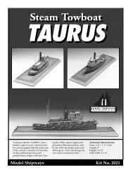
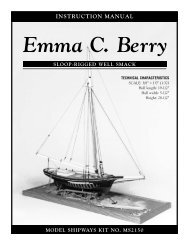
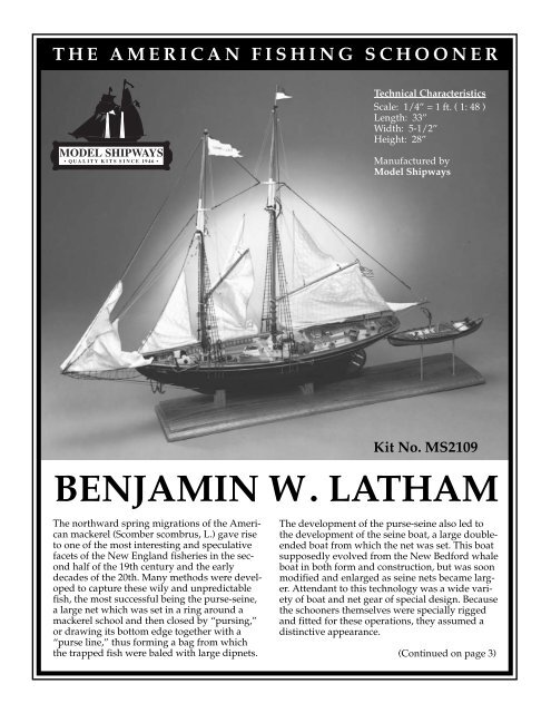
THE AMERICAN FISHING SCHOONER<br />
Technical Characteristics<br />
Scale: 1/4” = 1 ft. ( 1: 48 )<br />
Length: 33”<br />
Width: 5-1/2”<br />
Height: 28”<br />
Manufactured by<br />
Model Shipways<br />
Kit No. MS2109<br />
BENJAMIN W. LATHAM<br />
The northward spring migrations of the American<br />
mackerel (Scomber scombrus, L.) gave rise<br />
to one of the most interesting and speculative<br />
facets of the New England fisheries in the second<br />
half of the 19th century and the early<br />
decades of the 20th. Many methods were developed<br />
to capture these wily and unpredictable<br />
fish, the most successful being the purse-seine,<br />
a large net which was set in a ring around a<br />
mackerel school and then closed by “pursing,”<br />
or drawing its bottom edge together with a<br />
“purse line,” thus forming a bag from which<br />
the trapped fish were baled with large dipnets.<br />
The development of the purse-seine also led to<br />
the development of the seine boat, a large doubleended<br />
boat from which the net was set. This boat<br />
supposedly evolved from the New Bedford whale<br />
boat in both form and construction, but was soon<br />
modified and enlarged as seine nets became larger.<br />
Attendant to this technology was a wide variety<br />
of boat and net gear of special design. Because<br />
the schooners themselves were specially rigged<br />
and fitted for these operations, they assumed a<br />
distinctive appearance.<br />
(Continued on page 3)
Instruction Manual<br />
The American Fishing Schooner<br />
Benjamin W. Latham<br />
Noank Mackerel Seiner, 1902<br />
By Erik A. R. Ronnberg Jr., 1973<br />
Plank-On-Bulkhead Construction and Overall Manual Update<br />
By Ben Lankford, 1994<br />
Model built by Bob Bruetsch<br />
The more you read about the New England fisheries, the more fascinating their history<br />
becomes. Unfortunately, the few substantial reference works available are mostly<br />
out of print, and one must either spend large sums at rare-book shops, or ransack libraries<br />
to get at them. The easier volumes to find are those by Church, Chapelle, and<br />
Story – all excellent reading. Goode’s The Fisheries and Fishery Industries of the United<br />
States is the great work on fishing methods as practiced in the 19th century. It is now<br />
quite rare, but well worth the trouble to locate. Chapelle’s book, The American Fishing<br />
Schooner, is certain to become the standard reference on fishing schooners, their design,<br />
and construction. The beginner would do well to consult Campbell’s The Neophyte<br />
Shipmodeller’s Jackstay and its excellent references. These and other books are<br />
listed in the bibliography at the end of this <strong>manual</strong>.<br />
©Copyright 2005<br />
Model Expo, A Divisions of Model Shipways, Inc.<br />
3850 N 29th Terrace • Hollywood, FL 33020<br />
www.modelexpo-online.com<br />
2
(continued from front cover)<br />
The schooners of the mackerel fleet varied considerably in size at<br />
the end of the 19th century. Prior to 1880, vessels suitable for this<br />
work usually measured 60-80 tons, but with the introduction of<br />
new hull types and incentives to increase the sizes of new<br />
schooners, the early 1900’s saw schooners of 120 tons, and more,<br />
being fitted out for mackerel seining. Auxiliary power was introduced;<br />
nets and boats increased in size; double-crews and gear<br />
were carried in the largest vessels; finally, in the 1920’s, the seine<br />
boats themselves were fitted with engines. This last innovation<br />
was made necessary by the nets, which had become so large they<br />
could not be set and pursed quickly enough under oars alone: if<br />
an “average” seine net measured 203 fathoms long by 21 fathoms<br />
deep in 1880, by 1910 it had grown to 235 by 23 fathoms, and in<br />
the 1920’s, when engine-powered boats became common, the<br />
seine net measured 300 by 24 fathoms.<br />
The schooner Benjamin W. Latham was designed for Captain Henry<br />
Langworthy of Noank, Connecticut, by Thomas F. McManus of<br />
Boston. She was built in the shipyard of Tarr & James at Essex,<br />
Massachusetts, and was launched on October 30, 1902. She was a<br />
very small mackerel seiner for her day, measuring only 72 tons<br />
gross; the same fishery employed vessels nearly twice her tonnage.<br />
Latham’s hull is more like the “spoon-bow” type than anything<br />
else. At the time of her building, this shape was a relatively new<br />
development for fishermen. This design reflects the influence of<br />
B. B. Crowninshield who introduced this hull type to the fishing<br />
fleet two years previously with his first example schooner, Rob<br />
Roy. Also unusual was the knuckle at the forward edge of the<br />
keel, an experiment which few builders seemed inclined to copy<br />
in later vessels. This was a period when owners were anxious to<br />
see their vessels fitted with keels that were straight, not “rockered,”<br />
the latter characteristic having caused many schooners to<br />
slip and fall down on the marine railways when hauled out.<br />
Latham’s keel may have been over-designed for this reason.<br />
Nearly every vessel in the Noank fishing fleet was fitted for mackerel<br />
seining in the early 1900’s, and this undoubtedly was the principle<br />
activity of Benjamin W. Latham. First registered as a sailing<br />
vessel, she seems to have been fitted with a 48-horsepower gasoline<br />
engine sometime in her second or third season. This would<br />
have dictated that her propeller shaft be fitted off-center, either to<br />
port or to starboard as shown on the plans. Since a seiner “bailed<br />
the seine” (removed the fish from the net) to starboard, it would<br />
seem wise to have had the screw to port to avoid fouling the nets.<br />
In keeping with most fishermen, Latham’s career goes mostly undocumented,<br />
except for meager scraps of information yielded reluctantly<br />
by officials of customs and registry documents. She is<br />
known to have had accommodations for a crew of fifteen, and because<br />
of her size, she was a “one-boater” (towed one seine boat).<br />
If the seine boat was a 40-footer, it would always have been<br />
towed astern, since there was no deck room for it aboard the<br />
schooner.<br />
In 1906, Latham was re-registered at New York and operated out<br />
of the Fulton Fish Market. What sort of fishing she did at this time<br />
is not known, although it seems likely that she was converted to<br />
dory trawling. Very likely, she would have been cut down in rig<br />
in the 1920’s, working mainly under power thereafter. What she<br />
looked like in 1939 under Puerto Rican ownership is not known,<br />
nor is the nature of her work. She was lost in 1943 off San Juan,<br />
Puerto Rico.<br />
3
CONSTRUCTION STAGES AND TABLE OF CONTENTS<br />
Brief History Cover, pg 3<br />
Introduction/Credits Pg 2<br />
Before You Begin Pg 5<br />
How to Work With the Plans & Parts Pg 6<br />
What You’ll Need to Start Construction Pg 7<br />
Painting & Staining the Model Pg 8<br />
Stage A: Framing the Plank-On-Bulkhead Hull Pg 10<br />
1. Bending Wood Pg 10<br />
2. Center Keel Assembly Pg 10<br />
3. Installing the Keel-Stem & Sternpost Pg 10<br />
4. Installing the Bulkheads Pg 11<br />
5. Installing the Transom Pg 12<br />
6. Covering the Mast Slots Pg 12<br />
7. Drilling the Rudder Stock Hole Pg 12<br />
8. Installing Horn Timber Cheeks Pg 13<br />
9. Installing the Planksheer Pg 13<br />
10. Installing the Hawse Timbers Pg 13<br />
Stage B: Planking the Plank-On-Bulkhead Hull Pg 14<br />
1. Getting Started Pg 14<br />
2. Planking Battens & Belts Pg 14<br />
3. Planking Butts Pg 14<br />
4. Spiling Pg 15<br />
5. Fastening the Planks Pg 15<br />
6. Planking the Outer Hull Pg 15<br />
7. Plank Variations within a Belt Pg 17<br />
8. Planking the Transom Pg 17<br />
9. Planking the Bulwarks Pg 17<br />
10. Planking the Deck Pg 17<br />
Stage C: Completing the Basic Hull Structure Pg 19<br />
1. Correcting & Sanding Pg 19<br />
2. Natural Wood/Double-Planking Option Pg 19<br />
Stage D: Mounting the Hull Pg 19<br />
1. Mounting Board with Two Pedestals Pg 19<br />
2. Launching Ways Pg 19<br />
Stage E: Adding the Hull Details Pg 20<br />
1. Timberheads (or Bulwark Stanchions) Pg 20<br />
2. Main Rail Pg 20<br />
3. Rail Moldings Pg 20<br />
4. Buffalo Chock Pg 20<br />
5. Monkey Rails Pg 20<br />
6. Main Pinrails Pg 21<br />
7. Boom Jiber Box Pg 21<br />
8. Scuppers Pg 21<br />
9. Rudder Pg 21<br />
10.<br />
11.<br />
12.<br />
13.<br />
14.<br />
15.<br />
Cleats & Snatch Cleats Pg 21<br />
Bowsprit Pg 22<br />
Hawse Pipes Pg 22<br />
Capstans Pg 22<br />
Skid Battens Pg 22<br />
Deck & Rail Fittings Pg 22<br />
Stage F: Mast & Spar Construction Pg 24<br />
1. General Information Pg 24<br />
2. The Importance of Scale Pg 24<br />
3. Tapering Masts & Spars Pg 24<br />
4. Curved Spars Pg 24<br />
5. Lower Mast Fittings Pg 25<br />
6. Topmast Fittings Pg 27<br />
7. Stepping the Masts Pg 27<br />
8. Gaffs & Booms Pg 28<br />
9. Jaws & Goosenecks Pg 28<br />
10. Ironwork Pg 29<br />
Stage G: General Rigging Information Pg 31<br />
1. Cordage Pg 31<br />
2. Treating the Lines Pg 31<br />
3. Differentiating Between the Lines Pg 31<br />
4. Using Beeswax Pg 32<br />
5. Sails: To-be or Not To-be Pg 32<br />
6. Making the Sails Pg 32<br />
7. Rigging the Model With Sails Pg 33<br />
8. Rigging the Model Without Sails Pg 34<br />
9. Flags Pg 34<br />
10.<br />
11.<br />
Rigging & Block Sizes for Actual Vessel Pg 34<br />
Rigging & Block Diameter Conversion Table Pg 34<br />
Stage H: Standing Rigging Pg 35<br />
1. Chainplates Pg 35<br />
2. Rigging the Bowsprit Pg 37<br />
3. Turnbuckles Pg 37<br />
4. Footropes & Manropes Pg 37<br />
5. Fore & Main Shrouds Pg 37<br />
6. Belaying Pin Racks Pg 38<br />
7. Ratlines Pg 38<br />
8. Lantern Boards Pg 38<br />
9. Spring Stay Pg 38<br />
10.<br />
11.<br />
12.<br />
13.<br />
14.<br />
15.<br />
16.<br />
Jumbo Stay Pg 38<br />
Jib Stay Pg 38<br />
Spreader Lifts Pg 38<br />
Fore & Main Topmast Shrouds Pg 38<br />
Main Topmast Stay Pg 38<br />
Pullback Stay Pg 38<br />
Main Boom Footropes Pg 38<br />
Stage I: Running Rigging Pg 40<br />
1. Blocks Pg 40<br />
2. Jumbo, Fore & Main Boom Rigging Pg 40<br />
3. Fore & Main Gaff Rigging Pg 40<br />
4. Head Sail Rigging Pg 42<br />
5. Fore & Main Topsail Rigging Pg 42<br />
6. Staysail Rigging Pg 42<br />
7. Mooring & Other Lines Pg 42<br />
Bibliography Pg 44<br />
Acknowledgments Pg 46<br />
4
BEFORE YOU BEGIN<br />
This kit differs from most in that its large scale (1/4” = 1 ft.)<br />
will permit the model maker to fabricate or “scratch build”<br />
most parts with great accuracy, and in some cases, duplicate<br />
full-size construction or techniques in miniature. For this reason,<br />
the “hows” and “whys” of the vessel’s building and operation<br />
will be explained in greater detail than is otherwise customary.<br />
The novice who attempts this kit should accept this challenge<br />
to the full limits of his or her abilities. Aspects of construction<br />
which may possibly seem too difficult or superfluous to the beginner<br />
will be mentioned as such in that particular discussion.<br />
While the modeling progresses, you will see where you may<br />
want to substitute some of the kit fittings with your own creations.<br />
By all means try them, especially if you think you can<br />
improve the model. The worst that can happen is a little lost<br />
time. But, the experience gained will be most valuable for future<br />
projects. For further reading on modeling techniques refer<br />
to the Bibliography at the back of this <strong>manual</strong>.<br />
Please note that while all of the necessary materials for a beautiful<br />
model have been provided, some detailing work has been<br />
left to the imagination of the individual modeler. For instance,<br />
fishing nets can be made from darkened or stained cheesecloth;<br />
knives and hatches from scrap wood and metal; fish cleaning<br />
trays from scrapwood; and so on. Also, the kit will contain the<br />
minimal number of rigging and block sizes needed for completing<br />
the model. You may want to buy other rigging line or<br />
scratch build blocks to make the model as close to scale as possible.<br />
The detailing possibilities are endless and to provide for<br />
all of them with individual parts would result in a kit far too<br />
pricey for most modelers.<br />
Assuming a modeler works with reasonable skills about 20<br />
hours per week as a hobby, the Benjamin W. Latham model<br />
should take about 5 months to complete (roughly 400 hours).<br />
The most time-consuming tasks will be planking the hull and<br />
completing the masts and rigging. Of course, the time will be<br />
extended if any scratch-built items are substituted. But, don’t<br />
let time govern your progress. The best approach for the beginner,<br />
and experienced modeler alike, is to tackle the job as a series<br />
of small projects which are conveniently laid out for you in<br />
stages. So, don’t look too far ahead, or you may become discouraged.<br />
Assume each small project is an end unto itself and<br />
work on it until it is correct. You will ultimately do a better job<br />
on that particular part, and the overall completed model will<br />
approach perfection.<br />
Beginners, no doubt, will have some problems, especially if<br />
this is the first modeling attempt. The important thing, however,<br />
is to learn from making mistakes. Seek help from more experienced<br />
modelers or the excellent reference material that is<br />
available to you. And regardless of how the model is turning<br />
out, finish it completely. Improvement takes experience; it cannot<br />
be gained with half-completed models. It would be advisable<br />
to follow the <strong>instruction</strong>s in sequence until you gain the<br />
experience to work up your own procedures. Have fun with<br />
the project and think about how nice it will look on display<br />
when it is completed. Good Luck!<br />
5
HOW TO WORK WITH THE PLANS AND PARTS<br />
Before starting model construction, examine the kit and study<br />
the plans carefully. Familiarizing yourself with the kit will<br />
serve two purposes. First, it will let you determine that all<br />
parts have been supplied as listed. And second, you’ll be surprised<br />
at just how quickly handling the parts allows you to better<br />
understand the kit requirements. Try to visualize how<br />
every part will look on the completed model. Also, determine<br />
ahead of time what must be done first. The <strong>instruction</strong>s will<br />
help you in this regard, but a thorough knowledge of the plans<br />
at the outset is essential.<br />
It is suggested that small fittings and hardware be sorted into<br />
labeled containers to avoid loss during building.<br />
1. The Plans<br />
The Latham model kit contains the following 1972-73 plans:<br />
1) Hull & Lines – Plan Sheet 1 of 4<br />
2) Rigging – Plan Sheet 2 of 4<br />
3) Hull, Mast & Fitting Details – Plan Sheet 3 of 4<br />
4) Seine Boat & Purse Seine (rev. 1981) – Plan Sheet 4 of 4<br />
... and the following 1993 plans:<br />
5) Plank-on-Bulkhead Hull Construction – Sheet 1 of 2<br />
6) Plank-on-Bulkhead Hull Construction – Sheet 2 of 2<br />
Many sketches throughout this <strong>manual</strong> further illustrate the<br />
various stages of construction.<br />
The Benjamin W. Latham kit is manufactured to a scale of 1/4”<br />
= 1 ft. Each plan sheet is drawn to the exact scale that the<br />
model is to be built, except for the rigging plan and some details<br />
which have been enlarged for clarity. Therefore, most dimensions<br />
can be lifted directly off the plans by using a set of<br />
draftsman dividers or by using a “tick” strip, which is simply a<br />
piece of paper used to “pick up” the dimensions (a roll of calculator<br />
tape works very well). Lay your paper strip down on<br />
the plan and carefully mark each dimension to be transferred<br />
with a sharp pencil. Then “lift” these measurements by placing<br />
the strip down on the wood or item to be made to scale and<br />
transferring them. You should also obtain a 1/4-inch-to-thefoot<br />
architect’s scale, since all dimensions on the plans are full<br />
ship sizes.<br />
An outline that lists rigging and block diameters for the Latham<br />
is on page 34, along with a Diameter Conversion Table for converting<br />
the full ship rigging and block sizes to 1/4-inch scale.<br />
The table provides a formula for converting diameters to 1/4”<br />
scale. Several conversions have already been calculated for<br />
standard diameters.<br />
Try to maintain the scale size when modeling. As scales get<br />
smaller, the tendency is to build on the heavy side, possibly<br />
from concern about breaking small parts. Models look best,<br />
however, if built to exact scale and even to thinner-than-scale,<br />
which should be the case for a rigging line if the exact size is<br />
unavailable.<br />
2. Making Allowances Along the Way<br />
Try to be exact when following the plans, but use common<br />
sense along the way. You may need to make adjustments or<br />
allow for small differences in how your model is shaping up:<br />
perhaps your mast has too much rake (the angle at which it<br />
sits). When lines go to belaying points they should not drape<br />
over parts or conflict with other lines. If necessary, move a belaying<br />
point or a fairlead block. In other words, put yourself on<br />
the schooner and use your judgement. That is how the early<br />
ship riggers worked!<br />
3. Understanding the Hull Lines<br />
Beginners may not be familiar with hull lines. They are shown<br />
on the Hull & Lines plan 1 of 4. The buttock lines (they are the<br />
vertical lines on the body plan and shown as curved lines on<br />
the profile view) are simply vertical longitudinal sections taken<br />
through the hull. The waterlines, or half-breadths, are horizontal<br />
planes, and the section lines numbered 1 to 22 are vertical<br />
transverse sections. All of these lines define the hull shape and<br />
are used by the draftsman to fair (create regular even curves)<br />
the hull form. With the plank-on-bulkhead construction, the<br />
laser cut bulkheads define the hull form. These are based on<br />
the hull lines, but are made smaller to allow for the thickness<br />
created by adding the planks.<br />
4. Cast-Metal Fittings<br />
The Benjamin W. Latham kit is supplied with Britannia metal,<br />
brass, as well as wooden fittings to eliminate problems in making<br />
such parts from scratch. The Britannia metals are a great<br />
improvement over the white metal that was used in some older<br />
kits. Unlike pewter, Britannia does not contain lead, so there<br />
are no possible corrosion problems. Many of these fittings,<br />
however, will require final finishing before they are suitable<br />
for installing on the model.<br />
Before painting the cast-metal fittings, clean them up by removing<br />
all the mold-joint flash. To do this, use a No. 11 hobby<br />
blade to cut the flash, then sand with fine sandpaper. It is also<br />
suggested that you clean the fittings thoroughly with warm<br />
soapy water before applying primer. Make sure they are rinsed<br />
thoroughly and allowed to dry before painting.<br />
5. Soldering & Working with Brass<br />
Some fittings for the Latham model, such as mast bands, must<br />
be made from brass (see figure 1a). Therefore, a certain amount<br />
of metal working and soldering will be required. Brass strips<br />
are included in the kit. The brass sheet can be cut with a small<br />
pair of tin snips or heavy scissors. Heavier brass will require<br />
the use of a jeweler’s saw. After cutting, all edges should be<br />
smoothed with needle files and fine wet-or-dry sandpaper.<br />
When cutting slivers from the brass sheet, you may notice that<br />
shears tend to bend the sheet sideways, as well as curl the<br />
piece. To straighten the edges in both directions, grip with a<br />
pair of small pliers.<br />
Drilling holes in brass can be accomplished using small drills and<br />
a pin vise, which is a slow process. A Dremel Moto-Tool mounted<br />
on a Dremel drill press is ideal. This tool is worth the cost.<br />
Prior to drilling, use a small centerpunch to start; otherwise, these<br />
small drills tend to wander. Lubricate with a light oil and drill<br />
very slowly to avoid breakage. When using the Dremel, clamp<br />
the pieces in place or hold them down with a stick of wood. The<br />
brass will be very hot, so keep your fingers off!<br />
Soft Soldering: The key here is to keep all brass parts clean.<br />
Use a solvent, or lightly sand, or both. Keep your fingers off to<br />
avoid grease spots. Soldering is easy if care is taken to properly<br />
set up your work area first. Use jigs or other holding devices,<br />
so the parts do not move around. Soldering can be done with a<br />
small torch or pencil soldering iron. First, add flux to the joint,<br />
just enough to do the job. The solder will flow where the flux is<br />
applied. Next, heat the joint.<br />
This sequence is important. The larger the parts, the longer it<br />
will take to heat the brass before the solder will flow. If you get<br />
too much solder on the joint, file it off with needle files. You’ll<br />
want the joint to look like the real thing, not a big glob of fillets.<br />
6
Silver Solder: If extra strength is desired, and also to<br />
avoid the lead in softer solder, silver solder can be used.<br />
A propane torch is a must, as the melting point of silver<br />
solder is much higher. Clean the metal and apply the flux<br />
(liquid silver solder flux is better than the borax type). Cut<br />
a very small piece of solder and lay it next to the joint.<br />
This is necessary because, unlike soft solder, silver solder<br />
will not break away from the roll. It tends to ball up on<br />
the end. Next, heat the joint and solder it together. When<br />
the correct temperature is reached the solder will jump<br />
into the joint––job completed! Be careful to remove the<br />
heat as soon as possible, because the brass also will be<br />
near its melting point.<br />
Figure 1a illustrates how to make mast bands, eyebolts<br />
and rings. Rings can be soldered after they are used on<br />
the model, or not soldered at all, unless there is some<br />
strain on the ring from rigging.<br />
FIG. 1a - Making Mast Bands, Eyebolts and Rings<br />
MAST BANDS<br />
Flux/solder<br />
all joints<br />
Real ship<br />
EYEBOLTS<br />
After soldering,<br />
drill, cut and file<br />
to shape<br />
Pins to hold<br />
parts in place<br />
Form around drill or rod<br />
Solder<br />
Cut off as required<br />
Wood jaws in vise<br />
Form around<br />
dowel or drill<br />
Cut from<br />
sheet brass<br />
WHAT YOU’LL NEED TO START CONSTRUCTION<br />
The following tools and supplies are recommended for the<br />
construction process. Modelers who have built before may have<br />
their own favorites.<br />
A. Knives & Saws<br />
1. Hobby knife with No. 11 blades<br />
2. Coping saw (or jeweler’s saw frame) and fine blades<br />
3. Razor saw<br />
B. Files – Set of needle files<br />
C. Carving Tools – Small chisel for carving center keel rabbet<br />
D. Sharpening Stone – Necessary to keep the tools razor sharp<br />
E. Clamps<br />
1. A few small C-clamps<br />
2. Several wooden clothespins<br />
3. Rubber bands<br />
F. Wire Cutters & Tin Snips<br />
For cutting fine wire & chain; for cutting brass sheet<br />
G. Boring Tools<br />
1. Set of miniature drills: #60 to #80<br />
2. A pin vise<br />
3. Larger bits: 1/16”, 3/32”, and 1/8”<br />
H. Miscellaneous<br />
1. Tack hammer<br />
2. Tweezers (a few)<br />
3. Small fine pointed scissors<br />
4. Miniature pliers<br />
a. small round for forming rings and eyes<br />
b. flat nose (with serrated jaws)<br />
5. Draftsman’s dividers<br />
6. Proportional dividers<br />
7. Bench vise (small) with own base for moving around<br />
8. Soldering iron with 1/8” diameter tip and/or propane torch<br />
a. solder<br />
b. flux<br />
9. Sewing thread (for seizings & lanyards; other rigging in kit)<br />
a. black<br />
10.<br />
11.<br />
b. beige<br />
Beeswax (for treating rigging lines)<br />
1/2” or 3/4” masking tape<br />
I. Sandpaper – Fine and medium grit garnet or aluminum oxide<br />
sandpaper (#100 to #220 grit)<br />
J. Finishing: – Paint brushes<br />
1. Fine point for details<br />
2. 1/4” to 1/2” flat square for hull<br />
K. Supplies: – (will be covered in detail in the Painting &<br />
Staining section and throughout <strong>instruction</strong>s.)<br />
1. Paints<br />
2. Primer<br />
3. Stains/varnish<br />
4. White or Carpenter’s (yellow) wood glue<br />
5. Five-minute epoxy<br />
6. Super glue<br />
L. Cotton or linen cloth: (fine weave) for sails, if added<br />
M. Plastic: Plastic sheet or glass for windows, skylights<br />
Wrap wire<br />
around rod<br />
Saw or cut with<br />
hobby knife<br />
RINGS<br />
Bend in<br />
line – solder<br />
Note about Glues: White or Carpenter’s yellow wood glue will<br />
suffice for most of the model. Five-minute epoxy provides extra<br />
strength for gluing fittings. Cyanoacrylate (Super) glue such as Jet,<br />
can be used for quick adhesion and is ideal for dabbing onto a<br />
rigging seizing to hold it in place. The best cyanoacrylate glue for<br />
most applications is a medium viscosity gap-filling type. The<br />
watery-thin type is recommended to fill a narrow crack by<br />
capillary action and for quick setting of hull planking.<br />
7
8<br />
PAINTING & STAINING THE MODEL<br />
It may seem strange to begin an <strong>instruction</strong> <strong>manual</strong> with directions<br />
on applying the finishes to the model. Not so! Much time<br />
and effort can be saved, and a more professional result can be<br />
obtained, if the finishing process is carried out during construction.<br />
Painting of various small parts, masts and spars<br />
should be accomplished before they are installed on the model.<br />
Painting sequence must be a well thought out procedure, otherwise<br />
you may have difficulty as you proceed with assembly.<br />
For example, it is easier to paint a deckhouse or hatch coaming<br />
before it is glued to the deck. Put the parts aside until they are<br />
ready to be installed. Proper timing in application of finishes<br />
and the use of masking tape to define painted edges should<br />
eliminate unsightly glue marks and splotchy stained surfaces.<br />
In the end, following these general suggestions will be to your<br />
advantage.<br />
1. Preliminaries<br />
Rub down all external surfaces with 220-grit dry sandpaper<br />
and wipe off all dust thoroughly. Give all unprimed surfaces<br />
two coats of primer and already-primed surfaces one more<br />
coat. A very light sanding is recommended after the last coat of<br />
primer, but don’t sand down to bare wood, or the water will<br />
raise the grain and make a terrible mess. With clean hands, a<br />
soft brush, and a clean, soft rag or tack rag, gently dust and<br />
wipe off the hull.<br />
Choosing paint: Consider carefully the kind of paint you will<br />
use to paint your model and the methods of application that<br />
suit you best. Is the paint that you have chosen compatible<br />
with the primer previously applied, or does it blister, crinkle,<br />
or turn to “alligator hide” Better find out! Prime a test block of<br />
wood with the same primers used on the model. When dry,<br />
apply a coat of the brand of paint you have chosen. If the two<br />
don’t “fight” as described above, you may consider it safe to<br />
proceed.<br />
For hand brushing, use a flat-finish paint. Glossy finishes are<br />
not desirable. A satin finish will give the most satisfactory results,<br />
but the undercoat paint should be dead flat. Use model<br />
paints such as the Historic Marine Colors made by Model<br />
Shipways and sold at the Model Expo website: www.modelexpo-online.com.<br />
Are you ready for a real top quality paint job Although slightly<br />
expensive, an airbrush is well worth the investment. Model Expo<br />
sells a very affordable airbrush at www.modelexpo-online.com.<br />
Airbrushes are easy to use, work well with all the paints mentioned,<br />
and do an exceptional job. The air brush throws a pattern<br />
only about 1/2” wide, but obviously, you would still need a<br />
large work space such as a house workshop or isolated room.<br />
Whether you prefer to paint by brush or airbrush, try Model<br />
Shipways paints. These paints are a very fine and versatile line<br />
of ready-mixed water based colors. The colors were specially<br />
developed to emulate the paints used by historic ships. They<br />
are subdued in tones and their properties make both spraying<br />
and brushing techniques easy to master.<br />
Masking off surfaces: It can be very tricky to mask off the surfaces<br />
you don’t want to paint. Some brands of masking tape<br />
are absolutely no good because they allow paint to bleed under<br />
them, so be selective. For masking off fine stripes or lines, such<br />
as the cove line, it is best to use drafting tape, such as the Chart<br />
Pak brand. It is available in widths as fine as 1/32” and 1/64.”<br />
This tape has very good adhesion and will not bleed when applied<br />
firmly. You may also use black plastic electrician’s tape.<br />
Spray Painting: Spraying techniques work best with fast-drying<br />
lacquers. You will find many brands of paint available in<br />
aerosol cans which can give quite good results. Test them on a<br />
wood block as previously described before using them on the<br />
model.<br />
Brush painting: Painting with fine, soft-bristle brushes is probably<br />
best for the beginner. And many highly skilled modelmakers<br />
prefer the brushed-on technique because a brushed<br />
surface, with its fine imperfections, imparts a more life-like appearance<br />
to the model.<br />
Choosing Brushes: Brushes must be very soft and of the highest<br />
quality. Artist grade sable or synthetics are the best. They<br />
should be a littler wider for painting the surface. A too narrow<br />
brush will cause excessive streaking of the finish.<br />
Brushing Technique: When applying paint or stain with a<br />
brush, lay down one thin coat in a single stroke, then coat the<br />
adjacent areas with single strokes. Never make strokes over<br />
fresh paint, or you will tear up the surface. Let the paint dry to<br />
a hard finish before applying a second coat.<br />
Scribing the Waterline: One method of scribing is to level the<br />
hull (mount it so the waterline is parallel to the bench top) and<br />
mark the waterline using a height gauge and a sharp scriber<br />
point (see figure 1b). It is then a matter of painting the bottom<br />
and topside colors precisely to this mark, with or without the<br />
aid of masking tape. The scribe line acts somewhat as a barrier<br />
to paint transgressions, but a steady hand is needed for this operation.<br />
A second method is to spray or brush on the bottom color,<br />
guessing roughly where the waterline will lie and deliberately<br />
painting beyond this arbitrary boundary. The waterline is then<br />
scribed on this overlapping coat of bottom paint and the topside<br />
coat is painted down to the line, covering previous excesses.<br />
Masking tape can be used as a substitute for shaky hands<br />
when painting to the line.<br />
2. Color Scheme<br />
By the early 1900’s, the era had long passed when a fishing<br />
schooner, to quote Chapelle, was “dolled up like the little blue<br />
wagon.” Then, black hulls, grey decks and white superstructures<br />
were the most common color scheme. There were a few<br />
variations, however, and always the chance for a little “gold<br />
leaf and tinsel.”<br />
Hull: The bottom of a schooner very likely had a coat or two<br />
of Tarr & Wonson’s copper paint, then a deep reddish brown.<br />
The topsides were black (add a drop or two of red or umber to<br />
soften intensity) with gilt scrollwork and cove moldings (these<br />
were sometimes yellow, depending on the budget).<br />
It may be wise to paint the cove molding prior to painting the<br />
topsides black. Whether yellow or gold suits your fancy, brush<br />
the paint into the molding (or where the molding should be, if<br />
you omitted it) and allow it to dry thoroughly. Mask over the<br />
cove with 1/32” drafting tape (1/64” is more to scale but tricky<br />
to handle) and press it down gently, using a piece of metal rod<br />
or some similar burnishing tool. Paint over the topsides with<br />
black and remove the tape gently as soon afterward as possible,<br />
peeling at an acute angle to the surface.<br />
Tops & Inboard Sides of Main & Monkey Rails: paint white;<br />
outboard edges should be black.<br />
Bulwarks (Inboard): paint white from rails to decking.<br />
Structures ranging from Bitts to Trunk Cabin: usually painted<br />
all same color: white (or any color that suits you, as captain of<br />
your ship)<br />
Hatch Covers: color of the deck.
Grub (or Great) Beam: often painted white for visibility at<br />
night.<br />
Deck: could be light grey, although some vessels’ decks were<br />
painted Pea Green. Sometimes great circles were swept around<br />
the quarter bitts, at the grub beam, and abreast the foremast.<br />
The color used for the deck was then painted within the radii<br />
(see perspectives drawings on sheet 3 or 4––these are the dark<br />
areas shown on the deck around fiferails, windlass, and along<br />
the waterways).<br />
Waterways: Outside the previously mentioned circles, the waterway<br />
color was painted (this could be white to match the bulwarks,<br />
or a deep prussian blue, which was then quite popular).<br />
In painting the waterways, the caulking line between it and the<br />
deck plank was rigidly followed, even where planks were<br />
nibbed, giving a sawtooth effect along some stretches. Beyond<br />
the arcs of the circles, this did not matter.<br />
Ironwork: was generally black, but sometimes a benign soul<br />
would paint the hawse pipe linings and lips a bright red. The<br />
diaphragm pumps were similarly treated; sometimes they<br />
were a bright red all over; other times they would be black<br />
with only the insides of the bowls and spouts painted red.<br />
Anchors: may be painted black or left a red-lead color, but<br />
their stocks were tarred a glossy dark brown when the tar was<br />
fresh. The anchor chain sat in a rusty heap in the chain box and<br />
may be “antiqued” accordingly on the model.<br />
Windlass Barrel: often had its ironwork blacked. The barrel<br />
inside the riding bitts was oiled or black-varnished, making it<br />
very dark and somewhat glossy. The windlass heads, however,<br />
were often painted white, ironwork and all. In later years,<br />
many windlass barrels were completely painted, usually white.<br />
Hub, Rim & Spokes of Stoddart Steering Wheel: could be<br />
painted grey or white, the mahogany spokes would have been<br />
oiled and their brass caps polished bright.<br />
Bowsprit: may be black or white inboard, and black outboard,<br />
with the iron bands black and the pole white. All gaffs and<br />
booms should be salmon-buff with white tips.<br />
Masts: The lower masts were painted white from the deck to<br />
the boom saddle or the gooseneck; the mastheads were often<br />
white, but some vessels, including Latham, had buff mastheads<br />
with black ironwork. The tips of the mastheads, which protruded<br />
above the caps, were often white-leaded. The topmasts at the<br />
doublings were the color of the lower mast heads; their poles<br />
were generally white. All blocks, regardless of location, would<br />
have been painted the same color as the spars: white or buff.<br />
The hoists of both lower masts and topmasts, over which the<br />
gaffs and mast hoops traveled, were “slushed” or coated with a<br />
mixture of tallow and grease. This allowed gaffs and hoops to<br />
slide up and down with a minimum of friction. The color was a<br />
greyish-umber which darkened when its greasy substance<br />
caught dirt and grime.<br />
Seine Boat: was usually painted white with copper anti-fouling<br />
paint below the waterline. Its inboard works should be all<br />
grey or white.<br />
Gunwales & Gunwale Strakes: were generally a bright yellow,<br />
set off by a red stripe along the lower side.<br />
Dory: any shade of buff, grey or green with light grey inboard.<br />
Oars: oiled natural, but inevitably turned a weathered grey.<br />
Lanterns: Port lantern board is red and the starboard is green.<br />
FIG. 1b – Scribing the Waterline<br />
Is the model perfectly level<br />
Pencil<br />
or scriber<br />
Wood Block<br />
9
STAGE A<br />
FRAMING THE PLANK-ON-BULKHEAD HULL<br />
1. Bending Wood<br />
Building a P-O-B hull requires some wood bending and twisting<br />
of the wood parts which must remain in the desired position<br />
so as not to put too much stress on glue joints and fasteners.<br />
Following are three different methods of bending and<br />
shaping wood:<br />
Steam Bending: This is done by holding the wood piece that<br />
you want to bend over a kettle of steaming water and then<br />
bending it. The wood must be held in the bent position until it<br />
cools. It should remain nearly in that position, but may spring<br />
back slightly.<br />
Soaking: Another method is to soak the wood piece in warm<br />
water for several hours. Try adding a little household ammonia<br />
to the water. This speeds up the soaking process and makes the<br />
wood fibers slippery so the wood is easily bent. After soaking<br />
the wood, shape it to the desired position, using a form. Let it<br />
remain there until it has dried completely.<br />
Hot Iron Bending: You may also bend wood quickly over a<br />
soldering iron, but don’t let it get too hot. It is also possible to<br />
purchase model plank bending irons commercially.<br />
2. Center Keel Assembly<br />
The first step in constructing the hull is to assemble the four<br />
halves of the laser-cut center keel pieces. First, use a sharp pencil<br />
and mark the bulkhead locations below the slots and the<br />
WL-6 reference line. Mark on both sides of each center keel<br />
piece. Be especially critical in locating the reference line. Measure<br />
from several points, taking them from the plans. This reference<br />
line is a key to proper alignment. Next, glue the two 1/8”<br />
laser cut parts that make up keel piece No. 1 together with<br />
white glue and place a weight on the unit until it dries. Make<br />
sure that the pieces are accurately aligned. Repeat the process<br />
with the two 1/8” pieces that make up keel piece No. 2.<br />
Place the two parts, 1 and 2, over a sheet of wax paper or plastic<br />
wrap, on a flat building board or table. Glue the joint with<br />
white or carpenter’s wood glue. Use a steel or aluminum<br />
straight edge to align the WL-6 reference line. Place a weight<br />
on each piece to hold it down while the glue dries. Let the glue<br />
dry at least overnight, preferably 24 hours (see figure 1c).<br />
Next, cut the rabbet in the center keel. The bearding line is the<br />
intersection of the center keel and the inside face of the hull<br />
planks. After the center keel is ready, mark the bearding line<br />
on both sides. The bearding line appears along the sternpost<br />
and the keel-stem. Measure from the P-O-B plans. The plans<br />
show a real ship rabbet for the planks and a model option that<br />
is easier to do. Using a chisel, start the rabbet cut at the bearding<br />
line and cut toward the edge of the center keel. When the<br />
planking is installed, the planks will lie flush on the cut portion<br />
from the bearding line to the rabbet (see figure 2). This completes<br />
the center keel preparation.<br />
3. Installing the Keel-Stem, & Sternpost<br />
The fishing schooner has no real point of change between the<br />
keel and stem, so we will call it a keel-stem. The laser-cut keelstem<br />
(four pieces: glue together as was the Center Keel Assembly)<br />
and sternpost can be added now. Taper the keel-stem according<br />
to hull detail plans before gluing it in place. Dowels<br />
can be used to help align and hold the pieces. Remove any glue<br />
squeeze-out from the rabbet before it sets (see figure 3).<br />
FIG. 1c – Assembling the Two Center Keel Pieces<br />
Building<br />
board or table<br />
Wax paper or<br />
plastic wrap<br />
FIG. 2 – Cutting the Rabbet in the Center Keel<br />
FIG. 3 – Installing the Keel-Stem & Sternpost<br />
Dowel<br />
Keel or<br />
sternpost<br />
FIG. 4 – Shaping the Bulkheads<br />
Bevel<br />
marked<br />
with pencil<br />
Cut with wood grain<br />
Deck bevel<br />
Glue joint<br />
Weight (Approx 2#)<br />
Straight edge<br />
to align WL-6<br />
Hobby knife<br />
Bearding line<br />
Recess for<br />
rudder stock<br />
Center keel<br />
Clean out glue<br />
No! – Get it straight<br />
Chisel<br />
Sternpost<br />
at top<br />
Bevel & cut inboard<br />
side of stanchion<br />
Hobby<br />
knife<br />
10
The top of the sternpost requires a slight recess where the rudder<br />
stock will be located. Carve this in before installing the<br />
sternpost (also see figure 3).<br />
Option: You can add the keel-stem and sternpost before cutting<br />
the rabbet. It makes the rabbet a little more difficult to cut,<br />
but allows an easier installation of the keel-stem because there<br />
is more gluing surface.<br />
FIG. 5 – Fore & Aft Bevel of Stanchions<br />
3/16”bulkhead<br />
1/8”<br />
Sanding<br />
block<br />
4. Installing the Bulkheads<br />
The bulkheads are labeled “A” through “N”. Compare the<br />
laser-cut bulkheads with the plans to determine which is<br />
which and label each bulkhead. Check each bulkhead to make<br />
sure it will slide into the center keel slots. Machine tolerances<br />
during laser cutting may provide a too tight fit. Sand the slots,<br />
if necessary, until the bulkheads slip on. The fit should be<br />
snug, allowing a little tolerance for glue.<br />
On each bulkhead, mark the location of the WL-6 reference line<br />
in pencil. This mark should line up with the WL-6 mark on the<br />
center keel. This alignment will assure that the hull form is accurate<br />
and that each bulkhead is in correct relationship to the<br />
others.<br />
Next, mark the bevels on the bulkheads. Use a tick strip to<br />
transfer the bevel line as shown on the plans, or cut the bulkhead<br />
patterns from the plan and glue them onto the bulkheads.<br />
You may also lay the pattern over the bulkhead and use a pin<br />
prick to locate the bevel. Cut the bevels with a #11 hobby knife<br />
blade (see figure 4).<br />
Some of the bevels are very slight, especially the deck bevels<br />
and the side bevels near amidships. These can be sanded after<br />
the bulkheads are installed, instead of pre-cutting them.<br />
5/32”<br />
FIG. 6 – Installing the Bulkheads<br />
WL-6 must<br />
line up<br />
Tack temporary strip<br />
until glue dries<br />
All of the laser-cut bulkheads extend up to the underside of the<br />
main rail to include a timberhead (bulwark stanchion). Consequently,<br />
bevels must be cut on the inside of the stanchions as<br />
well as on the outside. The bulkheads are located at every third<br />
stanchion. Two additional “fake” stanchions will be added between<br />
the bulkheads after the hull is planked.<br />
In addition to the side bevels, the bulwark stanchion portion of<br />
each bulkhead must be shaped on the fore and aft side. This<br />
can be done with a sanding block (see figure 5). The stanchions<br />
taper slightly and are about 1/8” wide at the rail and 5/32” at<br />
the deck.<br />
Glue the bulkheads in place, making sure that the WL-6 marks<br />
on the bulkheads and the center keel line up. Use a square to<br />
make each bulkhead perpendicular to the center keel. Then<br />
tack a temporary strip to the top of each bulkhead to hold it in<br />
place while the glue dries (see figure 6).<br />
After all bulkheads are in place, tack a temporary batten on<br />
each side of the hull just below the deck (see figure 7). This is a<br />
critical step. Measure the spacing between bulkheads and retack<br />
the battens until the hull is aligned. Even though the center<br />
keel was assembled flat, it could warp out of line. The end<br />
result would be a banana-shaped hull. Check the spacings between<br />
bulkheads, and port against starboard spacings. Check<br />
the hull visually to see if it is properly aligned.<br />
When you are satisfied that the hull is aligned, make sure the<br />
bottom of each bulkhead feathers out and lays precisely on the<br />
bearding line. Trim as necessary to line up. Also, check to see<br />
that the top of each bulkhead at the centerline is flush or slightly<br />
higher than the center keel. Since all alignment is based on<br />
the WL-6 marks, there could be some slight errors. If the center<br />
keel is below the top of the bulkheads, that’s OK. If above, trim<br />
the center keel until it is flush with the bulkheads.<br />
Glue Check 90°<br />
with square<br />
FIG. 7 – Aligning the Bulkheads, using Battens<br />
Check alignment<br />
visually in all directions<br />
Check spacing<br />
Check straightness<br />
of center keel with<br />
straight edge<br />
Tack temporary<br />
batten on hull<br />
11
Next, check the fairness of the hull form and sand in the slight<br />
bevels that were not pre-cut. To do this, use a stiff basswood<br />
batten about 3/32” thick and lay it across the bulkhead edges<br />
and deck in various locations (see figure 8). If not fair, sand the<br />
bevels that stick out, or add shim material if there are dips.<br />
This is an important check. When you start planking, the<br />
planks should lie flat against the bulkheads. No bumps or dips<br />
should occur on the surface. Be mindful here––the functioning<br />
of Murphy’s rule is a possibility. And, manufacturing or assembly<br />
errors can occasionally creep in.<br />
Notice that from the intersection of the sternpost to the transom,<br />
there is no bearding line. This portion of the center keel is<br />
a horn timber on the real ship. The planking will butt against<br />
the timber, so no rabbet cut is necessary. More on this later.<br />
FIG. 8 – Checking the Fairness of the Hull Form<br />
Sand flush with top of<br />
bulkheads if necessary<br />
WL-6<br />
Line up with WL-6<br />
on center keel<br />
Bearding line<br />
5. Installing the Transom<br />
The stern of most ships is difficult to visualize and to construct.<br />
The Benjamin W. Latham has a transom that slopes sharply aft. A<br />
laser-cut transom piece is provided in the kit. This piece represents<br />
the framing timbers of a real ship. It will be covered with<br />
1/16” planks on the outside and 1/32” planks on the inside. But<br />
for now, it is important to install only the laser-cut piece.<br />
Smooth<br />
flow into<br />
rabbit<br />
Trim if necessary to<br />
line up on bearding line<br />
There are various bevels that must be cut on the transom piece<br />
(see the plans and figure 9). The bevels, where the planking<br />
will join, are especially critical. The top bevel will receive the<br />
main rail. The lower (side) bevel receives the hull planking and<br />
is a little tricky to cut. But, if you don’t get it exactly right, it<br />
can be corrected during the planking operation to assure that<br />
the planks land flush on the bevel. After the bevels are cut,<br />
steam bend the transom piece to the required curve (see plans<br />
and figure 10).<br />
Next, slip the transom slot over the center keel in the position<br />
shown on the plans. Make sure the angle is correct by using<br />
scrap wood to create a template for the angle. Glue the transom<br />
to the center keel. Tack a temporary batten on each side from<br />
bulkhead “N” to the transom to hold it in place (see figure 11).<br />
Visually check the transom for alignment, sighting fore and aft,<br />
and from the side. Get it right; a twisted transom looks bad<br />
and creates a problem during the planking process.<br />
6. Covering the Mast Slots<br />
On both sides of the mast slots in the center keel, add the<br />
pieces shown on the P-O-B plan. Cut them from scrap wood.<br />
Glue them securely, because you won’t be able to get to them<br />
after the decking is installed. The mast slots should be slightly<br />
larger than the actual mast. The masts will be wedged in their<br />
holes when installed.<br />
7. Drilling the Rudder Stock Hole<br />
Drill or carve a hole into the center keel directly above the<br />
sternpost as shown on the plans. This hole will receive the rudder<br />
stock. You could omit the hole, cut the stock flush with the<br />
hull, and simply glue the stock to the hull, but the effect is<br />
nicer if a hole is present.<br />
Needs<br />
shim<br />
Needs<br />
trimming<br />
Good<br />
FIG. 9 – Cutting Bevels on the Transom<br />
Top bevel– main rail will<br />
land on this bevel<br />
This bevel should be in line with<br />
the flow of outer hull planking<br />
Heavy batten across several<br />
bulkheads to check fairness<br />
FIG. 10 – Steam Bending the Transom Piece<br />
Clamp<br />
Good<br />
Bottom bevel<br />
at lower end<br />
Bottom bevel at side<br />
Form<br />
Transom<br />
piece<br />
Steam, then bend on form.<br />
Clamp until cool<br />
12
8. Installing Horn Timber Cheeks<br />
From just forward of the hull/sternpost intersection to the<br />
transom, fit a 1/8”-square piece between each bulkhead on<br />
both sides. These “cheek” pieces are located slightly more than<br />
1/16” up from the bottom of the center keel. This area of the<br />
center keel represents a horn timber on a real ship. The cheeks<br />
are for attaching the hull planks at the horn timber. On a real<br />
ship they are bolted to the horn timber (see figure 12).<br />
Notice in the sketch that the bottom of the horn timber from<br />
the sternpost aft is not completely flat, but is a shallow vee<br />
shape. After the planking is installed, this vee can be sanded<br />
in, or you can cut it before planking.<br />
FIG. 11 – Installing the Transom<br />
Transom<br />
Make template for<br />
correct transom angle<br />
Bulkhead “N”<br />
9. Installing the Planksheer<br />
A large ship, such as a clipper, has a separate planksheer, waterway,<br />
and nibbing strake for deck planking. On the fishing<br />
schooner, one piece serves all three functions. The outboard<br />
edge of the planksheer is flush with the outside hull planking,<br />
and the top of the plank is flush with the deck planking. Nibs<br />
are cut into the inboard edge for the deck planks.<br />
On the larger real vessel, the planksheer (or planksheer-waterway<br />
in this case), would be a solid piece with holes cut out for<br />
the bulwark stanchions. With holes cut, the planksheer then<br />
would be slipped over the stanchions. For the model, each<br />
planksheer-waterway section is made up of two pieces. A<br />
laser-cut piece has slots for the stanchions on the outer edge at<br />
each bulkhead. After this piece is installed, a 1/16”-square<br />
strip will be added to the outboard edge to complete the model<br />
planksheer.<br />
FIG. 12 – Installing Horn Timber Cheeks<br />
Center keel<br />
Glue<br />
Temporary batten<br />
on each side<br />
Bulkhead “N”<br />
Bulkhead<br />
“M”<br />
At this time, there are no nibs cut into the inboard edge of the<br />
planksheer. Cut the nibs during the deck planking process in<br />
order to avoid errors.<br />
It may be necessary to file the planksheer slots so they fit snugly<br />
around the stanchions. Also, the aft end of the quarter deck<br />
planksheer is longer than required. Cut the end to fit against<br />
the transom. The forward end of the quarter deck planksheer<br />
should be flush with the front edge of Bulkhead “G.” The fore<br />
deck planksheer should butt against the Bulkhead.<br />
Glue the planksheer pieces in place. The upper outboard edge<br />
of the planksheer pieces should be flush with the outside of<br />
each bulkhead. When in place, add a 1/16”-square basswood<br />
strip on the outside edge (see figure 13). After the hull planking<br />
is completed, the outer edge of the planksheer can be sanded<br />
flush with the hull planks.<br />
10. Installing the Hawse Timbers<br />
The hawse timbers can be a single 1/8”-thick piece at the forward<br />
end as shown on the plans (also look ahead to figure 22a).<br />
Glue the timbers to the top of the planksheer. You can cut the<br />
hawse pipe before you install the timbers if desired. Make sure<br />
you leave space for the bowsprit to pass through at the bow.<br />
Most of the basic framing is now completed and you should be<br />
ready to start planking. Take a moment to look over what you<br />
have done so far. Recheck the fairness of the hull. Making corrections<br />
now will allow the planking process to go smoothly.<br />
Hull<br />
plank<br />
Shallow vee cut<br />
on center keel<br />
FIG. 13 – Installing the Planksheer<br />
Laser cut<br />
planksheer<br />
BEFORE PLANKING<br />
1/8” square<br />
horn timber cheek<br />
Flush here<br />
1/16” square strip<br />
glued to edge<br />
Sand flush with<br />
hull planks<br />
AFTER PLANKING<br />
13
STAGE B<br />
PLANKING THE PLANK-ON-BULKHEAD HULL<br />
1. Getting Started<br />
The planking process is tedious and you should plan on spending<br />
some time doing the job. Work on each plank as a project<br />
unto itself. Rushing will only result in frustration and a poor<br />
result.<br />
Since both sides of the hull will be identical, you can cut two<br />
planks the same shape at once. Fit one plank at a time to each<br />
of the sides. Before starting, place the hull upside down and<br />
secure it in a vise or cradle. It would be ideal to use something<br />
portable that would allow you to rotate the hull easily.<br />
2. Planking Battens & Belts<br />
The model will be easier to plank if you first divide the hull<br />
into a series of “belts.” The belts flow along the hull in smooth<br />
curves. Each belt is designed so the planks lay against the hull<br />
and sweep up at the ends like the deck sheer, lessening the<br />
need for excessive edge bending. Within each belt, the planks<br />
are usually spaced evenly, tapered, and fitted as required.<br />
When selecting a belt width and the number of planks within<br />
each belt, you need to consider how the planks will lay against<br />
the frames and how they will taper. If the planks are too wide,<br />
they will not lay flat on the bulkheads. Also, you will not want<br />
them to taper so much that there is no width left for fasteners.<br />
This would require substituting a larger plank for two to increase<br />
width. Also, in some areas, the planks may get wider<br />
rather than taper. If they get too wide, a stealer plank must be<br />
cut into the plank. While these alterations are acceptable and<br />
are used on many ships, it is best to design the run of planking<br />
to limit the number of such inserts (see figure 14).<br />
To save you the trouble, a planking layout has already been<br />
developed for the Benjamin W. Latham model. The layout is<br />
shown on the P-O-B plans. The arrangement shown is based on<br />
notes in Howard Chapelle’s book, The American Fishing<br />
Schooner (see number 14 of the Bibliography). Generally, the<br />
schooners had about 21 planking strakes per side. The upper<br />
strakes had very little taper forward and aft and no stealers<br />
were used above the waterline. This was done to improve the<br />
appearance of the plank runs.<br />
The Benjamin W. Latham model has been designed with<br />
Chapelle’s observations in mind. The upper belt was kept reasonably<br />
wide forward and aft. Stealers are introduced at the<br />
stern in the lower belt.<br />
3. Planking Butts<br />
Before you start planking, you need to consider the planking<br />
butts. Since the longest length of trees available determined the<br />
cut-lengths of wood, available planking was generally shorter<br />
than the overall lengths of the lifesize vessels. Shipbuilders<br />
generally had to work with planks only 20 or 30<br />
feet long. Some modelers think it is easier to use a<br />
plank length the full length of the model, since fake<br />
butts can be scribed in later or omitted. Granted, this can be<br />
done; it’s really up to the modeler. But, there are some excellent<br />
advantages to using shorter pieces. Since all planks must taper<br />
from midship forward and aft, the use of a short length will<br />
allow the marking of the taper to be quick, and the plank easier<br />
to fasten into place. Also, a short piece can be held down with<br />
one hand. And if you make a mistake, you will have only a<br />
small piece to do over. So, the following is based on the assumption<br />
that you will use the shorter planking lengths.<br />
FIG. 14 – Planking with Stealers<br />
FIG. 15 – Staggering the Planking Butts<br />
FIG. 16 – Spiling<br />
FIG. 17 – Belt Battens<br />
Batten<br />
A<br />
B<br />
C<br />
D<br />
Stealer<br />
PLANKS GETTING TOO WIDE<br />
1. Use compass – run steel point along plank in place<br />
and mark parallel line on new plank with pencil end<br />
Wood – lay along bulkheads<br />
without edge bending<br />
2. Measure width & mark. Draw curve<br />
“G”<br />
Mark locations on<br />
bulkheads with pencil<br />
Parallel<br />
Single plank insert<br />
PLANKS GETTING TOO NARROW<br />
3. Cut out plank<br />
Look for smooth<br />
flow of battens<br />
Bulkhead<br />
Real ship – must be 5’ or more<br />
(model meets rule)<br />
Real ship – must have 3 strakes between butts on same<br />
frame (model meets rule with plank length selected)<br />
Plank already<br />
in place<br />
14
A plank length approximately 6 inches will cover four bulkhead<br />
spaces. This is a comfortable length to handle for this<br />
model. To scale, it is a plank 24 feet long. However, to avoid<br />
having very short pieces at the bow and stern, you may need<br />
to use a longer plank to complete the run.<br />
To follow real ship rules, you should stagger the butts on the<br />
model (see figure 15). The sketch shows a stagger sequence<br />
which is similar to that of real ships. The stagger also applies to<br />
the deck planking. The 6-inch plank works well with the rules.<br />
With this length you can meet the rule for three full plank<br />
widths between butts on a single frame. Had you used a plank<br />
length to cover only three bulkhead spacings, this would not<br />
be possible. Because the butts occur on bulkheads, you would<br />
wind up with only two full planks between the butts.<br />
4. Spiling<br />
On real ships, more so than on models, edge bending is limited.<br />
The wood may be very stiff, so each plank must be cut to<br />
shape. Spiling is the term used for laying out the cuts (see figure<br />
16). It’s simply a matter of transferring curves to a straight<br />
plank, then sawing the plank to shape. For the Benjamin W.<br />
Latham model, the wide planks landing at the sternpost should<br />
be the only strakes you need to spile. For narrow planks, the<br />
basswood strips are flexible enough so they can be edge bent<br />
into place.<br />
5. Fastening the Planks<br />
There are some fancy plank clamps on the market, but they are<br />
more trouble than they are worth. They must be screwed into<br />
the edge of the bulkheads, leaving a big hole to contend with<br />
when doing the next plank. Instead, you can hold the shorter<br />
planks in place, or position them with straight pins. Be careful<br />
not to split the plank when using straight pins. If necessary,<br />
drill a small pilot hole first. Glue each plank to the bulkheads,<br />
and edge glue them together. For the edges, use white or carpenter’s<br />
glue so that setting will not occur too fast. At the bulkheads,<br />
it is good to use thin super glue to quickly secure the<br />
plank in place.<br />
While glue alone will hold the planks, you may wish to use<br />
small brass brads or wooden treenails for additional holding<br />
power, or just for looks. Using fine brass brads, cut off and discard<br />
the heads, then hammer them into place. If treenails are<br />
desired, you can buy them commercially. Better yet, get some<br />
long bamboo skewer sticks, strip off small pieces, then pull<br />
them through a draw plate until you have very small dowels.<br />
Drill holes for the treenails, add a touch of glue and drive them<br />
into place. Treenails are good if you want to add them for each<br />
frame. While there are no frames, only bulkheads, use the bulwark<br />
stanchions for locating where the frames would be.<br />
6. Planking the Outer Hull<br />
Belt Layout: Now the fun begins! From the Hull Planking Layout<br />
drawing, use a tick strip along each bulkhead location and<br />
mark the belt seams. Using a tick strip, transfer the location of<br />
the belt seams onto each bulkhead and mark them with a pencil.<br />
Next, lay the battens (1/16” x 1/8” x model-length basswood<br />
strips) along the marks and temporarily tack them in<br />
place.<br />
The purpose of the battens is to assure an accurate flow of the<br />
belts. Even though the Hull Planking Layout was developed to<br />
provide an accurate flow of belts, errors in drafting and tick<br />
strip marking may occur. The battens were designed to assist<br />
in this regard. With them in place, any errors previously made<br />
can be corrected. Also, you may not like the flow and desire to<br />
change it to suit your own taste.<br />
FIG. 18 – Sloping the Plank Edges<br />
Severe slope–<br />
some rounding of<br />
plank required<br />
BOW AREA<br />
Planksheer<br />
Edge must<br />
be sloped<br />
and fitted<br />
STERN AT TRANSOM<br />
With all the battens in place, visually check their flow. Look at<br />
the model from the side and from the bow and stern. Do the<br />
battens have nice smooth curves Adjust them if necessary (see<br />
figure 17). The sketch shows what they should look like from<br />
the side. When everything seems okay, remark the belt seam<br />
lines on the bulkheads, making sure they are clearly indicated.<br />
You do not want to lose them. You may now remove the battens.<br />
It would be a good idea to leave the middle batten in<br />
place temporarily to help secure the hull so it won’t warp before<br />
it is planked.<br />
Sloping Plank Edges: As you proceed with the planking, you<br />
may need to slope the edges of a particular plank so it butts<br />
flush against the adjacent plank. This is especially true for a<br />
plank adjacent to another member intersecting at an angle. For<br />
example, the first plank below the planksheer at the bow<br />
should butt against the planksheer at an angle. At the stern, the<br />
angle is even more severe. The edges of these planks must be<br />
trimmed so they fit against the planksheer (see figure 18).<br />
To begin with, all the planks on the hull have square edges.<br />
When butted against each other on a round hull form, a small<br />
gap will appear between each plank. Most of the gaps eventually<br />
will be filled with glue, or you may fill them with wood<br />
filler. On a real ship, the gaps are caulked. In fact, the edges of<br />
the planks are often sloped to increase gapping. This measure<br />
assures that the inside of the planks butt against each other,<br />
while on the outside there are sufficient gaps for caulking. If<br />
you want a perfectly smooth hull without the gapping, you<br />
must trim the edge of each plank as you fit it. It’s a lot of work<br />
but your decision.<br />
Laying the Planks in Belt A: Each belt of planking should be<br />
done separately. Consequently, you can start with any belt. For<br />
discussion, let’s start at the top and work down. Belt A has six<br />
planking strakes below the planksheer forward of the deck<br />
step. Aft of the deck step, there is a seventh strake. The extra<br />
strake fills the space caused by the deck step which raises the<br />
planksheer on the quarter deck. The maximum plank width is<br />
at Bulkheads G and H. The planks here should taper both forward<br />
and aft. All the planks can be cut from 1/4” x 1/16”<br />
strips. They should be slightly over 3/16” wide amidships,<br />
tapering to about 1/8” at the bow and 3/32” at the stern. Full<br />
size, the maximum width is about 10 inches.<br />
Use a tick strip and lift the plank widths from the Hull Planking<br />
Layout. If you have changed the locations of the battens,<br />
first mark the position of the seventh aft plank below the<br />
planksheer and in line with the forward planksheer. Then, simply<br />
divide the remaining space into six equal plank widths at<br />
each bulkhead. A set of proportional dividers would help.<br />
Mark these lines on the bulkheads with a pencil. You should<br />
now have a completely marked area for Belt A.<br />
15
FIG. 19 – First Two Strakes in Place<br />
Start<br />
2<br />
“K”<br />
1<br />
“J” “G” “F”<br />
3<br />
“B”<br />
6 5<br />
4<br />
The next step is to cut planks to fit between the marks. Belt A<br />
will not require spiling, so straight tapered planks can be<br />
made. Start at Bulkhead G and install the upper plank under<br />
the quarter deck planksheer. Use two planks, one from Bulkhead<br />
G to K, and another from K to the transom. First, lay a<br />
piece of planking material over the bulkheads. Using a pencil,<br />
mark the lengths at each of the bulkheads. Next, use a set of dividers,<br />
or a tick strip, and lift the plank widths from the marks<br />
on the bulkheads and transfer them to create each plank. Draw<br />
a line through the points and cut the planks. You should now<br />
have tapered planks. Trace these planks to obtain those needed<br />
for the other side of the hull.<br />
Install the planks you’ve just cut on the hull, butting them up<br />
against the planksheer. Where the planking does not fit flush<br />
up against the underside of the planksheer, trim the plank<br />
edges so they do fit. Glue and fasten them into place.<br />
Continue the same process for the next strake below. This time,<br />
the strake will go from the bow to the stern. Stagger the butts<br />
for this strake. Install a plank from Bulkhead F to B, B to the<br />
stem, F to J, and J to the transom. You will have four planks<br />
making up the strake from bow to stern (see figure 19). At the<br />
stern, some planks must be twisted into place. They should be<br />
steam bent if the twists are severe.<br />
FIG. 20a – Planking Nibs at Bow<br />
Typical nibs in lower<br />
bow planking<br />
FIG. 20b – Planks in Belt “C” at Stern<br />
Horn timber cheek<br />
This sharp angle diminishes<br />
rapidly forward of the rabbet<br />
as shown by dotted line<br />
Generally, no nibs<br />
are used above the<br />
design waterline<br />
Move down to the next planking strake and work as before.<br />
Stagger the planking butts, starting at Bulkhead E. Continue<br />
until this strake is complete, then complete the other strakes in<br />
Belt A.<br />
For now, let the aft ends of the planks that rest on the transom<br />
extend just beyond the transom. When you plank the transom,<br />
the transom and hull planks will meet in a miter. More on this<br />
later.<br />
Laying the Planks in Belt B: Belt B is very similar to Belt A in<br />
that it has six planking strakes about the same width. If you<br />
have not removed the temporary batten, do it now. Then you<br />
may start the planking process for Belt B. Remember to stagger<br />
the butts.<br />
Center keel<br />
(horn timber)<br />
Sternpost<br />
Rabbet<br />
Slope edge<br />
of both<br />
planks<br />
This plank<br />
flows to the<br />
horn timber<br />
This plank<br />
flows into the<br />
rabbet<br />
At the stern, a few planks should land on the transom bevel,<br />
and the others should butt against the side of the horn timber<br />
(our center keel) and up against the horn timber cheeks.<br />
At the bow, the planks feather out at the stem rabbet rather<br />
sharply. This is fine for the model, but there is an option. Many<br />
real schooners have nibs in the planking forward (see figure<br />
20a). You can do this if you desire. This also applies to Belts C<br />
and D. See the profile detail on the plans.<br />
Laying the Planks in Belt C: Belt C is also similar to Belt A except<br />
that the planks do not taper as abruptly at the stern. At the<br />
intersection of the horn timber and the sternpost, there should<br />
be an abrupt change. One plank should flow to the horn timber.<br />
The plank below it should flow into the rabbet at the stern-<br />
FIG. 20c – Planks in Belt “D” at Stern<br />
Belt “D” at sternpost<br />
Two stealers in belt “D” only<br />
16
post. These two planks must have their edges sloped so they<br />
meet flush (see figure 20b). Belt C also has some twists, so<br />
steam bend them in place if necessary.<br />
Laying the Planks in Belt D: This belt will contain the garboard<br />
strake (next to the keel) and two other strakes. It also will contain<br />
two stealers in order to reduce the width aft (see figure<br />
20c). All the planks here will be very wide and must be spiled.<br />
You will need to use the wide planking strips provided in the<br />
kit. Also, you will find that in order for these planks to fit in<br />
place, a severe twist must occur. The planks will have to be<br />
steam bent to obtain the right shape.<br />
The stealers could have been placed in Belt C rather than in<br />
Belt D. However, since the tendency of the lower batten is to<br />
naturally flow upward as it goes aft, placing the stealers in the<br />
lower belt is more logical.<br />
7. Plank Variations within a Belt<br />
If you are working within a belt, and have five planks exactly<br />
the same width, and then find that the last plank in the belt<br />
needs to be made slightly wider to complete the belt ... should<br />
you worry Certainly not. No planking job, even on real ships,<br />
is that precise. You are dealing with hand-cut planks. The important<br />
thing is to keep the flow of planks smooth. A variation<br />
in widths is of no great concern.<br />
8. Planking the Transom<br />
For the model, the side hull planks can be extended past the<br />
transom and the transom planks butted into the hull planks or<br />
vice versa. However, on the real ship, the transom plank meets<br />
the hull plank in a miter joint. If you elect to do this, first cut<br />
the ends of the hull plank that you left hanging over, then add<br />
the 1/16” thick transom planks. Cut the miter on each plank,<br />
then glue them into place (see figure 20d). You could also cut<br />
the miter as you add each side plank.<br />
Plank the inside of the transom with 1/32” stock after the deck<br />
planking is installed. Run the transom planks over to the inside<br />
of the bulwark planking.<br />
9. Planking the Bulwarks<br />
The planks between the planksheer and main rail will be in two<br />
thicknesses. From the planksheer to the waist (see location on<br />
plans), use 1/16”-thick material. Above the waist, use 1/32”-<br />
thick material. The bulwark planks are fairly uniform and will<br />
not require any severe tapering forward or aft. First, fit the<br />
1/16” plank. This will need a jog in it at the deck step as shown<br />
on the plans. Next, fit the 1/32” plank. You may let it extend<br />
slightly above the stanchions. Then, trim it flush with their tops.<br />
Scuppers: Later on in these <strong>instruction</strong>s, there is a discussion<br />
on how to cut or otherwise treat the scuppers which go<br />
through the bulwark planking. If you intend to install the scuppers,<br />
now would be a good time to do it. Cut the scuppers in<br />
the edge of the 1/16” planking before it is installed on the<br />
model (see page 21).<br />
The Cove: Another detail that can be done now before the<br />
planking is installed is the cove, a thin hollow molding, located<br />
just below the waist (see figure 20e). This was an important aesthetic<br />
feature of the fishing schooner and accentuated the low<br />
profile and graceful sheer of the hull. The cove can be scribed<br />
with a sharp steel point and straight edge. If you elect not to<br />
scribe in the cove , do not fail to paint it on (generally, it was gilt).<br />
Fashion Piece: At the transom, there is a fashion piece that<br />
must be fitted (see figure 20f). The piece is 1/32” thick, and<br />
should be added over top of the already installed 1/32” plank.<br />
FIG. 20d – Planking the Transom<br />
Hull plank<br />
Transom<br />
plank<br />
REAL SHIP<br />
FIG. 20f – Fitting the Fashion Piece<br />
FIG. 20g – Installing the Great Beam<br />
Notch for<br />
planksheer<br />
BHD “G”<br />
MODEL<br />
OPTIONS<br />
Miter joint<br />
FASHION PIECE<br />
1/32” – fit on top of<br />
1/32” bulwark plank<br />
Quarter deck plank<br />
Planksheer<br />
Main rail<br />
FIG. 20e – The Cove<br />
Waist<br />
Cove<br />
Bulwark<br />
plank<br />
1/32”<br />
bulwark plank<br />
1/16” plank<br />
Great beam 3/32” thick<br />
Scupper<br />
WAIST<br />
Center keel<br />
Fore deck plank<br />
Scrap deck plank support<br />
10. Planking the Deck<br />
The Great Beam & Plank Supports: Before laying any deck<br />
planking, you must install the great beam (also called a Grub<br />
beam by Essex shipwrights) at the deck step. You must also<br />
add some supporting members under the great beam and<br />
under the edge of the planksheer to provide support for the<br />
ends of deck planks. Cut the great beam to the deck camber<br />
curve. The great beam butts against Bulkhead G and projects<br />
1/16” above it. When the quarter deck planks are installed the<br />
planks will be flush with the top of the great beam. Notch the<br />
ends of the great beam to fit over the fore deck planksheer (see<br />
figure 20g). The sketch shows the construction of the great<br />
beam and the supports (see also figure 21).<br />
17
Hatch & Cabin Coamings: Before planking, you must decide<br />
how you want to treat the hatch and cabin coamings. A recommended<br />
approach for doing it the way it was done on the real<br />
ship, is to install all coamings first. You can then plank around<br />
the coamings. On the underside of the coamings, insert some<br />
scrap wood so the deck planking has a support for gluing (see<br />
figure 20h).<br />
Deck Planks: The deck planks should be 1/16” square. The<br />
size may seem small for the scale of this model, but this particular<br />
fishing schooner did have very narrow planks. On earlier<br />
schooners, the planking was much wider. The change was<br />
made to improve the watertightness of the deck.<br />
Prepare the strips by painting one edge black or dark brown.<br />
When the planks are glued together, this will simulate caulking<br />
in the seams. You may also use a brown colored carpenter’s<br />
wood glue on the edges of the planks. When dry, this glue is<br />
dark enough to simulate the caulking.<br />
Thick Pads: There are several thick pads on the deck as shown<br />
on the plans and in the sketches (see figures 21 and 22a). These<br />
can be made of thicker planks that are added as you lay the<br />
deck, or you may add planks over top of the regular deck<br />
planking. It’s your choice.<br />
FIG. 21 – Break at Quarter Deck<br />
FIG. 20h – Hatch & Cabin Coamings<br />
Scrap support for deck<br />
plank and coaming<br />
FIG. 20i – Deck Planking Nib Arrangement<br />
Hatch coaming<br />
Nibs No nibs Nibs No nibs<br />
Nibs<br />
Trunk cabin<br />
Planks parallel<br />
to trunk cabin<br />
Scupper holes<br />
No nibs<br />
Planks parallel<br />
to centerline<br />
Deck plank<br />
Timber head<br />
After hatch<br />
Pump holes<br />
Main mast hole<br />
“PAD”<br />
(thick planking)<br />
MAIN DECK<br />
FIG. 22a – Fore Deck Showing Pads & Hawse Timbers (Cap Rails Omitted)<br />
Waterway<br />
(Timberheads not shown)<br />
Hawse<br />
timbers<br />
Hawse<br />
pipes<br />
Fore mast hole<br />
Companionway<br />
Riding bitt pad<br />
Fore deck pad<br />
Hawse<br />
timber<br />
Hawse<br />
pipe<br />
DECK<br />
“Manger”<br />
Hawse pipe<br />
has flared “lip”<br />
outboard<br />
TOP VIEW<br />
HAWSE TIMBER DETAIL<br />
Great beam<br />
Hawse<br />
timbers<br />
Hawse pipe –<br />
note the<br />
forward slant<br />
Hawse<br />
timbers<br />
Iron<br />
hawse<br />
pipe<br />
“Manger” (wood)<br />
18
Procedure: The fishing schooners had a very unusual deck<br />
planking layout and nibbing arrangement, so follow the plans<br />
carefully (see figure 20i also). Cut the nibs into the edge of the<br />
planksheer as you go.<br />
The fore deck plank should be laid parallel to the centerline.<br />
Start at the centerline and work outboard. Scrape off any glue<br />
squeeze-out before going to the next plank. Planking butts can<br />
be used, like the outer hull, or they may be omitted. On a real<br />
ship, they do not show up as readily as the seams do. You may<br />
also scribe butts after the planking is laid. Since there is no cutting<br />
or curves involved like the hull planking, using long deck<br />
strips is no problem. Use brads or treenails if you like. See Hull<br />
Plank discussion.<br />
The quarter deck should be laid parallel to the trunk cabin<br />
sides. You will end up with nibs at the centerline, as well as<br />
some at the planksheer.<br />
STAGE C<br />
COMPLETING THE BASIC HULL STRUCTURE<br />
1. Correcting & Sanding<br />
After all the planks are installed, look over the entire hull. If<br />
you find seams with starved glue joints, rub some wood glue<br />
in the cracks, and if necessary, add some wood filler. When<br />
seams are filled, sand the entire hull and deck planking until<br />
they are smooth. Addition of the rails and details will be covered<br />
under Stage E.<br />
2. Natural Wood/Double-Planking Option<br />
Most wooden ships have single-thickness planking. The model<br />
of the Benjamin W. Latham is designed with this in mind and is<br />
intended to be painted the colors of the real ship. However,<br />
many modelers are familiar with the European double-planked<br />
kits, or may want to have a natural wood-tone finish on the<br />
hull, which is typical of the Admiralty type models. Also, after<br />
the planking job is completed, some modelers wish to try again<br />
to improve the looks of the job.<br />
If for any reason you desire to double-plank over the basswood<br />
planking, thin wood strips in mahogany, walnut, or some other<br />
types of exotic hardwood can be purchased from Model Expo to<br />
complete the task. For the Latham, you will need 80 strips sized<br />
0.5mm x 5mm x 20 inches long. This amount includes about 20<br />
percent increase for waste and errors.<br />
The strips are only available in up to 5mm widths. Consequently,<br />
you will need to double-up or glue two strips side by<br />
side to arrive at the correct width for some of the wider planks.<br />
The natural wood planks will cover the existing planking, but<br />
you still will have a basswood planksheer, main rails, and<br />
upper rails exposed. Instead of initially using the basswood<br />
for these details, you could make a substitution with the wood<br />
of your choice. You could also cap them with the doubleplanking<br />
strips, or simply stain them to look similar.<br />
When applying the strips, proceed exactly as you did for the<br />
basswood planking process. You may want to work with<br />
longer strips since the basswood planking already defines the<br />
plank shapes. Simply lift dimensions from the hull and cut the<br />
natural wood strips. When completed, sand and finish the hull<br />
with Model Shipways oil or glaze, or tung oil. Finally, add a<br />
coat of wax and then polish it.<br />
MOUNTING THE HULL<br />
STAGE D<br />
Before going on, it is best to mount the hull to prevent details<br />
from becoming damaged during handling. Any alignments<br />
that require a true waterline will be easier to do. Any modeler<br />
may devise his own mounting or purchase mounting kits commercially.<br />
This kit contains two pedestals for use with a mounting<br />
board which you must make or purchase separately. Model<br />
Expo’s Item No. RH4530 30” x 5-1/2” Routed Red Oak base is<br />
ready for staining and highly recommended. It’s size will accommodate<br />
both the Latham schooner and its seine boat. A second<br />
mounting option is the launching ways.<br />
1. Mounting Board with Two Pedestals<br />
If you’ve decided to make your own baseboard to use with the<br />
kit’s two brass pedestals, it must be made long enough to<br />
mount both the schooner and seine boat (a minimum of 30” in<br />
length). With baseboard in hand, round off the top edges or cut<br />
a simple chamfer (taking the edges off or beveling them). If you<br />
own a router, or can borrow one, you will be able to cut a nice<br />
fancy edge on the baseboard. Finish the base with a dark stain<br />
or paint.<br />
Next, drill the pilot holes for the pedestals and support dowels<br />
for the seine boat. Working with a 30” long board, drill the first<br />
pedestal hole 9 inches from the end at width center. Space the<br />
next one 12 inches from the first toward the stern. At the opposite<br />
end of the board drill a first dowel support hole 4 inches<br />
from the end just 2 inches off the port or starboard edge of the<br />
baseboard. Drill the next hole 5 inches from the first toward the<br />
bow. If you have correctly drilled the pilot holes for the pedestals,<br />
the model should sit with the waterline parallel to the<br />
baseboard (see figure 22b). If the balance is off, you can add a<br />
brass shim under one pedestal to correct it. Visually align the<br />
seine boat.<br />
2. Launching Ways<br />
Launching ways are mostly suitable for models without sails.<br />
Make them from scratch or purchase a kit commercially.<br />
Drilling of the keel is still required to apply the rods that anchor<br />
the model to the ways. The launching ways are easily assembled<br />
and should be mounted on a minimal board size of<br />
24” x 6”. (Expanding the size of the board will allow you to create<br />
a mini-diorama comprised of boat yard ground activity.<br />
This would be good for the Latham model so you could lay the<br />
seine boat to rest beside the ways.) Follow the directions supplied<br />
with the ways to achieve the proper waterline level.<br />
Note: It is recommended that either choice mounting piece be<br />
finished before mounting the Hull Assembly into place.<br />
FIG. 22b – Mounting the Hull using Baseboard & Pedestals<br />
Pedestal<br />
Screw<br />
WL<br />
Equal<br />
forward<br />
& aft<br />
Shim to level<br />
19
STAGE E<br />
ADDING THE HULL DETAILS<br />
Before beginning with the details, outline all topside items on<br />
the deck by marking their locations with a pencil. Take all measurements<br />
from the plans using tick strips. Proper locations<br />
should be measured from some firm “bench mark” such as a<br />
mast hole or a station line marked on the deck. Add all equipment<br />
on or near the bulwarks first, before adding those near<br />
the centerline.<br />
1. Timberheads (or Bulwark Stanchions)<br />
These members comprise an extension of the hull frame and<br />
give the bulwarks their form and strength (see figures 23 and<br />
26). During the building of the Plank-On-Bulkhead hull, every<br />
third bulwark stanchion was included as part of the bulkheads.<br />
You now must add two additional “fake” stanchions, and taper<br />
them exactly to the shape used for the bulkheads. Glue them in<br />
place. Scrape off any glue squeeze-out. Let them dry before<br />
proceeding to the main rail.<br />
2. Main Rail<br />
This rail runs the full length of the vessel, capping the bulwarks<br />
and the timberheads (see figures 23 and 24). The railing<br />
along the sides and around the bow and stern must be cut from<br />
the sheet stock and very carefully joined. Simple scarf joints are<br />
recommended, together with careful gluing and pinning. Note<br />
that the outboard side of the rail protrudes beyond the bulwark<br />
planking; likewise, the inboard side covers the timberheads<br />
with a slight margin of overhang.<br />
3. Rail Moldings<br />
The edges on the rails of many fishermen had simple moldings,<br />
usually super-imposed “half-rounds” (see figure 25). If the<br />
model maker wants to contrive scrapers or some other device<br />
to form these, his efforts would be well rewarded. Detailing of<br />
this sort adds much interest and challenge to the work. Otherwise,<br />
especially for the beginner, a neatly sanded rail edge with<br />
neatly rounded corners will suffice.<br />
4. Buffalo Chock<br />
This is a very simple log rail on top of the main rail, port and<br />
starboard, at the bow (see the plans and figure 30). It should<br />
be square or rectangular in cross-section and taper aft slightly.<br />
Taper the rail first, planing and sanding it lightly. Next,<br />
file the ends to their proper shapes. Soak or steam the pieces<br />
and bend them to fit the main rail. Then fasten them down<br />
with glue and pins.<br />
5. Monkey Rails<br />
Fit the monkey board first (see figure 26). This is made from<br />
1/16” x 1/8” for the sides. The section over the stern should be<br />
cut from a 1/8” block. Piece the corners. Over this is placed the<br />
monkey rail which can be made from 1/16” x 1/8” strip-wood<br />
planed down to 3/64” x 1/8”. This rail is made in much the<br />
same way as the main rail. However, steam bending the side<br />
portions may be preferable to cutting them from sheet stock.<br />
Over the monkey rail is placed the monkey log, made from<br />
1/16” x 1/16” strip-wood. Note that part of the port monkey<br />
log is omitted to make room for the seine roller. Follow plan<br />
sheet 1 of 4 closely on this matter.<br />
FIG. 23 – Railing at Main Deck Deck<br />
Main rail<br />
FIG. 24 – Railing Joiner Work<br />
Breast<br />
hook<br />
Quarter<br />
knee<br />
Scarf<br />
Simplfied<br />
scarf for<br />
models<br />
FIG. 25 – Some Common Railing & Superstructure Moldings<br />
CAP RAIL MOLDINGS<br />
2/3<br />
1/3<br />
A. Traditional “hawks bill”<br />
molding (called “dirt catcher”<br />
in the gloucester area.)<br />
1/2<br />
1/2<br />
B. Cruder style of “hawks<br />
bill” molding. Very common<br />
among fishermen.<br />
C. No molding.<br />
Crudest & cheapest.<br />
D.<br />
E.<br />
BOW<br />
Pinrail at<br />
bulwarks<br />
STERN<br />
No inside<br />
molding.<br />
Fife rail showing a<br />
typical stanchion<br />
and an occasionally<br />
used rail molding.<br />
F. HATCH<br />
SIDES<br />
Inside<br />
rabbet<br />
G. TRUNK CABIN<br />
(end view)<br />
Half lap<br />
joints<br />
Coaming<br />
Dovetail<br />
joint<br />
Coaming<br />
Note: on bulwark rails, it was common to use the same<br />
moldings on both inboard and outboard edges, including the<br />
bulwark pin rails. This is not usually the case for the fife rails<br />
at the fore and main masts.<br />
20
6. Main Pinrails<br />
These are simple swellings of the main rail on its inboard sides<br />
abreast of the main mast which hold the belaying (see lower<br />
right of figure 25). Note dimensions and their location on the<br />
hull plan. No alterations to the main rail are necessary for fitting<br />
the belaying pins at the fore shrouds.<br />
7. Boom Jiber Box<br />
This is an extension of the taffrail (main rail at the stern) and<br />
should be blended smoothly with it. Install the support chocks<br />
and prime and paint the area within them (check the color<br />
scheme in the section on Painting and Staining the Model).<br />
Then install the boom buffer hardware (also primed and painted).<br />
With this finished to your satisfaction, glue down the jiber<br />
box top, making sure that the block ring for the main sheet<br />
aligns properly with the opening. Since this detail is now essentially<br />
complete, be sure that you are satisfied with your<br />
workmanship, because these parts will be quite inaccessible<br />
later, if repairs are needed or afterthoughts begin to haunt you.<br />
8. Scuppers<br />
As can be seen on the bulwarks and rigging profiles of the<br />
plans, the bulwarks of the Benjamin W. Latham are pierced with<br />
many scupper holes. These openings on the real ship permitted<br />
rapid drainage of water which frequently found its way over<br />
the lee rail in heavy weather. They measured 1” x 5” but on the<br />
model are mere slits measuring 1/50” high x 1/10” long. One<br />
of the greatest pitfalls encountered in the modeling process is<br />
creating these holes grossly over scale. If you feel confident<br />
that you can drill or punch them out and retain a true-scale effect,<br />
go ahead and try it. Otherwise, a convincing effect can be<br />
produced by making slight indentations in the bulwarks on the<br />
outboard side, using an old small screwdriver that has be<br />
ground down to 1/10” in width and sharpened to a chisel<br />
edge. Scribe lines outboard at main and quarter deck levels and<br />
locate the scuppers so they lay on either or both sides of the<br />
timberheads as shown on the plans. Remember, the holes were<br />
meant to let water out, not three pound mackerels! As noted<br />
earlier in the <strong>instruction</strong>s, you may cut the scuppers before installing<br />
the bulwark planking.<br />
9. Rudder<br />
The rudder is of the plug-stock type and is provided laser-cut<br />
in the kit. It should be securely bolted to the rudder/stern post,<br />
which is a round wooden plug that pivots on the rudder’s true<br />
axis. Fit the stump-ends of the stern post’s upper and lower<br />
parts into blind holes drilled in the center keel. The lower end<br />
should be tapered and fastened neatly to the rudder blade with<br />
glue and pins. Notch the hinge-side of the rudder as shown on<br />
the plans and add the pintles (see figure 27). Mark the corresponding<br />
locations of the gudgeon straps on the stern post and<br />
make, or “fake”, the gudgeons to suit your preference. The<br />
rudder can now be installed, but it is advisable to prime and<br />
paint it, together with the stern post, before final installation.<br />
FIG. 26 – Railing at Quarter Deck<br />
Monkey log<br />
Monkey rail<br />
Monkey board<br />
Main rail<br />
FIG. 27 – Pintles & Gudgeons, Connecting Rudder & Sternpost<br />
A. Actual practice<br />
Iron strap<br />
B. “Faked pintle”<br />
Paper or<br />
shim strap<br />
C. “Faked” hinge<br />
Paper straps<br />
Pin forged<br />
to strap<br />
Gudgeon<br />
“padded out”<br />
FIG. 28 – Fitting the Bowsprit<br />
Gudgeon<br />
(above is<br />
top view)<br />
Pin bent at<br />
slight angle<br />
Paper strap<br />
Samson post mortised<br />
for bowsprit heel<br />
Bowsprit<br />
Eyebolt<br />
Drift pin<br />
Head of stem post should<br />
be fitted so bowsprit beds<br />
snugly on it<br />
10. Cleats & Snatch Cleats<br />
With the outboard woodwork of the hull done, the deck structures<br />
now may be made and fitted. First, finish up the bulwarks<br />
by making the numerous cleats and snatch cleats from<br />
strip-wood leftovers (see plan sheet 3 of 4 at top middle section<br />
and figure 31). Then glue them to the timberheads as shown on<br />
the plans. Follow these locations closely. Next, carefully paint<br />
the bulwarks (white). Apply two or three coats according to directions<br />
on the paint container. Leave no nook or cranny unpainted.<br />
Paint the rails, too. Then drill them with holes for the<br />
belaying pins and eyebolts which will be installed later.<br />
FIG. 29 – Built-up Deck Structures<br />
Forward companionway<br />
(forward side)<br />
Chain box<br />
21
11. Bowsprit<br />
At this point, the bowsprit should be made. See the section on<br />
spar making for various construction methods. Next, make the<br />
samson post and fit it very snugly into the deck. After this is<br />
done, the bowsprit heel socket should be carefully located on<br />
the post’s forward side. Take the post out and mortise the socket<br />
into position. Then cut a tenon into the bowsprit heel. Next,<br />
replace the post and test fit the bowsprit. Check the bowsprit<br />
for the proper steeve (the angle that a bowsprit makes with the<br />
horizon or the keel). If the angle is off, make a new samson<br />
post, correcting the position of the heel socket (see figure 28).<br />
12. Hawse Pipes<br />
Drill out the hawse pipes for the anchor cables and fit the managers<br />
inboard (refer to figure 22a). The hawse pipe lips furnished<br />
in this kit may now be added to the outboard edges of<br />
the hawse holes.<br />
13. Hatches, Forward Companionway,<br />
Trunk Cabin & Wheelbox<br />
If you elected to add the various hatch and cabin coamings<br />
during the deck planking process, you will now need to complete<br />
the hatches and build the wheelbox, companionway, and<br />
trunk cabin for fitting on top of the coamings. If you planked<br />
the entire deck without providing the coamings, you’ll need to<br />
make the complete units and glue them on top of the deck<br />
planking after carefully marking their positions.<br />
This kit provides only strip or sheet wood to construct these<br />
furnishings. Consequently, these items must be built up. Follow<br />
the plans for the various shapes and moldings shown on<br />
the plans (see also figures 21, 25 & 29). As an option, you could<br />
cut the cabin and companionway from solid basswood or pine<br />
blocks onto which you would then add the various moldings.<br />
Use of blocks was common in older Model Shipways kits with<br />
solid wood hulls. Each modeler is pretty much on his own as to<br />
how he wishes to make these deck furnishings. Let ingenuity<br />
and a desire for detail be your guides. For beginners who feel<br />
equal to the task, review earlier paragraphs on moldings and<br />
add these to the hatch coamings and cabin sides.<br />
When the individual items have been completed, prime and<br />
paint them, and then set them aside to dry.<br />
14. Skid Battens<br />
Next, cut pieces of 1/32” x 1/32” strip-wood to specified<br />
lengths and glue them to the decks to serve as skid battens, as<br />
shown on the deck plan. Use the deck structures you have just<br />
made as guides for the precise placing of the battens.<br />
15. Deck & Rail Fittings<br />
Sort out and identify the various castings for the deck and rails.<br />
After assembly, priming and painting, set them in their proper<br />
locations. Drill and socket where necessary (see plans for locations).<br />
The fittings are as follows:<br />
Cat Head: (see figures 30 and 31)<br />
Anchor Catted: (see figure 31)<br />
Windlass: (see figures 32, 33 and 34)<br />
Pump: (see figure 35)<br />
Boom Buffer: (see figure 36)<br />
Steering Wheel: (see figure 37)<br />
Propeller: (see figure 38)<br />
Exhaust Pipe: (see figure 39)<br />
FIG. 30 – Iron Cathead<br />
Buffalo chock<br />
FIG. 33 – Windlass, Aft View<br />
Riding bitt<br />
Ratchet<br />
Whelp (wood)<br />
Pawl<br />
Chain whelp<br />
(iron)<br />
Whelp stud<br />
Windlass head<br />
FIG. 34 – Windlass Pump, Forward View<br />
Pump ratchet<br />
Quadrant<br />
Club-boom<br />
crotch<br />
Samson post<br />
Cleat (wood spacer)<br />
Samson post<br />
Bowsprit<br />
Brake pivot<br />
Windlass brake<br />
(removable)<br />
Rocker<br />
arm<br />
Riding<br />
bitt knee<br />
Pad<br />
Quadrant link<br />
22
FIG. 31 – Anchor Catted<br />
FIG. 32 – Assembling the Windlass & Bitt Support Mechanism<br />
Clasp<br />
(wood)<br />
Rocker arm<br />
(2 castings)<br />
Samson post<br />
(wood)<br />
WINDLASS ASSEMBLY<br />
Buffalo chock omitted<br />
FIG. 35 – Pump Assembly<br />
Cleat<br />
Snatch<br />
cleat<br />
Windlass barrel<br />
(1 casting)<br />
Quadrant<br />
(2 castings)<br />
Rocker arm<br />
(1 casting)<br />
Pivot<br />
(1 casting)<br />
Pump bowl<br />
casting<br />
Plunger<br />
casting<br />
Pump<br />
base<br />
casting<br />
Pump<br />
brake<br />
casting<br />
Make parts<br />
from brass<br />
wire (supplied)<br />
Solder<br />
QUADRANT LINK ASSEMBLY<br />
See plans, sheet 1 for actual dimensions<br />
(assembled soldered)<br />
Pad<br />
Riding bitt<br />
(wood)<br />
Riding<br />
bitt knee<br />
(wood)<br />
Quadrants<br />
Quadrant<br />
links<br />
FIG. 36 – Boom Buffer<br />
Pin<br />
Make<br />
brass<br />
ring<br />
FIG. 37 – Wheel & Wheel Box Assembly<br />
Rudder<br />
post<br />
Steering wheel<br />
(1 casting)<br />
Wheel box sides,<br />
ends, and top are<br />
made of wood<br />
Section<br />
View<br />
Buffer links<br />
(2 castings)<br />
Hook main<br />
sheet block<br />
to ring<br />
Buffer link<br />
(1 casting)<br />
Shaft 1/16” brass rod<br />
Pad (thick plank)<br />
Note: The steering gear housed in the wheel<br />
box is a rather complex device which is best<br />
substituted by the rig shown above.<br />
Open<br />
Open<br />
Rudder post<br />
The wheel shaft is bent 90° at its aft<br />
end and fitted into a hole centered on<br />
the top of the rudderpost<br />
FIG. 38 – Propeller Assembly<br />
SIDE VIEW<br />
FIG. 39 – Exhaust Pipe<br />
Propeller<br />
shaft strut<br />
(1 casting)<br />
Strut<br />
Shaft<br />
Propeller<br />
casting<br />
Jiber box<br />
Propeller shaft-<br />
1/16” brass rod<br />
Propeller casting<br />
Shaft log (wood)<br />
faired to hull bottom<br />
Propeller and shaft<br />
are joined midway<br />
in strut socket<br />
Exhaust pipe casting<br />
Aft end of exhaust<br />
pipe should project<br />
1/16”- 3/32” beyond<br />
transom<br />
23
STAGE F<br />
MAST & SPAR CONSTRUCTION<br />
1. General Information<br />
Carefully study the details of masts and spars which appear on<br />
all four sheets of the kit plans. Sheet 3 of 4 contains details of<br />
the hardware which must not be overlooked. Likewise, the<br />
leads and belaying points for the running rigging must be<br />
given careful attention. When you feel certain that you understand<br />
what goes where (and hopefully why), you should next<br />
take out the dowels supplied in the kit and match them to the<br />
spars of equivalent lengths and diameters as shown in the<br />
plans.<br />
Note that virtually all spars on this vessel are tapered and that<br />
proportions of the tapers differ somewhat:<br />
1) On gaffs and booms, the point of greatest diameter lies<br />
about 1/3 of the spar length from the jaws (or gooseneck).<br />
2) The bowsprit’s maximum diameter is at the knightheads<br />
where it passes through the vessel’s bow.<br />
3) Lower masts are thickest at about deck level and taper upward<br />
to the tops, where there is a more pronounced taper from<br />
crosstrees to caps.<br />
4) Topmasts have very little taper at the doublings where they<br />
overlap the lower masts. Above these, they taper in a fashion<br />
similar to the lower masts, but are surmounted by poles, to<br />
which the trucks and flag halyards are fastened.<br />
2. The Importance of Scale<br />
While the scale of masts is important, the booms and gaffs are<br />
probably the most critical spars to consider in regard to proper<br />
scale. Stubby, fat-ended booms and gaffs stick out like sore<br />
thumbs, giving a model that unprofessional look. Care should<br />
be taken to assure that they are tapered properly and to correct<br />
scale.<br />
3. Tapering Masts & Spars<br />
All spars have a parabolic (curved), not straight taper. Sighting<br />
down the spar, you would find that the sides bulge like the<br />
sides of a barrel, but in a much less distended fashion. The kit<br />
provides either round or slightly tapered birch dowels for<br />
masts and spars, but final tapering to plan dimensions is still<br />
required. A dowel is difficult to taper since it is already round.<br />
The best approach is to slice the dowel from a round shape at<br />
maximum diameter to a square shape at the ends, then to an<br />
eight-sided shape, then sixteen-sided shape. Final rounding is<br />
achieved by sanding. This approach prevents a round dowel<br />
from becoming an oval (see figure 40).<br />
In finishing the tapered dowels, which are generally supplied<br />
too long, cut off the excess from each end so that the point of<br />
maximum diameter lies as indicated in the plans. To cut off<br />
ends, make a nick with a knife at the end mark and roll the<br />
dowel back and forth under the blade until it cuts through. It is<br />
advisable to sand the spars prior to cutting them, otherwise<br />
you may round the ends off excessively, or produce some<br />
strange taper that was never seen on any sailing vessel.<br />
To taper a straight dowel, use a small hobby plane (see figure<br />
35 for planing sequence). The plane blade must be very sharp<br />
and adjusted to remove only a thin curl of wood at a time. The<br />
taper of the lower masts from deck to hounds should be very<br />
slight; from 5/16” at the deck to 9/32” (1/4”+) at the cheeks,<br />
and may be ignored by the novice, but not by the more experienced<br />
modeler. Above the crosstrees, the mast heads should<br />
taper more noticeably, but the “flats,” which accommodate the<br />
cheeks and trestletrees, make planing tricky. It is probably<br />
safer to file the mastheads down to size. Remember that on<br />
fishermen, mastheads are round in section, not square (see figure<br />
41). Mark carefully where the cheeks and trestletrees are to<br />
go, and carefully file “flats” into the sides for them.<br />
4. Curved Spars<br />
If you have been doing your homework and have been eagerly<br />
poring over photographs of fishermen in the books previously<br />
recommended, it should become readily apparent that there<br />
was hardly ever a straight spar on a Gloucester-rigged vessel.<br />
From the day the early riggers went aboard a new vessel to<br />
“dance in her rigging and weave their spell on her,” the masts<br />
would be sprung forward and the bowsprit “hogged down.”<br />
All was done in the interest of keeping the stays “tight as fiddle<br />
strings,” so the vessel would sail well and close to the wind.<br />
The lower masts would always be stepped and wedged with a<br />
slight 2° to 3° rake aft. The lengths of the fore and spring stays<br />
were carefully calculated to be a little short. Then, with the aid<br />
of a special tackle and a large gang pulling at the hauling end,<br />
the masts would be sprung forward, and the stays shackled to<br />
their respective straps or eyes.<br />
A new mast would have had a very slight forward rake which<br />
became more pronounced with the change in seasons as adjustments<br />
were made to keep the stays tight. The topmasts, being<br />
of lighter stuff, were sprung more easily and required more<br />
frequent adjustment; therefore, they usually had a more pronounced<br />
forward curve than the lower masts. After two or<br />
three years, these sticks became so badly warped, they had to<br />
be replaced. The bowsprit was similarly treated, but here turnbuckles<br />
were used to get the necessary tension and resultant<br />
curvature.<br />
Other spars such as the gaffs and booms were not induced to<br />
take unnatural shapes on purpose, but stresses caused by the<br />
sails could warp them (see figure 42). The booms were usually<br />
so heavy and poorly supported when idle, that they sagged<br />
considerably, particularly when resting on the boom crotches.<br />
The previous information is mentioned for the sake of the perfectionists<br />
and the uninformed who may now be looking disconsolately<br />
at a warped dowel, wondering whether he should<br />
attempt to straighten it or replace it. Unless the warpage is really<br />
bad, take advantage of the situation and shape the dowel so<br />
the bend will simulate the condition of the actual spar. This will<br />
spare the rigging on the model from the severe strains imposed<br />
by trying to duplicate the tense rigging of the actual vessel.<br />
It is a source of great pride for the skilled modeler to be able to<br />
produce perfectly straight, symmetrical spars thus representing<br />
a vessel perfectly constructed and fitted out Bristol fashion.<br />
But, we are dealing with a vessel that should be fitted out in<br />
Gloucester fashion––meaning that the end results are expected<br />
to be less than perfect! By nature, the rigs of these early fishermen<br />
flirted precariously with the laws of mechanics. Principles<br />
of rigging predicated spars distorted by high tension. In other<br />
words, a working fisherman with perfectly straight spars probably<br />
never existed. So, if realism is your preference, your<br />
model should carry sprung spars. More follows on this subject.<br />
5. Lower Mast Fittings<br />
After shaping the fore and main masts, mark the forward and<br />
aft sides at both ends where they will be easily readable. Next,<br />
mark the levels of the lower sides of the trestletrees and file<br />
“flats” for these and the cheeks on the port and starboard sides.<br />
24
Now make and fit these members to the mast, securing them<br />
firmly with glue and pins. Allow them to dry firmly.<br />
Meanwhile, fashion the spreaders from 1/16” x 3/32” stripwood,<br />
tapered as directed on Sheet 4 of the plans. Make end<br />
notchings and add any prescribed eyebolts, but do not glue the<br />
spreaders to the trestletrees until the masts are ready to rig. If<br />
installed now, they will surely break.<br />
Bands for the halyards: These may be added now. It was common<br />
practice with Essex-built craft to drive the halyard ringbolts<br />
through the masts and the bands, then secure them with<br />
fore locks (see figure 43). One simple method to simulate this is<br />
to glue a strip of rag paper around the mast, drill a hole<br />
through it and the mast, and drive in a ringbolt, bending it over<br />
at the far side. When painted, the paper band can look very<br />
convincingly like metal. Metal bands can be made as shown in<br />
figure 1a.<br />
Throat halyard cranes: These should be fitted next. But, DO<br />
NOT GLUE the throat halyard cranes in place until after the<br />
spreaders are installed at rigging time. If you wish, make the<br />
heart irons and linkages for the throat halyard blocks, paint<br />
them, hook them to the cranes, and set these assemblies aside<br />
until they are needed (see figure 44).<br />
FIG. 40 – Tapering Masts & Spars<br />
Plane<br />
Spar<br />
Plane in this direction<br />
(Always with the grain)<br />
Make more<br />
strokes at this end<br />
(tapered end)<br />
Plane in this direction<br />
TAPERING A DOWEL<br />
When the taper has been “4-sided”, as shown above, it may then<br />
be “8-sided”, “16-sided”, then rounded with a file, and sanded<br />
smooth. (Dotted lines indicate wood to be removed)<br />
4-sided<br />
8-sided<br />
16-sided<br />
Rounded<br />
FIG. 41 – Lower Mast Head<br />
7/32”<br />
FIG. 42 – Mast & Spar Curvature<br />
Halyard tension<br />
Dashed lines indicate<br />
rake of masts and steeve<br />
of bowsprit prior to<br />
setting up the stays.<br />
Sagging in<br />
boom crotch<br />
Topping lift<br />
Taper is blended to<br />
smooth contours<br />
above spreaders<br />
A<br />
“Flatted”<br />
for cheeks port<br />
& starboard<br />
Level of<br />
trestle trees<br />
Taper is<br />
quite<br />
pronounced<br />
Taper is<br />
slight<br />
A’<br />
This shows with some exageration (but not much!) the degrees<br />
and directions of warpage of spars induced by rigging, sagging,<br />
and tension from running rigging and sails.<br />
FIG. 43 – Mast Head Bands & Eyes<br />
Actual Practice:<br />
ring bolt goes through<br />
band; sets up on forward<br />
side of mast head<br />
Fore-locks<br />
Ring bolt<br />
Section A-A’<br />
9/32”<br />
5/16”<br />
Diameter at deck<br />
Ring<br />
For Models:<br />
wire eyebolt goes through<br />
paper or shim band, is bent<br />
over on forward side<br />
Mast band<br />
Bent over<br />
Eyebolt<br />
Ring<br />
25
FIG. 44 – Throat Halyard Fittings<br />
FORE<br />
MAIN<br />
Iron band<br />
Crane<br />
Iron crane<br />
Spreader<br />
Heart<br />
iron<br />
Iron heart<br />
Iron “gate”<br />
Trestle tree<br />
Cheeks, P &S<br />
Shackles<br />
Upper<br />
halyard<br />
blocks<br />
Block<br />
Topping lift eye<br />
(These views looking forward)<br />
Lower<br />
halyard<br />
blocks<br />
Ring or<br />
spectacle<br />
iron<br />
Ring<br />
Spectacle<br />
iron<br />
Gaff<br />
Gaff jaw<br />
Oak chafe battens<br />
(strips 3/4” x 1-1/2”)<br />
nailed to mast.<br />
Sheet iron was later<br />
used; open seam<br />
on forward side<br />
Iron strap<br />
Topsail sheet<br />
blocks:<br />
P & S (fore)<br />
S. only (main)<br />
Note: vessels 90-120 tons carried two double blocks at the<br />
fore cranes and a triple block at the gaff jaws (fore only),<br />
but this rig may have been more than necessary for a small<br />
vessel like Latham, thus the above substitute<br />
Wooden truck<br />
(“clapper”)<br />
Parrel<br />
FIG. 45 – Mast Caps & Masthead Fittings<br />
Shackle for pullback<br />
stay lanyard<br />
Spring stay<br />
Figure-8 link for<br />
main topmast stay<br />
lanyard (port side)<br />
Topping lift crane<br />
Iron bail<br />
Band below foremast<br />
cap only<br />
Crane<br />
pivot eyes<br />
Split<br />
key<br />
Figure-8 link, P & S<br />
for spreader lifts<br />
Cap<br />
Bail<br />
Round head<br />
thru-bolt<br />
FOREMAST<br />
Jibstay bail<br />
Figure-8 link (outer)<br />
MAIN MAST<br />
END VIEW<br />
Bail (inner)<br />
26
Mast caps: Originally of iron, these are supplied as metal castings<br />
in the kit. But if you prefer to make your own, it is suggested<br />
that you make them of brass strips or short lengths of<br />
tubing, soldered together. You can also drill and file them out<br />
of brass or aluminum flat stock. The caps must be drilled<br />
through to accommodate bolts and links which support the<br />
spreader lifts and also serve as pivots for the bails (supporting<br />
half hoops) used for the stays (see figure 45). In addition, an<br />
eyebolt must be fitted to the aft side of the main cap for the<br />
topping lift crane. A lower crane pivot must also be made and<br />
fitted. All of this construction must be well made. It is desirable<br />
to solder all eyes in the bails for extra strength.<br />
Fore mast: The foresail boom requires that a gooseneck be fitted<br />
to the fore mast. This will allow the fore boom to clear<br />
dories, the seine boat and any other main deck clutter (see figure<br />
46). It can be made of paper strips, pins and eyebolts in a<br />
manner similar to the peak halyard bands.<br />
Main mast: This gets fitted with a wooden saddle. It is furnished<br />
as a casting in the kit, but may be substituted with a<br />
wooden piece of the modeler’s own fabrication, if desired.<br />
6. Topmast Fittings<br />
The hardware for topmasts is quite simple: one band at the<br />
foremast head; two at the main. Brittania castings are provided<br />
for these bands, but not all of the eyes on each band are needed.<br />
Snip off all those that are not called for in the plans. These<br />
may be glued down after the topmasts are in place.<br />
Topmast Heels: These must be “fidded” and wedged into the<br />
trestletrees very carefully. This is a good time to make a trial fit<br />
and install the “gates” for the trestletrees at the same time (see<br />
figure 47).<br />
FIG. 46 – Fore Boom Goose Neck<br />
Shackle and hook for<br />
fore sail tack (hook<br />
points to port)<br />
Swivel pin with split<br />
key on port side<br />
FIG. 47 – Trestle Trees<br />
FORE MAST<br />
Split key<br />
Ears on mast<br />
bands for tightening<br />
bolts, P &S<br />
(TOP VIEW)<br />
Swivel pin<br />
Shackle<br />
outside all<br />
7. Stepping the Masts<br />
Finish up the masts by adding any forgotten eyebolts and<br />
hardware. Fit the spreaders and throat halyard cranes. Then<br />
add the chafe collars to the lower masts (refer back to figure<br />
44). Stain and paint these according to earlier directions. Next,<br />
slide on the mast hoops and mast coats, both of which are supplied<br />
as castings (see figure 48). The masts may now be<br />
stepped into the mast holes and wedged tight with slivers of<br />
wood which should be cut off at deck level. Add a touch of<br />
contact cement around the wedges and slide the mast coats<br />
down until they rest snugly on the deck. You may now proceed<br />
with the standing rigging or go on to the other spars.<br />
Rigging <strong>instruction</strong>s begin in Stage G.<br />
Topmast<br />
heel “gate”<br />
Cheek<br />
Eyebolt, P & S,<br />
for jumbo<br />
halyard blocks<br />
FIG. 48 – Mast Wedges & Coats<br />
Wedges<br />
driven<br />
around<br />
mast<br />
Wedge<br />
Wedges driven<br />
Lead strips<br />
For Model:<br />
use castings<br />
supplied or turn<br />
out of hardwood<br />
Mast hole<br />
Canvas mast<br />
coat (stitched<br />
on aft end)<br />
Wedges driven<br />
below deck level<br />
27
8. Gaffs & Booms<br />
Methods of tapering and shaping these spars are the same as<br />
for the masts. But, you must adapt their lengths and the position<br />
of their fittings to suit the rigging and clear any fixed obstructions.<br />
For example, if you made an error, however slight,<br />
in spacing the fore and main masts so that the gaff and boom<br />
of the foresail strikes the main mast if swung from port to starboard,<br />
you must shorten the gaffs and booms to allow adequate<br />
clearance. Likewise, check to see if the jumbo boom will<br />
clear the fore mast when it is hauled full-back on its gooseneck.<br />
Fittings on booms should coincide with mating deck fittings.<br />
Is the main sheet band on the boom centered over the boom<br />
jiber Check the other booms, too! Anyone can make small<br />
errors of this nature; it happened on full-size vessels, too. But,<br />
if you do not make allowances for these little mistakes now,<br />
your errors will be compounded in later work, making them<br />
far more obvious.<br />
FIG. 49 – Gaff & Boom Jaws<br />
TOP VIEW<br />
Wood grain<br />
ROUGH CUT JAWS<br />
FIG. 50 – Main Boom Jaws<br />
SIDE VIEW<br />
Clapper<br />
Carve, file<br />
and sand<br />
TOP VIEW<br />
Round edges<br />
Sharp<br />
edges<br />
FINAL SHAPED JAWS<br />
TOP VIEW<br />
9. Jaws & Goosenecks<br />
These are the most conspicuous fittings on the masts. So, they<br />
should be strongly and neatly made. Jaws may be rough-cut<br />
and glued to the spars prior to finishing touches (see figure<br />
49). They are perhaps easiest to do on the assembled units.<br />
Small, hinged shoes, or clappers must be set in the jaws of the<br />
gaffs and main boom. The main boom clapper differs from the<br />
other two (see the plans and figure 50).<br />
Boom<br />
jaw<br />
Main tack<br />
eyebolts (2)<br />
Pivot<br />
pin<br />
Parrel<br />
strap<br />
Tack<br />
eyebolts<br />
Clapper<br />
Parrel<br />
(iron bail)<br />
FIG. 51– Bands for the Booms<br />
Clew<br />
of sail<br />
ACTUAL PRACTICE<br />
(scale drawings are on plans)<br />
Hinge<br />
Set up<br />
bolt<br />
Iron bail<br />
Wire link<br />
Iron-plate link<br />
Outhaul band<br />
(jumbo, fore<br />
& main)<br />
Sheet band<br />
(jumbo, fore<br />
& main)<br />
Crotch<br />
tackle band<br />
(main only)<br />
SIMPLIFIED FOR MODELS<br />
(these are suggestions only)<br />
Link<br />
Boom tackle<br />
band<br />
(fore & main)<br />
Two eyebolts<br />
side by side<br />
Wire bail<br />
Wire link<br />
Wire eyebolt<br />
Paper or<br />
shim band<br />
Out haul band<br />
Sheet band<br />
Lill pin, end bent over<br />
Shim or<br />
Wire eyebolt paper band<br />
“pinched”<br />
Eyebolt, P & S<br />
Wire strap at sides<br />
Wire link<br />
Crotch tackle band<br />
Boom tackle band<br />
28
10. Ironwork<br />
Ironwork is somewhat more difficult to make for the gaffs and<br />
booms than for the masts and bowsprit. The bands are smaller,<br />
more complicated, and drilling a thin dowel for the eyebolts<br />
and sheave holes is a tricky job at times (see figure 51 for<br />
the different types of bands required for these spars).<br />
Booms: The fore boom gooseneck has been illustrated in figure<br />
46 and the jumbo boom gooseneck appears in figure 52. If<br />
you wish to fake the ironwork with paper and wire, simplified<br />
assembly methods are shown in figure 51.<br />
Gaffs: The ironwork for the gaffs is not as demanding. Throat<br />
halyard blocks and hardware have been shown in figure 44.<br />
This should be a thoroughly enjoyable project for the modeler<br />
who finds fine metalwork an interesting challenge, which it<br />
should be. The fore peak halyard blocks are fixed to bands on<br />
the gaff (see figure 53a). The main peak halyard blocks run on<br />
wire bridles which are seated in shallow grooves in the gaff<br />
(see figure 53b). These block bridles are discussed in the section<br />
on standing rigging.<br />
The ends of the gaffs are fitted with blocks for the topsail<br />
sheets. The fore has two cheek blocks (important note: the fore<br />
topsail sheets are double!). The main has a single block shackled<br />
to a band. The main gaff also must have a band with an<br />
eye-strap for the flag halyard (see figure 54).<br />
Bowsprit: There is much ironwork to be fitted for this spar<br />
which includes the bobstay irons and gammon irons (See figures<br />
55 and 57). First, fit the wooden jackstays onto both sides<br />
of the bowsprit along its upper outboard edges (see figure 56).<br />
Drill them out for the jib stops (for locations see Rigging Plan<br />
Sheet 2 and upper left corner of sheet 3. Near the end of the<br />
bowsprit is a withe (four eyes) to which the outer bobstay, the<br />
jibstay and the bowsprit guys are shackled (see figure 58). Just<br />
inside of this withe is fitted a brace band (no eyes) which supports<br />
the former by helping to distribute some of the compression<br />
loads. The brace band may be faked with paper, but the<br />
withe might be better made with metal. Or, you can use a brittania<br />
metal casting provided for the purpose.<br />
On the underside of the bowsprit, abaft the bands of the lifesize<br />
Latham was a long plate for the inner bobstay. Passing<br />
through that plate was a heavy metal staple which formed the<br />
bobstay eye. The ends of this staple were headed over clinch<br />
rings on the upper side of the bowsprit (see figure 58). On the<br />
model, the metal plate can be simulated with heavy paper, but<br />
the eye must be very secure. Form a small staple from a common<br />
pin. Next, drill a hole in the bowsprit for it. Then drive<br />
the pin up through the hole and bend the ends over neatly.<br />
Outboard of the bands projects the pole of the bowsprit, from<br />
which the balloon stay is shackled. This pole has a longitudinal<br />
band running its whole length, above and below, and is recessed<br />
into the wood. A strip of rag paper will represent that<br />
fitting nicely. An eyebolt can be driven through the pole and<br />
headed over underneath to accommodate the jibstay.<br />
Seine boat & net booms: The ironwork for these is quite simple<br />
and covered in detail on the seining gear Plan Sheet 4 of 4.<br />
FIG. 52 – Jumbo Boom FIG. 53a – Peak Halyard Straps & Bridles FIG. 53b – Bridle for Main Peak Halyard Blocks<br />
ACTUAL<br />
FOR<br />
MODEL<br />
ACTUAL<br />
(popular at turn of century)<br />
Iron roller or saddle<br />
Knot<br />
Goose neck<br />
FORWARD VIEW<br />
Iron strap<br />
(all fore gaffs and many or most main gaffs)<br />
Splice<br />
Make a fine<br />
groove in gaff<br />
for bridle<br />
FOR<br />
MODEL<br />
FIG. 54 – Gaff Ends<br />
Topsail sheet block<br />
Wood cheek block,<br />
port side<br />
Cheek blocks,<br />
port & starboard<br />
Iron band<br />
or<br />
Double<br />
topsail sheets<br />
Flag<br />
halyard<br />
block<br />
Peak outhaul<br />
Peak outhaul<br />
1. For larger vessels 2. Probally better for Latham<br />
MAIN GAFF<br />
FORE GAFF<br />
29
FIG. 55 – Bobstay Irons<br />
BASIC<br />
INSTALLATION<br />
X-SECTION<br />
Make wire staple;<br />
form eyes at ends<br />
FIG. 56 – Jib Stops<br />
Wood jackstay<br />
Figure-8 knot<br />
Pin<br />
Bobstay link<br />
Wire<br />
link<br />
Bowsprit<br />
Iron straps<br />
Glue on<br />
paper “strap”<br />
Wire<br />
staple<br />
Drill hole & cut<br />
groove in stem post<br />
Paper “strap”<br />
MODIFIED FOR<br />
MODEL WORK<br />
Whipped ends<br />
FIG. 57 – Gammoning<br />
Lill pin,<br />
end bent over<br />
Bolt<br />
Wire eyebolts driven<br />
thru bowsprit<br />
Gammon<br />
strap<br />
Paper strap<br />
Iron<br />
rivets<br />
ACTUAL PRACTICE<br />
Ends recessed<br />
in stem knee &<br />
bent inward<br />
SIMPLIFIED<br />
FIG. 58 – Bowsprit Ends<br />
Jib stay<br />
Man rope<br />
Backing<br />
band<br />
Iron withe<br />
Balloon stay<br />
eyebolt<br />
Inner<br />
bobstay<br />
plate<br />
Inner<br />
bobstay eye<br />
(staple)<br />
Iron withe<br />
Bowsprit<br />
guy<br />
turn buckle<br />
Iron strap<br />
(let in flush)<br />
Bowsprit<br />
Pole<br />
Outer bobstay turnbuckle<br />
Iron strap<br />
Inner bobstay eye<br />
(in recessed plate)<br />
Withe<br />
Backing band<br />
Foot rope<br />
SIDE VIEW<br />
BOTTOM VIEW<br />
30
STAGE G<br />
GENERAL RIGGING & SAILMAKING INFORMATION<br />
Rigging plans are often confusing because of the numerous<br />
lines involved, and the fact that overlapping and concealing of<br />
some of the detail occurs. Every effort, however, has been made<br />
to make the Benjamin W. Latham rigging procedure as clear as<br />
possible. Modelers should have little trouble, if the plans are reviewed<br />
thoroughly and the <strong>instruction</strong>s are followed.<br />
1. Cordage<br />
Standing rigging is black and running rigging is white. The<br />
nylon rigging line supplied in this kit will be adequate for most<br />
modelers. To rig as accurately as possible, however, search out<br />
and buy different line sizes to match the scale of the plans.<br />
Seasoned veterans will probably want to make substitutions,<br />
using linen, which comes in a wider variety of sizes and will<br />
last longer. Rigging diameters, block lengths and a conversion<br />
table are given on page 34.<br />
Generally speaking, when selecting the size of thread for a<br />
given line, it is better to err on the small side. Many beautifully<br />
crafted hulls have lost their look of realism because of a heavy,<br />
clumsy-looking rigging job. Look at photographs of these fishermen<br />
and note how delicate the rigging appears, then strive to<br />
attain the same visual effect.<br />
The use of wire for standing rigging: By Benjamin W. Latham’s<br />
time, using wire for the standing rigging on fishermen was an<br />
accepted practice. From the visual standpoint, the diameters of<br />
shrouds, stays, etc. were considerably reduced, and not much<br />
larger, if ever, than the heaviest running rigging. Some of these<br />
lines, such as the stays, stood bare to the elements. But, a lot of<br />
them were completely covered with serving (see next paragraph)<br />
and well tarred, thus prolonging their life considerably.<br />
In addition, the eyes, ends and splices in all pieces of wire rigging<br />
were served. Shrouds, bobstays, bowsprit guys and<br />
footropes were served over their entire lengths. The main<br />
boom topping lift was served wherever chafe gear is shown in<br />
the rigging plan, then covered with baggy-wrinkle (scruffylooking<br />
padding used on shrouds to prevent chafing).<br />
Using real wire for standing rigging can be a tricky business.<br />
However, there is no doubt that it looks better. The results can<br />
be heartbreaking if the wrong techniques are applied to the<br />
wrong materials. First of all, avoid the tinned copper wires.<br />
These stretch, kink and never set up as tightly as you would<br />
have them do. Such wire is always subject to minute temperature<br />
changes, and what looks taut at 65° will look terrible at 70°.<br />
There is a very fine stranded steel cable on the market advertised<br />
as control lines for model airplanes. It can be had in several<br />
sizes at hobby shops. It is suggested that any standing rigging<br />
which is all-served should be made up of linen thread,<br />
using the wire only for stays, etc. which have some of the wire<br />
exposed.<br />
Steel wire is tough stuff to work into loops, eyes, etc., so it is<br />
best worked prior to being fitted to the model. Don’t let the<br />
wire be too shiny, but work a little black or dark umber into<br />
the lay to simulate tar.<br />
2. Treating the Lines<br />
Worming, Parcelling & Serving: Lines on ships were wormed,<br />
parcelled and served (a method of protecting parts of a rope)<br />
where they are likely to be chafed, such as the shrouds, especially<br />
at the mast heads and ends of lines fitted with thimbles.<br />
For models, worming (laying thin pieces of line (the worms)<br />
between the strands), and parcelling (winding strips of canvas<br />
saturated with tar over the part wormed) is unnecessary. Only<br />
serving (tightly binding the wormed and parcelled area in the<br />
other direction with spun yarn) of the lines is required on the<br />
model.<br />
Serving the lines is best left to the experienced modelmaker.<br />
Beginners should not attempt it unless they are exceptionally<br />
good at detail and are able to scale down accurately.<br />
Cordage for serving should be as fine as can be obtained. Silk,<br />
nylon, polyester and dacron are all good for the job. Avoid<br />
using cotton or linen for this work because they are too coarse<br />
and lumpy.<br />
How to serve: Stretch the line between two points and use a<br />
miniature serving mallet the same way the early riggers would<br />
have done it (see figure 59). You also could secure a line between<br />
two fishing line swivels (see figure 60). Rotate the line<br />
with one hand while feeding the serving line with the other<br />
hand. Just make sure you do not stop without grabbing hold of<br />
the serving end. Otherwise, the entire thing could unravel.<br />
3. Differentiating Between the Lines<br />
Standing rigging: Stockholm tar was the usual preservative<br />
for standing rigging on the lifesize fishermen. It was dark<br />
brown and almost black in color. If you mix burnt umber and<br />
black in equal parts, you will have about the right shade for<br />
the model.<br />
In tinting standing rigging, it is suggested that you try thin<br />
down Model Shipways paints. Avoid a “jet black” color; even<br />
blackened tar had a slight brownish tinge to it. A little glow<br />
will not hurt either, for it accentuates the lay of the rope, or<br />
FIG. 59 – Serving<br />
Exploded View<br />
Vise<br />
Serving Mallet<br />
Thread<br />
Tension pulley<br />
Serving<br />
mallet<br />
Turn of serving<br />
Table<br />
BENCH LAYOUT<br />
Weight<br />
END VIEW<br />
Lay of rope (or thread)<br />
31
Punching holes for reef points & other elements: The sides of<br />
the sails which are laced to the gaffs and booms, or seized to<br />
mast hoops or staysail hanks, must be punctured at regular intervals<br />
to accommodate these elements. Check the sail plan.<br />
Also, you will want to install the reef points. Puncture the sails<br />
along the reef bands where they intersect the selvedges. Next,<br />
tie an overhand knot in a short length of fine white cordage.<br />
Pass the thread through the puncture-hole until the knot fetchserving,<br />
and imparts depth, giving it life. Some of the early<br />
riggers added turps and black paint to the tar to harden it and<br />
give it a glossy black richness which had a very handsome appearance.<br />
You can achieve this quality even with Model Shipways<br />
paints which are dead flat without additives. Just mix in<br />
a little Crystal Cote prior to painting. When dry, rub down the<br />
rigging by drawing it through your fingers. This will eliminate<br />
any fuzziness due to loose thread fibers. Or, you could use<br />
beeswax to eliminate fuzz.<br />
Running rigging: This consisted mainly of manila rope for<br />
the fishermen of this period. It was a very supple-fibered<br />
cordage that ran smoothly through the blocks and was easy to<br />
handle. New manila rope was a golden straw color which<br />
tended to bleach on exposure to sun and salt water. Manila<br />
running rigging was seldom, if ever, tarred. It would rot out<br />
quickly if oiled.<br />
The cordage supplied in the kit is too light in color so you will<br />
need to dye it. Depending on your tastes, the rigging can be<br />
tinted to resemble new stuff or old, and can vary from a rich<br />
tan to a silvery weathered gray. Linen thread from the spool<br />
will simulate bleached rigging well, but its color can be deepened<br />
to simulate new rope.<br />
To dye the cordage, you may use any one of the commercial<br />
dyes for fabrics available from stores dealing with yard goods.<br />
Avoid dyeing the thread in tea or coffee; the tannic acids in<br />
these brews will rot out the most durable of natural fibers.<br />
Paint will stiffen thread and oil stains will rot it. Stains made<br />
by Model Shipways Paints will work. But, they must be<br />
thinned, or the line will be tinted too dark.<br />
Staining the lines with shoe polish: Perhaps the best tinting for<br />
thread is liquid wax shoe polish. There are several different<br />
brands offering brown polish in varying shades and tones<br />
which can be mixed with neutral polish to obtain a lighter<br />
shade. In using these polishes, you are not only tinting the<br />
thread, but you are also coating it with a preservative which<br />
will extend its life. When dry, draw the thread through your<br />
fingers. Doing so will lay down any surface fuzz and add a<br />
mild sheen which adds life to the line’s appearance.<br />
Staining can be done before or after you’ve rigged the lines,<br />
and depends strongly on whether you choose to use<br />
beeswax or not.<br />
4. Using Beeswax<br />
Beeswax protects the lines against moisture and helps to eliminate<br />
fuzz. If you plan to use it, lines that need “tarring” must<br />
be stained and dried first before running over a block of<br />
beeswax. Only then should they be rigged to the model.<br />
5. Sails: To-be or Not To-be<br />
This subject is indeed a controversial one for modelers, for<br />
there are as many who will argue against putting sails on the<br />
model as there are advocates of the practice. In any case, model<br />
sailmaking is an art which is difficult to master. A modelmaker’s<br />
first attempts seldom bring satisfaction. Trial and error,<br />
constant practice, triumph and heartbreak––all are attendant<br />
with this facet of ship modeling.<br />
Working in 1/4” scale, one must first admit that no cloth may be<br />
had that will provide the proportional equivalents needed for<br />
absolute realism. This is true also of sewing and roping techniques;<br />
the effect is visual and fine tolerances are out of the question.<br />
With this in mind, you should decide whether you wish to<br />
risk the investment of time and energy on sails when the outcome<br />
is uncertain. If you do, materials are your next problem.<br />
Choosing the right sailcloth material: The best sailcloth for<br />
models is Egyptian cotton spinnaker cloth, sometimes called<br />
ballooner cloth. Model Shipways carries 100% unbleached fine<br />
weave cotton muslin, which is a good substitute.<br />
The cloth must be pre-shrunk first. Soak it in distilled water,<br />
and then let it dry, followed by very careful ironing. If the cloth<br />
you use is pure white, it may be tanned very slightly by adding<br />
brown dye to the distilled water. Tint the cloth a shade or two<br />
lighter than manila rope, please.<br />
6. Making the Sails<br />
Laying out the patterns: For layout work, tack the cloth down<br />
to a clean drawing board or smooth sheet of plywood. With a<br />
soft pencil, lightly mark the sail outline and the cloth seams<br />
(see figure 61a). Next, cut out the sails, leaving a uniform 1/4”<br />
margin around the marked outline (3/16” will be better, if you<br />
have very steady hands). Leave 1/2” margins on the foot and<br />
leach sides of the fore and main sails.<br />
Folding and Stitching: With the aid of patience, clean hands,<br />
tweezers and a little white glue, fold the margins over so the<br />
edges touch the pencil outlines of the sails. Glue will hold this<br />
crease and permit a second folding along the pencil outline (see<br />
figure 61b). Having made the tablings, which is what sailmakers<br />
call hems, sew them down on a sewing machine (or by<br />
hand, if you have a lot of patience and iron fingers!). the stitches<br />
should be very fine, no more than 1/32” in spacing. When<br />
using a sewing machine, you must go very slowly to avoid<br />
running off the hem.<br />
Next, run a line of machine stitches along the pencil lines<br />
scribed for the individual cloth panels. A double line is shown<br />
on the sail plan, indicating the selvedges, or overlaps of adjacent<br />
cloths. It is not recommended to attempt a double line of<br />
fine stitches on sails this small. If you notice that the cloth is<br />
puckering around the stitches, reduce the machine’s thread<br />
tension, or the sails will be a wrinkled mess when you are<br />
done, and no amount of ironing will flatten them out again.<br />
Stretching the Sails: This step will assure that the sail shape is<br />
correct, since it may have been altered during sewing. Using<br />
the original pattern, draw the outline of the sail’s shape on a<br />
piece of paper. Place the piece of paper down on a solid ,but<br />
penetrable backing, such as a wooden board or cork. Now<br />
wash the entire sail again and lay it over the outline you’ve just<br />
drawn. Stretching the wet sail to the outline’s shape, stick pins<br />
through its outer edges and into the backing to hold it in place.<br />
When the sail is dry, it will have the proper shape. Iron it flat.<br />
Sewing the boltropes to the tablings: After sewing down the<br />
cloth seams and stretching the sails, you may proceed to stitch<br />
the boltropes to the tablings. In the Gloucester sail lofts, the<br />
tablings were always sewn on the starboard side of a fore-andaft<br />
sail; the boltropes to port. A lot of time can be saved if you<br />
sew with the sewing machine needle empty, taking the outside<br />
edge of the tabling through a “dry run.” This will leave neatly<br />
spaced (1/8 to 3/16”) punctures through which you can easily<br />
push a needle (see figure 62). When sewing on the boltrope,<br />
drive the needle through the roping. This will hold it in place<br />
better than stitching around it. Make loops in the boltropes at<br />
the sail corners for outhauls, tacks, throat and head cringles,<br />
reef cringles, etc.<br />
32
FIG. 60 – Serving<br />
Vise<br />
Fish hook or other swivel<br />
Thread<br />
FIG. 61a – Sail Tablings<br />
Option: secure line in a lathe,<br />
rotate lathe head by hand Margin 1/4”<br />
or 3/16”<br />
Tie, touch with<br />
white glue when<br />
serve is complete<br />
Serve<br />
Twist<br />
Cloth seams<br />
marked in pencil<br />
Worm<br />
Parcel<br />
FIG. 61b – Sail Folding Sequence<br />
FIG. 62 – Roping<br />
FIG. 63 – Reef Points<br />
1<br />
2<br />
3/16”-1/4”<br />
Margin<br />
Tabling folded on<br />
starboard side<br />
Pencil mark<br />
Sewing<br />
machine<br />
needle<br />
(no thread)<br />
1<br />
Tabling peirced<br />
at 1/8” intervals<br />
with unthreaded<br />
needle<br />
Overhand<br />
knot<br />
Puncture<br />
in sail<br />
2nd overhand<br />
knot<br />
First fold<br />
2<br />
3<br />
Second fold<br />
Sewing<br />
machine<br />
needle<br />
Bolt rope sewn on<br />
port side of sail,<br />
opposite the tabling<br />
1<br />
2<br />
es up. Then, tie another overhand knot snug to the sail so the<br />
reef point won’t slip out (see figure 63). All reef points should<br />
be cut over size and trimmed back after installation.<br />
7. Rigging the Model With Sails<br />
The sails should be laced to the gaffs and booms and seized to<br />
the hoops and hanks after the halyards have been rove off, but<br />
before they are belayed. Use fine thread for hoop and hank<br />
seizings and slightly heavier cordage for the lacings.<br />
Last to rig are the topsail clew lines used to facilitate furling<br />
(see figure 64).<br />
Furled Sails: It is impossible to furl a sail made from the same<br />
material and of the same size used for the fully set sail. The<br />
cloth is usually too bulky looking. There are two solutions to<br />
this problem: you may use a lighter material such as Silkspan,<br />
which is a model airplane covering tissue; or you may use the<br />
same cloth, cut to a proportion one-third the size of the original.<br />
You must still add some seams and hems, though, since even<br />
with the sail furled, the detailing will show.<br />
8. Rigging the Model Without Sails<br />
Even without sails, some of the rigging lines such as sheets,<br />
halyards and downhauls should remain on Latham, along with<br />
their lead blocks. Some of the lines will need to be hooked together,<br />
such as the jib halliards and downhauls. The running<br />
ends of these lines should be belayed at their proper locations.<br />
Mounting the sail rigging lines on Latham will add tremendous-<br />
FIG. 64 – Topsail Clew Line<br />
Belayed<br />
to fife rail<br />
Single blocks at head,<br />
tack and clew cringles<br />
Thimble fair leads<br />
sewn to the bolt ropes<br />
33
ly to the look of the model, especially at the forward stays<br />
where the contrasting black stay and light running lines, along<br />
with their blocks, create interesting visual detail. On the plans,<br />
you will see that the belaying arrangement also indicates the inclusion<br />
of cleats or belaying pins for rigging lines such as the jib<br />
sheets and topsail tacks. And though without sails these cleats<br />
and pins are unused, they still should be fitted on the model.<br />
9. Flags<br />
Naturally, if you set the sails, you will want to have the vessel’s<br />
flags flying. If one were to follow modern flag etiquette, the<br />
Stars & Stripes should be flown from the main gaff. In the early<br />
1900’s, there were 45 stars in alternating rows of 7 and 8 stars<br />
with an 8-star row on top. Occasionally, a new vessel on her<br />
maiden trip would fly Old Glory from the main truck (wooden<br />
cap at the top of a pole or topmast for attaching flag or signal<br />
halyards) with a huge christening pennant bearing her name<br />
from the fore truck. Some topmast trucks, particularly the<br />
spherical style, had no halyard sheaves, so a small thimble and<br />
grommet were rigged around the poles to take the halyards.<br />
Benjamin W. Latham’s colors are not known and colors and designs<br />
did vary a great deal. Pennants can be made from paper<br />
or fabric. Color them with paint, artist’s or fabric markers. Letters<br />
can be handpainted, stenciled or applied using dry transfer<br />
letters (see figure 65 for some style suggestions).<br />
FIG. 65 – Name Pennants<br />
Solid color border<br />
Length varies with length of name<br />
“Barber shop” border (usually one color)<br />
DIAMETER CONVERSION TABLE<br />
R I G G I N G<br />
Diameters Diameters Diameters<br />
for Lifesize Vessel in Tenths of an Inch Converted to 1/4" Scale<br />
.0209" x Inches in 10ths:<br />
3/8" .375" .008" (.20mm)<br />
1/2" .5" .010" (.25mm)<br />
5/8" .625" .013" (.33mm)<br />
3/4" .75" .016" (.40mm)<br />
7/8" .875" .018" (.45mm)<br />
1" 1" .021" (.53mm)<br />
B L O C K S<br />
Solid color pennant<br />
Lengths Lengths Lengths<br />
for Lifesize Vessel in Tenths of an Inch Converted to 1/4" Scale<br />
4" 4” .084" (2.13mm or 1/16")<br />
5" 5” .104" (2.64mm or 3/32")<br />
6" 6” .125" (3.18mm or 1/8")<br />
8" 8” .167" (4.24mm or 5/32")<br />
10" 10” .209" (5.31mm or 3/16")<br />
Rigging & Block Sizes for Actual Size Vessel<br />
(To convert sizes to 1/4” scale see Diameter Conversion Table)<br />
S T A N D I N G<br />
R I G G I N G<br />
Item Material Diameter Notes<br />
Bobstays (2) steel wire 7/8” all served<br />
Bowsprit guys steel wire 3/4” served ends<br />
Footropes iron wire 5/8” all served<br />
Lower shrouds iron wire 3/4” all served<br />
Lower shroud lanyards hemp or manila 7/8” tarred<br />
Jumbo stay steel wire 3/4” served ends<br />
Jib stay steel wire 3/4” served ends<br />
Spring stay steel wire 1” served ends<br />
Topmast shrouds steel wire 5/8” served ends<br />
Tomast shroud lanyards hemp or manila 3/4” tarred<br />
Balloon stay steel wire 1/2” served ends<br />
Pullback steel wire 5/8” served ends<br />
Main topmast stay steel wire 1/2” served ends<br />
Main boom footropes iron wire 5/8” all served<br />
R U N N I N G R I G G I N G<br />
Item Rope Block<br />
Diameter<br />
Size<br />
Jumbo halyard 3/4” 8”<br />
Jumbo halyard whip 1/2” 5”<br />
Jumbo topping lift pendant 1/2” steel wire —-<br />
Jumbo topping lift fall 5/8” 6”<br />
Jumbo boom outhaul 1/2” 5”<br />
Jumbo sheet 5/8” 6”<br />
Jumbo downhaul 1/2” 5”<br />
Jib halyard 3/4” 8”<br />
Jim halyard whip 1/2” 5”<br />
Jib sheets 3/4” 4” bullseyes<br />
Jib downhaul 1/2” 5”<br />
Balloon halyard 5/8” 6”<br />
Balloon downhaul 3/8” 4”<br />
Balloon sheets 5/8” —-<br />
Fore throat halyard 7/8” 10”<br />
Fore throat halyard whip 5/8” 6”<br />
Fore peak halyard 1” 10”<br />
Fore peak halyard whip 3/4” 8”<br />
Fore sheet 1” 10”<br />
Fore topping lift pendant 1/2” steel wire —-<br />
Fore topping lift fall 5/8” 6”<br />
Fore boom tackle 5/8” 6”<br />
Fore topsail halyard 5/8” 6”<br />
Fore topsail sheets 3/4” Cheek blocks<br />
Fore topsail tacks 5/8” —-<br />
Fore topsail clewline 1/2” 5”<br />
Main throat halyard 7/8” 10”<br />
Main throat halyard whip 5/8” 6”<br />
Main peak halyard 1” 10”<br />
Main peak halyard whip 3/4” 8”<br />
Main boom crotch tackle 1/2” 5”<br />
Main boom topping lift pendant 1-1/2” —-<br />
Main boom crotch tackle runner 1” 10”<br />
Main boom crotch tackle fall 5/8” 6”<br />
Main boom tackle 3/4” 8”<br />
Main topsail halyard 5/8” 6”<br />
Main topsail sheet 5/8” 6”<br />
Main topsail tacks 5/8” —-<br />
Main topsail clewline 1/2” 5”<br />
Staysail peak halyard 5/8” 6”<br />
Staysail throat halyard 3/4” 8”<br />
Staysail tack 5/8” —-<br />
Staysail sheet 3/4” —-<br />
Flag halyard 1/2” 4”<br />
Dory tackle pendant 7/8” —-<br />
Dory tackle fall 5/8” 6”<br />
Cat stopper 1” —-<br />
34
STAGE H<br />
FIG. 66 – Locating the Chainplates<br />
STANDING RIGGING<br />
As mentioned in the discussion under General Rigging Information,<br />
all lines for the standing rigging should be blackened<br />
in color.<br />
1. Chainplates<br />
These fittings are one of the foundations for the standing rigging<br />
and should be considered carefully for this reason. The<br />
chainplates for this vessel are tricky–probably the toughest job<br />
on the whole model. They can be fitted well only once; any<br />
mistakes will show badly and be almost impossible to correct<br />
without leaving tell-tale marks. Consider yourself forewarned!<br />
Locating the Chainplates: First, find the precise locations of<br />
the chainplates at the rails. The forward port and starboard<br />
chainplates for the fore shrouds lay athwart the center of the<br />
fore mast at the deck. This applies to the forward main shroud<br />
chainplates, too (see figure 66 and the rigging plans). Mark<br />
these positions with a pencil, then measure and mark the positions<br />
of the chainplates which lay abaft their respective leaders.<br />
See the rigging and deck plans for spacing intervals and transfer<br />
these spacings carefully using a pair of dividers.<br />
There are three lower shrouds on both sides of each mast. The<br />
chainplates of each group should be evenly spaced. Equally<br />
spaced between the second and third chainplates of each<br />
triplet lays a fourth and smaller chainplate for the topmast<br />
shrouds. Be sure that all of these positions are marked clearly<br />
and exactly.<br />
Achieving the Proper Angle: Each chainplate should be<br />
mounted at an angle relative to the rake of the mast. First, step<br />
the masts so they stand nearly vertical (see the rigging plan,<br />
and for the moment, disregard the previous sermon on sprung<br />
masts). Take a length of cordage and loop and tie it at a point<br />
on the mast where the shrouds will eventually be placed. Then<br />
extend the line of cordage down to the rail where a chainplate<br />
should be fitted (see figure 67). Pull the cord to the waterline,<br />
holding it taut, and strike a line from the reference mark at the<br />
rail to the lowest limit of the chainplate. Such a line should be<br />
created for each chainplate in order to determine its proper individual<br />
angle.<br />
Making the Chainplates: Included in the kit are sixteen prefabricated<br />
chainplates that will allow for a simplified installation<br />
(see Figure 68). This method requires a minimum of tools and<br />
is recommended for the beginner. Normally, the chainplate is<br />
recessed into the hull planking with its upper end “buried” in<br />
the cap rail, as will be described in the next paragraph. But, if<br />
you adopt the simplified installation, you will be able to forego<br />
these maneuvers.<br />
For those interested in building precisely detailed Essex chainplates,<br />
one method is shown in figure 69. If the kit chainplates<br />
displease you, the eyes may be cut off and smaller holes drilled<br />
along the length of each piece. The widths of these pieces are<br />
actually just right for the four topmast shroud chainplates. The<br />
twelve lower shroud chainplates require that you buy three<br />
#985 brass strips measuring .017” x 1/16” x 6.” You will find<br />
them in the Model Expo catalog.<br />
FIG. 67 – Achieving the Proper Angle<br />
Cordage<br />
Pin<br />
First fore<br />
chainplates<br />
First main<br />
chainplates<br />
FIG. 68 – Simplified Chainplates<br />
Deadeye<br />
Strop ring<br />
Trestle trees<br />
Chainplate<br />
Topmast<br />
Loop & knot<br />
Scriber<br />
Lower limit<br />
of chainplate<br />
FOR LOWER SHROUDS<br />
Scratch mark<br />
Lill pin<br />
35
FIG. 69 – Chainplates of Essex-Built Schooners<br />
Main rail<br />
Main rail<br />
Monkey<br />
rail<br />
Monkey<br />
board<br />
Strap<br />
Strap<br />
Bolt<br />
Bolt<br />
Monkey<br />
rail pierced<br />
Main rail<br />
pierced<br />
Recess in<br />
monkey<br />
board<br />
Chain<br />
plate<br />
Waist<br />
Cove<br />
Waist<br />
Cove<br />
Side of<br />
strap<br />
Cove<br />
Waist<br />
Planksheer<br />
Planksheer<br />
Forge weld<br />
Side of<br />
chainplate<br />
(upper end)<br />
Chain plate<br />
flush with hull<br />
plank below<br />
the waist<br />
BASIC<br />
ASSEMBLY<br />
INSTALLED AT<br />
MAIN RAIL<br />
INSTALLED AT<br />
MONKEY RAIL<br />
PARTS<br />
SIDE VIEW AT<br />
MONKEY RAIL<br />
FIG. 70 – Turnbuckles (simplified)<br />
Bend eyes 90°<br />
FIG. 72a – Shroud Sequence<br />
Make eyes<br />
at both ends<br />
of wire<br />
Mast<br />
Make a<br />
matching link<br />
Marry<br />
the two<br />
Cut-splice real<br />
ship or option–<br />
seize on model<br />
Solder<br />
Cut after soldering<br />
Solder<br />
Run a length of wire through the two links–solder the joints<br />
Seize<br />
3<br />
Center single<br />
shroud P & S<br />
Solder<br />
File smooth<br />
Solder<br />
Form eyes at turnbuckle ends–file soldered joints smooth<br />
1 Starboard pair 2<br />
Port pair<br />
FIG. 71 – Bowsprit Rigging Cross-Section<br />
Bowsprit guy<br />
Bowsprit<br />
Man rope<br />
FIG. 72b – Seating the Shrouds<br />
SEQUENCE<br />
1. Forward starboard pair<br />
2. Forward port pair<br />
3. Single spliced shroud<br />
Jib stop<br />
Foot rope<br />
Stirrup<br />
Clove hitch<br />
36
If done properly, the chainplates should be recessed into the<br />
hull so they are flush with the hull planking. Their heads<br />
should poke up through the rails (see figure 69). This will entail<br />
some fancy drilling and cutting, not to mention giving your<br />
layout work very careful attention. Nails for fastening the<br />
plates in true-scale fashion are no longer available. So, using a<br />
No. 75 bit, drill the chainplates to accept lill pins. Hold the pins<br />
in place on the hull and drive them in with a driver tool. If you<br />
prefer smaller heads on the pins, they may be filed smaller and<br />
flatter, using a pin vise to hold them during the process.<br />
2. Rigging the Bowsprit<br />
Inner & Outer Bobstays: Make and set up the inner and outer<br />
bobstays (see plan sheets 2 & 4). These should be served over<br />
their whole length. The lower ends should be eyespliced and<br />
shackled into the bobstay irons. The upper ends should be eyespliced,<br />
shackled to turnbuckles and set up taut. The lower<br />
ends of the bobstays on the lifesize vessel were often given an<br />
extra heavy serving. In addition, the outer received a covering<br />
of rawhide or heavy leather called a stradden, which was laced<br />
on the topside of the stay. This was done to prevent chafing<br />
from the ground tackle while lying at anchor. Many operators<br />
of mackerel schooners engaged in summer work dispensed<br />
with the heavy bobstay coverings.<br />
Bowsprit Guys: Next to be fitted are the bowsprit guys. They<br />
should be spliced and served in similar fashion to the bobstays,<br />
minus the stradden. Instead, give them an extra heavy service,<br />
from their inboard ends out to a point abreast of the gammoning.<br />
3. Turnbuckles<br />
If the modelmaker wants to adjust the forward stay rigging, he<br />
can purchase four #700 working turnbuckles which will do the<br />
job well, at slight sacrifice in scale appearance. Otherwise,<br />
dummy turnbuckles can be fabricated with wire and solder<br />
(see figure 70).<br />
4. Footropes & Manropes<br />
These are finer secondary elements of the bowsprit rigging.<br />
They also should be served overall, but rigged very slack as<br />
shown on the rigging plan. The bowsprit guys and footropes<br />
should be linked together by tarred manila “stirrups” which<br />
should be done similar to ratlines (see figure 71).<br />
5. Fore & Main Shrouds<br />
Pairing & Seating of Shroud Lines: Shroud lines must be put<br />
on before the stays and before the topmasts can be fitted. Each<br />
mast will have a 3-line shroud unit on both its sides, port and<br />
starboard. Each of the lines will extend from the mast heads to<br />
the chainplates (see plans). You may work on one or both masts<br />
at the same time. Begin with the first pair of shroud lines at starboard<br />
and then the second pair at port (see figures 72a). Each<br />
pair is comprised of a single length of cordage that should be<br />
doubled over and seized together to form a loop that will fit<br />
loosely around each mast head (see figure 72b). When you have<br />
finished these four pairs, they must be served. Follow the serving<br />
procedure for the shroud “pairs” in the discussion on serving<br />
that follows before going on the the last of the shroud lines.<br />
After serving the shroud pairs, you may begin the “single”<br />
shroud line that should be positioned in between the lines of<br />
each finished pair. To create this “single” center shroud line<br />
you will need two lengths of cordage for joining at each mast<br />
head. One end of each of these two lengths should be wrapped<br />
around the mast head to meet the other. Draw just enough excess<br />
length, so that you can cut-splice them together (see also<br />
figure 72a). This joining will form a single continuous line that<br />
you can extend downward at both port and starboard in between<br />
each of the two pairs of both masts. Follow the serving<br />
procedure in the next paragraph.<br />
Serving the Shroud Lines: The shroud “pairs” should be<br />
served over their entire lengths. They require additional heavy<br />
servings around the eyes at the chainplates, which on the lifesize<br />
vessel were covered with canvas and well tarred. The extra<br />
serving will look well on the model, but canvas is tricky to simulate<br />
and is probably best omitted.<br />
Follow the same serving practice on the shroud “singles” as<br />
described in the previous paragraph, but in this case, the heavy<br />
service extends below the levels of the gaff jaws if the fore and<br />
main sails are to be set. The extra service was done on the lifesize<br />
vessel to prevent the gaffs from chafing the shrouds.<br />
Shroud Line Deadeyes: The lower ends of the shroud lines<br />
were, in actual practice, spliced around the deadeyes. Each<br />
shroud end should be first served where the deadeye should<br />
be fitted. An eyesplice then should be made and covered with<br />
serving in the same fashion as was done on the main lengths of<br />
the shroud lines. The deadeye splice may be substituted with a<br />
very neat job of seizing and tapering of the shroud end along<br />
its doubling, followed by serving (see figure 73).<br />
FIG. 73 – Shroud Deadeyes<br />
Wire shroud is shown;<br />
cordage can be substituted<br />
on model<br />
1 2<br />
Shroud served in<br />
way of deadeye<br />
Shroud end<br />
tapered by cutting<br />
out strands<br />
Shroud spliced<br />
ACTUAL PRACTICE<br />
1 2<br />
3<br />
SIMPLIFIED FOR MODELS<br />
Service<br />
completed<br />
Seizing covers<br />
doubling<br />
37
Setting Up the Deadeyes: Generally, the upper deadeyes<br />
should be set up to the shrouds so they line up parallel with<br />
the main rail (see figure 74). To set up each shroud line, first tie<br />
a stop knot in the lanyard of each deadeye. A Matthew Walker<br />
knot is most proper, but in this scale, a figure-eight knot makes<br />
a neat substitute. Next, reeve off the lanyards (see figure 75).<br />
You will need to finish them off in a lark’s head knot at the<br />
shroud lines and seize the lanyard end to its last leg, BUT before<br />
making the lark’s head, make the sheer poles and seize<br />
them to the shrouds (see figure 76).<br />
6. Belaying Pin Racks<br />
Following installation of the sheer poles and the setting up of<br />
the deadeyes, the pin racks should be cut out, stained, and<br />
their belaying pins installed. Seize the racks between the lanyards<br />
(see also figure 76).<br />
7. Ratlines<br />
These may be rigged as soon as all four shroud line units are<br />
set up. Or, if you prefer, you may do them after the fore and<br />
main lower standing rigging is finished. There are various<br />
ways to do this job. They can be sewn in place, glued on, or<br />
hitched to the shrouds as in actual practice. Hitching is the<br />
most tedious method, but it always looks the best when done<br />
carefully and honestly (see figure 77). Whatever method you<br />
prefer, use the finest thread available. Assuming that the real<br />
ratlines had a diameter of 3/8,” a .008” diameter thread should<br />
do the job on the model at 1/4” scale. It is possible to find silk<br />
and some synthetics to this degree of fineness.<br />
Draw A Ratline Diagram: Proper spacing and levelness of ratlines<br />
are vital to achieving a pleasing appearance. To aid you<br />
in your work, draw fine rulings for spacing the ratlines on an<br />
index card. Place the card with the finished diagram between<br />
the shroud lines and mast, parallel to the waterline. Your taking<br />
the time to create this guide will make the work easier to<br />
see and do. If your ratlines resemble a spider’s handiwork<br />
rather than that of clumsy fingers when you are finished, then<br />
you’ve achieved the right effect!<br />
8. Lantern Boards<br />
These should be fabricated from wood with wooden lantern<br />
brackets built out to seat the kerosene lanterns (see figure 78).<br />
The boards should be inserted into iron holders that are seized<br />
to the shroud lines. If at the time you rig them, you find that<br />
the topmast shroud lines rub against the lantern brackets, you<br />
may rig a strut below each board to eliminate chafing.<br />
9. Spring Stay<br />
This stay is eyespliced and served at both ends with bare wire<br />
in between (see figure 79). Doing the former requires removal<br />
of the masthead bails so they can be passed through the eyes.<br />
Simple seizings covered with serving are perhaps a better alternative.<br />
10. Jumbo Stay<br />
First make the bridle that goes around the fore masthead and<br />
over the spreader (see figure 80). This bridle should have its<br />
ends eyespliced and should be served over its whole length. It<br />
can be made of wire, but thread will be more manageable. The<br />
head of the jumbo stay should be eyespliced, served and<br />
shackled to the bridle ends. It can be made of wire which<br />
should be bare over most of its length, except for the addition<br />
of rigging tar. The lower end should be served, doubled over,<br />
and seized with wire to form an eye which gets bolted into the<br />
gammon strap. In the case of the actual vessel, fitting the<br />
jumbo stay and its bridle was not so simple a matter. As you<br />
may recall from earlier reading, the masts were raked aft<br />
slightly and sprung forward, making the procedure difficult.<br />
For the Curious: On the actual vessel, riggers and available<br />
hands went forward to assist the boss rigger during this dangerous<br />
job. After a gin tackle was hitched to the stay, the lower<br />
end was made fast to the bowsprit. The windlass gang<br />
pumped the hauling end and the hauling gang pulled down<br />
and bolted the stayeye to the gammon strap. If it slipped or<br />
broke, the poor soul who handled the gin-tackle would be<br />
thrown from the masthead as from a slingshot––and how these<br />
fishermen loved to have their stays tight!<br />
11. Jib Stay<br />
This stay should be spliced and served at its upper end and<br />
shackled to an iron bail at the fore mast cap (see also figure 80).<br />
The lower end should be served, doubled over and seized,<br />
then shackled to the iron withe at the end of the bowsprit.<br />
There should be a lot of tension on the jib stay, but not quite as<br />
much as on the jumbo stay. Do not slacken the latter when setting<br />
up the former.<br />
12. Spreader Lifts<br />
These short wire lengths support the spreaders at points where<br />
they must bear the strains of the dory tackles and the tramplings<br />
of the masthead men and lookouts. On each side, the<br />
wire should be served at about its center, doubled over to form<br />
an eye, and then seized and shackled to a figure-eight link at<br />
the cap (see details on plan sheet 3). The lower ends should be<br />
eyespliced around thimbles, served, and then set up to eyebolts<br />
in the spreaders with lanyards.<br />
13. Fore & Main Topmast Shrouds<br />
These are single wire leads on each side of the topmasts (see<br />
plan sheet 2). They should be cut-spliced to each other, served<br />
and then seated over the topmasts. The lower ends should be<br />
served and spliced around deadeyes, as in the lower shrouds,<br />
and set up with lanyards in like fashion. The topmast shroud<br />
lanyards should pass outboard of the sheer poles and should<br />
not be involved in any way with these or the pin racks. The<br />
shroud wire should be bare, except for the ends and the short<br />
span that passes through the spreader tips.<br />
14. Main Topmast Stay<br />
Eye-splice and serve the upper end and seat it snugly around<br />
the main topmast head, over the topmast shrouds. Terminate<br />
the lower end in a small eye that is spliced and served. Reeve a<br />
lanyard between the eye and a figure-eight link on the port<br />
side of the fore mast cap. Set up the line, springing the main<br />
topmast forward (see rigging plan sheet 2).<br />
15. Pullback Stay<br />
The ends and fittings are identical to the main topmast stay,<br />
but this is somewhat shorter, as can be measured from the rigging<br />
plan. It should be set up with a lanyard to a shackle in the<br />
aft eye of the spring stay. Apply only enough tension to keep<br />
the stay from kinking; the forward rake of the fore topmast<br />
must not be affected.<br />
16. Main Boom Footropes<br />
Located both port and starboard, each footrope should be eyespliced<br />
at both ends and served over its whole length. The aft<br />
ends should be shackled to ringbolts at the end of the boom on<br />
both sides. Shackle the forward ends into the set-up bolts in<br />
the main sheet band (see rigging plan sheet 2).<br />
38
FIG. 74 – Line-up of Deadeyes<br />
FIG. 76 – Pin Rack Details<br />
Sheer pole<br />
Pin rack<br />
W.L.<br />
FIG. 75 – Deadeye Lanyards<br />
Lark’s<br />
head knot<br />
BROADSIDE<br />
DETAIL OF LASHING<br />
END VIEW<br />
Matthew<br />
Walker knot<br />
Seizings<br />
INBOARD<br />
VIEW<br />
GENERAL VIEW<br />
TOP VIEW<br />
FIG. 77 – Ratlines<br />
ACTUAL PRACTICE<br />
Ratlines clove-hitched at<br />
middle shroud ends; eye<br />
spliced, and seized to end<br />
shrouds with marline<br />
FIG. 79 – Spring Stay at Mast Caps<br />
Shackle for pullback<br />
stay lanyard<br />
FOR MODELS<br />
Ratlines clove-hitched<br />
to all shrouds<br />
OPTION<br />
Double back the tail-ends after<br />
hitching and tuck them into the<br />
ratline. Glue and trim neatly<br />
Faked ratlines can be<br />
“sewn” thru the shrouds.<br />
Touch ends with glue<br />
MAIN MAST<br />
Iron bail<br />
Spring stay<br />
Bail<br />
FORE MAST<br />
FIG. 78 – Lantern Boards<br />
Iron<br />
strut<br />
Fore<br />
topmast<br />
shroud<br />
Fore lower<br />
shrouds<br />
Lantern board iron<br />
(2 per board)<br />
Seizing<br />
at lower<br />
Seizings at topmast<br />
shroud<br />
BOARD IRON<br />
Seized to forward shrouds,<br />
board slides into slot & is<br />
nailed in place<br />
Fastening hole<br />
X-section<br />
Iron seized to shrouds at<br />
top & bottom<br />
TOPMAST SHROUD STRUT<br />
(side view) (top view)<br />
Topmast shroud seizing<br />
Dimensions of this fitting vary with<br />
the need to keep the top mast shroud<br />
from hitting the lantern<br />
FIG. 80 – Heads of Jib & Jumbo Stays<br />
Iron bail<br />
Shackle<br />
Jib stay<br />
Jumbo<br />
stay<br />
bridle<br />
Shackle<br />
Jumbo stay<br />
39
STAGE I<br />
RUNNING RIGGING<br />
The running rigging lines are all beige in color. If you are going<br />
to apply beeswax to the lines, it is best to do it before rigging<br />
them. Especially in the case of the standing ends of running<br />
lines and those attached to blocks. Again, it is important to<br />
think about procedures well in advance of installing any parts.<br />
Where to Begin: If you plan to rig your model with sails, they<br />
should be made now and bent to the rigging and spars as pertinent<br />
running rigging is rove off. A discussion of sailmaking is<br />
in Stage G, item five. If you haven’t read that section yet, do so<br />
now.<br />
Before you start the running rigging, all blocks must be hooked<br />
or shackled to their appropriate bands on the spars or designated<br />
hull fittings. Bridles and pendants also must be rigged<br />
where indicated.<br />
FIG. 81 – Stropping the Blocks<br />
Ream holes<br />
File out<br />
grooves<br />
Make loop<br />
larger than<br />
block<br />
Twist<br />
Pinch<br />
Solder<br />
Soft wire<br />
Cut & invert<br />
the twist<br />
Hook<br />
1. Blocks<br />
Boxwood blocks are supplied in the kit and should be allocated<br />
according to the plans. You may want to make some smaller<br />
blocks to get even closer to scale as possible. Clean the blocks a<br />
bit by reaming out the sheave holes and filing out the grooves<br />
for the sheaves and strops (or straps). Then strop them (see figure<br />
81). Note from the plans and sketches that most fisherman<br />
blocks of this period were internally stropped. To follow such<br />
practice on the model would mean resorting to actual blockmaking<br />
techniques in miniature. Only advanced modelmakers<br />
should attempt to do this. Your safest bet is to fit external<br />
strops as snugly in the strop grooves as possible, then carefully<br />
file the sides of the blocks so they blend with the strops. Paint<br />
all blocks just as they were on the working fishermen. Use<br />
either white or buff to match the booms and gaffs.<br />
2. Jumbo, Fore & Main Boom Rigging<br />
Study the rigging plan carefully and observe the leads and belaying<br />
points of boom tackles, topping lifts, sheets and crotch<br />
tackles (see also figures 82 and 83). Start with the topping lifts<br />
and get them set up so the booms “peak” at about the angles<br />
shown on the plans. Fit the fore and jumbo booms to their<br />
goosenecks, the main boom to its saddle, and rig the main<br />
boom parrel strap.<br />
Fore & Main Boom Tackles: Rig these next and belay them as<br />
directed (see plans and refer to figure 51). The Sheets can now<br />
be made fast to the block beckets and rove off and belayed (see<br />
the plans and figures 84 and 85). Unless the model is to be<br />
rigged with sails, the booms should be sheeted home snug.<br />
Figure 84 shows the proper rigging of the crotch tackles as they<br />
would be if the sails were furled or omitted. The figure also<br />
demonstrates how the tackle would be properly stowed away<br />
if the vessel was under sail (unless the vessel was jogging<br />
under reduced sail).<br />
Drill hole in<br />
base of block<br />
FIG. 82 – Main Boom Topping Lift<br />
Topping lift<br />
pendant<br />
Form loop around<br />
block & make an<br />
eye at the head<br />
Baggy wrinkle<br />
Single block<br />
Becket<br />
block<br />
Topping lift<br />
Double block<br />
Topping lift fall<br />
Sheaves in main boom<br />
3. Fore & Main Gaff Rigging<br />
Throat Halyard Blocks: By now, these blocks should have<br />
been hooked into the crane irons (refer to figure 44). Bolt the<br />
fore peak halyard blocks to their bands on the gaffs. Run the<br />
gaff blocks of the main peak halyard on wire bridles whose<br />
ends have been spliced around the gaff and served. Keep the<br />
rest of the wire bare. All masthead blocks for the peak halyards<br />
should be hooked to their respective ringbolts.<br />
Iron band<br />
with ring<br />
bolt<br />
Ring bolt<br />
Foot rope<br />
To pin in boom<br />
jaw, starboard<br />
40
FIG. 83 – Fore & Jumbo Boom Tackles<br />
FIG. 84 – Main Sheet & Crotch Tackle<br />
Mast<br />
Pendant<br />
Hauling<br />
end<br />
Ring hitch<br />
Hook<br />
Belayed<br />
To boom<br />
FIG. 85 – Fore & Jumbo Sheets<br />
FORE SHEET<br />
(and later jumbo sheet)<br />
Boom<br />
JUMBO SHEET<br />
(pre-1910)<br />
Boom Simplified<br />
block with<br />
twisted wire<br />
strop<br />
FIG. 86a – Throat & Peak Halyards<br />
(Gaffs and masts omitted for clarity)<br />
Hauling end<br />
belayed to<br />
lower sheet<br />
block<br />
Iron sheet<br />
block with<br />
side cleat<br />
Topmast<br />
shroud<br />
Peak<br />
halyard whip<br />
Peak halyard<br />
Wire ring<br />
Cleat in bitts<br />
Bullseye<br />
fair lead<br />
Wire ends<br />
Throat<br />
halyard<br />
Peak & Throat Halyards: These halyards can be hauled from<br />
both of their ends. The hauling ends are used to lift the gaffs up.<br />
The whip ends are used to make final adjustments in the set of<br />
the gaffs (see figures 86a and 86b). These ends alternate. This<br />
means that the throat halyard whip will be opposite the peak<br />
halyard whip, and the throat and peak hauling ends will be<br />
opposite each other. Note the gill-guys (wooden poles) that are<br />
rigged to the upper whip blocks and run to the topmast<br />
shrouds (see figure 86c). They prevent the whip falls from<br />
twisting and fouling. Note the small halyard fairleaders<br />
mounted to the iron spreader struts; the hauling ends of throat<br />
and peak halyards are passed through these in their travels to<br />
the fife rails (see the masthead details on sheet 4).<br />
Halyard whip<br />
Fore bitts<br />
(Looking forward)<br />
FORE MAST<br />
Throat<br />
halyard<br />
whip<br />
41
It should be anticipated that some topsail gear will lead to the<br />
gaffs. Precise leads are described in a later paragraph. There is<br />
also a flag halyard to rig from the peak of the main gaff (refer<br />
to figure 54). Don’t forget to rig the parrels (wire) and trucks<br />
(glass beads) to the gaff jaws (refer to figure 44).<br />
4. Head Sail Rigging<br />
Even if you don’t rig sails, perhaps you ought to rig all of the<br />
halyards, sheets and downhauls for the jumbo, jib and balloon<br />
to show evidence of their existence, if nothing more. In actuality,<br />
when sails were taken off the vessel, all downhauls, the jib<br />
and balloon sheets, and the balloon tack line would have been<br />
unrigged, too. But, to do this on the model would leave it looking<br />
rather bare. It is your choice, so rig it accordingly.<br />
Jumbo & Jib Halyards: These should be rigged with hauling<br />
and whip ends, but they are simpler than those of the gaff halyards<br />
(see figure 87). As can be seen, gill-guys are not needed<br />
for the whips. If you’re not going to show sails, hook the halyard<br />
blocks to the tack hooks at the stay-eyes, or hook them to<br />
the downhauls, if the latter are rigged.<br />
Balloon Halyard: This halyard is much simpler and requires<br />
little additional explanation (see rigging plan sheet 2). It may<br />
be hooked to the tack line when in lowered position without<br />
sails.<br />
Jib Sheet: Run this line through bullseyes spliced into the ends<br />
of a served wire sheet pendant. On the real vessel, the standing<br />
end of the sheet was spliced to a bullseye mounted atop the<br />
buffalo chock, but it can be seized on the model. Next, it<br />
should be rove through the sheet pendant, and aft to another<br />
bullseye fairlead mounted inside the buffalo chock, then on to a<br />
cleat in the bulwarks (see hull and rigging plans).<br />
Balloon Sheet: This line consists of single leads, port and starboard,<br />
which should be hooked to the clew of the sail and led<br />
aft to adjustable fairlead thimbles which should be rigged to<br />
the main topmast shrouds. From the leaders, they should be<br />
taken to belaying pins in the main rail (see figure 88). With the<br />
sails omitted, the jib and balloon sheets may still be rigged by<br />
hooking their clew-ends into the hooks of the lower halyard<br />
blocks. In addition, the jumbo sheet leader should be lowered<br />
to main rail level.<br />
5. Fore & Main Topsail Rigging<br />
Topsail Halyards: These are very simple lines (see the rigging<br />
plans). The topsail sheets should be led out to blocks at the<br />
gaff-ends, and down through lead blocks at the gaff jaws, then<br />
on to their belaying points (refer to figures 54 and 44, respectively).<br />
The rigging of the fore topsail sheet is rather more complicated<br />
than this and requires a double lead. On the real ship,<br />
it was a necessity to allow getting the topsail over the spring<br />
stay and main topmast stay when tacking the line. Under sail,<br />
the lee sheet was taken up. The weather sheet was slack and<br />
led up over the main topmast stay and down to the weather<br />
cheek block at the head of the gaff.<br />
Main Topsail Tack: This is a single lead which should be<br />
hooked into the tack of the main topsail and led down to a pin<br />
in the fife rail on the port side. The fore topsail tack again<br />
should have two leads. Make the weather tack taut and the lee<br />
slack. The weather tack is for hauling the foot of the topsail<br />
over the gaff. It should be taken down to the fife rail and belayed.<br />
The lee tack should be led up from the foot of the sail,<br />
then over the spring and main topmast stays from the lee side.<br />
Next, take it down the weather side of the stays and the fore<br />
peak halyard, then over the gaff, and down the lee side of the<br />
fore sail to the fife rail (see figure 89).<br />
FIG. 86b – Main Mast<br />
Topmast<br />
shroud<br />
Peak<br />
halyard<br />
Throat<br />
halyard<br />
Halyard whip<br />
(Gaffs and masts<br />
omitted for clarity)<br />
Peak halyard<br />
Throat halyard<br />
whip<br />
Main bitts<br />
(Looking forward)<br />
If you plan to exclude sails, the topsail sheets and tacks may be<br />
omitted. For the sake of visual interest, however, the sheets<br />
may be rigged. Hook their clew-ends to the topsail halyard<br />
blocks, and then hook the halyard blocks to the mast caps.<br />
6. Staysail Rigging<br />
Because the staysail on Benjamin W. Latham had both peak and<br />
throat halyards, it had to be lowered to deck when tacking, and<br />
then reset on the opposite legs of the same double halyards.<br />
This, of course, differed from the staysail halyards of the later<br />
“racing” fishermen which had only to dip their staysails under<br />
their springstays to reset them on the opposite tack.<br />
The peak halyard was actually an endless rig, so there were no<br />
bitter ends to come loose. The lee part of the halyard was<br />
hooked to the head of the sail and hoisted aloft by hauling on<br />
the weather part which was then belayed to the main rail (see<br />
figure 90).<br />
The throat halyard was a single lead with hooks at each end;<br />
the lee hook went into the throat cringle of the staysail which<br />
was sent aloft by hauling on the weather part of the halyard. In<br />
tacking, the sail was lowered to the deck and the halyard ends<br />
switched duties.<br />
When idle, both ends of the peak halyard were hooked to the<br />
sheer poles, the slack taken to a belaying pin; and both ends of<br />
the throat halyard were taken to their respective belaying<br />
points.<br />
The staysail tack was a simple lead from sail to fife rail and requires<br />
no further elaboration. The staysail sheets were single<br />
leads, port and starboard, as shown on the plans. Their hauling<br />
ends first went through snatch cleats in the bulwarks, then aft<br />
to the bulwark cleats.<br />
7. Mooring & Other Lines<br />
For that “salty” look, add a few coils of line to the deck. Coil<br />
them loosely and secure with white glue (see figure 91). Coil<br />
the ends of tied-off line around their pins (see figure 92). Add<br />
other details. The only limit is your imagination and patience!<br />
Congratulations––your model is complete! Don’t hesitate to<br />
call Model Expo when you are ready to begin your next modeling<br />
endeavor.<br />
42
FIG. 86c – Gill-Guy<br />
Ring,<br />
thimble or<br />
jib hank<br />
(rigger’s<br />
preference)<br />
FIG. 86d – Belaying Halyard at Bitt<br />
1. Halyard<br />
hauled thru<br />
from abaft<br />
3. Halyard<br />
belayed to pin<br />
& coiled<br />
2. Halyard<br />
hitched three<br />
times to bitt<br />
Wooden rod<br />
Rope<br />
(can be served)<br />
Bitt<br />
Snatch<br />
cleat<br />
FIG. 87 – Jumbo & Jib Halyards<br />
To head<br />
of sail<br />
Halyard<br />
Rail<br />
JUMBO<br />
Halyard-port<br />
whip-starboard<br />
Blocks at<br />
mast head<br />
Single becket<br />
block<br />
Rail<br />
Whip<br />
No gill-guys<br />
needed for<br />
the whips<br />
JIB<br />
Halyard-starboard<br />
whip-port<br />
FIG. 88 – Balloon Sheet Leader<br />
To pin rack<br />
Main topmast shroud<br />
Thimble<br />
or lizard<br />
Thimble (seized)<br />
Adjustable<br />
leader pendant<br />
Belayed to rail<br />
Balloon<br />
sheet<br />
FIG. 89 – Lead of Fore Topsail Tack (heavy lines)<br />
Spring stay<br />
Fore topsail<br />
FIG. 90 – Staysail Halyards (idle)<br />
Sister hook<br />
Single block<br />
Swivels (2)<br />
at becket<br />
Band at<br />
main topmast<br />
LOOKING AFT<br />
Length greatly<br />
foreshortened<br />
To pin rack<br />
Weather tack<br />
Lee tack<br />
Fore sail<br />
FIG. 92 – Rope Coils<br />
Rail<br />
Hitch loop<br />
over pin &<br />
draw taut<br />
FIG. 91 – Coiling the Ropes<br />
Thread to<br />
hold in place<br />
“FAKE” COILS<br />
Brass rod<br />
1/16” dia.<br />
Coil<br />
Yes<br />
No!<br />
Too neat<br />
1/4” thick<br />
plexiglas<br />
(or equivalent)<br />
Coil line over form. Seize<br />
with lacquer or wood sealer<br />
3/16”<br />
dia.<br />
Remove coil<br />
from form<br />
Drape coil<br />
over pin<br />
43
BIBLIOGRAPHY<br />
History of New England Fishing Vessels:<br />
1. Barnes, A.M. (compiler)<br />
American and Canadian Fishing Schooners,<br />
The American Neptune, Pictorial Supplement VIII<br />
Peabody Museum, 1966. An excellent compilation of photographs<br />
of fishing vessels; unhappily, Latham is not among<br />
them. Fine gravure work; excellent detail.<br />
2. Chapelle, Howard I.<br />
The American Fishing Schooner, 1825-1935<br />
A comprehensive history of the evolution of the American fishing<br />
schooner from about 1825 to its demise as a sailing vessel<br />
in the 1930’s. This is a monumental study; the gleanings of a<br />
lifetime; a book of typical Chapellian expanse with 137 ship<br />
plans and supporting sketches. A half of its 690 pages are devoted<br />
to his notes and sketches of fishing vessel detail, devices,<br />
machinery, rigging, decoration, structure, etc.<br />
3. Chapelle<br />
American Sailing Craft<br />
Kennedy Brothers, 1936. Three fine chapters on the Gloucester<br />
fishing schooner, with plans.<br />
4. Chapelle<br />
American Small Sailing Craft<br />
W.W. Norton, 1951. Plans and history of fishing dories;<br />
fine photo of Higgins & Gifford seine boats.<br />
5. Chapelle<br />
The History of American Sailing Ships<br />
W.W. Norton & Co., Inc., N.Y., 1935. Bonanza reprint.<br />
Contains some interesting comments of a general nature on<br />
fishing schooners.<br />
6. Chapelle<br />
The National Watercraft Collection<br />
Smithsonian Institution Bulletin, 1960. Not just a catalog, this<br />
book contains valuable text and data on all types of American<br />
fishing craft, including mackerel seiners and seine boats. 2nd<br />
edition.<br />
7. Church, Albert Cook<br />
American Fishermen<br />
W.W. Norton, 1940, reissued in 1960. One of the most useful<br />
collections of photographs of fishing schooners. Section 4,<br />
which deals with mackerel seining, is absolutely essential as<br />
a reference on seining techniques of the early 1900’s.<br />
8. The Edson Corporation<br />
(formerly the Edson Manufacturing Co.), catalog, ca. 1895. A<br />
general catalog of Edson-made ship fittings with useful illustrations<br />
and specifications on ships’ hardware widely used on<br />
fishing schooners at the time, particularly those built at Essex,<br />
Massachusetts.<br />
9. Goode, G. Brown, and associates<br />
The Fisheries and Fisheries Industries of the United States<br />
Smithsonian Institution, 1887. Section V., Vol. 1, and Plates.<br />
Contains an exhaustive account of the New England mackerel<br />
seine fishery of the 1880’s, with much data on gear and techniques<br />
which cannot be found anywhere else in print. While<br />
this work is a bit too early to apply directly to Latham, the essential<br />
description and overall features of the practice are the<br />
same. Out of print and now very scarce.<br />
10. O’Hearn, Joseph C. (compiler)<br />
New England Fishing Schooners<br />
Kalmbach Publishing Co., 1947. A varied and interesting<br />
collection of photographs.<br />
11. Pierce, Wesley George<br />
Goin’ Fishin’<br />
Marine Research Society, 1934. A mixture of “history” and<br />
personal recollections of the New England fishing industry,<br />
particularly of the port of Gloucester, Massachusetts. The<br />
“history” (at least that of pre-1870) is not to be relied on, but<br />
the accounts of the author’s personal experiences are accurate,<br />
within reason and quite interesting.<br />
12. Story, Dana A. and John M. Clayton<br />
The Building of a Wooden Ship<br />
Barre, 1971. A very detailed study, in text and photographs,<br />
of the building of fishing vessels in Essex, Massachusetts.<br />
Most photos are of later craft, but the building techniques are<br />
basically those of Latham’s time.<br />
13. Story<br />
Frame Up!<br />
Barre, 1964. A lively account of the shipyards of Essex, Massachusetts<br />
and the builders of the Gloucester fishing schooners.<br />
14. Thomas, Gordon W.<br />
Fast and Able<br />
Historic Ships Associates, 1968 (Formerly Builders of Gloucester’s<br />
Prosperity, Cape Ann Savings Bank, 1952). Interesting and<br />
informative compilation of histories of notable Gloucester fishing<br />
schooners and their skippers.<br />
Modeling Techniques & Skills:<br />
1. Ansted, A.<br />
A Dictionary of Sea Terms<br />
Brown, Son and Ferguson, 1967. Useful collection of general<br />
definitions. Please remember that New England fishermen had<br />
many terms of their own, which in Latham’s case, take precedence<br />
over these.<br />
2. Ashley, Clifford W.<br />
The Ashley Book of Knots<br />
Doubleday & Co. 1944. This great compendium on knots and<br />
ropework contains detailed descriptions of nearly all applications<br />
of this art to the rigging of fishing vessels. An essential<br />
bench-side reference for all serious modelers.<br />
3. Campbell, G. F.<br />
The Neophyte Shipmodeller’s Jackstay<br />
Model Shipways, 1962. Describes modelwork of a general nature,<br />
drawing examples from many types of sailing ships. Contains<br />
some good hints on crafts techniques. For the beginner.<br />
4. Davis, Charles G.<br />
The Ship Model Builders Assistant<br />
Marine Research Society, Salem, 1926. Sweetman reprint, 1960.<br />
Has many useful articles on modeling techniques; unfortunately,<br />
some of the text dealing with historical aspects of vessels<br />
and their construction is inaccurate. Beware of anachronisms.<br />
5. Grimwood, Victor R.<br />
American Ship Models<br />
W.W. Norton, 1942. Bonanza reprint. Contains much useful information<br />
on modeling techniques and a very good chapter on<br />
tools and materials.<br />
44
Museums with important collections relative to<br />
the New England Fishing Industry:<br />
1. Cape Ann Historical Association<br />
27 Pleasant Street, Gloucester, Massachusetts 01930. Models,<br />
paintings, photographs, news clippings, artifact material on exhibit.<br />
Comprehensive library on Gloucester maritime history.<br />
2. The Mariners Museum<br />
Newport News, Virginia 23606. Models, paintings, photographs<br />
and artifact material on exhibit. Excellent library.<br />
3. The Marine Historical Association<br />
Mystic Seaport, Mystic, Connecticut 06355. Fishing schooner<br />
L.A. Dunton; also fishing dories and related exhibits. Excellent<br />
library and archival centers<br />
4. Peabody & Essex Museum<br />
161 Essex Street, Salem, Massachusetts 01970. Fine contemporary<br />
models of fishing schooners, paintings, artifact material<br />
on exhibit; also a splendid collection of builders’ half-models<br />
and sail plans, mostly in storage and available for study by<br />
appointment. Extensive photo files; superb library.<br />
5. Smithsonian Institution<br />
The Museum of American History on Constitution Avenue,<br />
Washington, D.C. 20560. Superb collection of rigged models of<br />
American fishing craft. Photo files, plans files, artifact material<br />
in storage with varying accessibility.<br />
6. South Street Seaport Museum<br />
16 Fulton Street, New York, New York 10038. Fishing schooner<br />
and fishing gear.<br />
7. Whaling Museum<br />
18 Johnny Cake Hill, New Bedford, Massachusetts 02740.<br />
An important collection of photographs of fishing taken by<br />
Albert Cook Church is available for study by arrangement<br />
with the museum staff.<br />
45
ACKNOWLEDGMENTS<br />
In preparing this <strong>manual</strong>, it was important to collaborate<br />
with individuals whose firsthand knowledge of New<br />
England fishing vessels could provide valuable insight<br />
necessary to the completion of this project. Each of the<br />
people contacted has taken great pains to preserve the<br />
subject matter in their area of expertise. Without their<br />
efforts, much of the history of New England fishing vessels,<br />
particularly those built between 1900 and 1940, would<br />
most probably be lost. To these tireless persons who gave<br />
so generously of their time and extensive knowledge, I<br />
express my gratitude and indebtedness:<br />
MODELER'S LOG<br />
Date Time Notes<br />
1. Edward S. Bosley<br />
Scarsdale, N.Y., for his exhaustive notes and drawings of<br />
fittings and rigging of Essex-built fishermen.<br />
2. Howard I. Chapelle<br />
Smithsonian Institution, Washington, D.C., for providing<br />
an accurate lines plan of the Benjamin W. Latham, and for<br />
many helpful comments on her arrangement and construction.<br />
3. Maxson L. Langworthy<br />
Noank, Conn., for allowing me to study a contemporary<br />
oil painting of Latham––both vessel and painting having<br />
been commissioned and owned by his father, Capt. Henry<br />
Langworthy.<br />
4. Erik A. R. Ronnberg, Sr.<br />
Rockport, Mass., for many details of rigging practice on fishing<br />
schooners, and for much fatherly guidance on matters<br />
concerning sailing vessels, and modelmaking in general.<br />
5. Charles F. Sayle<br />
Nantucket, Mass., for answering myriad questions about<br />
fishing schooners and fishing techniques, particularly of<br />
mackerel seiners and seine boats, most of this knowledge<br />
having come from his own experience in the industry.<br />
6. Dana A. Story<br />
Essex, Mass., for solving many problems concerning the<br />
construction of fishing schooners, and for explaining many<br />
aspects of Essex shipbuilding practice.<br />
7. Gordon W. Thomas<br />
Ipswich, Mass., for checking and confirming whatever<br />
meager historical data has survived on Latham.<br />
I am also grateful to the Peabody Museum of Salem, Massachusetts<br />
for giving me access to its photograph files on<br />
fishing vessels; to the Whaling Museum of New Bedford,<br />
for the opportunity to examine the photographs of seining<br />
vessels and seining methods in its collections; to the Edson<br />
Corporation, also of New Bedford, for generously providing<br />
data on their pumps, boom jibers, and other ships’<br />
hardware of Latham’s period.<br />
46
MODELER'S LOG<br />
Date Time Notes<br />
MODEL SHIPWAYS<br />
3850 N 29th Terrace • Hollywood, FL 33020<br />
www.modelexpo-online.com