2UZ TRD Supercharger Installation instruction - Lextreme.com
2UZ TRD Supercharger Installation instruction - Lextreme.com
2UZ TRD Supercharger Installation instruction - Lextreme.com

You also want an ePaper? Increase the reach of your titles
YUMPU automatically turns print PDFs into web optimized ePapers that Google loves.
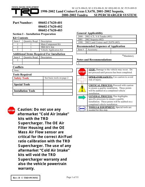
SC-LCX-006-D, SC-LXX-006-D, SC-SEQ-002-D, SC-TUN-009-D<br />
1998-2002 Land Cruiser/Lexus LX470, 2001-2002 Sequoia,<br />
2000-2002 Tundra SUPERCHARGER SYSTEM<br />
Part Number: 00602-17620-401<br />
00602-17620-402<br />
00602-17620-403<br />
Section I – <strong>Installation</strong> Preparation<br />
Kit Contents<br />
Item # Quantity Reqd. Description<br />
1 1 Main Component Kit<br />
2 1 <strong>TRD</strong> ECU Kit<br />
3 1 Vehicle Application Kit<br />
Additional Items Required For <strong>Installation</strong><br />
Item # Quantity Reqd. Description<br />
1<br />
Conflicts<br />
Note:<br />
Tools Required<br />
Safety Tools See basic tools on page 2<br />
Special Tools<br />
<strong>Installation</strong> Tools<br />
Caution: Do not use any<br />
aftermarket “Cold Air Intake”<br />
kits with the <strong>TRD</strong><br />
<strong>Supercharger</strong>. The OE Air<br />
Filter Housing and the OE<br />
Mass Air Flow sensor are<br />
critical for the correct Air/Fuel<br />
ratio calibration with the <strong>TRD</strong><br />
<strong>Supercharger</strong>. The use of any<br />
aftermarket “Cold Air Intake”<br />
kits will void the <strong>TRD</strong><br />
<strong>Supercharger</strong> warranty and<br />
also the vehicle powertrain<br />
warranty.<br />
General Applicability<br />
2000 – 2002 4.7L V-8 Tundra (401)<br />
2001 – 2002 Sequoia (402)<br />
1998 – 2002 Land Cruiser and LX470 (403)<br />
Re<strong>com</strong>mended Sequence of Application<br />
Item # Accessory<br />
Notes and Re<strong>com</strong>mendations<br />
1.<br />
*Mandatory<br />
STOP: Damage to the vehicle may occur. Do<br />
not proceed until process has been <strong>com</strong>pleted.<br />
OPERATOR SAFETY: Use caution to avoid<br />
risk of injury.<br />
CRITICAL PROCESS: Proceed with caution<br />
to ensure a quality installation. These points<br />
will be audited on a <strong>com</strong>pleted vehicle<br />
installation.<br />
GENERAL PROCESS: This highlights<br />
specific processes to ensure a quality<br />
installation. These points will be audited on a<br />
<strong>com</strong>pleted vehicle installation.<br />
TOOLS & EQUIPMENT: Special tools are<br />
needed for this step.<br />
Rev: D © <strong>TRD</strong> 09/30/02<br />
Page 1 of 33
A. Preparation:<br />
SC-LCX-006-D, SC-LXX-006-D, SC-SEQ-002-D, SC-TUN-009-D<br />
1998-2002 Land Cruiser/Lexus LX470, 2001-2002 Sequoia,<br />
2000-2002 Tundra SUPERCHARGER SYSTEM<br />
1. Before you begin, <strong>TRD</strong> re<strong>com</strong>mends that you thoroughly clean the engine<br />
<strong>com</strong>partment. If you don’t, grease buildup on parts could be<strong>com</strong>e dislodged during the<br />
procedure and fall into the engine.<br />
2. Make sure the engine has fully cooled before you begin.<br />
3. To help with re-connecting the vacuum hoses, you should draw diagrams of your engine’s<br />
vacuum hose routing before you disconnect anything. However, some of the vacuum<br />
connections on your stock air intake chamber may not be the same as those on the<br />
supercharger. Study and closely follow the installation <strong>instruction</strong>s for correct vacuum hose<br />
connections.<br />
4. The <strong>TRD</strong> supercharger system has been designed to reuse most of the original equipment<br />
(OE) nuts and bolts. Therefore, as you remove them, keep them with their <strong>com</strong>ponents or<br />
label them for location. This will assure a faster, easier installation.<br />
Re<strong>com</strong>mended Tools:<br />
Basic Tools:<br />
Safety Tools:<br />
Metric Socket Set<br />
Metric Allen-Head Set<br />
Metric Combination Wrench Set<br />
½” Wide Masking Tape for Labeling Hardware and Parts<br />
A Clean Work Bench<br />
A Parts Tray<br />
Rags or Shop Towels<br />
Toyota Sealant # 08826-00100, # 00295-00102 or equivalent RTV Sealant<br />
Special Tools:<br />
Accessories:<br />
Safety Goggles<br />
Toyota Repair Manual: Available from Toyota, 800-622-2033<br />
<strong>TRD</strong> boost gauge (not provided in supercharger kit)<br />
Rev: D © <strong>TRD</strong> 09/30/02<br />
Page 2 of 33
SC-LCX-006-D, SC-LXX-006-D, SC-SEQ-002-D, SC-TUN-009-D<br />
1998-2002 Land Cruiser/Lexus LX470, 2001-2002 Sequoia,<br />
2000-2002 Tundra SUPERCHARGER SYSTEM<br />
B. Removal of Stock Intake Manifold<br />
1. Disconnect negative battery cable.<br />
2. Remove gravel guard on Tundra/Sequoia<br />
(Figure 1). On Land Cruiser and LX470,<br />
remove plastic snap-in access plug on<br />
passenger side of gravel guard.<br />
Figure 1<br />
3. Open radiator petcock, and drain coolant into<br />
a clean pan. Close petcock after coolant has<br />
drained (Figure 2).<br />
Figure 2<br />
4. On Tundra and Sequoia, remove throttle body<br />
cover as shown (Figure 3). On Land Cruiser<br />
and LX470, remove V-Bank cover.<br />
Figure 3<br />
Rev: D © <strong>TRD</strong> 09/30/02<br />
Page 3 of 33
5. Remove A/C suction hose bracket from air<br />
inlet tube (Figure 4). Tundra and Sequoia<br />
only.<br />
SC-LCX-006-D, SC-LXX-006-D, SC-SEQ-002-D, SC-TUN-009-D<br />
1998-2002 Land Cruiser/Lexus LX470, 2001-2002 Sequoia,<br />
2000-2002 Tundra SUPERCHARGER SYSTEM<br />
Figure 4<br />
6. Remove intake air connector (Figure 5).<br />
Tundra and Sequoia shown.<br />
7. Cover throttle body air inlet and air filter<br />
outlet with plastic or shop towels. Use an air<br />
hose to blow any debris from around the<br />
intake manifold ports. This step will help stop<br />
any debris from falling into the intake ports<br />
when the manifold is removed. Caution: Use<br />
safety glasses.<br />
Figure 5<br />
8. Disconnect vacuum hoses from upper intake<br />
manifold. Label all hoses for easier assembly<br />
in later steps (Figure 6).<br />
9. Disconnect throttle cable from throttle body<br />
and remove throttle cable from bracket<br />
(A Arrows, Figure 6).<br />
B<br />
B<br />
A<br />
10. Remove passenger side injector/coil wiring<br />
loom from black nylon retaining clips<br />
(B Arrows, Figure 6).<br />
A<br />
Figure 6<br />
Rev: D © <strong>TRD</strong> 09/30/02<br />
Page 4 of 33
SC-LCX-006-D, SC-LXX-006-D, SC-SEQ-002-D, SC-TUN-009-D<br />
1998-2002 Land Cruiser/Lexus LX470, 2001-2002 Sequoia,<br />
2000-2002 Tundra SUPERCHARGER SYSTEM<br />
11. Disconnect passenger-side injector connectors<br />
from injectors (Arrow A, Figure 7).<br />
12. Disconnect coolant sensor connectors from<br />
water crossover manifold (Arrow B, Figure 7)<br />
13. On Tundra and Sequoia only, disconnect<br />
Mass Air Flow (MAF) connector from MAF<br />
sensor and set connector aside.<br />
A<br />
B<br />
Figure 7<br />
14. Remove driver-side EVAP Vacuum Switched<br />
Valve (VSV) and throttle cable bracket from<br />
upper intake manifold. On Tundra / Sequoia,<br />
one bolt secures both parts (Figure 8). On<br />
Land Cruiser and LX470, one bolt secures<br />
EVAP VSV and a second bolt secures the<br />
throttle cable bracket.<br />
15. On Tundra and Sequoia, remove driver-side<br />
injector/coil wire loom from plastic retaining<br />
clips.<br />
Figure 8<br />
16. On Land Cruiser and LX470, remove driverside<br />
wire loom housing from the intake<br />
manifold (Figure 9).<br />
17. Remove driver-side injector connectors from<br />
injectors.<br />
Figure 9<br />
Rev: D © <strong>TRD</strong> 09/30/02<br />
Page 5 of 33
18. Remove PCV valve hose from throttle body<br />
and cam cover (Figure 10).<br />
SC-LCX-006-D, SC-LXX-006-D, SC-SEQ-002-D, SC-TUN-009-D<br />
1998-2002 Land Cruiser/Lexus LX470, 2001-2002 Sequoia,<br />
2000-2002 Tundra SUPERCHARGER SYSTEM<br />
Figure 10<br />
19. Disconnect throttle motor and throttle position<br />
sensor (TPS) connectors (Figure 11).<br />
20. Remove throttle body and disconnect water<br />
bypass hoses. Disconnect upper hose from<br />
throttle body and oil cooler pipe. Disconnect<br />
lower hose at water crossover fitting only.<br />
21. On Land Cruiser and LX470, disconnect the<br />
ground strap from the engine-lifting hook on<br />
the driver-side of the engine.<br />
22. Remove and replace the fuel cap to relieve<br />
pressure from the fuel system.<br />
Figure 11<br />
23. Place a shop towel under the fuel main hose at<br />
the fuel delivery pipe connection point.<br />
Remove the pulsation damper, upper and<br />
lower gaskets, and set the fuel main hose<br />
aside (Figure 12). Caution: Fuel spillage will<br />
occur. Retain the gaskets for reuse.<br />
24. Remove OE rubber fuel return hose from fuel<br />
pressure regulator on passenger-side of<br />
engine.<br />
Figure 12<br />
Rev: D © <strong>TRD</strong> 09/30/02<br />
Page 6 of 33
SC-LCX-006-D, SC-LXX-006-D, SC-SEQ-002-D, SC-TUN-009-D<br />
1998-2002 Land Cruiser/Lexus LX470, 2001-2002 Sequoia,<br />
2000-2002 Tundra SUPERCHARGER SYSTEM<br />
25. Remove OE clamp from front fuel pipe<br />
(Arrow A, Figure 13); save clamp for use<br />
with the 9 th injector fuel supply line. Remove<br />
2 banjo bolts (B Arrows, Figure 13), 4 gaskets<br />
and front fuel pipe. Caution: Fuel pipe<br />
contains fuel that may spill.<br />
B<br />
B<br />
A<br />
Figure 13<br />
26. Remove OE fuel return hose from fuel return<br />
pipe (Figure 14). Fuel return pipe is secured<br />
to backside of upper intake manifold. Plug<br />
rubber hose and set aside.<br />
27. Unbolt the OE steel clamp that secures the<br />
fuel return pipe to the backside of the driverside<br />
delivery pipe (Figure 14).<br />
Clamp<br />
Figure 14<br />
28. Remove the 4 nuts that secure the fuel<br />
delivery pipes to the lower intake manifold<br />
(Figure 15).<br />
29. Remove the 2 fuel delivery pipes, 8 injectors,<br />
and 8 insulators. Retain the injectors, the<br />
insulators and fuel pipe spacers, as they will<br />
be reused.<br />
Figure 15<br />
Rev: D © <strong>TRD</strong> 09/30/02<br />
Page 7 of 33
SC-LCX-006-D, SC-LXX-006-D, SC-SEQ-002-D, SC-TUN-009-D<br />
1998-2002 Land Cruiser/Lexus LX470, 2001-2002 Sequoia,<br />
2000-2002 Tundra SUPERCHARGER SYSTEM<br />
30. On Land Cruiser and LX470, disconnect<br />
engine ground wire connector near firewall<br />
(Arrow A, Figure 16).<br />
A<br />
B<br />
Figure 16<br />
31. Remove the 6 bolts and 4 nuts that secure the<br />
intake manifold assembly (Figure 17). Do not<br />
remove the bolts that attach the top manifold<br />
to the bottom manifold. Remove the intake<br />
manifold. Caution: To avoid coolant<br />
leakage, do not hit heater pipe riser (Arrow<br />
B, Figure 16).<br />
32. Remove both driver-side and passenger-side<br />
engine hangers.<br />
33. Inspect both intake manifold gaskets; they<br />
may be re-used if the gaskets are in good<br />
shape. Caution: Use shop towels to cover all<br />
eight oval intake ports.<br />
Figure 17<br />
34. Remove clamp from lower radiator hose at<br />
thermostat housing and disconnect hose<br />
(Figure 18).<br />
35. Remove the 3 OE nuts that secure the water<br />
inlet to the water inlet housing.<br />
36. Remove water inlet, OE thermostat, and<br />
gasket from water inlet housing.<br />
Figure 18<br />
Rev: D © <strong>TRD</strong> 09/30/02<br />
Page 8 of 33
SC-LCX-006-D, SC-LXX-006-D, SC-SEQ-002-D, SC-TUN-009-D<br />
1998-2002 Land Cruiser/Lexus LX470, 2001-2002 Sequoia,<br />
2000-2002 Tundra SUPERCHARGER SYSTEM<br />
37. Disconnect water bypass hose from the water<br />
inlet housing. Remove the 2 bolts that secure<br />
the water inlet housing to the water pump, and<br />
remove water inlet housing (Figure 19).<br />
38. Loosen the alternator drive belt by turning the<br />
belt tensioner counter-clockwise, and remove<br />
the drive belt.<br />
Figure 19<br />
39. Remove drive belt idler pulley (Figure 20).<br />
Note: The water crossover casting and the<br />
upper radiator hose are removed in this<br />
picture for clarity. DO NOT REMOVE<br />
these parts.<br />
Figure 20<br />
Rev: D © <strong>TRD</strong> 09/30/02<br />
Page 9 of 33
SC-LCX-006-D, SC-LXX-006-D, SC-SEQ-002-D, SC-TUN-009-D<br />
1998-2002 Land Cruiser/Lexus LX470, 2001-2002 Sequoia,<br />
2000-2002 Tundra SUPERCHARGER SYSTEM<br />
40. Install the supplied ½” x 17” rubber hose on<br />
the oil cooler pipe. Use the supplied <strong>TRD</strong><br />
hose clamps to secure hose (Figure 21).<br />
Caution: Position hose clamp ears (tangs)<br />
away from the belt.<br />
Note: The water crossover casting and the<br />
upper radiator hose are removed in this<br />
picture for clarity. DO NOT REMOVE<br />
these parts.<br />
Figure 21<br />
41. Re-install the OE water bypass hose removed<br />
in Step 37 back onto the oil cooler pipe. Reuse<br />
the OE hose clamps. Leave one clamp<br />
halfway down hose (Figure 22).<br />
Note: The water crossover casting and the<br />
upper radiator hose are removed in this<br />
picture for clarity. DO NOT REMOVE<br />
these parts.<br />
42. Rinse all OE pulleys with fresh water and<br />
blow dry with <strong>com</strong>pressed air to clean any<br />
spilled coolant off, otherwise the belt may slip<br />
and squeal.<br />
Figure 22<br />
Rev: D © <strong>TRD</strong> 09/30/02<br />
Page 10 of 33
SC-LCX-006-D, SC-LXX-006-D, SC-SEQ-002-D, SC-TUN-009-D<br />
1998-2002 Land Cruiser/Lexus LX470, 2001-2002 Sequoia,<br />
2000-2002 Tundra SUPERCHARGER SYSTEM<br />
43. Insert the supplied idler bushing into the<br />
backside of the <strong>TRD</strong> idler pulley (Figure 23).<br />
Caution: Bushing can be inserted either<br />
way into pulley. Front of pulley has a<br />
rounded edge; rear of pulley has a sharp<br />
edge.<br />
Figure<br />
44. Install the supplied idler pulley and bushing.<br />
Use the OE bolt (Figure 24). The rounded<br />
edge of the idler pulley faces to the front of<br />
the vehicle. Torque bolt: 39 N-m (29 ft-lbf).<br />
Figure 24<br />
45. Apply Toyota Sealant Part # 08826-00100,<br />
# 00295-00102, or equivalent to water inlet<br />
housing (Figure 25).<br />
Figure 25<br />
Rev: D © <strong>TRD</strong> 09/30/02<br />
Page 11 of 33
SC-LCX-006-D, SC-LXX-006-D, SC-SEQ-002-D, SC-TUN-009-D<br />
1998-2002 Land Cruiser/Lexus LX470, 2001-2002 Sequoia,<br />
2000-2002 Tundra SUPERCHARGER SYSTEM<br />
46. Install water inlet housing with <strong>TRD</strong> supplied<br />
bolts (Figure 26). Slide hose nipple fitting<br />
into the OE rubber hose that was installed in<br />
Step 41. Torque inlet housing bolts: 18 N-m<br />
(13 ft-lbf).<br />
47. Secure rubber hose to hose nipple using the<br />
OE hose clamp installed in Step 41.<br />
Figure 26<br />
48. Install new supplied thermostat, and gasket<br />
into <strong>TRD</strong> water inlet housing (Figure 27).<br />
Note: The new gasket is packaged in the<br />
black cardboard box at the thermostat<br />
base.<br />
49. Position thermostat jiggle valve in the vertical<br />
position (Figure 27).<br />
50. Install OE water inlet to water inlet housing<br />
using 3 OE nuts removed in Step 35. Torque<br />
to 19 N-m (14 ft-lbf).<br />
Figure 27<br />
51. On Land Cruiser and LX470, use two <strong>TRD</strong>supplied<br />
relocation brackets and two 6mm<br />
bolts to move wire loom housing towards<br />
firewall (Figure 28). Torque: 7.5 N-m<br />
(66 in.-lbf).<br />
Figure 28<br />
Rev: D © <strong>TRD</strong> 09/30/02<br />
Page 12 of 33
SC-LCX-006-D, SC-LXX-006-D, SC-SEQ-002-D, SC-TUN-009-D<br />
1998-2002 Land Cruiser/Lexus LX470, 2001-2002 Sequoia,<br />
2000-2002 Tundra SUPERCHARGER SYSTEM<br />
NOTE: Do not lift the supercharger by the 9 th<br />
injector and/or fuel damper.<br />
52. Remove the 2 upper nuts that secure the<br />
bypass actuator bracket to the <strong>TRD</strong> manifold.<br />
Make sure to note the orientation of the<br />
actuator shaft (for reassembly), and then<br />
remove the bypass assembly and spacers from<br />
the manifold (Figure 29).<br />
Figure 29<br />
53. Remove EVAP steel crossover tube from the<br />
OE intake manifold (Arrow A, Figure 30).<br />
54. Remove OE rubber fuel hose from the steel<br />
fuel return line on the backside of the OE<br />
intake manifold (Arrow B, Figure 30). Retain<br />
the rubber hose for reuse.<br />
55. Remove steel clamp from the OE steel fuel<br />
return line (Arrow C, Figure 30).<br />
56. On Land Cruiser and LX470, remove engine<br />
ground wire from intake manifold (ignore this<br />
step for Tundra and Sequoia).<br />
A<br />
C<br />
Figure 30<br />
B<br />
57. Remove throttle cable bracket from OE intake<br />
manifold. Tundra and Sequoia bracket shown<br />
(Figure 31).<br />
Figure 31<br />
Rev: D © <strong>TRD</strong> 09/30/02<br />
Page 13 of 33
SC-LCX-006-D, SC-LXX-006-D, SC-SEQ-002-D, SC-TUN-009-D<br />
1998-2002 Land Cruiser/Lexus LX470, 2001-2002 Sequoia,<br />
2000-2002 Tundra SUPERCHARGER SYSTEM<br />
58. On Tundra and Sequoia only, remove 1/8”<br />
NPT plug and install 1/8” NPT x 3/8” barb<br />
fitting into supercharger plenum (Figure 32).<br />
59. Remove OE throttle cable support bracket<br />
from OE intake manifold.<br />
Figure 32<br />
60. On Tundra and Sequoia, install the OE<br />
throttle cable support bracket (Arrow A,<br />
Figure 33) onto the <strong>TRD</strong> supercharger<br />
manifold using the OE 8mm bolt. On Land<br />
Cruiser/LX470, the OE bracket has a 6mm<br />
hole. Drill the bracket hole to 8mm or 21/64.<br />
61. Install the Land Cruiser/LX470 throttle cable<br />
support bracket using the supplied 25.4mm<br />
(1.0 inch) spacer, and supplied 8mm bolt<br />
(Arrow B, Figure 33).<br />
A<br />
B<br />
Figure 33<br />
62. Insert the OE rubber fuel return hose removed<br />
in Step 54 through the Adel clamp mounted<br />
on the passenger-side of the <strong>TRD</strong> manifold<br />
(Figure 34).<br />
Figure 34<br />
Rev: D © <strong>TRD</strong> 09/30/02<br />
Page 14 of 33
SC-LCX-006-D, SC-LXX-006-D, SC-SEQ-002-D, SC-TUN-009-D<br />
1998-2002 Land Cruiser/Lexus LX470, 2001-2002 Sequoia,<br />
2000-2002 Tundra SUPERCHARGER SYSTEM<br />
63. To allow access to the 8mm bolt on the<br />
supercharger inlet elbow (Arrow A, Figure<br />
35), loosen the passenger-side bolt that<br />
secures the 9 th injector fuel rail and rotate the<br />
assembly. Remove the 8mm bolt.<br />
64. Install the supplied steel fuel return line to the<br />
inlet elbow. Connect the OE rubber fuel<br />
return hose to the steel line (Arrow B, Figure<br />
35). Re-use the OE hose clamp. Torque the<br />
8mm bolt to 21 N-m (15 ft-lbf).<br />
A<br />
B<br />
Figure 35<br />
65. Install the supplied nylon wrap over the<br />
passenger-side heater hose (Figure 36). Install<br />
wrap just above the OE heater hose clamp.<br />
Caution: Position OE clamp as shown.<br />
Figure 36<br />
66. Re-install EVAP steel crossover line removed<br />
in Step 53 (Arrow A, Figure 37). On Land<br />
Cruiser/LX470 only, secure engine ground<br />
wire (removed in Step 56) between EVAP<br />
line bracket and intake manifold (Arrow B,<br />
Figure 37).<br />
67. Remove the shop towels that are covering the<br />
intake gaskets and ports on the engine.<br />
68. Check the <strong>TRD</strong> supercharger manifold base<br />
where it will contact the intake manifold<br />
gaskets. Clean supercharger manifold base if<br />
necessary.<br />
Figure 37<br />
A<br />
B<br />
Rev: D © <strong>TRD</strong> 09/30/02<br />
Page 15 of 33
C. <strong>Installation</strong> of <strong>Supercharger</strong><br />
SC-LCX-006-D, SC-LXX-006-D, SC-SEQ-002-D, SC-TUN-009-D<br />
1998-2002 Land Cruiser/Lexus LX470, 2001-2002 Sequoia,<br />
2000-2002 Tundra SUPERCHARGER SYSTEM<br />
1. Use two people to carefully set the <strong>TRD</strong><br />
supercharger manifold into place on the<br />
intake manifold gaskets (Figure 38). Caution:<br />
To avoid coolant leakage, do not hit steel<br />
heater pipe as mentioned in Step 31 of Part<br />
B, Page 8 (refer to Figure 16, Arrow B).<br />
2. Check supercharger manifold to be sure it sits<br />
flat on the intake gaskets. Install OE manifold<br />
6 bolts and 4 nuts. Uniformly tighten the bolts<br />
and nuts in several passes. Torque to 18 N-m<br />
(13 ft-lbf).<br />
Figure 38<br />
3. Install OE passenger-side fuel delivery pipe<br />
spacers (Figure 39).<br />
4. Install 4 insulators, 4 injectors and passengerside<br />
fuel delivery pipe (Figure 40). Use OE<br />
fuel delivery pipe nuts. Torque to 7.5 N-m<br />
(66 in.-lbf).<br />
Figure 39<br />
Figure 40<br />
Rev: D © <strong>TRD</strong> 09/30/02<br />
Page 16 of 33
SC-LCX-006-D, SC-LXX-006-D, SC-SEQ-002-D, SC-TUN-009-D<br />
1998-2002 Land Cruiser/Lexus LX470, 2001-2002 Sequoia,<br />
2000-2002 Tundra SUPERCHARGER SYSTEM<br />
5. Install OE fuel return hose on fuel pressure<br />
regulator. Use OE hose clamp to secure hose<br />
(Figure 41). Be sure to position the hose<br />
clamp with the ears (tangs) up.<br />
Figure 41<br />
6. Locate bypass valve kit supplied in <strong>TRD</strong><br />
supercharger package. Remove the solenoid<br />
valve, and 6mm flange-head bolt. Place<br />
bypass actuator assembly as shown in Figure<br />
42, and secure solenoid valve to the actuator<br />
bracket as shown.<br />
Torque: 10 N-m (89 in.-lbf). Note: Mount<br />
the solenoid valve so that the steel barb<br />
points towards the firewall and the foam<br />
filter points towards the front of the<br />
vehicle. The unit mounts on the<br />
supercharger side of the bracket (See<br />
Figure 43).<br />
Foam Filter<br />
Figure 42<br />
Steel Barb<br />
7. Install supercharger bypass actuator assembly.<br />
Use <strong>TRD</strong> supplied nuts and spacers removed<br />
in Step 52. (Arrow A, Figure 43). Caution:<br />
Check that bypass actuator rod does not<br />
interfere with OE fuel return hose (Arrow<br />
B, Figure 43). Verify the shaft engagement<br />
into the actuator slot.<br />
A<br />
B<br />
Note: On Tundra and Sequoia perform Steps 8<br />
- 13 then skip Steps 14 - 17. On Land Cruiser<br />
and LX470, skip Steps 8 - 13 and perform<br />
Steps 14 – 17. Continue with Step 18 for all<br />
models.<br />
Figure 43<br />
Rev: D © <strong>TRD</strong> 09/30/02<br />
Page 17 of 33
Tundra / Sequoia only<br />
SC-LCX-006-D, SC-LXX-006-D, SC-SEQ-002-D, SC-TUN-009-D<br />
1998-2002 Land Cruiser/Lexus LX470, 2001-2002 Sequoia,<br />
2000-2002 Tundra SUPERCHARGER SYSTEM<br />
8. Install cable tie mount to unused boss on<br />
passenger-side cam cover. Secure cable tie<br />
mount with supplied 6mm Button-head bolt<br />
and 6mm washer (Figure 44).<br />
9. Re-connect 4 passenger-side injector<br />
connectors to fuel injectors.<br />
10. Re-connect coolant sensor connectors to<br />
coolant sensors.<br />
11. Use supplied cable tie to secure wire loom to<br />
cable tie mount (Figure 45).<br />
Figure 44<br />
Figure 45<br />
12. Remove the rear OE wire loom bracket from<br />
the passenger-side fuel delivery pipe.<br />
13. Secure the wire loom using the front OE<br />
bracket (Figure 46).<br />
Figure 46<br />
Rev: D © <strong>TRD</strong> 09/30/02<br />
Page 18 of 33
Land Cruiser / LX470 only<br />
SC-LCX-006-D, SC-LXX-006-D, SC-SEQ-002-D, SC-TUN-009-D<br />
1998-2002 Land Cruiser/Lexus LX470, 2001-2002 Sequoia,<br />
2000-2002 Tundra SUPERCHARGER SYSTEM<br />
14. Use supplied #16 Adel clamp to secure wire<br />
loom to bypass actuator bracket. (Figure 47).<br />
Torque bolt to 18 N-m (13 ft-lbf).<br />
15. Remove the 2 OE wire loom brackets from<br />
the passenger-side fuel delivery pipe.<br />
Figure 47<br />
16. Turn the brackets upside down and re-attach<br />
to the fuel delivery pipe using the OE bolts<br />
(Figure 48).<br />
17. Secure wire loom using the OE brackets<br />
installed in the previous step.<br />
All models<br />
18. Check the passenger-side wire loom clearance<br />
to bypass actuator assembly, linkage and rod.<br />
The wire loom should clear all bypass<br />
actuator <strong>com</strong>ponents. If the wire loom is too<br />
close to any bypass actuator <strong>com</strong>ponents, then<br />
re-check steps 8 – 13 for Tundra/Sequoia, and<br />
steps 14 – 17 for Land Cruiser/LX470.<br />
Additional cable ties may be used to secure<br />
the wire loom away from the bypass actuator<br />
assembly.<br />
Figure 48<br />
Rev: D © <strong>TRD</strong> 09/30/02<br />
Page 19 of 33
19. Install OE driver-side fuel delivery pipe<br />
spacers (Figure 49 and 50).<br />
SC-LCX-006-D, SC-LXX-006-D, SC-SEQ-002-D, SC-TUN-009-D<br />
1998-2002 Land Cruiser/Lexus LX470, 2001-2002 Sequoia,<br />
2000-2002 Tundra SUPERCHARGER SYSTEM<br />
20. Install 4 insulators, 4 injectors and driver-side<br />
fuel delivery pipe (Figure 49 and 50). Use OE<br />
fuel delivery pipe nuts. Torque to 7.5 N-m (66<br />
in.-lbf).<br />
21. Reconnect the driver-side injector wires to the<br />
fuel injectors.<br />
Figure 49<br />
22. Use the OE clamp removed in Step 55 (Part<br />
B, Page 13) to secure the <strong>TRD</strong> fuel return line<br />
to the rear of the driver-side fuel delivery<br />
pipe (Arrow A, Figure 50). Torque OE bolt to<br />
7.5 N-m (66in.-lbf).<br />
23. Re-connect the OE fuel return hose to the<br />
<strong>TRD</strong> return line using the OE hose clamp<br />
(Figure 50).<br />
24. Re-install the lower gasket, fuel main hose,<br />
upper gasket and fuel pulsation damper. Use<br />
SST # 09612-24014 (09617-24011) to tighten<br />
damper. Torque the damper to 33 N-m (24 ftlbf)<br />
for use with SST, 39 N-m (29 ft-lbf)<br />
without SST.<br />
Figure 50<br />
A<br />
25. Position the OE front fuel pipe bracket<br />
removed in Step 25 (Part B, Page 7) onto the<br />
supplied 9 th injector fuel delivery line.<br />
Position the bracket 10 ½” from the banjo<br />
centerline along the longest straight section of<br />
the tube (Figure 51).<br />
OE Bracket<br />
Figure 51<br />
Rev: D © <strong>TRD</strong> 09/30/02<br />
Page 20 of 33
SC-LCX-006-D, SC-LXX-006-D, SC-SEQ-002-D, SC-TUN-009-D<br />
1998-2002 Land Cruiser/Lexus LX470, 2001-2002 Sequoia,<br />
2000-2002 Tundra SUPERCHARGER SYSTEM<br />
26. Position the 9 th injector fuel delivery line next<br />
to the intake runners on the driver-side. The<br />
line will fit between the OE fuel damper and<br />
the intake runners (Figure 52).<br />
27. Use the <strong>TRD</strong> supplied banjo bolt and gaskets<br />
to install the 9 th injector fuel delivery line.<br />
Starting from the top, the correct order is<br />
<strong>TRD</strong> banjo bolt, gasket, 9 th injector line,<br />
gasket, <strong>TRD</strong> front fuel pipe, gasket, and<br />
finally the OE driver-side delivery pipe<br />
(Figure 52). Leave the <strong>TRD</strong> banjo bolt fingertight<br />
at this time.<br />
28. Connect the <strong>TRD</strong> supplied front fuel pipe to<br />
the passenger-side delivery pipe by using the<br />
OE banjo bolt and supplied gaskets. Fingertighten<br />
the banjo bolt at this time (Figure 53).<br />
Figure 52<br />
Figure 53<br />
Rev: D © <strong>TRD</strong> 09/30/02<br />
Page 21 of 33
SC-LCX-006-D, SC-LXX-006-D, SC-SEQ-002-D, SC-TUN-009-D<br />
1998-2002 Land Cruiser/Lexus LX470, 2001-2002 Sequoia,<br />
2000-2002 Tundra SUPERCHARGER SYSTEM<br />
29. Use the remaining OE banjo bolt and supplied<br />
gaskets to secure the 9 th injector fuel delivery<br />
line to the <strong>TRD</strong> fuel rail on the backside of<br />
the intake manifold (Figure 54). Leave the<br />
banjo bolt finger-tight at this time.<br />
Figure 54<br />
30. Use the OE 6mm fuel pipe bolt to secure the<br />
9 th injector fuel line bracket to the mounting<br />
hole on the driver-side of the <strong>TRD</strong> intake<br />
manifold (Arrow A, Figure 55). Torque bolt:<br />
7.5 N-m (66 in.-lbf)<br />
31. Check the routing of the 9 th injector fuel<br />
delivery line. It should be centered between<br />
the # 7 intake runner and the OE fuel damper<br />
(Arrow B, Figure 55). The line should not<br />
touch any <strong>com</strong>ponents.<br />
32. Torque all three fuel-line banjo fittings to 39<br />
N-m (29 ft-lbf).<br />
33. Install the supercharger nose support bracket.<br />
Adjust the nose support bracket to fit snug<br />
against the supercharger nose. Secure the<br />
bracket with the supplied 8mm flange-head<br />
bolt and flange-head nut (Figure 56). Torque<br />
the fasteners to 18 N-m (13 ft-lbf).<br />
A<br />
Figure 55<br />
B<br />
Figure 56<br />
Rev: D © <strong>TRD</strong> 09/30/02<br />
Page 22 of 33
SC-LCX-006-D, SC-LXX-006-D, SC-SEQ-002-D, SC-TUN-009-D<br />
1998-2002 Land Cruiser/Lexus LX470, 2001-2002 Sequoia,<br />
2000-2002 Tundra SUPERCHARGER SYSTEM<br />
34. Move the throttle body close to the front of<br />
the manifold and re-attach the water bypass<br />
hoses. Attach the lower hose to the fitting in<br />
the water crossover manifold. Re-use the OE<br />
clamp (Figure 57). Attach the ½” upper hose<br />
to the throttle body from the oil cooler pipe.<br />
Use the supplied clamp to secure hose.<br />
Figure 57<br />
35. Re-use the OE throttle body gasket and install<br />
the throttle body. Use the 2 OE lower bolts<br />
and the 2 <strong>TRD</strong>-supplied upper bolts to secure<br />
the throttle body (Figure 58). Torque to 18 N-<br />
m (13 ft-lbf).<br />
36. Re-connect the TPS and throttle motor<br />
connectors to the TPS sensor and the throttle<br />
motor (Figure 59).<br />
37. Loosen the throttle motor connector bracket<br />
(Phillip's head screw). Rotate the bracket 180<br />
degrees and reinstall the screw.<br />
Figure 58<br />
Figure 59<br />
Rev: D © <strong>TRD</strong> 09/30/02<br />
Page 23 of 33
38. Remove water bypass hose bracket. It is no<br />
longer used (Figure 60).<br />
SC-LCX-006-D, SC-LXX-006-D, SC-SEQ-002-D, SC-TUN-009-D<br />
1998-2002 Land Cruiser/Lexus LX470, 2001-2002 Sequoia,<br />
2000-2002 Tundra SUPERCHARGER SYSTEM<br />
Figure 60<br />
39. Locate the A/C <strong>com</strong>pressor on the driver'sside<br />
of the engine and remove both the OE<br />
flange-head nut (Arrow A, Figure 61) and the<br />
8mm bolt (Arrow B, Figure 61).<br />
B<br />
A<br />
Figure 61<br />
40. Mount the <strong>TRD</strong>-supplied idler pulley bracket<br />
using the OE flange-head nut (Arrow A,<br />
Figure 62) and the supplied 8mm flange-head<br />
bolt (Arrow B, Figure 62). Torque bolt to 16<br />
N-m (12 ft-lbf) and the nut 32 N-m (24 ft-lbf).<br />
B<br />
A<br />
Figure 62<br />
Rev: D © <strong>TRD</strong> 09/30/02<br />
Page 24 of 33
SC-LCX-006-D, SC-LXX-006-D, SC-SEQ-002-D, SC-TUN-009-D<br />
1998-2002 Land Cruiser/Lexus LX470, 2001-2002 Sequoia,<br />
2000-2002 Tundra SUPERCHARGER SYSTEM<br />
41. Insert the supplied 10mm flange-head bolt<br />
through the idler pulley and pulley spacer.<br />
Install the idler pulley and spacer to the idler<br />
bracket (Figure 63). Torque the bolt to<br />
39 N-m (29 ft-lbf).<br />
Figure 63<br />
42. Install <strong>TRD</strong>-supplied drive belt. Use the belt<br />
routing shown in Figure 64. Tundra trucks use<br />
a 2700mm long, 6-rib belt. Sequoia, Land<br />
Cruiser and LX470 use a 2630mm long, 6-rib<br />
belt.<br />
43. Select a suitable location under the vehicle<br />
hood and install the <strong>TRD</strong> supplied belt<br />
routing sticker. Clean the area first of any dirt<br />
or contamination. Note: Do not cover any<br />
OE stickers.<br />
44. Select two additional locations under the<br />
vehicle hood to mount both the supplied<br />
CARB Executive Order (EO) emissions<br />
<strong>com</strong>pliance sticker, and the <strong>TRD</strong> tune-up<br />
sticker. The <strong>TRD</strong> tune-up sticker specifies the<br />
re<strong>com</strong>mended <strong>com</strong>ponents for use with the<br />
4.7 V-8 supercharger system. Clean both<br />
areas first of any dirt or contamination.<br />
Note: Do not cover any OE stickers.<br />
45. On Tundra and Sequoia, connect supplied<br />
rubber hose from the vacuum canister to the<br />
3/8” brass barb in the <strong>TRD</strong> manifold cover.<br />
Use a supplied spring clamp on each end of<br />
the hose. (Figure 65)<br />
Spring<br />
Clamp<br />
Figure 64<br />
Spring<br />
Clamp<br />
46. Re-install the lower radiator hose. Use the OE<br />
clamp to secure the hose. Note: Make sure to<br />
rotate the hose so that it clears the power<br />
steering pulley.<br />
47. Fill the cooling system with coolant removed<br />
in Step 3 (Part B, Page 3).<br />
Figure 65<br />
Vacuum Hose<br />
Rev: D © <strong>TRD</strong> 09/30/02<br />
Page 25 of 33
SC-LCX-006-D, SC-LXX-006-D, SC-SEQ-002-D, SC-TUN-009-D<br />
1998-2002 Land Cruiser/Lexus LX470, 2001-2002 Sequoia,<br />
2000-2002 Tundra SUPERCHARGER SYSTEM<br />
48. Re-install the gravel guard on<br />
Tundra/Sequoia. On Land Cruiser and<br />
LX470, re-install plastic snap-in access plug<br />
in gravel guard (Passenger Side).<br />
49. Remove the 1/8” NPT plug in the <strong>TRD</strong><br />
manifold cover, and replace with the supplied<br />
90-degree brass hose fitting. Use Teflon pipe<br />
sealant on the threads (Figure 66). Connect<br />
supplied 3/16” x 29” long hose to the 90-<br />
degree brass fitting (Arrow A, Figure 66). The<br />
hose is covered by a 26” long split nylon tube<br />
for abrasion resistance. Route hose as shown<br />
behind the manifold cover (Arrow B, Figure<br />
66).<br />
Note: On Tundra and Sequoia vehicles,<br />
skip to Step 61. On Land Cruiser and<br />
LX470 vehicles, perform Steps 50 – 60 and<br />
then skip Steps 61 – 64.<br />
Remove 1/8”<br />
NPT plug.<br />
Install 90-<br />
degree hose<br />
fitting here.<br />
A<br />
Figure 66<br />
B<br />
Land Cruiser / LX470<br />
50. Re-connect the engine ground wire from the<br />
intake manifold to the OE ground wire from<br />
the firewall.<br />
51. Remove two 6mm bolts from the <strong>TRD</strong><br />
manifold cover as shown in Figure 67.<br />
Figure 67<br />
52. Install the supplied bracket to the rearmounting<br />
hole on the driver-side wire loom<br />
housing. Use the supplied 6mm flange-head<br />
bolt (Figure 68).<br />
Figure 68<br />
Rev: D © <strong>TRD</strong> 09/30/02<br />
Page 26 of 33
SC-LCX-006-D, SC-LXX-006-D, SC-SEQ-002-D, SC-TUN-009-D<br />
1998-2002 Land Cruiser/Lexus LX470, 2001-2002 Sequoia,<br />
2000-2002 Tundra SUPERCHARGER SYSTEM<br />
53. Install the EVAP VSV and the supplied front<br />
wire loom bracket using the <strong>TRD</strong> intake<br />
manifold bolt. The wire loom bracket is<br />
placed on the topside of the OE VSV bracket<br />
(Arrow A, Figure 69). Torque to 16 N-m (12<br />
ft-lbf).<br />
54. Secure the wire loom rear bracket to the <strong>TRD</strong><br />
manifold by using the 6mm bolt removed in<br />
Step 51. Leave the bolt finger tight (Arrow B,<br />
Figure 69).<br />
A<br />
B<br />
Figure 69<br />
55. Use the supplied 6mm flange-head bolt to<br />
secure the wiring loom housing to front<br />
bracket (Arrow A, Figure 70). Torque to 7.5<br />
N-m (66in.-lbf).<br />
56. Tighten the 6mm bolt to secure the wire loom<br />
housing rear bracket to the <strong>TRD</strong> manifold<br />
(Arrow B, Figure 70). Torque to 16 N-m (12<br />
ft-lbf).<br />
57. Use a 10mm <strong>com</strong>bination wrench to tighten<br />
the 6mm flange-head bolt that secures the<br />
wire loom housing rear bracket to the housing<br />
(Arrow C, Figure 70).<br />
A<br />
Figure 70<br />
C<br />
B<br />
58. Cut 4 inches off the OE VSV vacuum hose as<br />
shown in Figure 71.<br />
Figure 71<br />
Rev: D © <strong>TRD</strong> 09/30/02<br />
Page 27 of 33
SC-LCX-006-D, SC-LXX-006-D, SC-SEQ-002-D, SC-TUN-009-D<br />
1998-2002 Land Cruiser/Lexus LX470, 2001-2002 Sequoia,<br />
2000-2002 Tundra SUPERCHARGER SYSTEM<br />
59. Connect the EVAP VSV vacuum hose to the<br />
VSV and the 3/8” hose nipple on the <strong>TRD</strong><br />
manifold. Use OE clamps to secure the hose<br />
(Figure 72).<br />
60. Re-connect the VSV electrical connector to<br />
the VSV (Figure 72).<br />
Tundra / Sequoia<br />
Figure 72<br />
61. Remove one 6mm bolt in the <strong>TRD</strong> manifold.<br />
Bolt location shown in Figure 73, Arrow A.<br />
B<br />
D<br />
62. Secure the EVAP VSV with the 6mm bolt<br />
removed in the previous step. Torque to 16<br />
N-m (12 ft-lbf). Complete installation shown<br />
in Figure 73.<br />
E<br />
A<br />
63. Connect the EVAP VSV vacuum hose to the<br />
VSV and the 3/8” hose nipple on the <strong>TRD</strong><br />
manifold. Use OE clamps to secure the hose<br />
(B Arrows, Figure 73).<br />
64. Re-connect the VSV electrical connector to<br />
the VSV (Arrow C, Figure 73).<br />
All models<br />
B<br />
Figure 73<br />
C<br />
65. Re-connect the EVAP canister vacuum hose<br />
removed in Part B, Step 8 on Page 4 (Arrow<br />
D, Figure 73).<br />
66. Re-install the PCV valve hose (Arrow E,<br />
Figure 73).<br />
B<br />
B<br />
A<br />
67. Install throttle cable bracket to the <strong>TRD</strong><br />
intake manifold cover using the supplied<br />
8mm bolts. Use A Arrows location for<br />
Tundra/Sequoia. Use B Arrows location for<br />
Land Cruiser/LX470. (Figure 74). Torque: 18<br />
N-m (13 ft-lbf).<br />
A<br />
68. Re-install throttle cable into bracket, and<br />
connect cable to throttle body. (Figure 74).<br />
Figure 74<br />
Rev: D © <strong>TRD</strong> 09/30/02<br />
Page 28 of 33
69. Re-install the OE breather hose on the<br />
passenger-side cam cover. Connect it to the<br />
cam cover only at this time (Figure 75).<br />
SC-LCX-006-D, SC-LXX-006-D, SC-SEQ-002-D, SC-TUN-009-D<br />
1998-2002 Land Cruiser/Lexus LX470, 2001-2002 Sequoia,<br />
2000-2002 Tundra SUPERCHARGER SYSTEM<br />
Figure 75<br />
70. Install the supplied 7/32” x 8” long bypass<br />
actuator hose to the lower port of the boost<br />
actuator and the front (plastic) nipple on the<br />
solenoid (Arrow A, Figure 76).<br />
71. Re-connect the OE power steering idle-up<br />
hose to the hose nipple on the <strong>TRD</strong> manifold<br />
(Arrow B, Figure 76).<br />
A<br />
C<br />
B<br />
72. Re-connect the EVAP canister hose to the OE<br />
steel line that is secured on the <strong>TRD</strong> manifold<br />
cover. (Arrow C, Figure 76).<br />
73. Connect the fuel pressure regulator hose to<br />
the regulator only at this time (Arrow D,<br />
Figure 76).<br />
Figure 76<br />
D<br />
Rev: D © <strong>TRD</strong> 09/30/02<br />
Page 29 of 33
SC-LCX-006-D, SC-LXX-006-D, SC-SEQ-002-D, SC-TUN-009-D<br />
1998-2002 Land Cruiser/Lexus LX470, 2001-2002 Sequoia,<br />
2000-2002 Tundra SUPERCHARGER SYSTEM<br />
74. Connect the 3/16” x 29” inch long hose<br />
(installed in Step 49) to the nipple on the<br />
backside of the actuator solenoid. See Arrow<br />
in Figure 77.<br />
Connect Here<br />
Figure 77<br />
75. Connect the supplied 3/16” x 13” long hose<br />
from the upper port of the bypass actuator<br />
(Arrow A, Figure 78) to the steel hose nipple<br />
in the <strong>TRD</strong> manifold cover (Arrow B, Figure<br />
78).<br />
B<br />
Note: On Tundra and Sequoia, perform<br />
Steps 76 – 79, and then skip Steps 80 – 90.<br />
On Land Cruiser and LX470, skip Steps<br />
76 – 79, and perform Steps 80 – 90.<br />
A<br />
Figure 78<br />
Tundra / Sequoia<br />
76. Re-install the intake air connector (Figure 79).<br />
77. Attach the A/C suction hose bracket that was<br />
removed in Part B, Step 5 (Page 4) to the<br />
intake air connector.<br />
78. Re-connect the cam cover breather hose<br />
(Arrow A), fuel pressure regulator hose<br />
(Arrow B), EVAP canister hose (Arrow C),<br />
and power steering idle-up hose (Arrow D) to<br />
the OE hose nipples on the intake air<br />
connector (Figure 79).<br />
C<br />
E<br />
A<br />
B<br />
D<br />
79. Re-connect the MAF connector to the MAF<br />
sensor. Insert the MAF sensor wire loom clip<br />
into the mount on the intake air connector<br />
(Arrow E, Figure 79).<br />
Figure 79<br />
Rev: D © <strong>TRD</strong> 09/30/02<br />
Page 30 of 33
SC-LCX-006-D, SC-LXX-006-D, SC-SEQ-002-D, SC-TUN-009-D<br />
1998-2002 Land Cruiser/Lexus LX470, 2001-2002 Sequoia,<br />
2000-2002 Tundra SUPERCHARGER SYSTEM<br />
Land Cruiser / LX470<br />
80. Use a hacksaw or band saw to cut the OE<br />
Land Cruiser/LX470 intake air connector into<br />
two pieces. Cut connector in the middle of the<br />
straight section (Figure 80).<br />
81. Cut an additional 10mm (0.400") off the OE<br />
intake air connector (Figure 81). De-burr both<br />
halves of the intake air connector.<br />
82. Connect the OE intake air connector to the air<br />
filter housing. Do not tighten the clamp at this<br />
time.<br />
Figure 80<br />
Figure 81<br />
83. Position the two supplied aluminum spacers<br />
on the passenger-side cam cover (Figure 82).<br />
The spacers will raise the intake air connector<br />
off the cam cover. The tall spacer is used for<br />
the rear mount. The short spacer is used for<br />
the front mount.<br />
Figure 82<br />
Rev: D © <strong>TRD</strong> 09/30/02<br />
Page 31 of 33
SC-LCX-006-D, SC-LXX-006-D, SC-SEQ-002-D, SC-TUN-009-D<br />
1998-2002 Land Cruiser/Lexus LX470, 2001-2002 Sequoia,<br />
2000-2002 Tundra SUPERCHARGER SYSTEM<br />
84. Secure the intake air connector to the cam<br />
cover with the supplied 6mm bolts and the<br />
large diameter washers (A Arrows, Figure<br />
83). Do not tighten the bolts at this time.<br />
85. Re-connect the cam cover breather hose<br />
(Arrow B), fuel pressure regulator hose<br />
(Arrow C), EVAP canister hose (Arrow D),<br />
and power steering idle-up hose (Arrow E) to<br />
the OE hose nipples on the intake air<br />
connector (Figure 83).<br />
A<br />
D<br />
C<br />
B<br />
E<br />
Figure 83<br />
86. Slide the supplied 3 ¼” diameter hose onto<br />
the intake air connector. Slide both 3 ½” hose<br />
clamps onto the hose (Figure 84).<br />
87. Insert the other side of the intake air<br />
connector into the 3 ¼” hose, and then<br />
connect to the throttle body inlet (Figure 84).<br />
88. Tighten the 3 ½” hose clamps (A Arrows,<br />
Figure 84).<br />
B<br />
89. Tighten both OE hose clamps to secure the<br />
two-piece intake air connector to the throttle<br />
body (Arrow B, Figure 84) and the air filter<br />
housing.<br />
A<br />
90. Tighten both 6mm bolts to secure the intake<br />
air connector to the cam cover (A Arrows,<br />
Figure 83).<br />
Figure 84<br />
All models<br />
91. Re-attach the negative battery cable to the<br />
battery.<br />
92. Start the vehicle and immediately check for<br />
any fuel or coolant leaks.<br />
93. Install the supplied <strong>TRD</strong> Engine Control Unit<br />
(ECU) and wiring using the <strong>instruction</strong>s<br />
packaged with the ECU.<br />
Caution: Do not drive vehicle until the<br />
<strong>TRD</strong> ECU is installed.<br />
Rev: D © <strong>TRD</strong> 09/30/02<br />
Page 32 of 33
D. Vehicle/<strong>Supercharger</strong> Diagnosis<br />
SC-LCX-006-D, SC-LXX-006-D, SC-SEQ-002-D, SC-TUN-009-D<br />
1998-2002 Land Cruiser/Lexus LX470, 2001-2002 Sequoia,<br />
2000-2002 Tundra SUPERCHARGER SYSTEM<br />
Symptom Possible Causes Corrective Action<br />
Idles rough, “pings”<br />
(Trouble Code P0171—Lean Code)<br />
Pings during acceleration<br />
Low boost<br />
Makes a moderately loud noise<br />
under full throttle—intake noise<br />
Rattling at idle —goes away at just<br />
above idle<br />
Rattling at idle —gets louder with<br />
higher rpm or louder with more<br />
boost pressure<br />
<strong>Supercharger</strong> belt jumps across<br />
pulley groove<br />
<strong>Supercharger</strong> belt leaves grey/black<br />
powder on drive housing and other<br />
areas<br />
<strong>Supercharger</strong> appears to leak oil<br />
from drive housing<br />
Lean condition—<br />
vacuum leak<br />
Low octane fuel<br />
Computer has yet to<br />
adjust to superchager<br />
Insufficient fuel delivery<br />
Belt slipping<br />
Air filter dirty<br />
Throttle not fully opened<br />
Normal supercharger<br />
sound<br />
Normal supercharger<br />
sound<br />
Drive housing bearing<br />
wear or backlash<br />
Idler pulley bearing wear<br />
or excessive freeplay<br />
Misaligned tensioner<br />
pulley or idler pulley<br />
Damaged pulleys<br />
Normal break-in residue<br />
Front seal not fully<br />
broken in<br />
Check vacuum line connections for leaks and cracked ends<br />
Review factory service manual for proper factory vacuum<br />
routing<br />
Review <strong>instruction</strong>s for proper vacuum line routing<br />
Recheck torque on throttle body bolts<br />
Recheck the torque on the intake manifold bolts<br />
Use only premium fuel<br />
Drive several hundred miles in different driving modes (not<br />
all steady-state highway cruising for example)<br />
Dirty fuel filter—replace and follow the factory diagnosis and<br />
replacement procedures<br />
Low fuel pressure—follow the factory diagnosis and<br />
replacement procedures<br />
Injector(s) clogged—follow the factory diagnosis and<br />
replacement procedures<br />
Check condition of belt—oily, worn, high mileage<br />
Check/replace air filter—<strong>TRD</strong> dyno tests have shown that the<br />
<strong>TRD</strong> air filter is among the best on the market for flow and<br />
filtering charactersitcis —consider installing one now<br />
Recheck and adjust the throttle and transmission cables. Be<br />
sure that full depression on the gas pedal achieves full throttle<br />
opening at the throttle body.<br />
No remedy. <strong>Supercharger</strong>s are an air pump and the pumping<br />
action is imp ossible without some noise.<br />
Slight rattle at idle is normal, but only if the noise sharply<br />
decreases at 400-500 rpm above idle<br />
Call <strong>TRD</strong> for further diagnosis<br />
Diagnose by removing belt from supercharger and running<br />
engine for less than 30 seconds. If noise continues, source of<br />
problem is not within supercharger.<br />
Check the mounting and alignment of both the tensioner<br />
pulley and also the idler pulley<br />
Be sure that the pulleys all run true—no eccentricity<br />
No corrective action necessary—belt should be fully broken<br />
in after 2000 miles<br />
No immediate corrective action is necessary—seal should be<br />
fully mated to pulley after 2000 miles. If leaking continues,<br />
contact <strong>TRD</strong>.<br />
Rev: D © <strong>TRD</strong> 09/30/02<br />
Page 33 of 33

![16 RELAY LOCATIONS [Engine Compartment] [Body] - Lextreme.com](https://img.yumpu.com/46854657/1/190x245/16-relay-locations-engine-compartment-body-lextremecom.jpg?quality=85)