Idle Speed Control (ISC) System - Lextreme.com
Idle Speed Control (ISC) System - Lextreme.com
Idle Speed Control (ISC) System - Lextreme.com

Create successful ePaper yourself
Turn your PDF publications into a flip-book with our unique Google optimized e-Paper software.
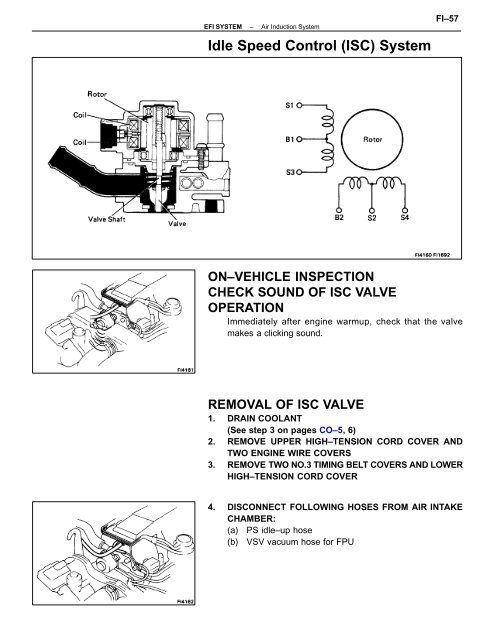
EFI SYSTEM – Air Induction <strong>System</strong><strong>Idle</strong> <strong>Speed</strong> <strong>Control</strong> (<strong>ISC</strong>) <strong>System</strong>FI–57ON–VEHICLE INSPECTIONCHECK SOUND OF <strong>ISC</strong> VALVEOPERATIONImmediately after engine warmup, check that the valvemakes a clicking sound.REMOVAL OF <strong>ISC</strong> VALVE1. DRAIN COOLANT(See step 3 on pages CO–5, 6)2. REMOVE UPPER HIGH–TENSION CORD COVER ANDTWO ENGINE WIRE COVERS3. REMOVE TWO NO.3 TIMING BELT COVERS AND LOWERHIGH–TENSION CORD COVER4. D<strong>ISC</strong>ONNECT FOLLOWING HOSES FROM AIR INTAKECHAMBER:(a) PS idle–up hose(b) VSV vacuum hose for FPU
FI–58EFI SYSTEM–Air Induction <strong>System</strong>5. REMOVE <strong>ISC</strong> AIR HOSE6. D<strong>ISC</strong>ONNECT FOLLOWING HOSES FROM <strong>ISC</strong> VALVE:(a) No.4 water by–pass pipe(b) No.5 water by–pass pipe7. D<strong>ISC</strong>ONNECT <strong>ISC</strong> VALVE CONNECTOR8. REMOVE <strong>ISC</strong> VALVE(a) Remove the two nuts, and remove the <strong>ISC</strong> valve andgasket.(b) Disconnect the water hose from the water inlet housing.9. D<strong>ISC</strong>ONNECT TWO WATER HOSESDisconnect the two water hoses from the <strong>ISC</strong> valve.
EFI SYSTEM – Air Induction <strong>System</strong>FI–59INSPECTION OF <strong>ISC</strong> VALVE1. CHECK <strong>ISC</strong> VALVE OPERATIONUsing an ohmmeter, measure the resistance between eachpair of terminals.Resistance: B1–S1 (S3) 10–30 B2–S2 (S4) 10–30 If the resistance is not as specified, replace the <strong>ISC</strong> valve.2. CHECK <strong>ISC</strong> VALVE OPERATION(a) Connect the battery positive terminal to terminal B1 andB2, and connect the negative terminal to terminals S1S2 S3 S4 in that order, and check that the valve movesin the closed direction.(b) Connect the battery positive terminal to terminals B1and B2, and connect the negative terminal to terminalsS4 S3 S2 S1 in that order, and check that the valvemoves in the open direction.If the <strong>ISC</strong> valve does not operate as specified, replace <strong>ISC</strong>valve.
FI–60EFI SYSTEM–Air Induction <strong>System</strong>INSTALLATION OF <strong>ISC</strong> VALVE1. INSTALL TWO WATER HOSES2. INSTALL <strong>ISC</strong> VALVE(a) Install a new gasket to the air intake chamber.(b) Connect the water hose to the water inlet housing.(c) Install the <strong>ISC</strong> valve with two nuts.Torque: 185 kg–cm (13 ft–lb, 18 N⋅m)3. CONNECT <strong>ISC</strong> VALVE CONNECTOR4. CONNECT FOLLOWING HOSES TO <strong>ISC</strong> VALVE:(a) No.5 water by–pass pipe(b) No.4 water by–pass pipe5. CONNECT <strong>ISC</strong> AIR HOSE6. CONNECT FOLLOWING HOSES TO AIR INTAKECHAMBER:(a) VSV vacuum hose for FPU(b) PS idle–up hose7. INSTALL LOWER HIGH–TENSION CORD COVER ANDTWO NO.3 TIMING BELT COVERS8. INSTALL TWO ENGINE WIRE COVERS AND UPPERHIGHTENSION CORD COVER9. FILL WITH COOLANT(See step 3 on pages CO–5, 6)10. CHECK FOR COOLANT LEAKAGEStart the engine and check for coolant leakage.11. CHECK COOLANT LEVEL(See step 1 on page CO–5)

![16 RELAY LOCATIONS [Engine Compartment] [Body] - Lextreme.com](https://img.yumpu.com/46854657/1/190x245/16-relay-locations-engine-compartment-body-lextremecom.jpg?quality=85)