J3UZ-FE ENGINE 1. General - Lextreme.com
J3UZ-FE ENGINE 1. General - Lextreme.com
J3UZ-FE ENGINE 1. General - Lextreme.com

Create successful ePaper yourself
Turn your PDF publications into a flip-book with our unique Google optimized e-Paper software.
8<br />
�3UZ-<strong>FE</strong> <strong>ENGINE</strong><br />
<strong>1.</strong> <strong>General</strong><br />
GS430/300 — NEW <strong>FE</strong>ATURES<br />
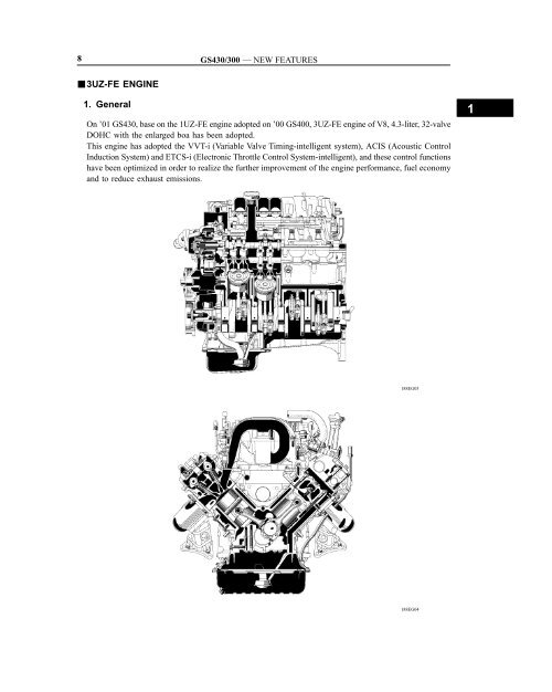
On ’01 GS430, base on the 1UZ-<strong>FE</strong> engine adopted on ’00 GS400, 3UZ-<strong>FE</strong> engine of V8, 4.3-liter, 32-valve<br />
DOHC with the enlarged boa has been adopted.<br />
This engine has adopted the VVT-i (Variable Valve Timing-intelligent system), ACIS (Acoustic Control<br />
Induction System) and ETCS-i (Electronic Throttle Control System-intelligent), and these control functions<br />
have been optimized in order to realize the further improvement of the engine performance, fuel economy<br />
and to reduce exhaust emissions.<br />
188EG03<br />
188EG04<br />
1
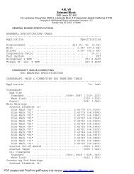
� Engine Specifications �<br />
GS430/300 — NEW <strong>FE</strong>ATURES<br />
Engine Type 3UZ-<strong>FE</strong> 1UZ-<strong>FE</strong><br />
No. of Cyls. & Arrangement 8-Cylinder, V Type �<br />
Valve Mechanism<br />
32 Valve DOHC, Belt &<br />
Gear Drive<br />
�<br />
Combustion Chamber Pentroof Type �<br />
Manifolds Cross-Flow �<br />
Fuel System SFI �<br />
Displacement cm3 (cu. in.) 4293 (26<strong>1.</strong>9) 3969 (242.1)<br />
Bore � Stroke mm (in.) 9<strong>1.</strong>0 × 82.5 (3.58 × 3.25) 87.5 × 82.5 (3.44 × 3.25)<br />
Compression Ratio 10.5 : 1 �<br />
Max. Output [SAE-NET]<br />
Max. Torque [SAE-NET]<br />
Valve Timing<br />
Intake<br />
223.4 kW @ 5600 rpm<br />
(300 HP @ 5600 rpm)<br />
440 N⋅m @ 3400 rpm<br />
(325 ft⋅lbf @ 3400 rpm)<br />
�<br />
420 N⋅m @ 4000 rpm<br />
(310 ft⋅lbf @ 4000 rpm)<br />
Open –14° ~ 31° BTDC –14° ~ 36° BTDC<br />
Close 64° ~ 19° ABDC 64° ~ 14° ABDC<br />
Open 46° BBDC �<br />
Exhaust<br />
Close 3° ATDC �<br />
Fuel Octane Number RON 95 or more 96<br />
Oil Grade API SJ, EC or ILSAC �<br />
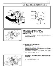
� Performance Curve �<br />
Torque<br />
N·m ft-lbf<br />
460<br />
440<br />
420<br />
400<br />
380<br />
360<br />
340<br />
320<br />
300<br />
340<br />
320<br />
300<br />
280<br />
260<br />
240<br />
220<br />
: ’01 GS430<br />
: ’00 GS400<br />
1000 2000 3000 4000 5000 6000 7000<br />
Engine Speed (rpm)<br />
HP kW<br />
320<br />
300<br />
280<br />
260<br />
240<br />
220<br />
200<br />
180<br />
160<br />
140<br />
120<br />
100<br />
80<br />
60<br />
40<br />
20<br />
240<br />
220<br />
200<br />
180<br />
160<br />
140<br />
120<br />
100<br />
80<br />
60<br />
40<br />
20<br />
0<br />
186EG03<br />
9
10<br />
2. Major Differences<br />
GS430/300 — NEW <strong>FE</strong>ATURES<br />
The major differences between the 3UZ-<strong>FE</strong> on the ’01 GS430 and the 1UZ-<strong>FE</strong> engine on the ’00 GS400<br />
are the following:<br />
System Features<br />
• The water passage of the cylinder head has been changed to improve<br />
the flow of the water around the valve seats, thus reducing<br />
the temperature of the <strong>com</strong>bustion chamber.<br />
• The cylinder bore has been increased in size, and the thickness of<br />
the liner has been reduced.<br />
• The shape of the cylinder head gasket has been changed in conjunction<br />
with the increase in the size of the cylinder bore.<br />
• The material of the cylinder head bolts have been changed to in-<br />
Engine Proper<br />
crease their axial tension. As a result, the head gasket’s tightening<br />
has been improved.<br />
• The piston diameter has been increased in size, and its shape has<br />
been optimized to achieve weight reduction.<br />
• The material of the inner surface of the bushing in the small end<br />
of the connecting rod has been changed from lead bronze alloy to<br />
phosphor bronze alloy.<br />
• The material of the sliding surface of the crankshaft bearing has<br />
been changed from kelmet to aluminum alloy.<br />
The shape of the water inlet housing has been optimized to increase<br />
Cooling System<br />
the water flow and to achieve weight reduction.<br />
• A resonator and a tuning hole have been provided in the air cleaner<br />
inlet to reduce the amount of intake air noise.<br />
• The air cleaner case has been increased in size to reduce the<br />
amount of intake air sound, and the construction of the air cleaner<br />
element has been optimized to achieve weight reduction.<br />
• A plug-in type air flow meter with a plastic housing has been<br />
adopted for weight reduction.<br />
Intake and Exhaust System<br />
• A stainless steel exhaust manifold with a single-pipe construction<br />
has been adopted. As a result, the warm-up performance of the<br />
TWC (Three-way Catalytic Converter) has been improved.<br />
• Two TWCs (Three-way Catalytic Converters) have been provided<br />
in the front, and one in the center.<br />
• Ultra thin-wall, high-cell ceramic type TWCs have been adopted.<br />
• A link-less type throttle body has been adopted.<br />
Ignition System<br />
Engine Control System<br />
The construction of the ignition coil has been optimized to achieve a<br />
<strong>com</strong>pact and lightweight configuration.<br />
• Torque activated power train control has been newly adopted for<br />
the control of ETCS-i. Also, the fail-safe control has been reconsidered<br />
with the adoption of the link-less type throttle body.<br />
• A fuel cut control is adopted to stop the fuel pump when SRS driver’s<br />
and front passenger’s airbags are deployed.<br />
1
3. Engine Proper<br />
Cylinder Head<br />
GS430/300 — NEW <strong>FE</strong>ATURES<br />
� The cylinder head is made of aluminum and has intake and exhaust ports in a cross-flow arrangement.<br />
The intake ports are on the inside and the exhaust ports on the outside of the left and right banks respectively.<br />
� The pitch of the intake and exhaust camshafts is shortened and the valve angle is narrowed to 21° 33’.<br />
� The left and right banks of cylinder heads are <strong>com</strong>mon in configuration.<br />
NOTICE<br />
When the cylinder heads are disassembled for servicing, be sure to assemble each cylinder head<br />
to the correct right or left bank. The camshaft may seize if they are assembled incorrectly.<br />
Cylinder Head Gasket<br />
Intake<br />
Side<br />
21° 33’<br />
Valve Angle<br />
Exhaust<br />
Side<br />
The same type of (4-layer) steel laminate cylinder head gasket used in the 1UZ-<strong>FE</strong> engine on the ’00<br />
GS400 is used in the 3UZ-<strong>FE</strong> engine on the ’01 GS430, except that its shape has been slightly changed<br />
in accordance with the increased cylinder displacement of the new engine.<br />
A A<br />
Bead Plate<br />
Inner Plate<br />
A – A Cross Section<br />
188EG05<br />
Cylinder<br />
Bore Side<br />
151EG71<br />
11
12<br />
Cylinder Block<br />
GS430/300 — NEW <strong>FE</strong>ATURES<br />
� The cylinder block has a bank angle of 90°, a bore offset of 21 mm (0.827 in.) and a bore pitch of 105.5<br />
mm (4.15 in.), resulting in a <strong>com</strong>pact block in its length and width even for its displacement.<br />
� Light weight aluminum alloy is used for the cylinder block.<br />
� In contrast to the 1UZ-<strong>FE</strong> engine on the ’00 GS400, the liner thickness in the 3UZ-<strong>FE</strong> engine on the ’01<br />
GS430 has been changed from 2 mm (0.08 in.) to <strong>1.</strong>5 mm (0.06 in.) to achieve weight reduction and improved<br />
cooling performance. It is not possible to bore this liner due to its thinness. The thickness of the<br />
wall has been changed from 5.5 mm (0.22 in.) to 6.5 mm (0.26 in.), and the shape of the water passage<br />
between the bores has been optimized to improve both cooling performance and rigidity.<br />
Front<br />
Bank Angle<br />
90°<br />
<strong>1.</strong>5 mm<br />
(0.06 in.)<br />
6.5 mm<br />
(0.26 in.)<br />
Front<br />
Bore Offset<br />
2<strong>1.</strong>0 mm (0.827 in.)<br />
Bore Pitch<br />
105.4 mm (4.15 in.)<br />
5.5 mm<br />
(0.22 in.)<br />
3UZ-<strong>FE</strong> 1UZ-<strong>FE</strong><br />
2.0 mm<br />
(0.08 in.)<br />
A A<br />
A – A Cross Section<br />
188EG09<br />
Top View<br />
188EG10<br />
1
Piston<br />
GS430/300 — NEW <strong>FE</strong>ATURES<br />
� The piston head portion has adopted a taper squish shape to improve the fuel <strong>com</strong>bustion efficiency.<br />
� The sliding surface of the piston skirt has been coated with resin to reduce the amount of friction loss.<br />
� Full floating type piston pins are used.<br />
� By increasing the machining precision of the cylinder bore diameter, the outer diameter of the piston has<br />
been made into one type.<br />
� In contrast to the 1UZ-<strong>FE</strong> engine on the ’00 GS400, the placement position of the piston rings has been<br />
slightly raised in the 3UZ-<strong>FE</strong> engine on the ’01 GS430 in order to reduce the area in which unburned<br />
fuel is likely to accumulate during the <strong>com</strong>bustion process. Furthermore, the squish area in the thrust<br />
direction of the piston head has been discontinued and the <strong>com</strong>bustion chamber has been made shallower<br />
in order to further improve the <strong>com</strong>bustion efficiency, thus improving fuel economy.<br />
Squish area<br />
discontinued<br />
3UZ-<strong>FE</strong><br />
0.5 mm<br />
(0.02 in)<br />
3UZ-<strong>FE</strong> 1UZ-<strong>FE</strong><br />
188EG11<br />
1UZ-<strong>FE</strong><br />
188EG12<br />
13
14<br />
Connecting Rod<br />
GS430/300 — NEW <strong>FE</strong>ATURES<br />
� The sintered and forged connecting rod is highly<br />
rigid and has little weight fluctuation.<br />
� A weight-adjusting boss is provided at the big<br />
end to reduce fluctuation of weight and balance<br />
the engine assembly.<br />
� In contrast to the 1UZ-<strong>FE</strong> engine on the ’00<br />
GS400, the material of the inner surface of the<br />
bushing in the small end of the connecting rod in<br />
the 3UZ-<strong>FE</strong> engine on the ’01 GS430 has been<br />
changed from lead bronze alloy to phosphor<br />
bronze alloy to reduce the lead quantity and to<br />
further improve the wear resistance.<br />
� The connecting rod cap is held by plastic region<br />
tightening bolts.<br />
NOTE: When reusing the connecting rod cap bolts,<br />
if the diameter at the thread is less than 7.0<br />
mm (0.275 in.), it is necessary to replace<br />
them with new ones.<br />
� The connecting rods for the right and left banks<br />
are placed in opposite directions with the outer<br />
marks facing the crankshaft.<br />
Front<br />
Oil Jet Nozzle<br />
Outer Mark<br />
Left Bank<br />
Connecting Rod<br />
Phosphor<br />
Bronze<br />
188EG13<br />
Weight Adjusting Boss<br />
Plastic Region Tightening Bolt<br />
Outer Marks (projected)<br />
188EG14<br />
Right Bank<br />
Connecting<br />
Rod<br />
Crankshaft<br />
188EG15<br />
1
Crankshaft and Crankshaft Bearings<br />
GS430/300 — NEW <strong>FE</strong>ATURES<br />
� A forged crankshaft with five main journals, four connecting rod pins and eight balance weight is used.<br />
� Connecting rod pins and journals are induction-hardened to ensure an added reliability.<br />
� In contrast to the 1UZ-<strong>FE</strong> engine on the ’00 GS400, the material of the sliding surface of the crankshaft<br />
bearing in the 3UZ-<strong>FE</strong> engine on the ’01 GS430 has been changed from kelmet to aluminum alloy to<br />
discontinue the use of lead and to further enhance the engine’s quiet operation.<br />
� Crankshaft bearings are selected carefully according to the measured diameters of the crank journal and<br />
cylinder block journal holes.<br />
NOTE: The diameter of the crank journal and the cylinder block journal hole is indicated at the places<br />
shown below.<br />
No. 5 Journal<br />
Front Front<br />
Journal diameters for No. 1-5 journals<br />
are indicated from the front end in order.<br />
188EG17<br />
188EG16<br />
Journal hole diameters for No. 1-5<br />
journals are indicated.<br />
Bottom view of the cylinder block<br />
188EG18<br />
15
16<br />
GS430/300 — NEW <strong>FE</strong>ATURES<br />
NOTE: Numbers of the crankshaft and pistons are<br />
shown on the right side.<br />
Front<br />
Front<br />
No. 8<br />
Cylinder<br />
No. 6<br />
Cylinder<br />
No. 4<br />
Cylinder<br />
No. 2<br />
Cylinder<br />
No. 1, 2 No. 3, 4 No. 5, 6 No. 7, 8<br />
Right Bank Left Bank<br />
No. 1, 2<br />
No. 5, 6<br />
Bank Angle<br />
90°<br />
Pin Position<br />
No. 3, 4<br />
No. 7, 8<br />
No. 7<br />
Cylinder<br />
No. 5<br />
Cylinder<br />
No. 3<br />
Cylinder<br />
No. 1<br />
Cylinder<br />
Crankshaft angles and engine strokes (intake, <strong>com</strong>pression, <strong>com</strong>bustion and exhaust) are shown in the<br />
table below. The firing order is 1 - 8 - 4- 3 - 6 - 5 - 7 - 2.<br />
Cylinder<br />
No. 1<br />
No. 8<br />
No. 4<br />
No. 3<br />
No. 6<br />
No. 5<br />
No. 7<br />
No. 2<br />
Injection<br />
0° 180° 360° 540°<br />
Crankshaft Angle<br />
Ignition<br />
Combustion Exhaust Intake Compression Combustion Exhaust<br />
720°<br />
TDC<br />
BDC<br />
188EG20<br />
188EG19<br />
1
4. Valve Mechanism<br />
<strong>General</strong><br />
GS430/300 — NEW <strong>FE</strong>ATURES<br />
� Each cylinder has 2 intake valves and 2 exhaust valves. Intake and exhaust efficiency has been increased<br />
due to the larger total port areas.<br />
� The valves are directly opened and closed by 4 camshafts.<br />
� The intake camshafts are driven by a timing belt, while the exhaust camshaft are driven through gears<br />
on the intake camshafts.<br />
� The VVT-i (Variable Valve Timing-intelligent) system is used to improve fuel economy,engine performance<br />
and reduce exhaust emissions. For details, see page 42.<br />
� In contrast to the 1UZ-<strong>FE</strong> engine on the ’00 GS400, an automatic timing belt tensioner with optimized<br />
construction and body material that has been changed to aluminum has been adopted in the 3UZ-<strong>FE</strong> engine<br />
on the ’01 GS430.<br />
Camshaft Timing<br />
Oil Control Valves<br />
VVT-i Controller<br />
Camshaft<br />
Position<br />
Sensor<br />
VVT Sensors<br />
Exhaust<br />
Valves<br />
Exhaust Camshaft<br />
Intake<br />
Valves<br />
VVT-i Controller<br />
Intake Camshafts<br />
Intake Valves<br />
Exhaust Camshaft<br />
Exhaust Valves<br />
188EG21<br />
17
18<br />
Camshafts<br />
GS430/300 — NEW <strong>FE</strong>ATURES<br />
� The exhaust camshafts are driven by gears on the intake camshafts. The scissors gear mechanism has<br />
been used on the exhaust camshaft to control backlash and reduce gear noise.<br />
� A VVT-i controllers have been installed on the front of the intake camshafts to vary the timing of the<br />
intake valves.<br />
� In conjunction with the adoption of the VVT-i system, an oil passage is provided in the intake camshaft<br />
in order to supply engine oil to the VVT-i system.<br />
� The intake camshaft is provided with timing rotor to trigger the VVT sensor.<br />
Retard Side Oil Passage<br />
Exhaust Camshaft<br />
Camshaft Driven Gear<br />
(Scissors Gear)<br />
Advance Side Oil Passage<br />
VVT-i Controllers<br />
Camshaft Drive Gears<br />
A<br />
A<br />
Camshaft Driven Gear<br />
(Scissors Gear)<br />
Timing Rotor<br />
151EG24<br />
Timing Rotors<br />
151EG25<br />
A – A Cross Section<br />
Exhaust Camshaft<br />
Intake Camshafts<br />
188EG22<br />
1
Camshaft<br />
Valve<br />
Adjusting<br />
Shim<br />
Valve Lifter<br />
Valve<br />
GS430/300 — NEW <strong>FE</strong>ATURES<br />
Intake and Exhaust Valve and Valve Lifter<br />
� An inner shim type valve adjusting shim has been adopted as well as the 1UZ-<strong>FE</strong> engine of ’00 GS400.<br />
� The valve lifter, which has been made lighter and thinner.<br />
� High-strength, heat-resistant steel is used in both the intake and exhaust valves, and soft nitriding treatment<br />
has been applied to the stem and the face areas of the valves.<br />
� Carbon steel with a round-shaped cross section has been adopted for the valve spring, which is used for<br />
both the intake and exhaust valves.<br />
188EG63<br />
Timing Pulleys, Automatic Tensioner and Timing Belt Cover<br />
19<br />
� Specifications � mm (in.)<br />
Item Intake Valve<br />
Exhaust<br />
Valve<br />
Face<br />
Diameter<br />
34.5 (<strong>1.</strong>36) 29.0 (<strong>1.</strong>14)<br />
Stem<br />
Diameter<br />
5.5 (0.22) 5.5 (0.22)<br />
� In contrast to the 1UZ-<strong>FE</strong> engine on the ’00 GS400, an automatic timing belt tensioner with optimized<br />
construction and body material that has been changed to aluminum has been adopted in the 3UZ-<strong>FE</strong> engine<br />
on the ’01 GS430.<br />
� The timing belt cover No. 3 is made of aluminum to reduce noise.<br />
� The timing belt cover No. 1 and No. 2 are <strong>com</strong>posite formed with a gasket to improve serviceability.<br />
Timing Belt Cover No. 3<br />
Right Bank<br />
Camshaft<br />
Timing<br />
Pulley<br />
Water Pump Pulley Left Bank<br />
Camshaft<br />
Timing<br />
Pulley<br />
Air<br />
Set Pin<br />
Piston<br />
Rod<br />
Cylinder Body<br />
(Aluminum)<br />
Return<br />
Spring<br />
Timing Belt<br />
Cover No. 2<br />
Timing Belt<br />
Cover No. 1<br />
188EG23<br />
Belt Idler<br />
Automatic Tensioner<br />
188EG24<br />
Belt Idler<br />
Crank Shaft<br />
Timing Pulley<br />
Oil<br />
Plunger<br />
Plunger<br />
Spring<br />
Sleeve<br />
Automatic Tensioner<br />
188EG25
20<br />
5. Lubrication System<br />
GS430/300 — NEW <strong>FE</strong>ATURES<br />
� The lubrication circuit is fully pressurized and oil passes through an oil filter.<br />
� The trochoid gear type oil pump is directly driven by the crankshaft.<br />
� Along with the adoption of the VVT-i (Variable Valve Timing-intelligent), right bank and left bank cylinder<br />
heads are provided with VVT-i controllers and camshaft timing oil control valves. This system is<br />
operated by the engine oil.<br />
BYPASS<br />
VALVE<br />
RELIEF<br />
VALVE<br />
VVT-i Controllers<br />
OIL FILTER<br />
OIL PUMP<br />
OIL<br />
STRAINER<br />
Camshaft Timing<br />
Oil Control Valves<br />
CYLINDER HEAD<br />
(FOR LEFT BANK)<br />
EXHAUST<br />
CAMSHAFT<br />
JOURNALS<br />
Oil Pump<br />
SCISSORS GEAR<br />
MECHANISM<br />
INTAKE<br />
CAMSHAFT<br />
JOURNALS<br />
MAIN OIL HOLE<br />
CAMSHAFT TIMING<br />
OIL CONTROL<br />
VALVE FILTER<br />
(FOR LEFT BANK)<br />
CAMSHAFT TIMING<br />
OIL CONTROL VALVE<br />
(FOR LEFT BANK)<br />
VVT-i<br />
CONTROLLER<br />
(FOR LEFT<br />
BANK)<br />
OIL PAN<br />
CRANKSHAFT<br />
JOURNALS<br />
CRANKSHAFT<br />
PINS<br />
OIL JETS<br />
PISTONS<br />
188EG26<br />
CAMSHAFT TIMING<br />
OIL CONTROL<br />
VALVE FILTER<br />
(FOR RIGHT BANK)<br />
CAMSHAFT TIMING<br />
OIL CONTROL VALVE<br />
(FOR RIGHT BANK)<br />
VVT-i<br />
CONTROLLER<br />
(FOR RIGHT<br />
BANK)<br />
CYLINDER HEAD<br />
(FOR RIGHT BANK)<br />
INTAKE<br />
CAMSHAFT<br />
JOURNALS<br />
EXHAUST<br />
CAMSHAFT<br />
JOURNALS<br />
SCISSORS GEAR<br />
MECHANISM<br />
188EG27<br />
1
6. Cooling System<br />
<strong>General</strong><br />
GS430/300 — NEW <strong>FE</strong>ATURES<br />
� The cooling system is a pressurized, forced-circulation type.<br />
� A thermostat, having a by-pass valve, is located on the water pump inlet side of the cooling circuit. As<br />
the coolant temperature rises, the thermostat opens and the by-pass valve closes, so the system maintains<br />
suitable temperature distribution in the cylinder head.<br />
� In contrast to the 1UZ-<strong>FE</strong> engine on the ’00 GS400, the shape of the water inlet housing has been optimized<br />
in the 3UZ-<strong>FE</strong> engine on the ’01 GS430 to achieve the smooth flow of the engine coolant.<br />
Reservoit<br />
Tank<br />
Radiator<br />
Throttle Body<br />
Thermostat<br />
Cylinder Head<br />
Cylinder Block<br />
Water Pump<br />
Heater Core<br />
From Heater Core<br />
To Heater Core<br />
188EG28<br />
186EG06<br />
21
22<br />
Water Pump<br />
GS430/300 — NEW <strong>FE</strong>ATURES<br />
� The water pump has two volute chambers, and<br />
circulates coolant uniformly to the left and right<br />
banks of the cylinder block.<br />
� The water pump is driven by the back surface of<br />
the timing belt.<br />
� The rotor is made of resin.<br />
Water Inlet Housing<br />
Rotor<br />
From Water<br />
Inlet Housing<br />
Pulley<br />
Volute<br />
Chambers<br />
Rotor<br />
In contrast to the 1UZ-<strong>FE</strong> engine on the ’00 GS400, the shape of the water inlet housing has been optimized<br />
in the 3UZ-<strong>FE</strong> engine on the ’01 GS430 to achieve the smooth flow of the engine coolant.<br />
Flow of Water<br />
3UZ-<strong>FE</strong> Engine 1UZ-<strong>FE</strong> Engine<br />
188EG32<br />
188EG33<br />
188EG30<br />
1
Cooling Fan System<br />
GS430/300 — NEW <strong>FE</strong>ATURES<br />
The same electric cooling fan system used on the ’00 GS400 has been adopted on the ’01 GS430. The<br />
cooling fan controls the fan speed in 3 steps (OFF, Low, High) by using the water temperature switch<br />
in accordance with the engine coolant temperature and the operating condition of the air conditioner and<br />
by turning the 3 fan relays ON and OFF and connecting 2 fan motors in a series or parallel circuit.<br />
� Wiring Diagram �<br />
Battery<br />
Ignition<br />
Switch<br />
Condenser<br />
Fan Motor<br />
Fan No. 2<br />
Relay<br />
To A/C<br />
Magnetic<br />
Clutch Relay<br />
Fan No. 3<br />
Relay<br />
� Cooling Fan Operation �<br />
Fan Main<br />
Relay<br />
Fan No. 1<br />
Relay<br />
Radiator<br />
Fan Motor<br />
<strong>1.</strong>2 MPa<br />
(12.5 kgf/cm 2 ) ON<br />
OFF<br />
<strong>1.</strong>5 MPa<br />
(15.5 kgf/cm2 )<br />
A/C Pressure Switch<br />
Water Temp. Switch<br />
83°C<br />
(181°F) ON<br />
Air Conditioner Condition Water Temperature<br />
Compressor Refrigerant Pressure<br />
About 83°C (181°F)<br />
or Lower<br />
OFF<br />
90°C<br />
(194°F)<br />
188EG60<br />
About 90°C (194°F)<br />
or Higher<br />
OFF <strong>1.</strong>2 MPa (12.5 kgf/cm2 ) or Lower OFF High<br />
ON<br />
<strong>1.</strong>2 MPa (12.5 kgf/cm2 ON<br />
) or Lower<br />
<strong>1.</strong>5 MPa (15.5 kgf/cm<br />
Low High<br />
2 ) or Higher High High<br />
23
24<br />
7. Intake and Exhaust System<br />
GS430/300 — NEW <strong>FE</strong>ATURES<br />
Air Cleaner Inlet Pipe, Box and Air Connector<br />
� A resonator and a tuning hole have been provided in the air cleaner inlet to reduce the amount of intake<br />
air noise.<br />
� The air cleaner case has been increased in size to reduce the amount of intake air noise, and the construction<br />
of the air cleaner element has been optimized to achieve weight reduction.<br />
Air Cleaner<br />
Cap<br />
Air<br />
Cleaner<br />
Element<br />
Air Cleaner<br />
Case<br />
Intake Manifold<br />
Resonator<br />
Intake Air Connector Pipe<br />
Air Cleaner<br />
Inlet<br />
Tuning Hole<br />
Back Side View<br />
Resonator<br />
� The low-to mid-speed range torque has been improved by increasing the length of the intake manifold<br />
port.<br />
� The air intake chamber consists of upper and lower sections and contains an intake air control valve. This<br />
valve is activated by ACIS (Acoustic Control Induction System) and is used to alter the intake pipe length<br />
to improve the engine performance in all speed ranges. For details, see page 53.<br />
Intake Air Control Valve<br />
Actuator<br />
(for ACIS)<br />
Front<br />
188EG34<br />
188EG35<br />
1
Intake Manifold Gasket<br />
Top View<br />
Side View<br />
GS430/300 — NEW <strong>FE</strong>ATURES<br />
� A heat-barrier gasket has been adopted for use between the cylinder head and the intake manifold. This<br />
gasket, which restrains the heat transfer from the cylinder head to the intake manifold, helps restrain the<br />
intake air temperature and improve the charging efficiency.<br />
� The construction of the gasket consists of resin that is sandwiched between metal gaskets.<br />
A<br />
Exhaust Manifold<br />
A<br />
Top View<br />
Side View<br />
Front<br />
188EG36<br />
151EG69<br />
Cooling<br />
Holes<br />
Front<br />
Cooling<br />
Holes<br />
Front Front<br />
Resin<br />
A – A Cross Section<br />
Top View<br />
Side View<br />
Top View<br />
Side View<br />
188EG37<br />
188EG38 188EG39<br />
Metal Gasket<br />
� The front exhaust pipe has been shortened and the warm-up performance of the TWC (Three-Way Catalytic<br />
Converter) has been improved.<br />
144EG04<br />
� Cooling holes have been provided in the heat insulator for cooling the exhaust manifold.<br />
� Right-Hand Exhaust Manifold � � Left-Hand Exhaust Manifold �<br />
� Right-Hand Heat Insulator � � Left-Hand Heat Insulator �<br />
25
26<br />
Exhaust Pipe<br />
GS430/300 — NEW <strong>FE</strong>ATURES<br />
Two TWCs (Three-way Catalytic Converters) have been provided in the front, and one in the center.<br />
Three-Way Catalytic Converter<br />
TWCs<br />
TWC<br />
An ultra thin-wall, high-cell ceramic type TWC has been adopted. This TWC enables to optimize the<br />
cells density and to reduce wall thickness. In addition, it enables to achieve cleaner exhaust emission<br />
by double-coating the alumina material on the ceramic surface.<br />
Wall Thickness<br />
188EG40<br />
189EG21<br />
1
8. Fuel System<br />
<strong>General</strong><br />
GS430/300 — NEW <strong>FE</strong>ATURES<br />
� A fuel returnless system has been used to simplify the routing of the fuel pipe.<br />
� An air-assist system has been adopted to improve the atomization of fuel, thus improving the performance<br />
of the evaporative emissions.<br />
� A <strong>com</strong>pact 4-hole type fuel injector has been used.<br />
Fuel Returnless System<br />
� The fuel returnless system has been used to reduce evaporative emissions. With the pressure regulator<br />
and the fuel filter-integrated fuel pump are housed inside the fuel tank, this system eliminates the return<br />
of fuel from the engine area. This helps prevent the internal temperature of the fuel tank from rising, and<br />
reduces evaporative emissions.<br />
� 2 pulsation dampers are used to realize a quieter operation.<br />
Delivery Pipes<br />
Pulsation Damper<br />
Fuel Filter<br />
Fuel Pump<br />
Injectors<br />
Pressure<br />
Regulator Fuel Tank<br />
Module Fuel<br />
Pump Assembly<br />
Jet Pump<br />
Pulsation Damper<br />
189EG05<br />
27
28<br />
Air Assist System<br />
GS430/300 — NEW <strong>FE</strong>ATURES<br />
This system is designed to regulate air intake (atmospheric side) using the throttle valve, and direct it<br />
to the nozzle of the fuel injector inside the intake manifold (negative pressure side). This promotes atomization<br />
of the fuel while reducing emissions and improving fuel economy and idle stability.<br />
Throttle Valve<br />
Fuel Injector<br />
Throttle Body<br />
Air Passage<br />
� A <strong>com</strong>pact 4-hole type fuel injector has been<br />
used.<br />
� Air introduced from the throttle body and air gallery<br />
flows through the air chamber formed by the<br />
o-ring and insulator under the fuel injector and<br />
then is mixed with the fuel. This design promotes<br />
atomization of the fuel.<br />
Injector<br />
O-Ring<br />
151EG35<br />
Insulator<br />
Air Gallery<br />
151EG36<br />
1
Module Fuel Pump Assembly<br />
GS430/300 — NEW <strong>FE</strong>ATURES<br />
The main sender gauge, fuel pump, fuel filter, pressure<br />
regulator and jet pump have been integrated.<br />
Jet Pump<br />
Main Sender<br />
Gauge<br />
Fuel Filter<br />
Jet Pump<br />
Pressure<br />
Regulator<br />
Fuel Pump<br />
A jet pump is adopted in the fuel tank. Since the propeller shaft is located below its center bottom, the<br />
fuel tank of the GS430 is shaped as indicated below.<br />
A fuel tank with such a shape tends to cause the fuel to be dispersed into both chamber A and chamber<br />
B when the fuel level is low, stopping the fuel in chamber B from being pumped out. To prevent this<br />
from occurring, a jet pump has been provided to transfer the fuel from chamber B to chamber A.<br />
This is ac<strong>com</strong>plished by utilizing the flow of the fuel, so that the vacuum created by the fuel, as it passes<br />
through the venturi is used to suck the fuel out of chamber B and send it to chamber A.<br />
Fuel Filter<br />
Fuel<br />
Pump<br />
Pressure Regulator<br />
Jet Pump<br />
Engine<br />
Chamber A Chamber B<br />
152EG06<br />
From Chamber B<br />
To Chamber A<br />
Jet Pump<br />
From Fuel<br />
Pump<br />
152EG07<br />
163EG35<br />
29
30<br />
9. Ignition System<br />
<strong>General</strong><br />
GS430/300 — NEW <strong>FE</strong>ATURES<br />
� A DIS (Direct Ignition System) has been adopted. The DIS improves the ignition timing accuracy, reduces<br />
high-voltage loss, and enhances the overall reliability of the ignition system by eliminating the<br />
distributor.<br />
The DIS in this engine is an independent ignition system which has one ignition coil (with igniter) for<br />
each cylinder.<br />
� Iridium-tipped spark plugs have been adopted.<br />
� In contrast to the 1UZ-<strong>FE</strong> engine on the ’00 GS400, <strong>com</strong>pact and lightweight ignition coils with an optimized<br />
construction have been adopted in the 3UZ-<strong>FE</strong> engine on the ’01 GS430.<br />
Camshaft<br />
Position<br />
Sensor<br />
Crankshaft<br />
Position<br />
Sensor<br />
Various<br />
Sensors<br />
G2<br />
NE<br />
ECM<br />
IGT 1<br />
IGT 2<br />
IGT 3<br />
IGT 4<br />
IGT 5<br />
IGT 6<br />
IGT 7<br />
IGT 8<br />
IF 1L<br />
IF 2R<br />
IF 1R<br />
IF 2L<br />
+B<br />
Ignition Coil (With Igniter)<br />
No. 1 Cylinder<br />
No. 2 Cylinder<br />
No. 3 Cylinder<br />
No. 4 Cylinder<br />
No. 5 Cylinder<br />
No. 6 Cylinder<br />
No. 7 Cylinder<br />
No. 8 Cylinder<br />
188EG62<br />
1
Spark Plug<br />
0.7 mm<br />
GS430/300 — NEW <strong>FE</strong>ATURES<br />
Iridium-tipped spark plugs have been adopted to realize a 120,000-mile (192,000 km) maintenance-free<br />
operation. Their center electrode is made of iridium, which excels in wear resistance. As a result, the<br />
center electrode is made with a smaller diameter and improved the ignition performance.<br />
Ignition Coil (with Igniter)<br />
Iridium Tip<br />
151EG39<br />
The DIS provides 8 ignition coils, one for each cylinder.<br />
The spark plug caps, which provide contact<br />
to the spark plugs, are integrated with an ignition<br />
coil. Also, an igniter is enclosed to simplify the system.<br />
However, in contrast to the 1UZ-<strong>FE</strong> engine<br />
on the ’00 GS400, <strong>com</strong>pact and lightweight ignition<br />
coils with an optimized construction have been<br />
adopted in the 3UZ-<strong>FE</strong> engine on the ’01 GS430.<br />
� Re<strong>com</strong>mended Spark Plugs �<br />
DENSO SK20R11<br />
NGK IFR6A11<br />
Plug Gap<br />
<strong>1.</strong>0 – <strong>1.</strong>1 mm<br />
(0.0394 – 0.043 in.)<br />
Plug Cap<br />
Igniter<br />
Iron Core<br />
Ignition Coil Cross Section<br />
188EG41<br />
31
32<br />
10. Serpentine Belt Drive System<br />
<strong>General</strong><br />
GS430/300 — NEW <strong>FE</strong>ATURES<br />
� Accessory <strong>com</strong>ponents are driven by a serpentine<br />
belt consisting of a single V-ribbed belt. It reduces<br />
the overall engine length, weight and number<br />
of engine parts.<br />
� An automatic tensioner eliminates the need for<br />
tension adjustment.<br />
Automatic Tensioner<br />
Idler Pulley<br />
(for Automatic<br />
Tensioner)<br />
Power<br />
Steering<br />
Pump<br />
Pulley<br />
Alternator<br />
Pulley<br />
Crankshaft<br />
Pulley<br />
Idler Pulley<br />
Idler Pulley<br />
Air<br />
Conditioning<br />
Compressor<br />
Pulley<br />
The automatic tensioner, which mainly consists of an idler pulley, an arm, a spring case, and a torsion<br />
spring, maintains the tension of the V-ribbed belt constant through the force of the torsion spring.<br />
Idler Pulley<br />
Arm<br />
Cross Section<br />
Torsion Spring<br />
Spring Case<br />
Rotating<br />
Direction<br />
Idler Pulley<br />
Spring Case<br />
188EG43<br />
188EG42<br />
Indicator<br />
Mark<br />
1
1<strong>1.</strong> Engine Control System<br />
<strong>General</strong><br />
GS430/300 — NEW <strong>FE</strong>ATURES<br />
The engine control system of the 3UZ-<strong>FE</strong> engine on the ’01 GS430 is basically same in construction<br />
and operation as that of the 1UZ-<strong>FE</strong> engine on the ’00 GS400.<br />
The engine control system of the 3UZ-<strong>FE</strong> engine and 1UZ-<strong>FE</strong> engine are <strong>com</strong>pared below.<br />
System Outline 3UZ-<strong>FE</strong> 1UZ-<strong>FE</strong><br />
SFI<br />
Electronic Fuel<br />
Injection<br />
ESA<br />
El Electronic t i SSpark k<br />
Advance<br />
VVT-i<br />
Variable Valve<br />
Timing-intelligent<br />
An L-type EFI system directly detects the intake air mass<br />
with a hot wire type air flow meter.<br />
� �<br />
Ignition timing is determined by the ECM based on signals<br />
from various sensors. The ECM corrects ignition timing<br />
in response to engine knocking.<br />
� �<br />
2 knock sensors are used to improve knock detection. � �<br />
The torque control correction during gear shifting has been<br />
used to minimize the shift shock.<br />
Controls the intake camshaft to an optimal valve timing in<br />
� �<br />
accordance with the engine condition. For details, see<br />
page 42.<br />
Optimally controls the throttle valve opening in accordance<br />
with the amount of accelerator pedal effort and the<br />
� �<br />
condition of the engine and the vehicle. In addition, <strong>com</strong>prehensively<br />
controls the IAC, snow mode control, cruise<br />
control, VSC system, and TRAC systems. For details, see<br />
page 47.<br />
� �<br />
ETCS-i<br />
Electronic<br />
Throttle Control<br />
System-intelligent Torque activated power train control has been adopted.<br />
Also, the fail-safe control has been reconsidered with the<br />
adoption of the link-less type throttle body.<br />
For details, see page 47.<br />
ACIS<br />
The intake air passages are switched according to the en-<br />
Acoustic Control gine speed and throttle valve angle to increase perfor-<br />
Induction System mance in all speed ranges. For details, see page 53.<br />
Fuel Pump Control<br />
Oxygen Sensor<br />
Heater Control<br />
Air Conditioning<br />
Cut-Off Control<br />
Under light engine loads, pump speed is low to reduce<br />
electric power loss.<br />
The fuel pump ECU controls the fuel pump speed in 3<br />
steps.<br />
The operation of the fuel pump will stop when the airbag<br />
is deployed at the front or side collision. For details, see<br />
page 56.<br />
Maintains the temperature of the oxygen sensor at an appropriate<br />
level to increase accuracy of detection of the oxygen<br />
concentration in the exhaust gas.<br />
By controlling the air conditioning <strong>com</strong>pressor ON or<br />
OFF in accordance with the engine condition, drivability<br />
is maintained.<br />
� —<br />
� �<br />
�� ��<br />
� —<br />
� �<br />
� �<br />
33<br />
(Continued)
34<br />
GS430/300 — NEW <strong>FE</strong>ATURES<br />
System Outline 3UZ-<strong>FE</strong> 1UZ-<strong>FE</strong><br />
Evaporative<br />
Emission Control<br />
Engine Immobiliser<br />
Function to<br />
<strong>com</strong>municate with<br />
multiplex <strong>com</strong>munication<br />
system<br />
Diagnosis<br />
Fail-Safe<br />
The ECM controls the purge flow of evaporative emissions<br />
(HC) in the charcoal canister in accordance with engine<br />
conditions.<br />
Using 3 VSVs and a vapor pressure sensor, the ECM detects<br />
any evaporative emission leakage occurring between<br />
the fuel tank and the charcoal canister through the changes<br />
in the tank pressure.<br />
Prohibits fuel delivery and ignition if an attempt is made<br />
to start the engine with an invalid ignition key.<br />
Communicates with the body ECU, A/C ECU, etc., on the<br />
body side, to input/output necessary signals.<br />
When the ECM detects a malfunction, the ECM diagnoses<br />
and memorizes the failed section.<br />
When the ECM detects a malfunction, the ECM stops or<br />
controls the engine according to the data already stored in<br />
the memory.<br />
� �<br />
� —<br />
� �<br />
� �<br />
� �<br />
� �<br />
1

![16 RELAY LOCATIONS [Engine Compartment] [Body] - Lextreme.com](https://img.yumpu.com/46854657/1/190x245/16-relay-locations-engine-compartment-body-lextremecom.jpg?quality=85)