Lexus LS400 Front bumper - Lextreme.com
Lexus LS400 Front bumper - Lextreme.com
Lexus LS400 Front bumper - Lextreme.com

Create successful ePaper yourself
Turn your PDF publications into a flip-book with our unique Google optimized e-Paper software.
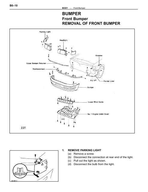
B0–10<br />
BODY<br />
–<br />
<strong>Front</strong> Bumper<br />
BUMPER<br />
<strong>Front</strong> Bumper<br />
REMOVAL OF FRONT BUMPER<br />
1. REMOVE PARKING LIGHT<br />
(a) Remove a screw.<br />
(b) Disconnect the connection at rear end of the light.<br />
(c) Pull out the light as shown.<br />
(d) Disconnect the bulb from the light.
BODY<br />
–<br />
<strong>Front</strong> Bumper<br />
B0–11<br />
2. REMOVE HEADLIGHT<br />
(a) Remove three bolts, a nut and the headlight.<br />
(b) Disconnect the connectors.<br />
3. REMOVE NO.1 ENGINE UNDER COVER<br />
Remove eight bolts, five screws and the cover.<br />
4. REMOVE LOWER WIND GUIDE<br />
(a) Disconnect the tube from the guide.<br />
(b) Remove seven screws and the guide.<br />
5. REMOVE FENDER LINER FROM BUMPER<br />
Remove six screws and the liner from <strong>bumper</strong>.<br />
6. REMOVE BUMPER AND UPPER BUMPER RETAINER<br />
(a) Remove two nuts and a retainer.<br />
(b) Remove two bolts from the <strong>bumper</strong>.
B0–12<br />
BODY<br />
–<br />
<strong>Front</strong> Bumper<br />
(c) Loosen the clips, then remove the clip with a clip<br />
remover and the upper <strong>bumper</strong> retainer.<br />
(d) Remove four bolts.<br />
(e) Disconnect the bulbs from the <strong>bumper</strong>.<br />
(f) Disconnect the connection at the <strong>bumper</strong> rear end, then<br />
pull the <strong>bumper</strong> forward to remove it.<br />
HINT: When pulling out the <strong>bumper</strong>, be careful not to<br />
damage the serrated part of side bolts.<br />
7. REMOVE REINFORCEMENT<br />
Remove ten bolts and the reinforcement.<br />
INSTALLATION OF FRONT BUMPER<br />
(See page BO–10)<br />
INSTALL FRONT BUMPER PARTS BY FOLLOWING REMOVAL<br />
SEQUENCE IN REVERSE<br />
HINT:<br />
• When installing the <strong>bumper</strong> on the body, be careful not<br />
to damage the serrated part of side bolts.<br />
• At installing the stay, place the retainer in hole, then<br />
push in the head of the clip and install it.<br />
• After installing the headlight, adjust the light aiming.<br />
(See page BE–35)
BODY – <strong>Front</strong> Bumper<br />
DISASSEMBLY OF FRONT BUMPER<br />
B0–13<br />
1. REMOVE FRONT BUMPER MOULDING<br />
(a) Using a screwdriver, pry out the side joining of the<br />
moulding.<br />
HINT: Tape the screwdriver tip before use.
B0–14<br />
BODY<br />
–<br />
<strong>Front</strong> Bumper<br />
(b) Using a knife, cut the adhesive tape while pulling the<br />
moulding.<br />
HINT: Do not scratch the cover with the knife.<br />
2. REMOVE SIDE MARKER LIGHT<br />
(a) Remove a screw.<br />
(b) Pull out the light and remove it.<br />
3. REMOVE TURN SIGNAL LIGHT<br />
(a) Remove a screw.<br />
(b) Slide the light as shown, and remove it.<br />
4. REMOVE BUMPER FILLER AND BRACKET<br />
Using a clip remover, remove the <strong>bumper</strong> filler and the<br />
bracket.<br />
5. REMOVE FRONT SPOILER AND UPPER SPOILER<br />
RETAINER<br />
Remove three nuts and remove the spoiler and the retainer.<br />
6. REMOVE NO.2 LOWER RETAINER AND GROMMETS<br />
Using pliers, remove seven grommets and the retainer.
BODY<br />
–<br />
<strong>Front</strong> Bumper<br />
B0–15<br />
7. REMOVE NO.1 AND NO.2 SIDE RETAINERS<br />
(a) Using about 3.2 mm (0.126 in.) drill, drill out the rivet<br />
heads.<br />
(b) Remove No.2 side retainer.<br />
(c) Remove No.1 side retainer in a same manner.<br />
8. REMOVE REINFORCEMENT AND ENERGY ABSORBER<br />
(a) Remove six clips from the lower retainer.<br />
(b) Remove reinforcement and energy absorber from<br />
<strong>bumper</strong> cover.<br />
9. REMOVE NO.1 LOWER RETAINER<br />
(a) Using about 3.2 mm (0.126 in.) drill, drill out the rivet<br />
heads.<br />
(b) Remove the retainer.<br />
ASSEMBLY OF FRONT BUMPER<br />
(See page BO–13)<br />
ASSEMBLE FRONT BUMPER PARTS BY FOLLOWING DIS-<br />
ASSEMBLY SEQUENCE IN REVERSE<br />
1. INSTALL UPPER RETAINER AND NO.2 SIDE RETAINERS<br />
(a) Place the retainers in the <strong>bumper</strong> cover.<br />
(b) Using a riveter, install the rivet.<br />
2. INSTALL FRONT BUMPER MOULDING<br />
HINT:<br />
• If double–sided tape of the moulding is not usable,<br />
replace it for new tape.<br />
• When re–using the moulding, replace the double–sided<br />
tape.<br />
Align the bosses of moulding with the holes of the <strong>bumper</strong><br />
cover, then push the moulding on the <strong>bumper</strong> to install it.

![16 RELAY LOCATIONS [Engine Compartment] [Body] - Lextreme.com](https://img.yumpu.com/46854657/1/190x245/16-relay-locations-engine-compartment-body-lextremecom.jpg?quality=85)