Technologies Behind NEC's High Temperature Ambient Server
Technologies Behind NEC's High Temperature Ambient Server
Technologies Behind NEC's High Temperature Ambient Server

Create successful ePaper yourself
Turn your PDF publications into a flip-book with our unique Google optimized e-Paper software.
<strong>Technologies</strong> <strong>Behind</strong> NEC’s <strong>High</strong> <strong>Temperature</strong> <strong>Ambient</strong> <strong>Server</strong><br />
Environment<br />
• NEC IT platform Testing Center with 200 to 300 servers, storage devices, and<br />
network devices installed.<br />
• Eight air conditioners under operation<br />
• Total power of approximately 150 kW<br />
Issues<br />
• It is difficult to separate cool and warm air because there is no underfloor<br />
cooling system.<br />
The environment used for verification is a space designed to assess ICT<br />
equipment before shipment and therefore does not have any underfloor cooling<br />
system. It was therefore difficult to control the cool and warm air.<br />
• Frequent unit displacement and fluctuation of operating rate<br />
Multiple ICT devices are tested at the same time in the testing center and the<br />
device configuration is frequently changed according to the type of test. It is<br />
therefore difficult to keep the temperature constant, leaving no choice but to set<br />
the cooling system to a low temperature to avoid the generation of hot spots.<br />
Investigation<br />
After performing measurement across the whole floor, it was found that there were<br />
many low temperature areas where the indoor temperature was 23°C or less.<br />
Analysis<br />
As a result of performing heat analysis using an analysis tool, it was determined that<br />
five air conditioners could cover the current amount of heat generation. Three of the<br />
eight operating air conditioners were therefore stopped and the optimal temperature<br />
(25°C to 30°C) was successfully achieved at the air inlets of the ICT equipment.* 3<br />
Measures<br />
We determined the positions of the three operating air conditioners that had to be<br />
stopped by using heat analysis.<br />
We also implemented measures to optimize the airflow of exhaust heat by using a<br />
capping method and adjusted the airflow direction of the cooling system for some<br />
racks to realize airflow control in which hot spots would not be generated even if<br />
those three air conditioners were stopped.<br />
Results<br />
We succeeded in reducing the cooling system power consumption from the<br />
current 24 kW to 15 kW (a reduction of 37%) without generating hot spots. This<br />
will lead to savings of approximately 1.1 million yen in annual power charges* 4 .<br />
As described above, it was demonstrated that the power consumption can be<br />
significantly reduced by raising the cooling system temperature. It is<br />
particularly difficult to maintain the supply of power to the cooling system when<br />
Development of NEC proprietary cooling technology using thermosiphon cooling<br />
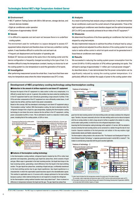
Reduction in the amount of airflow required to cool down ICT equipment<br />
Because the layout of the ICT equipment in a data center is often very complicated, it is<br />
difficult to evenly feed in cool air. In general, this problem has been solved by installing fans<br />
in the ICT equipment itself to cool it directly by generating a large amount of airflow. If the<br />
CPUs and other components of the ICT equipment are more efficiently cooled down, it will<br />
require less fan airflow, and thus result in less power consumption.<br />
Based on this concept, NEC has developed a technology to cool down ICT equipment using a<br />
“thermosiphon cooling” method. With thermosiphon cooling, the heat is absorbed when the<br />
refrigerant changes from a liquid to a gas (evaporates). Applying this thermosiphon cooling<br />
technology to cool down the server reduces the fan airflow in the ICT equipment, cutting<br />
power consumption by 60% or more. This is estimated to result in a reduction in total cooling<br />
power, including that of the cooling system, of 20% or more.<br />
The amount of airflow from the cooling system<br />
can be reduced by cooling down<br />
the ICT equipment with a small amount of airflow.<br />
Amount of airflow in<br />
the ICT equipment100<br />
Elimination of hot spots Measures to reduce<br />
the amount of airflow<br />
Amount of airflow in<br />
the ICT equipment70<br />
Reducing the large amount of<br />
airflow for this rack eliminates<br />
hot spots. (It is not necessary to<br />
reduce the amount of airflow for<br />
all the racks.)<br />
It was verified that the power for the fan for a 1U server was<br />
reduced by 60% or more by adopting the thermosiphon cooling<br />
Thermosiphon<br />
cooling<br />
Features of thermosiphon cooling technology<br />
In the thermosiphon cooling method, refrigerant liquid is heated by the CPU or other heat<br />
generator and evaporates, generating a gas-liquid two-phase flow, which consists of liquid<br />
and gas. When vapor is generated in the heat receiving section, the liquid level drops in the<br />
heat receiving section, generating a level difference from the liquid in the heat emitting<br />
section. The gas-liquid two-phase flow, consisting of liquid and gas, is efficiently transferred<br />
to the heat emitting section due to gas-liquid equilibrium. Gas-liquid equilibrium is a<br />
characteristic in which the vaporization speed becomes equal to the devolatilization speed.<br />
This method is applicable even to 1U servers with a design optimized for the best airflow<br />
because a pump or other external driving force is not required to circulate the refrigerant.<br />
As the thermosiphon cooling method transfers heat using latent heat* 5 , there is almost no<br />
difference in temperature between the liquid and the gas. The gas-liquid two-phase flow<br />
<br />
<br />
<br />
<br />
<br />
<br />
technology. T he total power<br />
required for cooling, including<br />
that of the cooling system, could<br />
be reduced by 20% or more.<br />
<strong>Server</strong> fan<br />
Power consumed by fan airflow<br />
Power consumed by refrigerator<br />
55<br />
54<br />
30 Reduction by<br />
60%<br />
15<br />
21<br />
5<br />
Current Cooling using less air<br />
Features of technology – 1<br />
Heat receiving section Heat emitting section Heat receiving section Heat emitting section<br />
Vapor<br />
Vapor + liquid Liquid<br />
Heat generator<br />
Liquid<br />
Radiation fin<br />
Because there is a fin flow channel, generated air bubbles<br />
include surrounding liquid and become a gas-liquid<br />
two-phase flow when rising due to buoyancy.<br />
When vapor starts to occur, the liquid in the heat receiving section<br />
drops, generating a level difference and refrigerant circulates to achieve<br />
a gas-liquid equilibrium. (The vaporization speed is equal to the<br />
condensation speed.)<br />
goes from the heat receiving section to the heat emitting section and simply condenses the refrigerant<br />
vapor. Therefore, the power consumed by the fan in the heat emitting section can be reduced compared<br />
with the air-cooling method, in which a large amount of airflow is supplied to the radiator for cooling,<br />
and the water-cooling method, in which the rise in the refrigerant temperature is large.<br />
Assuming that this thermosiphon cooling technology will be applied to 1U servers, NEC has adopted a<br />
structure whereby the heat receiving section can be connected to a radiator through the tube for heat<br />
transfer. Separate installation of the heat generator and radiator in this way enables a high<br />
implementation density and flexible component layout.<br />
The thermosiphon cooling module is the outcome of the “The Research and Development Project for<br />
Green Network/System Technology,” a Japanese government project in which NEC is involved* 6 . This<br />
module is currently being researched with the goal of practical application.<br />
Features of technology - 2<br />
An air duct structure is used to cool down all<br />
the ICT equipment by using airflow<br />
management technology.<br />
Heat emitting section<br />
(flow line graph)<br />
<br />
Condensation<br />
part<br />
Condensation part equipped with<br />
a guide vane that concentrates<br />
airflow onto the memory.<br />
Vapor<br />
<br />
Chipset<br />
<br />
<br />
<br />
<br />
Heat receiving section<br />
(flow line graph)<br />
Chipset<br />
Heat receiving<br />
section<br />
Cylinder-type vaporization part,<br />
which sends airflow to the chipset<br />
Operating<br />
temperature<br />
<strong>Temperature</strong> rise<br />
<br />
CPU<br />
Rated<br />
temperature<br />
<br />
<br />
<br />
<br />
<br />
Fan powerW<br />
<strong>Temperature</strong> rise<br />
Thermosiphon<br />
<br />
Air cooling (21W)<br />
6<br />
Without air duct<br />
<br />
Parts other than<br />
CPU<br />
<br />
<br />
<br />
<br />
Liquid level<br />
Reduction of 60% or more<br />
Thermosiphon<br />
6<br />
With air duct<br />
Air cooling (21W)<br />
<br />
*5 Latent heat indicates that the temperature remains the same even if the state changes.<br />
For example, water evaporates and becomes vapor at 100°C and ice melts and becomes water at 0°C.<br />
*6 This project is being run by the New Energy and Industrial Technology Development Organization (NEDO),<br />
an Incorporated Administrative Agency of Japan.<br />
OFF<br />
ON<br />
© 2012 NEC Corporation The NEC logo is a registered trademark or a trademark of NEC Corporation in Japan and other countries.<br />
6