Alpha 22M Siren - Busch & Associates
Alpha 22M Siren - Busch & Associates
Alpha 22M Siren - Busch & Associates

Create successful ePaper yourself
Turn your PDF publications into a flip-book with our unique Google optimized e-Paper software.
®<br />
ENGINEERING COMPANY INC.<br />
51 Winthrop Road<br />
Chester, Connecticut 06412-0684<br />
Phone: (860) 526-9504<br />
Fax: (860) 526-4078<br />
Internet: www.whelen.com<br />
Sales e-mail: autosale@whelen.com<br />
Canadian Sales e-mail: autocan@whelen.com<br />
Customer Service e-mail: custserv@whelen.com<br />
Installation Guide:<br />
Model ALPHA<strong>22M</strong><br />
Remote <strong>Siren</strong> Amplifier<br />
Automotive: <strong>Siren</strong>s/Switches<br />
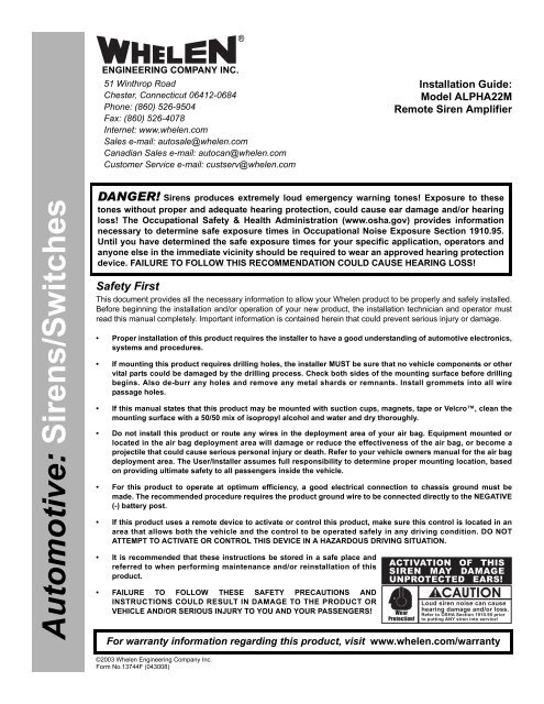
DANGER! <strong>Siren</strong>s produces extremely loud emergency warning tones! Exposure to these<br />
tones without proper and adequate hearing protection, could cause ear damage and/or hearing<br />
loss! The Occupational Safety & Health Administration (www.osha.gov) provides information<br />
necessary to determine safe exposure times in Occupational Noise Exposure Section 1910.95.<br />
Until you have determined the safe exposure times for your specific application, operators and<br />
anyone else in the immediate vicinity should be required to wear an approved hearing protection<br />
device. FAILURE TO FOLLOW THIS RECOMMENDATION COULD CAUSE HEARING LOSS!<br />
Safety First<br />
This document provides all the necessary information to allow your Whelen product to be properly and safely installed.<br />
Before beginning the installation and/or operation of your new product, the installation technician and operator must<br />
read this manual completely. Important information is contained herein that could prevent serious injury or damage.<br />
• Proper installation of this product requires the installer to have a good understanding of automotive electronics,<br />
systems and procedures.<br />
• If mounting this product requires drilling holes, the installer MUST be sure that no vehicle components or other<br />
vital parts could be damaged by the drilling process. Check both sides of the mounting surface before drilling<br />
begins. Also de-burr any holes and remove any metal shards or remnants. Install grommets into all wire<br />
passage holes.<br />
• If this manual states that this product may be mounted with suction cups, magnets, tape or Velcro, clean the<br />
mounting surface with a 50/50 mix of isopropyl alcohol and water and dry thoroughly.<br />
• Do not install this product or route any wires in the deployment area of your air bag. Equipment mounted or<br />
located in the air bag deployment area will damage or reduce the effectiveness of the air bag, or become a<br />
projectile that could cause serious personal injury or death. Refer to your vehicle owners manual for the air bag<br />
deployment area. The User/Installer assumes full responsibility to determine proper mounting location, based<br />
on providing ultimate safety to all passengers inside the vehicle.<br />
• For this product to operate at optimum efficiency, a good electrical connection to chassis ground must be<br />
made. The recommended procedure requires the product ground wire to be connected directly to the NEGATIVE<br />
(-) battery post.<br />
• If this product uses a remote device to activate or control this product, make sure this control is located in an<br />
area that allows both the vehicle and the control to be operated safely in any driving condition. DO NOT<br />
ATTEMPT TO ACTIVATE OR CONTROL THIS DEVICE IN A HAZARDOUS DRIVING SITUATION.<br />
• It is recommended that these instructions be stored in a safe place and<br />
referred to when performing maintenance and/or reinstallation of this<br />
product.<br />
• FAILURE TO FOLLOW THESE SAFETY PRECAUTIONS AND<br />
INSTRUCTIONS COULD RESULT IN DAMAGE TO THE PRODUCT OR<br />
VEHICLE AND/OR SERIOUS INJURY TO YOU AND YOUR PASSENGERS!<br />
ACTIVATION OF THIS<br />
SIREN MAY DAMAGE<br />
UNPROTECTED EARS!<br />
Wear<br />
Protection!<br />
CAUTION<br />
Loud siren noise can cause<br />
hearing damage and/or loss.<br />
Refer to OSHA Section 1910.95 prior<br />
to putting ANY siren into service!<br />
For warranty information regarding this product, visit www.whelen.com/warranty<br />
©2003 Whelen Engineering Company Inc.<br />
Form No.13744F (043008)<br />
Page 1
WARNING! If the ALPHA<strong>22M</strong> is replacing the siren<br />
amplifier in an existing siren system, that systems<br />
switches MUST be rewired to match the corresponding<br />
<strong>Alpha</strong> switch wiring diagram found in this manual. If<br />
the existing system does not use <strong>Alpha</strong> switches, refer<br />
to the wiring information on page 7 to rewire your<br />
switches.<br />
Mounting the ALPHA<strong>22M</strong><br />
1. Locate a suitable mounting location for the ALPHA<strong>22M</strong>. The<br />
vertical wall between the trunk and the passenger<br />
compartment is often a good choice and is the method<br />
discussed in this manual.<br />
2. Be sure that the remote amplifier fits properly and does not<br />
interfere with any parts of the trunk lid or seat back.<br />
3. Position the remote amplifier on the proposed mounting<br />
location. Using an awl or other suitable tool, scribe the<br />
mounting surface where the mounting holes are to be drilled.<br />
CAUTION! As mounting the ALPHA<strong>22M</strong> will require drilling, it<br />
is absolutely necessary to make sure that no other vehicle<br />
components could be damaged by the drilling process. If any<br />
vehicle component could suffer any potential harm, select a<br />
different mounting location.<br />
4. Carefully drill the mounting holes using a drill bit sized for a<br />
#10 sheet metal screw.<br />
5. Using the supplied #10 x 3/4” sheet metal screws, secure the<br />
remote amplifier to the vertical trunk wall.<br />
Wiring the ALPHA<strong>22M</strong> 16 position connector<br />
Connecting to Power:<br />
1. Extend the RED and BLACK wires through the firewall and<br />
into the engine compartment.<br />
2. Follow the factory wiring harness towards your vehicle’s<br />
battery.<br />
3. Connect the RED wire to one end of a user supplied fuse<br />
block. Do not connect this unit to the battery yet!<br />
4. Connect the BLACK wire directly to the NEGATIVE battery<br />
terminal.<br />
Connecting to your Speaker(s):<br />
1. Route the ORANGE, YELLOW and BROWN wires along the<br />
factory wiring harness towards your speaker(s).<br />
2. Connect the ORANGE wire to the POSITIVE (+) terminal on<br />
speaker #1. If two speakers (100 watt max. each) are used,<br />
connect the YELLOW wire to the POSITIVE (+) terminal on<br />
speaker #2.<br />
If only one speaker is being used, the YELLOW wire must be<br />
cut flush with its insulation and capped to prevent this wire<br />
from shorting to ground.<br />
3. Connect the BROWN wire to the NEGATIVE (-) terminal on<br />
speaker #1. If two speakers are used, splice and connect the<br />
BROWN wire to the NEGATIVE (-) terminals on speakers #1<br />
and #2.<br />
Wiring the ALPHA<strong>22M</strong><br />
The ALPHA<strong>22M</strong> can operate in two modes:<br />
• Mechanical <strong>Siren</strong>-mode (default)<br />
• Power Call-mode<br />
The operating mode is determined by the position of Dip Switch #6.<br />
In the default position (mechanical siren-mode) this switch is ON.<br />
Moving this switch to the OFF position places the ALPHA<strong>22M</strong> in<br />
Power Call-mode. The remaining 5 dip switches perform different<br />
functions in each mode. Additionaly, the wiring of the ALPHA<strong>22M</strong><br />
is different for each mode. Refer to the appropriate section for detailed<br />
wiring information.<br />
WARNING! All customer supplied wires that connect to the<br />
positive terminal of the battery must be sized to supply at<br />
least 125% of the maximum operating current and FUSED at<br />
the battery to carry that load. DO NOT USE CIRCUIT<br />
BREAKERS WITH THIS PRODUCT!<br />
Dip Switch Functions:<br />
Dip<br />
Switch<br />
3<br />
Dip<br />
Switch<br />
4<br />
Mechanical <strong>Siren</strong> Mode<br />
Horn Ring Function<br />
ON<br />
ON<br />
OFF<br />
OFF<br />
ON<br />
OFF<br />
ON<br />
OFF<br />
Initiate Air Horn with horn ring<br />
Simulate mechanical siren “brake” with horn ring<br />
Initiate Manual tone with horn ring<br />
INVALID SELECTION - Do Not Use<br />
NOTE -<br />
Dip Switch 5 has no function in mechanical siren Mode<br />
Dip<br />
Switch<br />
3<br />
ON<br />
OFF<br />
Dip<br />
Switch<br />
4<br />
ON<br />
OFF<br />
Dip<br />
Switch<br />
5<br />
ON<br />
OFF<br />
Power Call Mode<br />
Worble Override Options<br />
Worble has push-on/push-off override<br />
Worble has no override<br />
Wail/Worble Override Options<br />
Wail has push-on/push-off Worble override<br />
Worble has 10-second Worble override<br />
Wail Tone Options<br />
Simulated mechanical tone for Wail<br />
Normal Wail Tone<br />
Page 2
Mechanical <strong>Siren</strong> Mode -<br />
Wiring Diagram using the <strong>Alpha</strong> 1 switch assembly<br />
ALPHA<strong>22M</strong><br />
REMOTE<br />
AMPLIFIER<br />
All DIP<br />
SWITCHES<br />
ON<br />
(DEFAULT)<br />
PIN 3<br />
PIN 7<br />
WHT/BRN<br />
PIN 8 WHT/RED<br />
PIN 9 WHT/ORN<br />
PIN 10 WHT/YEL<br />
PIN 11 WHT/GRN<br />
PIN 12 GRN<br />
PIN 13 N/C<br />
PIN 14 RED/WHT<br />
PIN 5<br />
PIN 4<br />
WHT/BLK<br />
ORN<br />
BRN<br />
(aux. ground)<br />
(control 1)<br />
(control 2)<br />
(control 3)<br />
(control 4)<br />
(speaker #1)<br />
(speaker ground)<br />
BUTT SPLICES<br />
Speaker 1<br />
100 Watt<br />
GRN<br />
RED<br />
GRY<br />
WHT<br />
SW1<br />
WHT/GRN<br />
WHT<br />
PIN 6 YEL (speaker #2)<br />
PIN 1<br />
PIN 2<br />
BLK<br />
BLK<br />
PIN 15 RED<br />
PIN 16 RED<br />
(ground)<br />
(ground)<br />
(+12VDC)<br />
(+12VDC)<br />
20 AMP<br />
FUSE<br />
Speaker 2<br />
100 Watt<br />
HORN<br />
RELAY<br />
CUT<br />
WIRE<br />
VEHICLE<br />
HORN<br />
BATTERY<br />
When switch is in<br />
this position....<br />
this siren tone<br />
is generated....<br />
and the Horn Ring<br />
activates....<br />
SW1 ON<br />
SW1 OFF<br />
Mechanical Wail<br />
NO TONE<br />
Air Horn<br />
Vehicle Horn<br />
Wiring Diagram using the <strong>Alpha</strong> 2 switch assembly<br />
ALPHA<strong>22M</strong><br />
REMOTE<br />
AMPLIFIER<br />
All DIP<br />
SWITCHES<br />
ON<br />
(DEFAULT)<br />
PIN 3<br />
PIN 7<br />
WHT/BRN<br />
PIN 8 WHT/RED<br />
PIN 9 WHT/ORN<br />
PIN 10 WHT/YEL<br />
PIN 11 WHT/GRN<br />
PIN 12 GRN<br />
PIN 13 N/C<br />
PIN 14 RED/WHT<br />
PIN 5<br />
PIN 4<br />
WHT/BLK<br />
ORN<br />
BRN<br />
(aux. ground)<br />
(control 1)<br />
(control 2)<br />
(control 3)<br />
(control 4)<br />
(speaker #1)<br />
(speaker ground)<br />
BUTT SPLICES<br />
Speaker 1<br />
100 Watt<br />
GRN<br />
RED<br />
SW2<br />
GRY<br />
WHT<br />
SW1<br />
WHT/GRN<br />
WHT<br />
PIN 6 YEL (speaker #2)<br />
PIN 1<br />
PIN 2<br />
BLK<br />
BLK<br />
PIN 15 RED<br />
PIN 16 RED<br />
(ground)<br />
(ground)<br />
(+12VDC)<br />
(+12VDC)<br />
20 AMP<br />
FUSE<br />
Speaker 2<br />
100 Watt<br />
HORN<br />
RELAY<br />
CUT<br />
WIRE<br />
VEHICLE<br />
HORN<br />
BATTERY<br />
When switches are<br />
in this position....<br />
this siren tone<br />
is generated....<br />
and pressing SW2<br />
will activate....<br />
and the Horn Ring<br />
activates....<br />
SW1 ON<br />
Mechanical Wail<br />
Air Horn<br />
Air Horn<br />
SW1 OFF<br />
NO TONE<br />
Air Horn<br />
Vehicle Horn<br />
Page 3
Wiring Diagram using the <strong>Alpha</strong> 3 switch assembly<br />
ALPHA<strong>22M</strong><br />
REMOTE<br />
AMPLIFIER<br />
All DIP<br />
SWITCHES<br />
ON<br />
(DEFAULT)<br />
PIN 3<br />
PIN 7<br />
WHT/BRN<br />
PIN 8 WHT/RED<br />
PIN 9 WHT/ORN<br />
PIN 10 WHT/YEL<br />
PIN 11 WHT/GRN<br />
PIN 12 GRN<br />
PIN 13 N/C<br />
PIN 14 RED/WHT<br />
PIN 5<br />
PIN 4<br />
WHT/BLK<br />
ORN<br />
BRN<br />
(aux. ground)<br />
(control 1)<br />
(control 2)<br />
(control 3)<br />
(control 4)<br />
(speaker #1)<br />
(speaker ground)<br />
BUTT SPLICES<br />
1<br />
Speaker 1<br />
100 Watt<br />
SW2<br />
GRN<br />
RED<br />
SW1<br />
PIN 6 YEL (speaker #2)<br />
Speaker 2<br />
100 Watt<br />
DIODE<br />
A 1N4001 diode (customer supplied) must<br />
be added to the circuit as shown in the<br />
circuit to use the horn ring<br />
PIN 1<br />
PIN 2<br />
PIN 15<br />
PIN 16<br />
BLK<br />
BLK<br />
RED<br />
RED<br />
(ground)<br />
(ground)<br />
(+12VDC)<br />
(+12VDC)<br />
20 AMP<br />
FUSE<br />
HORN<br />
RELAY<br />
SPLICE<br />
VEHICLE<br />
HORN<br />
BATTERY<br />
When switches are<br />
in this position....<br />
this siren tone<br />
is generated....<br />
and pressing SW2<br />
will activate....<br />
and the Horn Ring<br />
activates....<br />
and the customer<br />
supplied Momentary<br />
switch activates....<br />
SW1 TONE 1<br />
Mechanical Wail<br />
Air Horn<br />
Air Horn +<br />
Vehicle Horn<br />
Manual override of<br />
Mechanical Wail<br />
SW1 OFF<br />
NO TONE<br />
Air Horn<br />
Air Horn +<br />
Vehicle Horn<br />
Manual tone activation<br />
(with ramp down on<br />
release)<br />
SW1 TONE 2<br />
Manual mode*<br />
Air Horn<br />
Air Horn +<br />
Vehicle Horn<br />
Manual tone activation<br />
(with ramp down on<br />
release)<br />
*when the siren is in “Manual mode”, no tone is generated until the customer supplied<br />
momentary switch is pressed. While this switch is pressed, the siren will produce a<br />
tone that will ramp up to a high pitched tone. This tone will be maintained at this pitch<br />
until the switch is released. The tone will then ramp down and stop.<br />
Wiring Diagram using the <strong>Alpha</strong> 4 switch assembly<br />
ALPHA<strong>22M</strong><br />
REMOTE<br />
AMPLIFIER<br />
All DIP<br />
SWITCHES<br />
ON<br />
(DEFAULT)<br />
PIN 3<br />
PIN 7<br />
WHT/BRN<br />
PIN 8 WHT/RED<br />
PIN 9 WHT/ORN<br />
PIN 10 WHT/YEL<br />
PIN 11 WHT/GRN<br />
PIN 12 GRN<br />
PIN 13 N/C<br />
PIN 14 RED/WHT<br />
PIN 5<br />
PIN 4<br />
WHT/BLK<br />
ORN<br />
BRN<br />
(aux. ground)<br />
(control 1)<br />
(control 2)<br />
(control 3)<br />
(control 4)<br />
(speaker #1)<br />
(speaker ground)<br />
BUTT SPLICES<br />
1<br />
Speaker 1<br />
100 Watt<br />
SW3<br />
SW2<br />
GRY<br />
WHT<br />
SW1<br />
PIN 6 YEL (speaker #2)<br />
PIN 1<br />
PIN 2<br />
BLK<br />
BLK<br />
PIN 15 RED<br />
PIN 16 RED<br />
(ground)<br />
(ground)<br />
(+12VDC)<br />
(+12VDC)<br />
20 AMP<br />
FUSE<br />
Speaker 2<br />
100 Watt<br />
HORN<br />
RELAY<br />
CUT<br />
WIRE<br />
VEHICLE<br />
HORN<br />
BATTERY<br />
When switches are<br />
in this position....<br />
this siren tone<br />
is generated....<br />
and pressing SW3<br />
will activate....<br />
and the Horn Ring<br />
activates....<br />
and the customer supplied<br />
momentary switch activates....<br />
SW2 TONE 1<br />
SW2 OFF<br />
SW2 TONE 2<br />
SW1 ON<br />
SW1 OFF<br />
Mechanical Wail<br />
NO TONE<br />
Air Horn<br />
NO TONE<br />
Air Horn<br />
Vehicle Horn<br />
SW1 ON Manual mode* Air Horn<br />
Air Horn<br />
SW1 OFF NO TONE<br />
NO TONE<br />
Vehicle Horn<br />
SW1 ON Manual mode* Air Horn<br />
Air Horn<br />
SW1 OFF NO TONE<br />
NO TONE<br />
Vehicle Horn<br />
Manual override of Mechanical Wail<br />
Manual tone activation (ramp down on release)<br />
Manual tone activation (ramp down on release)<br />
Manual tone activation (ramp down on release)<br />
Manual tone activation (ramp down on release)<br />
Manual tone activation (ramp down on release)<br />
*when the siren is in “Manual mode”, no tone is generated until the customer supplied<br />
momentary switch is pressed. While this switch is pressed, the siren will produce a<br />
tone that will ramp up to a high pitched tone. This tone will be maintained at this pitch<br />
until the switch is released. The tone will then ramp down and stop.<br />
Page 4
Power Call Mode -<br />
Wiring Diagram using the <strong>Alpha</strong> 1 switch assembly<br />
ALPHA<strong>22M</strong><br />
REMOTE<br />
AMPLIFIER<br />
DIP<br />
SWITCHES<br />
1-4<br />
ON<br />
5,6<br />
OFF<br />
PIN 3<br />
PIN 7<br />
PIN 8<br />
PIN 9<br />
PIN 10<br />
PIN 11<br />
PIN 12<br />
PIN 13<br />
PIN 14<br />
WHT/BRN<br />
WHT/RED<br />
WHT/ORN<br />
WHT/YEL<br />
WHT/GRN<br />
GRN<br />
N/C<br />
RED/WHT<br />
(control 1)<br />
(control 2)<br />
(control 3)<br />
(control 4)<br />
PIN 5<br />
PIN 4<br />
WHT/BLK<br />
ORN<br />
BRN<br />
(aux. ground)<br />
(speaker #1)<br />
(speaker ground)<br />
PIN 6 YEL (speaker #2)<br />
SEE OPTION TABLE<br />
BUTT SPLICES<br />
Speaker 1<br />
100 Watt<br />
Speaker 2<br />
100 Watt<br />
HORN<br />
RELAY<br />
GRN<br />
RED<br />
GRY<br />
WHT<br />
SW1<br />
WHT/GRN<br />
WHT<br />
PIN 1<br />
PIN 2<br />
PIN 15<br />
PIN 16<br />
BLK<br />
BLK<br />
RED<br />
RED<br />
(ground)<br />
(ground)<br />
(+12VDC)<br />
(+12VDC)<br />
20 AMP<br />
FUSE<br />
CUT<br />
WIRE<br />
VEHICLE<br />
HORN<br />
BATTERY<br />
When switch is in<br />
this position....<br />
SW1 ON<br />
connecting the GREEN<br />
to this wire will generate<br />
this siren tone....<br />
WHT/BRN = Whoop<br />
WHT/RED = Warble<br />
WHT/ORN = Wail<br />
and the Horn Ring<br />
activated override<br />
tone is....<br />
Air Horn<br />
Whoop<br />
Warble<br />
SW1 OFF<br />
NO TONE<br />
Vehicle Horn<br />
Wiring Diagram using the <strong>Alpha</strong> 2 switch assembly<br />
ALPHA<strong>22M</strong><br />
REMOTE<br />
AMPLIFIER<br />
DIP<br />
SWITCHES<br />
1-4<br />
ON<br />
5,6<br />
OFF<br />
PIN 3<br />
PIN 7<br />
PIN 8<br />
PIN 9<br />
PIN 10<br />
PIN 11<br />
PIN 12<br />
PIN 13<br />
PIN 14<br />
WHT/BRN<br />
WHT/RED<br />
WHT/ORN<br />
WHT/YEL<br />
WHT/GRN<br />
GRN<br />
N/C<br />
RED/WHT<br />
(control 1)<br />
(control 2)<br />
(control 3)<br />
(control 4)<br />
PIN 5<br />
PIN 4<br />
WHT/BLK<br />
ORN<br />
BRN<br />
(aux. ground)<br />
(speaker #1)<br />
(speaker ground)<br />
PIN 6 YEL (speaker #2)<br />
SEE OPTION TABLE<br />
BUTT SPLICES<br />
Speaker 1<br />
100 Watt<br />
Speaker 2<br />
100 Watt<br />
HORN<br />
RELAY<br />
SW2<br />
GRN<br />
RED<br />
GRY<br />
WHT<br />
SW1<br />
WHT/GRN<br />
WHT<br />
PIN 1<br />
PIN 2<br />
PIN 15<br />
PIN 16<br />
BLK<br />
BLK<br />
RED<br />
RED<br />
(ground)<br />
(ground)<br />
(+12VDC)<br />
(+12VDC)<br />
20 AMP<br />
FUSE<br />
CUT<br />
WIRE<br />
VEHICLE<br />
HORN<br />
BATTERY<br />
When switch is in<br />
this position....<br />
connecting the GREEN<br />
to this wire will generate<br />
this siren tone....<br />
and pressing SW2<br />
will activate....<br />
and the Horn Ring<br />
activated override<br />
tone is....<br />
SW1 ON<br />
WHT/BRN = Whoop<br />
WHT/RED = Warble<br />
WHT/ORN = Wail<br />
Air Horn<br />
Air Horn<br />
Whoop<br />
Warble<br />
SW1 OFF<br />
NO TONE<br />
Air Horn<br />
Vehicle Horn<br />
Page 5
Wiring Diagram using the <strong>Alpha</strong> 3 switch assembly<br />
ALPHA<strong>22M</strong><br />
REMOTE<br />
AMPLIFIER<br />
DIP<br />
SWITCHES<br />
1-4<br />
ON<br />
5,6<br />
OFF<br />
PIN 3<br />
PIN 7<br />
PIN 8<br />
PIN 9<br />
PIN 10<br />
PIN 11<br />
PIN 12<br />
PIN 13<br />
PIN 14<br />
WHT/BRN<br />
WHT/RED<br />
WHT/ORN<br />
WHT/YEL<br />
WHT/GRN<br />
GRN<br />
N/C<br />
RED/WHT<br />
(control 1)<br />
(control 2)<br />
(control 3)<br />
(control 4)<br />
PIN 5<br />
PIN 4<br />
WHT/BLK<br />
ORN<br />
BRN<br />
(aux. ground)<br />
(speaker #1)<br />
(speaker ground)<br />
PIN 6 YEL (speaker #2)<br />
SEE OPTION TABLE<br />
BUTT SPLICES<br />
Speaker 1<br />
100 Watt<br />
Speaker 2<br />
100 Watt<br />
DIODE<br />
SW2<br />
GRN<br />
RED<br />
VIO<br />
SW1<br />
A 1N4001 diode (customer supplied) must<br />
be added to the circuit as shown in the<br />
circuit to use the horn ring<br />
PIN 1<br />
PIN 2<br />
PIN 15<br />
PIN 16<br />
BLK<br />
BLK<br />
RED<br />
RED<br />
(ground)<br />
(ground)<br />
(+12VDC)<br />
(+12VDC)<br />
20 AMP<br />
FUSE<br />
HORN<br />
RELAY<br />
SPLICE<br />
VEHICLE<br />
HORN<br />
BATTERY<br />
When switch is in<br />
this position....<br />
connecting the GREEN<br />
wire to this wire will<br />
determine Tone 1....<br />
and pressing SW2<br />
will activate....<br />
and the Horn Ring<br />
activated override<br />
tone is....<br />
SW1 Tone 1<br />
WHT/BRN = Whoop<br />
WHT/RED = Warble<br />
WHT/ORN = Wail<br />
Air Horn<br />
Air Horn<br />
Air Horn<br />
Air Horn + Vehicle Horn<br />
Whoop + Vehicle Horn<br />
Warble + Vehicle Horn<br />
SW1 OFF<br />
NO TONE<br />
Air Horn<br />
Vehicle Horn<br />
When switch is in<br />
this position....<br />
connecting the VIOLET<br />
wire to this wire will<br />
determine Tone 2....<br />
and pressing SW2<br />
will activate....<br />
and the Horn Ring<br />
activated override<br />
tone is....<br />
SW1 Tone 2<br />
WHT/BRN = Whoop<br />
WHT/RED = Warble<br />
WHT/ORN = Wail<br />
Air Horn<br />
Air Horn<br />
Air Horn<br />
Air Horn + Vehicle Horn<br />
Whoop + Vehicle Horn<br />
Warble + Vehicle Horn<br />
Wiring Diagram using the <strong>Alpha</strong> 4 switch assembly<br />
ALPHA<strong>22M</strong><br />
REMOTE<br />
AMPLIFIER<br />
DIP<br />
SWITCHES<br />
1-4<br />
ON<br />
5,6<br />
OFF<br />
PIN 3<br />
PIN 7<br />
PIN 8<br />
PIN 9<br />
PIN 10<br />
PIN 11<br />
PIN 12<br />
PIN 13<br />
PIN 14<br />
WHT/BRN<br />
WHT/RED<br />
WHT/ORN<br />
WHT/YEL<br />
WHT/GRN<br />
GRN<br />
N/C<br />
RED/WHT<br />
(control 1)<br />
(control 2)<br />
(control 3)<br />
(control 4)<br />
PIN 5<br />
PIN 4<br />
PIN 1<br />
PIN 2<br />
WHT/BLK<br />
ORN<br />
BRN<br />
BLK<br />
BLK<br />
PIN 15 RED<br />
PIN 16 RED<br />
(aux. ground)<br />
(speaker #1)<br />
(speaker ground)<br />
PIN 6 YEL (speaker #2)<br />
(ground)<br />
(ground)<br />
(+12VDC)<br />
(+12VDC)<br />
SEE OPTION TABLE<br />
BUTT SPLICES<br />
20 AMP<br />
FUSE<br />
GRN<br />
VIO<br />
Speaker 1<br />
100 Watt<br />
Speaker 2<br />
100 Watt<br />
BLK<br />
VIO<br />
SW3<br />
GRN<br />
HORN<br />
RELAY<br />
SW2<br />
CUT<br />
WIRE<br />
RED<br />
GRY<br />
WHT<br />
SW1<br />
VEHICLE<br />
HORN<br />
BATTERY<br />
When switches are<br />
in this position....<br />
connecting the GREEN<br />
wire to this wire will<br />
determine Tone 1....<br />
and pressing SW3<br />
will activate....<br />
and the Horn Ring<br />
activates....<br />
SW2 TONE 1<br />
SW1 ON<br />
WHT/BRN = Whoop<br />
WHT/RED = Warble<br />
WHT/ORN = Wail<br />
Air Horn<br />
Air Horn<br />
Air Horn<br />
Air Horn + Vehicle Horn<br />
Whoop + Vehicle Horn<br />
Warble + Vehicle Horn<br />
SW1 OFF<br />
NO TONE<br />
NO TONE<br />
Vehicle Horn<br />
SW2 OFF<br />
SW1 ON NO TONE<br />
SW1 OFF NO TONE<br />
connecting the VIOLET<br />
When switches are wire to this wire will<br />
in this position.... determine Tone 2....<br />
Air Horn<br />
NO TONE<br />
and pressing SW3<br />
will activate....<br />
Air Horn<br />
Vehicle Horn<br />
and the Horn Ring<br />
activates....<br />
SW2 TONE 2<br />
SW1 ON<br />
WHT/BRN = Whoop<br />
WHT/RED = Warble<br />
WHT/ORN = Wail<br />
Air Horn<br />
Air Horn<br />
Air Horn<br />
Air Horn + Vehicle Horn<br />
Whoop + Vehicle Horn<br />
Warble + Vehicle Horn<br />
SW1 OFF<br />
NO TONE<br />
NO TONE<br />
Vehicle Horn<br />
Page 6
The following diagrams provides basic switching information for installations that will not use <strong>Alpha</strong> switches.<br />
Mechanical <strong>Siren</strong> Mode -<br />
WHT/BRN (Mechanical <strong>Siren</strong> Wail)<br />
To Aux. Power (RED)<br />
WHT/GRN (Air Horn)*<br />
Connection shown for<br />
reference purposes only!<br />
WHT/RED (Mechanical <strong>Siren</strong> Manual)<br />
To Aux. Power (RED)<br />
WHT/GRN (to Amp)<br />
WHT/YEL (Air Horn)<br />
To Aux. Power (RED)<br />
To Switch Wiper<br />
Switch<br />
(SPDT)<br />
Power Call Mode -<br />
Horn<br />
Relay<br />
CUT<br />
WIRE<br />
Vehicle<br />
Horn<br />
WHT/BRN (Whoop)<br />
To Aux. Power (RED)<br />
WHT/GRN (Override)*<br />
WHT/RED (Warble)<br />
WHT/ORG (Wail)<br />
To Aux. Power (RED)<br />
WHT/YEL (Air Horn)<br />
To Aux. Power (RED)<br />
Connecting to your Horn Relay:<br />
1. Locate your vehicle’s horn relay. Now locate the wire that connects<br />
the vehicle horn to the horn relay and cut this wire.<br />
2. Extend each end of the cut wire (using a minimum 16 gauge wire) to<br />
a user supplied SPDT horn transfer switch.<br />
3. Connect the wire coming from the horn relay to the switch “wiper”<br />
(see reference diagram above).<br />
4. Connect the wire coming from the horn to one side of the switch<br />
(see reference diagram above).<br />
5. Connect the WHITE/GREEN* wire from the 16 position connector to<br />
the other side of the switch as shown.<br />
* The wiring diagrams assume the vehicle uses a positive<br />
activated horn ring signal. If this signal is ground<br />
activated, use the solid GREEN wire instead of the WHITE/<br />
GREEN wire<br />
The installation of your ALPHA<strong>22M</strong> series siren amplifier will be<br />
complete after the fuse block wire is connected to the POSITIVE (+)<br />
terminal of the battery. After this connection has been made, visually<br />
inspect the fuse on top of the amplifier and at the battery. If either of<br />
these fuses is blown, carefully inspect all of the circuit wires and make<br />
sure they are wired correctly. Replace the blown fuses with ones of an<br />
identical amp rating as the original. If these fuses blow after installation<br />
or activation, contact Whelen Engineering Technical Support.<br />
Input Voltage<br />
Input Current (Off)<br />
Input Current (Stand-By)<br />
Input Current (<strong>Siren</strong>)<br />
Output Voltage<br />
Speaker<br />
Output Power@15VDC<br />
Control Voltage<br />
Control Current<br />
H/R Voltage<br />
H/R Current<br />
Operating Temp.<br />
Operating Humidity<br />
Specifications<br />
-<br />
-<br />
-<br />
-<br />
-<br />
-<br />
-<br />
-<br />
-<br />
-<br />
-<br />
-<br />
-<br />
-<br />
13.5 VDC ±20%<br />
0mA<br />
90mA<br />
16 AMPS (w/200W <strong>Siren</strong>)<br />
18 AMPS (w/100W <strong>Siren</strong>)<br />
34 V RMS (MAX.)<br />
11 ohm (2 100 Watt MAX.)<br />
200 WATTS (MAX.)<br />
Input Voltage<br />
125mA (TYP.)<br />
Input Voltage or Ground<br />
15mA (TYP.)<br />
-30° C. to +60° C.<br />
95% Non Condensing<br />
ACTIVATION OF THIS<br />
SIREN MAY DAMAGE<br />
UNPROTECTED EARS!<br />
Wear<br />
Protection!<br />
CAUTION<br />
Loud siren noise can cause<br />
hearing damage and/or loss.<br />
Refer to OSHA Section 1910.95 prior<br />
to putting ANY siren into service!<br />
Page 7
Current Draw (AMPS)<br />
5<br />
10<br />
15<br />
20<br />
25<br />
30<br />
35<br />
40<br />
45<br />
50<br />
55<br />
60<br />
65<br />
70<br />
75<br />
80<br />
85<br />
90<br />
95<br />
100<br />
Wire Gauge<br />
Calculation Chart<br />
Wire Gage (AWG)<br />
22 20<br />
6 9.5<br />
3 5<br />
INS. 3<br />
INS. INS.<br />
INS.<br />
INS.<br />
INS.<br />
INS.<br />
INS.<br />
INS.<br />
INS.<br />
INS.<br />
INS.<br />
INS.<br />
INS.<br />
INS.<br />
INS.<br />
INS.<br />
INS.<br />
INS.<br />
INS. 3<br />
INS. INS.<br />
INS.<br />
INS.<br />
INS.<br />
INS.<br />
INS.<br />
INS.<br />
INS.<br />
INS.<br />
INS.<br />
INS.<br />
INS.<br />
INS.<br />
INS.<br />
INS.<br />
INS.<br />
INS.<br />
18<br />
15<br />
7.5<br />
5<br />
4<br />
16<br />
24.5<br />
12<br />
8<br />
6<br />
5<br />
4<br />
3.5<br />
3<br />
INS. INS.<br />
INS. INS.<br />
INS. INS.<br />
INS. INS.<br />
INS. INS.<br />
INS. INS.<br />
3<br />
INS. INS. INS.<br />
INS. INS. INS.<br />
INS. INS. INS.<br />
INS. INS. INS.<br />
INS. INS. INS.<br />
INS. INS. INS.<br />
INS. = Insufficient<br />
14<br />
39<br />
19.5<br />
13<br />
9.5<br />
8<br />
6.5<br />
5.5<br />
5<br />
4.5<br />
4<br />
3.5<br />
3<br />
3<br />
12<br />
62<br />
31<br />
20.5<br />
15.5<br />
12.5<br />
10.5<br />
9<br />
7.5<br />
7<br />
6<br />
5.5<br />
5<br />
5<br />
4.5<br />
4<br />
4<br />
3.5<br />
3.5<br />
3.5<br />
3<br />
10<br />
98<br />
49<br />
32.5<br />
24.5<br />
19.5<br />
16.5<br />
14<br />
12.5<br />
11<br />
10<br />
9<br />
8<br />
7.5<br />
7<br />
6.5<br />
6<br />
6<br />
5.5<br />
5<br />
5<br />
8<br />
156<br />
78<br />
52<br />
39<br />
31<br />
26<br />
22.5<br />
19.5<br />
17.5<br />
15.5<br />
14<br />
13<br />
12<br />
11<br />
10.5<br />
10<br />
9<br />
8.5<br />
8<br />
8<br />
6<br />
248<br />
124<br />
82.5<br />
62<br />
49.5<br />
41.5<br />
35.5<br />
31<br />
27.5<br />
25<br />
22.5<br />
20.5<br />
19<br />
17.5<br />
16.5<br />
15.5<br />
14.5<br />
14<br />
13<br />
12.5<br />
4<br />
395<br />
197<br />
131<br />
98.5<br />
79<br />
66<br />
56.5<br />
49.5<br />
44<br />
39.5<br />
36<br />
33<br />
30.5<br />
28<br />
26.5<br />
24.5<br />
23<br />
22<br />
21<br />
19.5<br />
2<br />
629<br />
314<br />
209<br />
157<br />
125<br />
104<br />
89.5<br />
78.5<br />
69.5<br />
63<br />
57<br />
52.5<br />
48.5<br />
45<br />
42<br />
39<br />
37<br />
35<br />
33<br />
31.5<br />
All Distances Shown Are In Feet<br />
To use this chart...<br />
1. Determine the amount of current being drawn through the wire. Locate this number in the vertical left-hand<br />
column. If the current value is between adjacent values, use the higher number.<br />
2. Follow this row until the length of the installed wire is shown. If the exact length is between adjacent values, use<br />
the higher number. Follow this column upwards to find the recommended size (gage) for this wire.<br />
In the example shown below, the size for a wire with an installed length of 36 feet, through which 22 amps of current<br />
will be drawn, must be determined.<br />
A row for 22 amps is not shown, so the row for 25 amps will be used. Follow this row to the right. A column for 36 feet<br />
is not shown, so the column for 49.5 feet will be used. Following this collumn to the top will show that the size of this<br />
wire must be at least 6 gage.<br />
Page 8